fdseries cms manual
DESCRIPTION
FD MTRANSCRIPT
For safe use of system and to prevent product failure or
accident, please read this manual carefully before use.
Ver. 2.1_ENG

2
CMS (Central Monitoring Software) is designed to control hundreds of local DVRs from the central
monitoring room.
CMS presents advanced features as follows to fulfill effective central monitoring.
1. Multi-screen monitoring(quadruple display.
2. Maximum 1,024Ch display in one screen.
3. 16 E-MAP monitoring
4. Event mapper: Special event caring WINDOWS
5. Remote Search, Backup and full menu setup
5. Dynamic IP support
6. Remote PTZ control
INTRODUCTION

3
CONTENTS
INTERODUCTION………………………………………………………………………………………………………………2
1. PC REQUIREMENT…….…………………………………………………………………………………………………..4
2. PROGRAM INSTALLATION……………….…………………………………………………………………………..5
3. CMS LOG-IN………………………………………………………………………………….….…………………………..6
4. MAIN GUI………………………………………………………………………………………..…………………………….7
5. DVR REGISTRATION………………………………………………………………...…….……………………………..8
6. DVR REGISTRATION, DELETE, MODIFICATION………...………………………………………………....9
7. DVR REMOTE CONNECTION/ DISCONNECTION………………………………………………………10
8. REGISTERED DVR LIST FUNCTION………………………………………………..……………………………11
9. MULTI-CHANNEL DISPLAY…………………………………….…………………………………………………..,13
10. I FRAME STREAMING……………………………………………………………….……………….……………,.,14
11. CLONE …………………………………………………………………………………………………………….,,14
12. AUTO CON……………………………………………………………………………………………………….……..,,16
13. SEQ CON………………………………………………………………………………………………………….……...,16
14. SINGLE MODE....…………………………………………………………………………….……………..................17
15. EM(EVENT MAPPER)………………………………………………………………………………………………...18
16. NASS(SCHEDULE BACKUP)……………………………………………………….……………………………..20
17. SCREEN CONTROL…………………………………………………………………..………………………………25
18. CH NET STATUS………………………….………………………………….……………………………….……….27
19. DISPLAY SETUP…………………………………………………………………………………………….…………..27
20. CAPTURE…………………………………….………………………………………………………….…….…………..28
21. BACKUP………………………………………………….………………………………………………………………...28
22. REMOTE SETUP…………………………………….………………………………………………………………….29
23. SOUND…………………………………………….…….…………………………………………………………………40
24. SEARCH………………………………….……….………………………………………………………………………...40
25. PTZ CONTROL……………………………………………………………………………………………………..……44
26. PTZ CONTROL……….……………………………….…………………………………………………….……..……46
27. E-MAP…………………………………………………………….…………………………………………………………47

4
According to the PC specification and internet speed, the CMS function can be limited.
Minimum PC spec
ㆍ Pentium4 3GHz
ㆍ Memory : 1G
ㆍ VGA memory : 32M
ㆍ HDD : 10G
ㆍ OS: WINDOWS 2000/XP
ㆍ DirectX 9.0C.
Recommended PC spec
ㆍ Core2 Duo
ㆍ Memory : 2G
ㆍ VGA memory : 64M
ㆍ HDD : 10G
ㆍ OS: WINDOWS VISTA
ㆍ DirectX 9.0C.
QUAD(Quadraple display) Monitoring
Quadraple display is possible when the PC specification meets the requirements. It should be
possible to install the 2 VGA card.
[Notice]
CMS function updates may need the enhanced PC specification.
1. PC REQUIREMENT

5
The installation CD is enclosed in product carton box. You may download the updated version
in future upon request.
Execute the “ install.exe” from the installation CD.
ㆍ If the installation program start, execute the “CMS Program”. The language will be recognized
automatically. Install it as per the message
√ Read Me: Installation related explanation.
√ Quick Install ( Typical) : It installs all the program in CD as an order.
√ CMS Program : It installs the main CMS program.
√ MS Backup Viewer : It is for searching the CMS backup image.
√ Backup Viewer (FDS GP) : It installs the Backup Viewer program of GP series DVR.
√ Backup Viewer (FDS G ) : It installs the Backup Viewer program of G series DVR.
√ Backup Viewer (FDS M) : It installs the Backup Viewer program of M series DVR.
√ Backup Viewer (FDS) : It installs the Backup Viewer program of MAIUS series DVR.
√ Exit : It terminates the installation program.
☞ If the installation is completed, you can see the icon from the main screen. Please use
the program after rebooting your PC.
Viewer program installation.….
If you backup the image from the DVR, the viewer program is saving together with
the image file but, if you didn’t save the viewer as an optional, you have to install
the viewer additionally on your PC.
2. PROGRAM INSTALLATION

6
If you click the CMS icon from the main screen on PC, below log-in window shows.
[1]
USER PASSWORD AUTHORITY
ADMIN PASSWORD NNNN All function on CMS is
possible to use
POWER USER PASSWORD PPPP
Except for the
configuration(menu) setup
such as remote menu, E-Map,
DVR registration), all other
function is possible to use
USER PASSWORD UUUU Only live monitoring is
possible.
[2] CHANGE ADMIN PASSWORD : It changes ADMIN password “NNNN”
√ CHANGE POWER USER PASSWORD : It changes POWER USER password “PPPP”.
√ CHANGE USER PASSWORD : It changes USER password “UUUU”.
[Notice] CMS authority prevail…
If you make the CMS log-in as ‘USER’, even if the DVR is logged-in as ADMIN,
you only can see the live image through CMS.
3. CMS LOG-IN

7
There are 9 control panel on main CMS screen.
(1) It shows CMS version.
(2) It shows CMS image picture
(3) DVR connection/disconnection and registered DVR information.
(4) It is for DVR setup, Search, Backup, PTZ control etc.,
(5) It changed the split mode.
(6) It is for the Registration, Delete or Modify the DVR information.
(7) It is for schedule backup, Auto connection, Sequence etc.,
(8) It shows network streaming status
(9) It terminates the CMS.
4. Main GUI
8
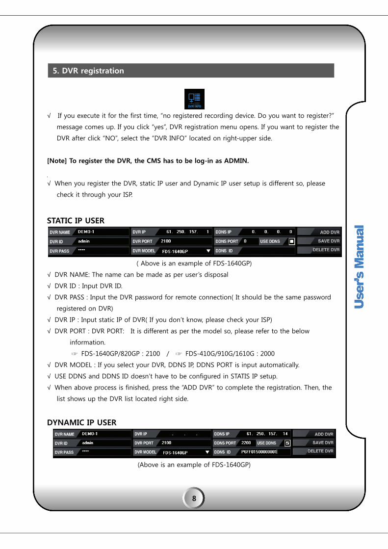
√ If you execute it for the first time, “no registered recording device. Do you want to register?”
message comes up. If you click “yes”, DVR registration menu opens. If you want to register the
DVR after click “NO”, select the “DVR INFO” located on right-upper side.
[Note] To register the DVR, the CMS has to be log-in as ADMIN.
√ When you register the DVR, static IP user and Dynamic IP user setup is different so, please
check it through your ISP.
STATIC IP USER
( Above is an example of FDS-1640GP)
√ DVR NAME: The name can be made as per user’s disposal
√ DVR ID : Input DVR ID.
√ DVR PASS : Input the DVR password for remote connection( It should be the same password
registered on DVR)
√ DVR IP : Input static IP of DVR( If you don’t know, please check your ISP)
√ DVR PORT : DVR PORT: It is different as per the model so, please refer to the below
information.
☞ FDS-1640GP/820GP : 2100 / ☞ FDS-410G/910G/1610G : 2000
√ DVR MODEL : If you select your DVR, DDNS IP, DDNS PORT is input automatically.
√ USE DDNS and DDNS ID doesn’t have to be configured in STATIS IP setup.
√ When above process is finished, press the “ADD DVR” to complete the registration. Then, the
list shows up the DVR list located right side.
DYNAMIC IP USER
(Above is an example of FDS-1640GP)
5. DVR registration
9
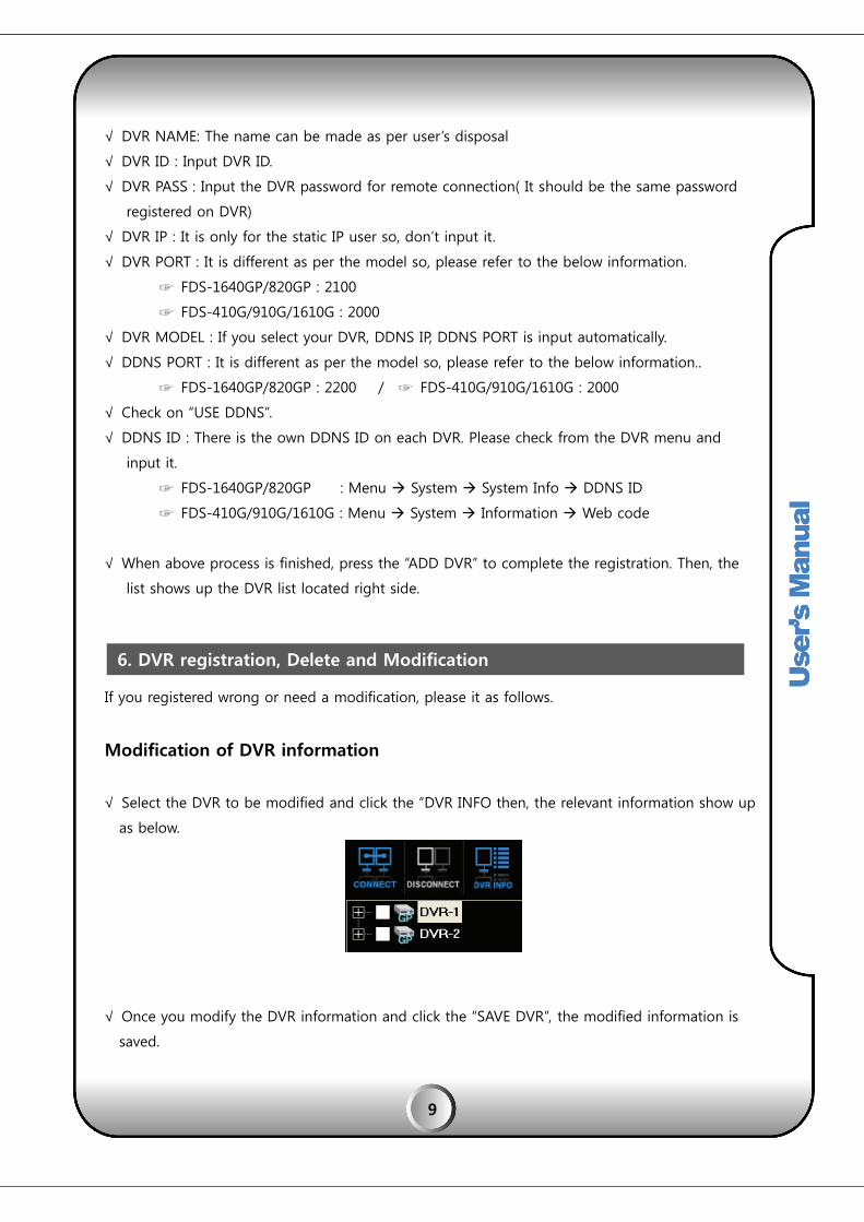
√ DVR NAME: The name can be made as per user’s disposal
√ DVR ID : Input DVR ID.
√ DVR PASS : Input the DVR password for remote connection( It should be the same password
registered on DVR)
√ DVR IP : It is only for the static IP user so, don’t input it.
√ DVR PORT : It is different as per the model so, please refer to the below information.
☞ FDS-1640GP/820GP : 2100
☞ FDS-410G/910G/1610G : 2000
√ DVR MODEL : If you select your DVR, DDNS IP, DDNS PORT is input automatically.
√ DDNS PORT : It is different as per the model so, please refer to the below information..
☞ FDS-1640GP/820GP : 2200 / ☞ FDS-410G/910G/1610G : 2000
√ Check on “USE DDNS”.
√ DDNS ID : There is the own DDNS ID on each DVR. Please check from the DVR menu and
input it.
☞ FDS-1640GP/820GP : Menu System System Info DDNS ID
☞ FDS-410G/910G/1610G : Menu System Information Web code
√ When above process is finished, press the “ADD DVR” to complete the registration. Then, the
list shows up the DVR list located right side.
If you registered wrong or need a modification, please it as follows.
Modification of DVR information
√ Select the DVR to be modified and click the “DVR INFO then, the relevant information show up
as below.
√ Once you modify the DVR information and click the “SAVE DVR”, the modified information is
saved.
6. DVR registration, Delete and Modification
10
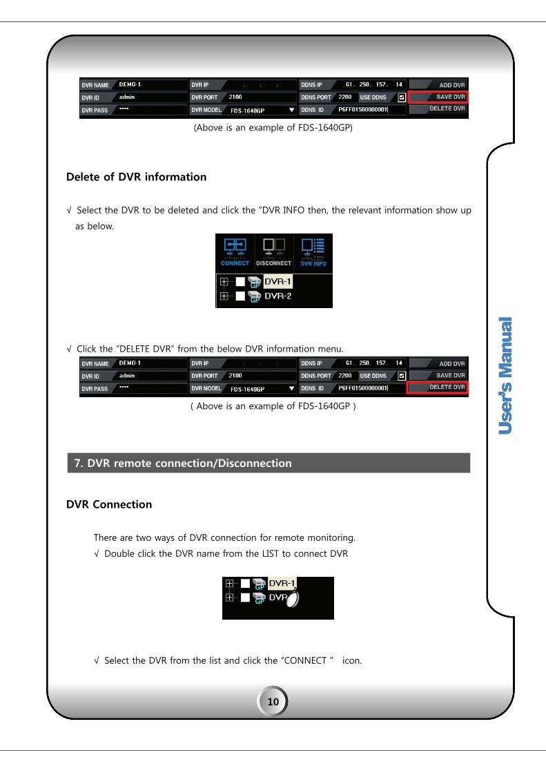
(Above is an example of FDS-1640GP)
Delete of DVR information
√ Select the DVR to be deleted and click the “DVR INFO then, the relevant information show up
as below.
√ Click the “DELETE DVR” from the below DVR information menu.
( Above is an example of FDS-1640GP )
DVR Connection
There are two ways of DVR connection for remote monitoring.
√ Double click the DVR name from the LIST to connect DVR
√ Select the DVR from the list and click the “CONNECT ” icon.
7. DVR remote connection/Disconnection

11
DVR disconnection
√ If you want to disconnect, select the DVR list and click the “DISCONNECT”.
DVR registration list shows the registered DVR, connection status, camera connection information
etc.,
[1] DVR Information display
√ The “GP”, “G” or “MP” is the name of the DVR.
√ Alarm display : If the red alarm icon is blinking on the DVR list, it means the event
happened on the relevant DVR.
[2] ㆍIf you click the “+” from the DVR list, you can see the camera information belongs to the
relevant DVR. Only blank-checked channel can see the image.(Default is checked all)
8. Registered DVR list function

12
CHANNEL COVERT
√ If you click the camera icon, it turns to “X” and the camera image doesn’t show up on CMS.
( It applies when it was re-connected)
√ It is nothing to do with the DVR unit but, it is concealing the image from the CMS itself.
13
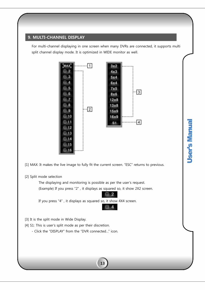
For multi-channel displaying in one screen when many DVRs are connected, it supports multi
split channel display mode. It is optimized in WIDE monitor as well.
[1] MAX: It makes the live image to fully fit the current screen. “ESC” returns to previous.
[2] Split mode selection
The displaying and monitoring is possible as per the user’s request.
(Example) If you press “2” , it displays as squared so, it show 2X2 screen.
If you press “4” , it displays as squared so, it show 4X4 screen.
[3] It is the split mode in Wide Display.
[4] S1: This is user’s split mode as per their discretion.
- Click the “DISPLAY” from the “DVR connected…” icon.
9. MULTI-CHANNEL DISPLAY

14
√ Select the split mode you want from the left-below menu.
SM ( Horizontal ) : Horizontal displaying channel selection.
SM ( Vertical ) : Vertical displaying channel selection.
Still Image [‘I’ Frame] : If the network is overloaded for many DVR connection at same time, you
can check the blank then, the image transmission mode is changing from the movie to still image
so, it reduce the network overload,(It transmit only ‘I” frame)
CLONE function floating the new CMS program so, you can floating 3,4,5,6.. CMS screen. If you
have multi-monitor, you can move the cloned CCMS to the monitor 2, 3, 4, …
Since this CLONE screen is saved, if you click the CLONE in next connection, the same saved
CLONE is floating again.
11. CLONE(grouping function)
10. I FRAME STREAMING

15
( Click the “CLON” from the upper function list)
[Feature and usage]
√ Each different DVRs can be shown as a single connection and this function could be used as a
‘VIRTUAL DVR’. For example, if you click the specific camera from DVR1 and specific camera
from DVR 2 and specific camera from DVR 3… After disconnect all the DVR and connect all DVR
again then, all selected specific channel shows. Click the CLONE then, CLONE 1 is the VIRTUAL
DVR No. 1. (Grouping)
√ Each DVR control is useful.
√ Multi E-map floating is possible.
[1] If you click the “CLON”, the connection way looks same as the new CMS connection.
[2] The connection can be made by the ADMIN password. Then, you will see the CLONE1. This
means the first clone so, if you click the ‘CLONE’ again, CLONE2 is floating. If you disconnect and
connect again, and click the ‘CLONE’, the saved ‘CLONE’ will be floated again.

Once yo
automat
√ ‘CH
It makes
Click the
√ ‘CH
☞
☞
12. A
13. S
ou check the
tically.( But,
ECK’ the bla
s the selecte
e “SEQ CON
HECK’ the DV
Seq Con Nu
Seq Con Int
AUTO CON
SEQ CON
e listed DVR
once the CM
ank to select
ed DVR sequ
” for workin
VR to be seq
um : Select h
: Select the
N
and click th
MS is termin
t the DVR to
uence during
g. If it works
quenced.
how many D
duration of
16
he AUTO CO
ated, AUTO
o be connect
g the selecte
s, the color
VR to show
f sequence.
N, all checke
CON functio
ted as ‘AUTO
ed time.
of button tu
in one scree
ed DVR is co
on is release
O CON’.
urns blue.
en.
onnected
ed )

17
[Notice]
SEQ CON works at least 2 DVRs are selected.
√ If you checked 3 DVRs, and selected “Seq Con Num =1” , “Seq Con Int=10”, it shows
DEMO-1 DVR for 10seconds and sequencing to DEMO-2 and DEMO-3.
√ If you checked 3 DVRs, and selected “Seq Con Num =2” , “Seq Con Int=10”, it shows
DEMO-1 and DEMO-2 in one screen for 10seconds and, sequencing to DEMO-3 and
DEMO-1.. DEMO-2 and DEMO-3..
√ If you click the “SEQ CON”, the sequencing starts and icon turns blue. If you click again, it
is released.
SINGLE MODE is needed when there is no multi-DVR connection. If you connect it based on
SINGLE MODE, the connection is automatically made as per the original DVR
split.(16Ch/9Ch/8Ch/4Ch).
14. SINGLE MODE
18
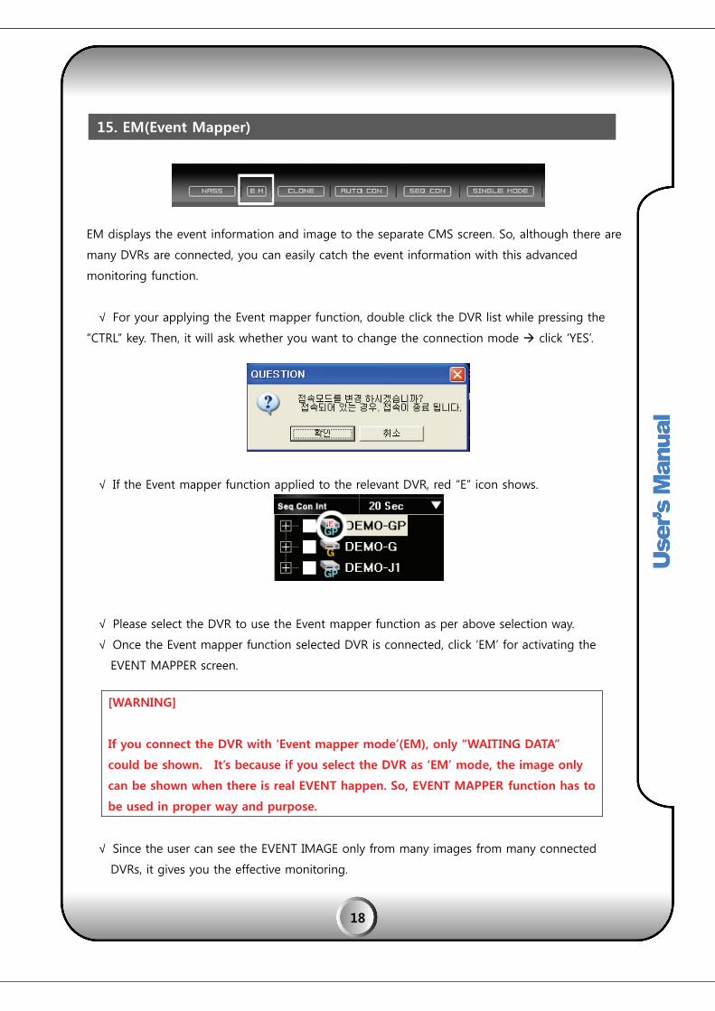
EM displays the event information and image to the separate CMS screen. So, although there are
many DVRs are connected, you can easily catch the event information with this advanced
monitoring function.
√ For your applying the Event mapper function, double click the DVR list while pressing the
“CTRL” key. Then, it will ask whether you want to change the connection mode click ‘YES’.
√ If the Event mapper function applied to the relevant DVR, red “E” icon shows.
√ Please select the DVR to use the Event mapper function as per above selection way.
√ Once the Event mapper function selected DVR is connected, click ‘EM’ for activating the
EVENT MAPPER screen.
[WARNING]
If you connect the DVR with ‘Event mapper mode’(EM), only “WAITING DATA”
could be shown. It’s because if you select the DVR as ‘EM’ mode, the image only
can be shown when there is real EVENT happen. So, EVENT MAPPER function has to
be used in proper way and purpose.
√ Since the user can see the EVENT IMAGE only from many images from many connected
DVRs, it gives you the effective monitoring.
15. EM(Event Mapper)

19
[Event Mapper description]
√ Auto Scroll : If the new event happen, the list updates automatically.
If you want to search the certain image or event list, you’d better to uncheck the “Auto Scroll”.
√ Update Item : The event list or image is not updated on the screen.
√ Write Log : It saves the event list as log file.
√ Write Image : It saves the event image automatically on the PC.
Since it occupies the HDD space on your PC, you have to be very careful when you use.
√ CONNECT LIVE : Once you select the ‘LIST’ and click the “CONNECT LIVE”, it shows the
relevant DVR screen.
√ VIEW CHANNEL : Once you select the ‘LIST’ and click the “VIEW CHANNEL”, one channel is
floating as a VIEW channel.
√ DIRECT SEARCH : Once you select the ‘LIST’ and click the “DIRECT SEARCH”, it searches the
relevant event.
[Notice]
If you uncheck the ‘Update Item’ you can not use “write log” and “write Image”.

20
NASS supports the remote schedule backup. The schedule backup makes possible to backup on
designated time by the multi user.
[1] Click the “NASS” button for schedule backup.
[2] Register the DVR to make the schedule backup.
(STATIC IP USER)
√ DVR NAME: The name can be made as per user’s disposal
√ ID : Input DVR ID.
√ PASS : Input the DVR password for remote connection( It should be the same one registered on
DVR)
√ ADDRESS: Input static IP of DVR( If you don’t know, please check your ISP)
√ PORT : DVR PORT: It is different as per the model so, please refer to the below information.
☞ FDS-1640GP/820GP : 2100 / FDS-410G/910G/1610G : 2000
√ DEVICE: Select the DVR model to connect.
√ DDNS IP, DDNS PORT and DDNS ID don’t have to be configured in STATIC IP setup.
√ When above process is finished, press the “ADD DVR” to complete the registration. Then, the
list shows up the DVR list located right side.
(DYNAMIC IP USER)
√ DVR NAME: The name can be made as per user’s disposal
√ ID : Input DVR ID.
√ PASS : Input the DVR password for remote connection( It should be the same password
16. NASS( SCHEDULE BACKUP)
21
registered on DVR)
√ ADDRESS : It is only for the static IP user so, don’t input it.
√ PORT : It is different as per the model so, please refer to the below information.
☞ FDS-1640GP/820GP : 2100
☞ FDS-410G/910G/1610G : 2000
√ DEVICE : Select the DVR model to connect.
√ Input the DDNS IP as “61.250.157.14”
√ DDNS PORT : It is different as per the model so, please refer to the below information..
☞ FDS-1640GP/820GP : 2200 / FDS-410G/910G/1610G : 1900
√ Check on “USE DDNS”.
√ DDNS ID : There is the own DDNS ID on each DVR. Please check from the DVR menu and
input it.
☞ FDS-1640GP/820GP : Menu System System Info DDNS ID
☞ FDS-410G/910G/1610G : Menu System Information Web code
√ When above process is finished, press the “ADD DVR” to complete the registration. Then, the
list shows up the DVR list located right side.
[Notice]
NASS function is available on G and FP series DVRs. The DVR registration is same as it on CMS.
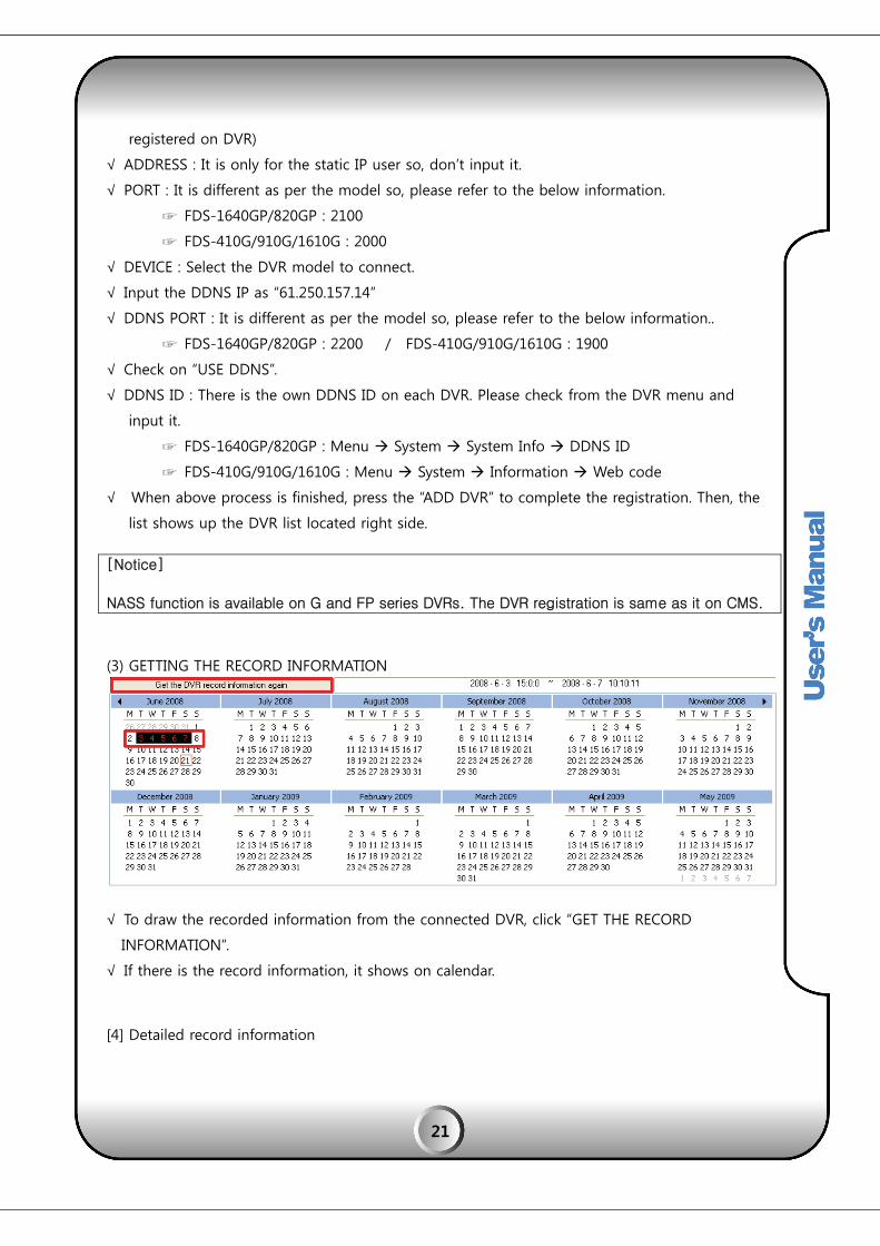
(3) GETTING THE RECORD INFORMATION
√ To draw the recorded information from the connected DVR, click “GET THE RECORD
INFORMATION”.
√ If there is the record information, it shows on calendar.
[4] Detailed record information
22
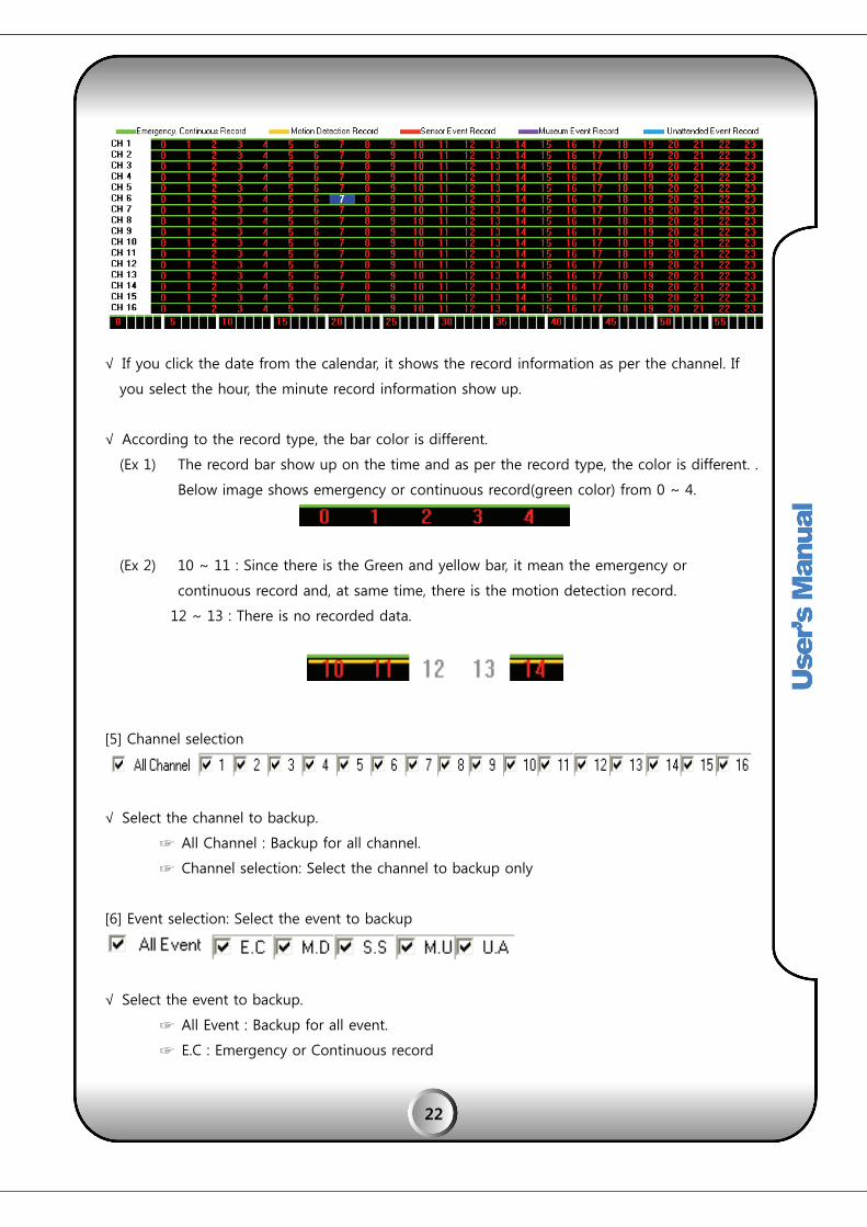
√ If you click the date from the calendar, it shows the record information as per the channel. If
you select the hour, the minute record information show up.
√ According to the record type, the bar color is different.
(Ex 1) The record bar show up on the time and as per the record type, the color is different. .
Below image shows emergency or continuous record(green color) from 0 ~ 4.
(Ex 2) 10 ~ 11 : Since there is the Green and yellow bar, it mean the emergency or
continuous record and, at same time, there is the motion detection record.
12 ~ 13 : There is no recorded data.
[5] Channel selection
√ Select the channel to backup.
☞ All Channel : Backup for all channel.
☞ Channel selection: Select the channel to backup only
[6] Event selection: Select the event to backup
√ Select the event to backup.
☞ All Event : Backup for all event.
☞ E.C : Emergency or Continuous record

23
☞ M.D : Motion detection record
☞ S.S : Sensor record
☞ M.U : Museum record(Missiong object)
☞ U.A : Unattended
[8] Backup duration setup
√ Select the backup start/end time from the recorded data on DVR.
[9] Select the saving folder
Select the folder to save the backup file by “Find folder” icon click.
[10]) Backup execution time setup
√ This is the backup executing time.
☞ All time : Backup all time
☞ Time selection: If you select the time, the actual backup is executing on selected time.
[11] Backup day selection.
√ Select the day to execute the backup.
☞ All day : The backup is made all day.
☞ Day selection : The backup is executing on selected day.
[Notice]
[Note] Although the backup is not completed during the backup execution
time, it will be stopped. If you selected the next backup execution day, the
stopped backup data will be continued.

24
[12] Backup start
For backup start, click the “Start schedule backup”.
[13] Baup stop
For backup stop, click the “Stop schedule backup”.
[14] Open backup folder

CMS pro
Chann
It enlarg
ㆍOne c
chann
ㆍOn th
chann
ㆍOne c
want to
17. S
ovides variou
el Viewer
ges the spec
channel pop
nel which wa
he pop-up w
nel of DVR. .
channel full
o see full mo
SCREEN CO
us display co
ific channel
-up : Press “
ant to enlarg
window, doub
mode : Dou
ode. ( If us
ONTROL
ontrol for m
while monit
“Ctrl” key an
ge.
ble click the
ble click the
ser want to r
25
onitoring an
toring
d double cli
left button
e left button
return split m
nd user’s con
ick the left b
of mouse, S
of mouse o
mode, doubl
nvenience.
button of mo
-PIP screen
on the specif
e click again
ouse on the
which is ent
fic channel w
n. )
specific
tire
which

S-PIP
Double
up as a
DIGITA
This fun
mosaic
click the cer
PIP.
AL ZOOM
nction is prov
could be see
rtain channe
viding softw
en as screen
el while pres
ware digital z
n is zoomed
26
sing the “Sh
zoom In/Out
in.
hift”, the cha
of target po
nnel involve
oint on the
ZOOM I
ZOOM O
ed DVR imag
screen. Pixel
N
OUT
ge shows
ls or

[How to
Select
wheel
return
[No
* D
* D
The colo
√ It sh
number
√ Dist
☞
☞ Y
☞
This me
changed
[1] TIME
[2] MOT
MD :
18. C
19. D
o use]
t single full
l of the mo
n normal scre
tice]
Digital zoom
Digital zoom
or change a
hows the str
of DVR cha
tinguishing a
Red : 0~1 f
Yellow : 2 fr
Green : Ove
nu is to sele
d in blue col
E / CHANNE
TION/SENSO
: Motion De
CH Net Sta
Display Se
channel and
ouse, screen
een.
function is
function is
as per the st
reaming sta
annel.
as per the c
frame stream
rames
er 3 frames
ect various d
lor)
L MODE: Tim
OR/V LOSS /
tection
atus
tup
d place mou
can be zo
not available
not available
reaming fra
tus in Live m
olor.
ming.
display optio
me and Chan
REC: Motion
27
se cursor w
omed in an
e on multi c
e on S-PIP s
me.
mode. The c
ons and reso
nnel informa
n, Sensor, Vi
here user w
nd out. Dou
channels scre
screen.
channel info
lution info o
ation display
deo loss and
wants to zoo
uble click le
een.
rmation sho
on screen. (S
y on screen..
d Recording
m in. By usi
ft mouse b
ows as per th
Selected butt
status displ
ng scroll
utton to
he
ton
ay.

SS :
VL :
MU :
NU :
[3] FPS /
[4] SHO
[5] HIDE
This fun
√ Sav
₩
Backup
PC.
√ Clic
√ Sele
sele
21. B
20. C
Sensor Dete
Video Loss
: Museum D
Unattanded
/ RESOLUTIO
W ALL: Disp
E ALL: Conce
nction is to c
ving folder: C
function ca
ck the backu
ect directory
ected)
BACKUP
CAPTURE
ection
Detection
d Detection
ON: Frame, R
play all above
ealing all dis
capture curre
C:\MY DOC
an save the a
p button.
y to save ach
Resolution in
e (1)~(3) inf
play informa
ent screen im
CUMENTS\C
archiving file
hieved backu
28
nfo display.
ormation.
ation.
mage and sa
CMS\CAPTU
e from live im
up data. (It s
ave into PC.
URE.
mage or pla
saves in defa
ayback imag
ault directory
ge into the re
y if no direc
emote
tor is

√ Inpu
√ Sele
√ Clic
Backup
√ Bac
Remote
informat
FDS-41
[Hard D
[1] To
[2] U
[3] Ty
√
√
22. R
ut file name
ect channel.
ck “OK” to co
button to st
ckup starts w
setup provi
tion.
10G/910G/
Disk]
otal Hard Di
sable HDD c
ype of savin
Overwrite : H
Stop Record
REMOTE S
. (If file nam
onfirm the s
top the proc
when you clic
des remote
1610G Mo
sk capacity
capacity
g selection
HDD will ove
ding : Record
ETUP
me is not assi
etup. (As ba
cess.)
ck “Backup”
user to call
del
erwrite from
ding stops w
29
igned, it will
ckup starts,
button and
DVR main m
m the first wh
when HDD is
create sugg
menu windo
end as “Bac
menu for rem
hen HDD is f
s full
gesting file n
ow will be d
ckup” button
mote user to
full.
name autom
disappeared.
n is clicked a
o change set
matically)
Click
again
tup
30
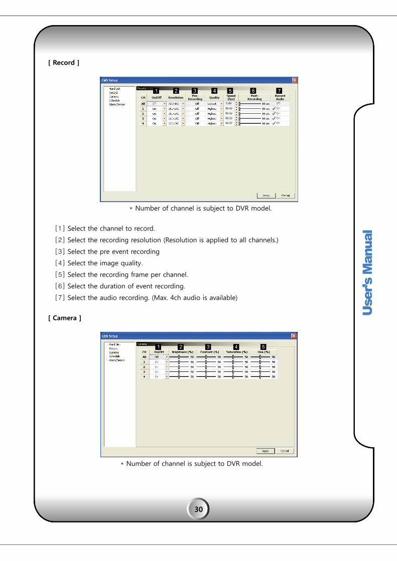
[ Record ]
* Number of channel is subject to DVR model.
[1] Select the channel to record.
[2] Select the recording resolution (Resolution is applied to all channels.)
[3] Select the pre event recording
[4] Select the image quality.
[5] Select the recording frame per channel.
[6] Select the duration of event recording.
[7] Select the audio recording. (Max. 4ch audio is available)
[ Camera ]
* Number of channel is subject to DVR model.

31
[1] Select a camera ON / OFF
[2] Adjust the brightness level.
[3] Adjust the contrast level.
[4] Adjust the saturation level.
[5] Adjust the hue level.
[ Schedule ]
Remote setup for recording schedule.
[1] Select the channel.
[2] Click or drag the time table to assign recording schedule.
[3] Select the type of event. ( Each different color indicates the event type).
[4] All CH to copy : Copy the schedule to all channel.
[5] Channel to copy : Copy the schedule to the next channel
[6] Delete the schedule setup for channel.

32
[ Alarm / Sensor ]
Remote setup for Alarm / Sensor.
* Number of channel is subject to DVR model.
[1] Sensor
√ All : Apply to all channel.
√ On/Off : Select whether to use sensor
√ Input type : Select sensor contact type. (Normal / Normal Close)
[2] Alarm
√ All : Apply to all channel.
√ Detection : Select the type of event alarm out.
√ Alarm out time : Select the alarm out duration.
√ Internal buzzer : Select the internal buzzer duration.

33
FDS-820GP/1640GP Model
[ System ]
[1] Firmware version of DVR.
[2] Video format information.
[3] Capacity of hard disk drive.
[4] Information of used HDD.
[5] Disk full option
√ Overwrite : HDD will overwrite from the first when HDD is full
√ Stop Recording : Recording stops when HDD is full
[Record]
* Number of channel is subject to DVR model.

34
[1] Resolution : Select the recording resolution per channel.
[2] Quality : Select the image quality per channel
[3] FPS : Select the recording frame for normal recording.
[4] Ramp-up : Select the recording frame for event recording.
[Ramp-up]
* Number of channel is subject to DVR model..
[1] Pre Rec : Select whether use pre recoding when event.
[2] Event : Select the type of event.
[3] Quality : Select the image quality.
[4] Display the frame rate which configured on record setup menu.

35
[Camera]
* Number of channel is subject to DVR model.
[1] Adjust the brightness level.
[2] Adjust the contrast level.
[3] Adjust the saturation level.
[Schedule]
Remote setup for recording schedule.
√ Auto delete : Select whether auto delete use

36
[Weekly]
[1] Select the channel
[2] Drag to assign the schedule on time table.
√ 1st line : Continuous recording (Green)
√ 2nd line : Motion detection recording (Yellow)
√ 3rd line : Sensor detection recording (Red)
√ 4th line : Museum detection recording (Violet)
√ 5th line : Unattended detection recording (Blue)
[3] Apply the schedule setup to all date.
[4] Apply the schedule setup to all channel.
[5] Delete all recording schedule.
[6] To delete specific schedule, check the “DELETE mode” same as press “Shift” button and
drag to delete specific schedule.

37
[Holyday]
[1] Select the channel
[2] Drag to assign the schedule on time table.
√ 1st line : Continuous recording (Green)
√ 2nd line : Motion detection recording (Yellow)
√ 3rd line : Sensor detection recording (Red)
√ 4th line : Museum detection recording (Violet)
√ 5th line : Unattended detection recording (Blue)
[3] Apply the schedule setup to all channel.
[4] Delete all recording schedule.
[5] To delete specific schedule, check the “DELETE mode” same as press “Shift” button and
drag to delete specific schedule.
[6] To register the holyday, click the date.

38
[Alarm]
Remote setup for Alarm
* Number of channel is subject to DVR model
[1] Select the preset No. of relevant PTZ camera
[2] Select the Alarm output No. It supports 8 and can be extended upto 128.
[3] Select whether use key sensor function. ( Please refer to the DVR manual )

39
[Sensor]
Remote setup for sensor.
* Number of channel is subject to DVR model
[1] Select the type of sensor input.
√ N/O : Normal Open
√ N/C : Normal Close
[2] Select the sensor per channel. Selected sensor change in orange color.
(Above sample shows the sensor 1,2,3,4 are linked with channel 1)

This me
[1] To
[2] So
[3] Ev
The TIM
[1]
[2]
[3]
[4]
[5]
23. S
24. S
nu is to hea
o hear sound
ound OFF al
vent sounds
ME, EVENT,
Search by t
Search by e
Search by e
Playback co
“LIVE” butto
SOUND
SEARCH
ar audio sou
d from selec
ll the channe
on checked
CALENDAR
time.
event
event.
ontroller.
on: It turns t
nd in remot
cted channel
els
d event
search is p
to live scree
40
e.
l
ossible as p
n from Playb
per the differ
back.
rent DVR moodels.
41
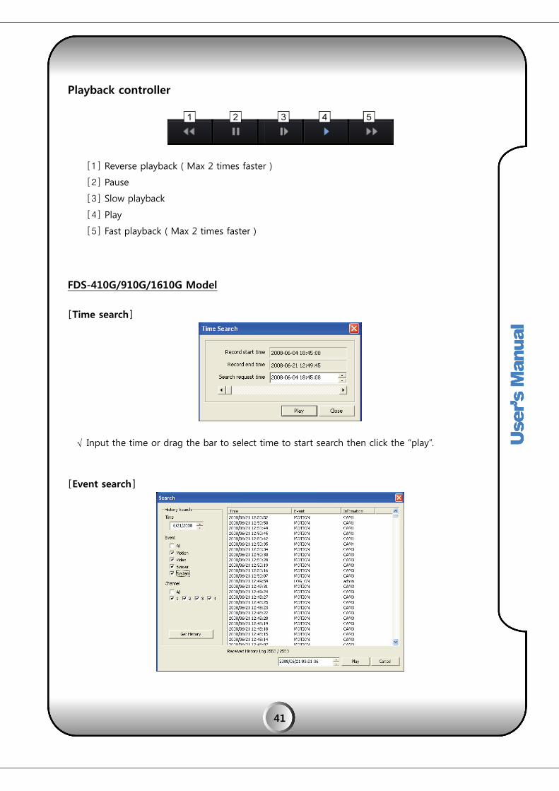
Playback controller
[1] Reverse playback ( Max 2 times faster )
[2] Pause
[3] Slow playback
[4] Play
[5] Fast playback ( Max 2 times faster )
FDS-410G/910G/1610G Model
[Time search]
√ Input the time or drag the bar to select time to start search then click the “play”.
[Event search]

42
[1] Select the date.
[2] Select the event type
√ All : Search to all event
√ Motion : Search to motion detection
√ Video : Search to video loss
√ Sensor : Search to sensor detection
√ System : Search to system log
[3] Channel : Select the channel to search for all or specific channel.
[4] Get History : To show the list of events
[5] Choose the list then click “Play” button to play.
[Calendar search]
* Number of channel is subject to DVR model.
[1] Day Selection: Select Date on the Calendar
* Green colored date on the calendar indicates recorded data exist on the date..
[2] Hour Select: Select hour on the bar screen
[3] Minute Select: Select minutes and press “Play” to start playback.

43
FDS-820GP/1640GP Model
[Time search]
√ Input the time or drag the bar to select time to start search then click the “play”
[Event search]
[1] History search : Select the event type and click “Get history”
[2] Choose the list then click “Play” button to play.

44
[Calendar search]
* Number of channel is subject to DVR model.
[1] Day Selection: Select Date on the Calendar
* Green colored date on the calendar indicates recorded data exist on the date..
[2] Hour Select: Select hour on the bar screen
[3] Minute Select: Select minutes and press “Play” to start playback
On the CMS program, user can remotely operate PTZ cameras and the function includes ZOOM,
FOCUS, PRESET, TOURING functions.
25. PTZ CONTROL

45
[1] PTZ camera speed selection.
√ SPEED X1 , SPEED X2., SPEED X4
PTZ speed can be selected while PTZ moving, Zooming or Focusing
[2] PTZ camera direction control
PTZ camera moving direction can be easily controlled by mouse click.
UP
Left Right
Down
[3] AUTO FOCUS of PTZ camera
√ ZOOM : Zoom In/Out of PTZ camera.
√ AUTO FOCUS ; Automatic camera focusing.
√ FOCUS : It focusing the camera.
ZOOM IN/FOCUS IN
축소/감소
ZOOM OUT/FOCUS OUT
[4] PRESET
PRESET function is to call initially saved camera positions of PTZ camera. Max. 16 preset
positions can be saved on CMS.

√ P
√ P
This fun
START”
[1] AUT
It is
eac
√
√
√ I
√
[2] TOUIt is
√
26. P
RESET SAVE
RESET MOV
nction is for
and “TOURI
TO START
s intensive m
h preset pos
START PRES
END PRESET
INTERVAL: S
AUTO STAR
URING STARs intensive m
Save select
☞ SKIP :
☞ 1~16
PTZ TOURI
E : Fix PTZ ca
on preset
VE : Select N
PTZ cam
r intensive (
NG START” a
monitoring a
sition can be
ET: Select fir
T: Select seco
Select dwell t
RT: It starts
positions
RT
monitoring by
ted position
: This No. wi
: Save PTZ c
ING (POIN
amera positi
position No
No. from the
mera.
(repeat) mo
are available
against two
e selected.
rst preset po
ond preset p
time at each
s automatic
s as per con
y repeat tou
to PRESET N
ill be skippe
camera posi
NT TO PO
46
ion and sele
o.1. The rest
e PRESET M
nitoring two
e.
PTZ preset p
osition.
position.
h position.
c monitoring
figured.
uring of selec
No. on the li
d from TOU
itions to eac
INT)
ect No. 1 on
15 position
OVE tool to
o or more
positions rep
g between
cted positio
ist.
RING.
ch PRESET N
n PRESET SAV
can be save
o call relevan
preset posit
peatedly in o
the PTZ c
n of PTZ.
o. on the lis
VE tool, and
ed as the sa
nt preset po
tions of PTZ
order. Dwell
amera’s two
st.
d it saves
me.
ositioned
Z. “AUTO
time on
o preset
√
√
This is a
of event
[1] It
m
[2] Ev
C
[ To
27. E
INTRVAL
TOURING S
an electronic
ts by camera
t provides se
map (Double
vent icon TO
Collection of
NOTE ]
o use TOURI
E-MAP
: Select dwe
START : It st
c map displa
as, sensors a
electable ma
click of full
OOL
“Camera”, “S
ING function
ell time at ea
arts touring
ay to provid
and DVRs on
aximum 16
E-map retu
Sensor”, “DV
n, at least 3
47
ach position
to all the p
de efficient m
n the map.
E-maps on
rns to multi
VR” icons use
preset posit
.
reset positio
monitoring v
screen, and
map)
ed for E-ma
tions or mor
oned list as p
viewing the
d double clic
p configurat
re are require
per the dwe
positions an
ck will maxi
tion
ed .
ll time.
nd status
mize the

48
[3] E-map list
It is for importing the new E-MAP image file from the PC or, external device.
[4] POP UP : The image window will be shown on the e-map when alarm triggered.
[How to register E-map]
To use this function, BMP file E-map image must be registered on the E-map screen.
Browse E-map image file by selecting “IMPORT MAP”, and input new E-map name on the list. By
the same procedure, additional map can be registered. (Double click of e-map title can modify the
title description / DELETE key is for selected E-map removal from the list)
[E-map image positioning]
By using mouse, select an E-map title and drag onto the position where you want place among
16 split map screen, then connected icon image is registered automatically. (Drag and Drop)

49
√ positioning the icons (DVR, Camera, Sensor) to a E-map, make it full screen by double click.
√ Put the icons by dragging the mouse onto the E-map.
√ For detailed configuration, option window will be opened from the positioned icon.
(Icon selection)
√ Select DVR : Select DVR where the camera is connected.
√ Select channel : Select channel where the camera is connected.
(DVR selection)
Aside from Camera or Senor icon display on E-map, separate DVR icon can be positioned
on the E-map. The DVR icon will be blinking any event which is happening on the same
DVR.

50
[Icon deletion on E-map]
Select the icon and press “DELETE” key on PC keyboard.
[E-map Pop-up viewer]
The icon on E-map will be blinking when an event happens then, user can view its image by
double clicking the icon. It shows the relevant channel image.
√ To be enable auto popup, check in the PopUp box.
√ When click the camera icon, image will be shown.

51
MEMO