feasibility assessment of an innovative isolation bearing system with shape memory alloys
TRANSCRIPT

Journal of Earthquake Engineering, 13(S1):18–39, 2009
Copyright Ó A.S. Elnashai & N.N. Ambraseys
ISSN: 1363-2469 print / 1559-808X online
DOI: 10.1080/13632460902813216
Feasibility Assessment of an Innovative Isolation
Bearing System with Shape Memory Alloys
GABRIELE ATTANASI1, FERDINANDO AURICCHIO2,
and GREGORY L. FENVES3
1ROSE School, IUSS Pavia, Pavia, Italy2Dipartimento di Meccanica Strutturale, Universita degli Studi di Pavia, Pavia,
Italy3Department of Civil and Environmental Engineering, University of California,
Berkeley, California, USA
The objective of this work is to investigate the feasibility of a new seismic isolation device conceptbased on the superelastic effect given by shape memory alloys. Seismic isolation is one of the mosteffective options for passive protection of structure, which modifies the global response andimproves performances, in particular regularizing the structural response, shifting the fundamentalperiod of vibration, and increasing the global energy dissipation. Shape memory alloys (SMAs) arecharacterized by unique mechanical properties due to a solid-solid transformation between phasesof the alloy. They show high strength and strain capacity, high resistance to corrosion and tofatigue. Regarding the stress-strain constitutive law, the nonlinear hysteresis due to the superelasticeffect, that for particular range of temperature can be described like a flag shaped relation, avoidsresidual deformation, provides some hysteretic energy dissipation and limits the maximum trans-mitted force. An isolation bearing system based on a SMA superelastic effect is intended to providethe nonlinear characteristics of yielding devices, limiting the induced seismic force and providingadditional damping characteristics, together with recentering properties to reduce or eliminate thecumulative damage. Flag-shape hysteresis is characterized by much less energy dissipation withrespect to other isolation device technology force-displacement relations, therefore its effectivenesshas to be investigated. In this work the dynamic response of the proposed innovative SMA isolationdevices has been compared with equivalent traditional bearing response through dynamic timehistory analyses. Results show that force and displacement demands in the two systems are quitesimilar for medium to high flag-shape dissipation capability range.
Keywords Seismic Isolation; Shape Memory Alloys; Superelastic Effect
1. Introduction
Major developments have occurred in the last years on advanced material properties. The
term advanced in the civil structural context refers to a capability to increase the
structural performance and safety and the building designs lifetime and its serviceability
with respect to traditional materials. A key aspect to move towards the improved
structural technology is the development of advanced materials and its integration in
innovative structural systems to provide improved performance. An example of smart
materials is Shape Memory Alloys, which have unique properties, including Young’s
modulus-temperature relations, shape memory effects, superelastic effects, and high
Address correspondence to Gabriele Attanasi, European School for Advanced Studies in Reduction of
Seismic Risk (ROSE School), IUSS Pavia, via Ferrata 1, 27100 Pavia, Italy; E-mail: [email protected]
18
Downloaded By: [Biblioteca Fac di Ingegneria] At: 09:46 14 April 2009

damping characteristics [Song et al., 2006]. These properties, which have led to numer-
ous applications in the biomedical and aerospace industries, have been also evaluated for
applications in the area of seismic resistant design and retrofitting [DesRoches and Smith,
2003].
In this work, we focus on the possibility of integrating the SMA application in
seismic isolation technology, investigating the potential advantages.
1.1. Seismic Isolation
Seismic isolation mitigates the earthquake effects on buildings and their potentially
vulnerable contents by modifying the structural global response and improving the
performance. This can be obtained by:
� protecting part of the structure assuring its elastic response;
� shifting the main period of vibration to a convenient value that modifies both
acceleration and displacement demand;
� increasing the global energy dissipation capacity of the structure thus reducing its
displacement demand;
� regularizing the response, modifying the effective relative stiffness, and strength
of different parts of the structure.
However, design of isolated structures has some particular concerns. Practical isolation
systems must balance between the extent of force isolation and acceptable relative
displacements across the isolation system during earthquakes. An extensive and exhaus-
tive description of the topic can be found in Skinner et al. [1993], Naeim and Kelly
[1999], Christopoulos and Filiatrault [2006], and Priestley et al. [2007].
1.2. Shape Memory Alloys
Shape memory alloys are a novel functional material with increasing applications in
many areas, recently also in response control of civil structures [Song et al., 2006]. SMAs
have energy dissipation capabilities, large elastic strain capacity, hysteretic damping,
good high- and low-cycle fatigue resistance, recentering capabilities, and excellent
corrosion resistance [DesRoches and Smith, 2003].
1.2.1. Shape Memory and Superelastic Effects. The most important properties showed
by the SMA are the shape memory and the superelastic effects. These unique properties
are the result of reversible phase transformations of SMAs. There are two crystal structure
phases in SMAs: the austenite, stable at high temperature, and the martensite, stable at
low temperature.
In its low-temperature phase, if loaded, SMAs exhibit the shape memory effect.
When SMAs in martensite are subjected to external stress, they deform through a so-
called detwining mechanism up to several percent strains. Unloading results in a residual
strain, as shown in Fig. 1. Heating the previously deformed specimen above a determined
temperature results in phase transformation, and a recovering of the original shape
(removal of the residual strain).
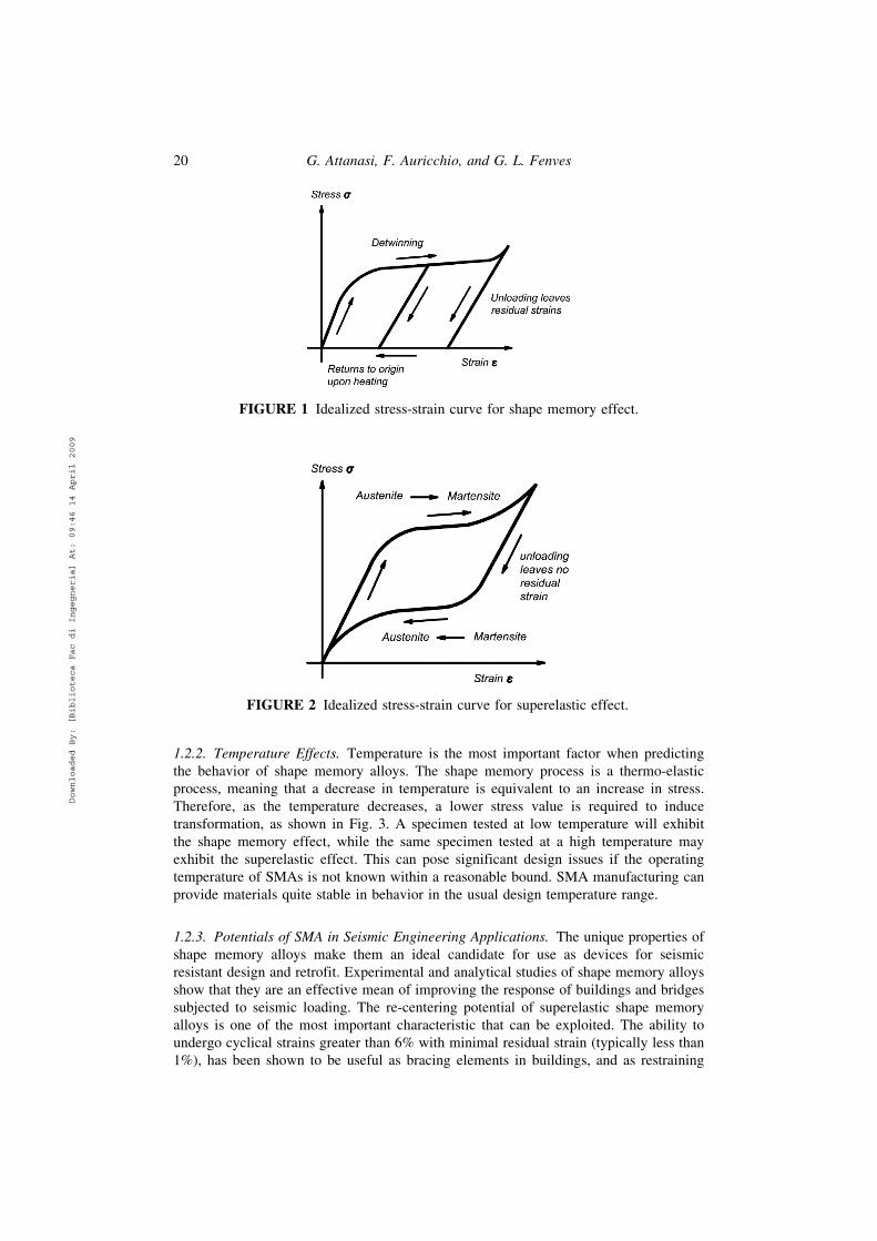
In its high-temperature form, SMAs exhibit a superelastic effect. Originally in
austenitic phase, martensite is formed upon loading beyond a certain stress level, result-
ing in the stress plateau shown in Fig. 2. However, upon unloading, the martensite
becomes unstable, resulting in a transformation back to austenite and the recovery of
the original, undeformed shape.
Feasibility Assessment of an Innovative Isolation Bearing System 19
Downloaded By: [Biblioteca Fac di Ingegneria] At: 09:46 14 April 2009
1.2.2. Temperature Effects. Temperature is the most important factor when predicting
the behavior of shape memory alloys. The shape memory process is a thermo-elastic
process, meaning that a decrease in temperature is equivalent to an increase in stress.
Therefore, as the temperature decreases, a lower stress value is required to induce
transformation, as shown in Fig. 3. A specimen tested at low temperature will exhibit
the shape memory effect, while the same specimen tested at a high temperature may
exhibit the superelastic effect. This can pose significant design issues if the operating
temperature of SMAs is not known within a reasonable bound. SMA manufacturing can
provide materials quite stable in behavior in the usual design temperature range.
1.2.3. Potentials of SMA in Seismic Engineering Applications. The unique properties of
shape memory alloys make them an ideal candidate for use as devices for seismic
resistant design and retrofit. Experimental and analytical studies of shape memory alloys
show that they are an effective mean of improving the response of buildings and bridges
subjected to seismic loading. The re-centering potential of superelastic shape memory
alloys is one of the most important characteristic that can be exploited. The ability to
undergo cyclical strains greater than 6% with minimal residual strain (typically less than
1%), has been shown to be useful as bracing elements in buildings, and as restraining
FIGURE 2 Idealized stress-strain curve for superelastic effect.
FIGURE 1 Idealized stress-strain curve for shape memory effect.
20 G. Attanasi, F. Auricchio, and G. L. Fenves
Downloaded By: [Biblioteca Fac di Ingegneria] At: 09:46 14 April 2009

elements in bridges. More extensive description of the SMA potentials in civil engineering
applications is given in Song et al. [2006] and DesRoches and Smith [2003].
2. Feasibility of SMA Technology for Seismic Isolation
We want to investigate the possibility of using shape memory alloys in seismic isolation
devices and to evaluate its effectiveness in reaching the structural design goals, compared
with traditional isolation devices. In this context, the term shape memory alloys device
refers to a bearing systems characterized by a non-linear horizontal force-displacement
relation which can be described by a flag-shape hysteresis [DesRoches et al., 2004].
We assume a bearing system providing a horizontal base shear as a function of
displacement like the one shown in Fig. 4. This force-displacement relation is given
by the superelastic effect of shape memory alloys eventually coupled with other sources
of stiffness. The key parameters characterizing the nonlinear behavior of the device
(Fig. 4) are:
FIGURE 4 Parameters for the SMA superelastic force-displacement model.
FIGURE 3 Idealized temperature dependent force-displacement response of superelastic
NiTi.
Feasibility Assessment of an Innovative Isolation Bearing System 21
Downloaded By: [Biblioteca Fac di Ingegneria] At: 09:46 14 April 2009

� K: initial lateral stiffness for the system, relative to the first shape memory alloy
stiffness contribution and, eventually, to the other stiffness sources;
� Vy: lateral force corresponding to the reaching of the device linear limit; it can be
interpreted as the shear that produces the initial transformation in the shape
memory alloys;
� uy: lateral displacement corresponding to reaching of the linear limit of the force-
displacement relation for the device;
� Vd: lateral force corresponding to reaching of the end of plateau limit; it can
be interpreted as the shear at the end of transformation in the shape memory
alloys;
� ud: lateral displacement corresponding to reaching of the end of plateau limit;
� r1K: lateral stiffness for the system after reaching the shape memory alloy elastic
limit loading, taking also in account, eventually, the other stiffness sources; r1 is
the fraction of the loading second stiffness respect the first one;
� aK: lateral stiffness for the system after reaching the shape memory alloy second
elastic limit at the end of the phase transformation; a is the fraction of the
unloading second stiffness respect the initial one;
� r2K: lateral stiffness for the system after reaching the shape memory alloy elastic
limit unloading, taking also in account, eventually, the other stiffness sources; r2 is
the fraction of the unloading second stiffness respect the initial one;
� bVy: the lateral force difference between the level of force at which the first
transformation (when it is loaded) occurs and the level of force at which the
second transformation (when it is unloaded) occurs; b is the fraction of the Vy
lateral force;
� Vmax: the maximum lateral force which the device can stand without breaking.
The device we consider behaves in the same way if subjected both to positive and to
negative shear, which implies the force-displacement relation is symmetric with respect
to the origin between first and third quadrant.
To evaluate the advisability in using a SMA technology in seismic base isolation we
assume to be able to design and manufacture a SMA bearing based on the superelastic
effect for the horizontal force-displacement relation. At this first stage of work, since we
are still investigating the feasibility of the concept, the device has been defined just in
terms of the hysteretic relationship, without evaluating the technology able to provide that
hysteresis.
2.1. SMA Technology Isolation Device Design
To define the main features, underline the drawbacks, and eventually be able to
examine the advantages of an isolation system characterized by a lateral force-lateral
displacement relation as the one shown in Fig. 4, we compare the response for a system
with this hysteresis with an equivalent lead-rubber bearing system (LRB). Obviously,
the SMA is characterized by a different force-displacement relation with respect to
traditional isolation bearings, but the models have the same yielding and design forces,
and the same yielding and design displacements. The concept of equivalence therefore
involves that the two different nonlinear hysteresis are characterized by the same initial
and second stiffness and the same yielding force and strength. Hence, even effective
periods are the same and from a direct-displacement design point of view the only
difference between the traditional bearing and the actual isolation device is the hys-
teretic energy dissipation.
22 G. Attanasi, F. Auricchio, and G. L. Fenves
Downloaded By: [Biblioteca Fac di Ingegneria] At: 09:46 14 April 2009

2.1.1. Reference Lead Rubber Isolator Device. The isolator we consider as a reference is
an actual lead rubber bearing, which has been fully characterized experimentally. It is
produced by AGOM International srl and the manufacturer provides parameters for the
design in terms of elastoplastic hysteresis, listed in Table 1. The force-displacement
relation of the model and comparison with experimental test results is shown in Fig. 5.
Elastoplastic model is clearly an approximation of the real behavior of the isolator. In
particular, the comparison with the experimental results shows that the elastoplastic
model does not estimate the initial stiffness or the degradation very well. However, for
the representation of the general characteristics of the devices, the adopted model is
acceptable, being exact in terms of secant stiffness at the design displacement and giving
a good estimation of the hysteretic energy dissipated and of residual displacements.
The lead core contribution provides a large and highly dissipating hysteresis, character-
ized by a hysteretic damping equal to 28% according to the Jacobsen approach [Jacobsen,
1930; 1960]. The isolator device is compatible with a seismic demand represented by
a Eurocode 8 [Eurocode 8, 2003] Type 1 spectra relative to a PGA = 0.25 g and a soil
type C.
2.1.2. SMA Isolator Device. We simulate the idealized design of an equivalent SMA
isolator considering the properties of the lead rubber bearing in previous subsection.
Starting from the elastoplastic model of the actual device as described in Sec. 2.1.1, the
flag-shape model uses the same parameters reported in Table 1. With respect to the model
TABLE 1 Nominal design properties of reference lead rubber bearing diameter 500 mm
(courtesy AGOM International srl)
LRB 500 (elastoplastic model)
yielding shear Vy 147 kN
design shear Vd 262 kN
yielding displacement uy 17.5 mm
design displacement ud 162 mm
initial stiffness k 8.4 kN/mm
second stiffness rk 0.8 kN/mm
secant stiffness ke 1.62 kN/mm
seismic vertical load W 1653 kN
−200 −100 0 100 200−400
−200
0
200
400
Displacement [m]
Forc
e [kN
]
EL.PL. Model
Experimental
FIGURE 5 LRB 500 force-displacement relations experimental and modeling
comparison.
Feasibility Assessment of an Innovative Isolation Bearing System 23
Downloaded By: [Biblioteca Fac di Ingegneria] At: 09:46 14 April 2009

described in Fig. 4, we consider r1 = r2 = r, so the device has the same stiffness for
loading and unloading in the flag-shape plateau, and a = 1, which means the final
stiffness is the same as the initial. Moreover, we assume a large ductility available in
the flag-plateau, so that the final hardening occurs far away from the displacement range
considered in the design. Finally, the dissipation capabilities of the flag-shape hysteresis
are represented by the b parameter, measure of the ratio of dissipation.
2.2. Equivalent Damping Approach Reduction Factor Estimation
For the design purpose, according to Direct Displacement Based Design (DDBD)
approach [Priestley et al., 2007], the structure is modeled with an equivalent single
degree of freedom system (SDOF). This is characterized by an equivalent mass (me)
lumped at an equivalent height (he), as shown in Fig. 6, computed to give the SDOF an
inertia force equal to the base shear of the original structure, which usually is a multiple
degree of freedom (MDOF). The procedure is based on the assumption that a nonlinear
system can be represented by an equivalent linear system having a stiffness ke equal to the
secant stiffness to the design displacement of the original system, plus an additional
damping component, the hysteretic damping, which contributes with the viscous damping
to define the equivalent damping xe. The equivalence concept is shown in Fig. 7, which
reproduces the original and the equivalent models for an elasto-plastic hysteresis system.
The equivalent damping component xe is a measure of the energy dissipated by the
structure per cycle and depends on the area of the hysteresis loop together with the elastic
FIGURE 6 MDOF structure—equalvalent SDOF and effective stiffness concept for a
billinear force displacement relation envelope.
FIGURE 7 Equivalent system concept: original nonlinear system (left) and equivalent
linear system with additional damping (right).
24 G. Attanasi, F. Auricchio, and G. L. Fenves
Downloaded By: [Biblioteca Fac di Ingegneria] At: 09:46 14 April 2009

viscous damping, so it is a function of the hysteresis relation shape and of the ductility
demand.
Given the previous, damping modeling and estimation is a key point to evaluate the
design and the response of the ideal. SMA isolation system and comparison with actual
LRB. Moreover, we consider two systems with the same secant stiffness, because the
design displacement and shear are the same, and initial and second stiffness are also the
same. Therefore, in a displacement based approach the most important difference is given
by the damping ratio. The two force-displacement relations are shown in Fig. 8, which for
the flag-shaped model the limit case for b = 1 is reported in dotted line. Following a
hysteretic area based approach referring to the two models, the first order estimation of
the equivalent viscous damping of the system is given by:
�hyst ¼2
�
A1
A2
(1)
in which A1 is the area of the hysteresis skeleton curve and A2 is the area of the rectangle
enveloping the hysteresis relation [Chopra, 2006], as represented in Fig. 8.
The damping coefficient for the two cases is a function of the displacement ductility,
as follows:
� elastoplastic model:
�hystEP ¼2
�
ð�ÿ 1Þð1ÿ rÞ
�ð1þ r�ÿ rÞ; (2)
� flag-shape model:
�hystFS ¼1
�
�ð�ÿ 1Þð1ÿ rÞ
�ð1þ r�ÿ rÞ: (3)
From the comparison of expressions (2) and (3), the ratio between the two is a function of
b if all the other parameters are kept constant. For b = 1, which is the case of the dotted
line hysteresis in Fig. 8, the formula (3) gives a damping ratio which is one half of the one
given by the (2). This is shown in Fig. 9, which for a constant r value and considering
b = 1, the hysteretic damping component is plotted according to the (2) and (3) as a
function of displacement ductility m.
Using the equivalent damping to estimate a reduction coefficient for the design
spectra as in Priestley et al. [2007], two formulas are used as a function of the
seismic source distance with respect to the site for far field events and for near field
events:
FIGURE 8 Theoretical hysteretic comparison between elastoplastic (LRB, left) and
flag-shape (SMA, right) devices.
Feasibility Assessment of an Innovative Isolation Bearing System 25
Downloaded By: [Biblioteca Fac di Ingegneria] At: 09:46 14 April 2009

R�1 ¼10
5þ �e
� �0:5
R�2 ¼10
5þ �e
� �0:25
; (4)
in which xe is given by the viscous elastic and hysteretic damping components:
�e ¼ ð�� þ �hystÞ � 100 (5)
and assuming xv = 5%.
The reduction factor Rx as a function of ductility m is plotted in Fig. 9 again for b = 1
and as a function of displacement ductility m. Examining the comparison between a flag-
shape model and an elastoplastic model equivalent damping estimation, SMA response
results in a larger displacement demand and in a larger force demand. Hence, if the
equivalent damping concept was exact, the flag shaped constitutive relation would
significantly reduce the advantages of isolation.
The approach described in this section leads to the conclusion that an isolation device
based on a SMA technology and flag-shape hysteresis is always supposed to be less
favorable in terms of displacement and force demand if compared with a similar system
based on elastoplastic hysteresis. This is because the damping reduction factor is much
lower for SMA flag-shape force displacement relation with respect to LRB elastoplastic
hysteresis. Even if the flag-shape force displacement relation were characterized by the
largest dissipation parameter b the SMA reduction factor is one half of the LRB one. For
a more reasonable value of b = 0.5, the SMA reduction factor is one fourth on the
LRB one.
Some research has been performed looking at the problem of estimating the peak
response considering the viscous damping computation together with the secant stiff-
ness concluding that the estimation is not very accurate. Christopoulos et al. [2002]
investigated the response of SDOF flag-shaped recentering systems. A new expression
for hysteretic damping evaluation in flag-shaped hysteresis has been proposed in the
work of Priestley et al. [2005], Blandon et al. [2005] and Grant et al. [2005], even if
only for a specific dissipation case and for low ductility level. However, the previous
results have been computed using numerical regression, so they are not applicable for
our research which has to consider variable dissipation capability and larger ductility
level.
0 5 10 150
10
20
30
40
50ξ
hyst [
%]
µ
LRB
SMA
0 5 10 150.4
0.6
0.8
1
Rξ
µ
LRB1 SMA1 LRB2 SMA2
FIGURE 9 Hysteretic damping ratio comparison (left) and equivalent damping reduction
factor comparison (the far field values are named (1) while near field are named (2) in the
legend) (right) for elastoplastic and flag-shape model considering r = 5% and b = 1.
26 G. Attanasi, F. Auricchio, and G. L. Fenves
Downloaded By: [Biblioteca Fac di Ingegneria] At: 09:46 14 April 2009

The conclusion that a SMA technology isolation device is not suitable based on the
approximate computation of the reduction factor may not be valid.
2.3. Seismic Response Evaluation of Isolation Devices
To investigate the response of a shape memory alloy isolator device in more depth and
the compare it with the response of an equivalent classical lead rubber bearing, a series of
time history analyses are performed. Direct computation of the response and evaluation of
envelopes is considered the best way to evaluate the accuracy of the equivalent damping
reduction factor approach for a large ductility flag-shape force displacement relation.
2.3.1. Force-Displacement Models for the Isolators. The displacement based design
procedure models the structure considering an equivalent linear system characterized
by the secant stiffness. If we assume that the design has been performed correctly and all
the nonlinear phenomena take place in the isolation level, we focus on its contribution to
the overall structural response [Priestley et al., 2007].
To model the isolation device a first option is to use a linear elastic stiffness to the
design point, while a more detailed model is to use the real nonlinear hysteresis of the
device. In this study case both the actual LRB elastoplastic and the SMA flag-shaped
models are characterized by the same secant stiffness, because of the assumptions of
Sec. 2.1.2.
The response in terms of shear and displacement demands of the nonlinear systems is
supposed to be smaller than the ones of the equivalent linear secant system because of the
contribution of the hysteretic dissipation. In concept, the hysteretic damping contribution
should be representative of this dissipation and the ratio between the linear and the
nonlinear system demands is supposed to be estimated considering the reduction factor
Rx. To evaluate this assumption time history analyses considering three models for the
isolator devices are performed:
� Elasto-plastic model (Fig. 10, left). The elastoplastic model is representative of the
actual lead rubber bearing device.
� Flag-shape model (Fig. 10, center). The flag-shape model reproduces the shear-
horizontal displacement relation of the shape memory alloy device. We target a
device that performs like the real LRB system in the sense of equivalent shear and
displacement capacity and initial and second stiffness.
� Linear elastic model (Fig. 10, right). Given the design displacement ud and the
design shear Vd, which are the same for the previous models, we carry out the
analysis of the equivalent linear system, considering a secant stiffness.
FIGURE 10 Base shear horizontal displacement models for the isolation device
response comparison.
Feasibility Assessment of an Innovative Isolation Bearing System 27
Downloaded By: [Biblioteca Fac di Ingegneria] At: 09:46 14 April 2009

Regarding the elastic damping component in the nonlinear elements, a constant
damping proportional to the initial stiffness is used to have the same energy dissipation
in the three models if the velocity history were the same. This simplified approach, based
on a constant damping coefficient and not on one which changes with the tangent
stiffness, has been adopted because the difference in results has been checked to be
negligible. In fact, to evaluate the hysteretic dissipation the elastic damping dissipation
should be considered constant:
c ¼ 2�SEC
ffiffiffiffiffiffiffiffiffiffi
keW
g
s
¼ 2�NL
ffiffiffiffiffiffiffiffi
kW
g
s
) �NL ¼ �SEC
ffiffiffiffi
ke
k
r
: (6)
Given that the damping ratio of the linear elastic system is assumed to be xSEC = 5%,
according to (6) the damping ratio in the nonlinear models the damping coefficient c is
xNL = 2.2%. This last is used for the elastoplastic and flag-shape models given that the
initial stiffness k is the same.
2.3.2. Evaluation of Different Flag-Shape Dissipation Capability Ratios. The flag-shape
hysteresis that can be obtained by the SMA superelastic effect (as shown is Fig. 2) usually
does not show a dissipation coefficient as large as the largest one (b’1). The superelastic
hysteresis is characterized by a maximum dissipation parameter of the order of b’0.7,
and this is a function of the material, so the value can be smaller. Even if an high
dissipation flag shaped hysteresis is supposed to be better, we want to investigate
different dissipation coefficient responses, eventually closer to actual shape memory
alloys superelastic effect parameters.
For this purpose, more analyses were performed to evaluate the system response if
the b factor is smaller, including zero hysteretic dissipation as a limiting case [Priestley
et al., 1993]. Six cases are considered, b = 0.95, b = 0.75, b = 0.55, b = 0.35, b = 0.15,
and b = 0.0 (nonlinear elastic behavior), as shown in Fig. 11.
–0.2 –0.1 0 0.1 0.2–400
–200
0
200
400
Displacement [m]
Fo
rce
[kN
]
SMA
–0.2 –0.1 0 0.1 0.2–400
–200
0
200
400
Displacement [m]
Fo
rce
[kN
]
SMA
–0.2 –0.1 0 0.1 0.2–400
–200
0
200
400
Displacement [m]
Fo
rce
[kN
]
SMA
–0.2 –0.1 0 0.1 0.2–400
–200
0
200
400
Displacement [m]
Fo
rce
[kN
]
SMA
–0.2 –0.1 0 0.1 0.2–400
–200
0
200
400
Displacement [m]
Fo
rce
[kN
]
SMA
–0.2 –0.1 0 0.1 0.2–400
–200
0
200
400
Displacement [m]
Fo
rce
[kN
]
SMA
FIGURE 11 Flag-shape hysteresis considering different dissipation parameters
b = 0.95, 0.75, 0.55, 0.35, 0.15, 0.0 used in the analyses (from THA g.m. #3).
28 G. Attanasi, F. Auricchio, and G. L. Fenves
Downloaded By: [Biblioteca Fac di Ingegneria] At: 09:46 14 April 2009

2.3.3. Ground Motion for the Time History Analyses. Several ground motions are used in
the analyses in order to consider the variability of the seismic input. The basic case is the
original design spectra for the LRB isolator, which is the Eurocode 8 Type 1 PGA = 0.25 g
soil C, as reported in Sec. 2.1.1. Given that the effective period of the reference system is
about 2 s, the corner period at 2 s prescribed by the Eurocode 8 is not suitable for the
investigation. Hence, remaining consistent with the Eurocode 8 expressions for the spectra
computation, the corner period of the design spectra has been extended up to 4 s.
A first set is composed by seven artificial generated ground motions compatible with
the design spectra. Those spectra were generated using a research-oriented program [Carr,
2007], considering as a input the design spectra. In addition, recorded but scaled ground
motions for seven near fault ground motions were selected from a database [SAC, 1995].
The aim is to evaluate the effects in the hysteretic response of ground motions with
velocity pulses. Elastic displacement spectra for the artificial and natural ground motions
are shown in Fig. 12 and the pseudo-acceleration spectra are in Fig. 13.
2.4. Rigid Superstructure Time History Analyses Results
The design and analysis of an isolated structure can be performed assuming that the
superstructure is rigid and therefore the base shear-lateral displacement of the structure is
0 1 2 3 40
0.2
0.4
0.6
0.8
1Artificial Ground Motion
Period [s]
Dis
pla
cem
ent [m
]
0 1 2 3 40
0.2
0.4
0.6
0.8
1Natural Scaled Ground Motion
Period [s]
Dis
pla
cem
ent [m
]
FIGURE 12 Displacement elastic 5% damping spectra for compatible artificial and near
fault ground motions compared with design spectra.
0 1 2 3 40
5
10
15Artificial Ground Motion
Period [s]
Pse
ud
o A
cce
lera
tio
n [m
/s2
]
0 1 2 3 40
5
10
15Natural Scaled Ground Motion
Period [s]
Pse
ud
o A
cce
lera
tio
n [m
/s2
]
FIGURE 13 Pseudo acceleration elastic 5% damping spectra for compatible artificial
and near fault ground motions compared with design spectra.
Feasibility Assessment of an Innovative Isolation Bearing System 29
Downloaded By: [Biblioteca Fac di Ingegneria] At: 09:46 14 April 2009

given by the shear displacement relation of the isolation system. This means that all the
displacement occurs only at the isolation level, as shown in Fig. 14. To assess the effects
of isolation, the envelopes of displacement and force in the nonlinear system are normal-
ized with respect to the maximum demand in the linear secant system, respectively in
Figs. 15 and 16. These ratios are the reduction factors between the linear and nonlinear
system due to hysteretic dissipation and the mean values for all the hysteresis considered
are shown in Fig. 17. The input energy is expected to change also, therefore the mean
value of the input and absorbed energy together with the percentage of input energy
dissipated through system absorbed energy is shown in Fig. 19.
The most important conclusion is that differences between the lead rubber bearing
elastoplastic model and shape memory alloy flag-shape model are small when compared
with the linear elastic displacement and force demand, especially for the medium high
flag-shape model dissipation case. Even changing significantly the dissipation factor for a
very narrow flag-shape hysteresis does not change the demand quantities as much as
would be expected by an area based approach reduction factor computation.
Considering the shear demand comparison in Fig. 16, it is clear that similarities
appear to be more important than differences. In terms of displacement demand in
Fig. 15, differences of large dissipation capability flag-shape model and elastoplastic
model are not large, even if the strong reduction of dissipation increases the system
demand, producing in some near fault events a displacement even larger than the one
from linear elastic system.
Kis
Kss
med
FIGURE 14 Base isolated rigid structure: equivalent displacement profile.
1 2 3 4 5 6 7 8 9 10 11 12 13 140.3
0.4
0.5
0.6
0.7
0.8
0.9
1
1.1Displacement Demand Reduction
Rξ
[ground motion #]
LRB
µ LRB
β95
µ β95
β75
µ β75
β 55
µ β55
1 2 3 4 5 6 7 8 9 10 11 12 13 140.3
0.4
0.5
0.6
0.7
0.8
0.9
1
1.1Displacement Demand Reduction
Rξ
[ground motion #]
LRB
µ LRB
β35
µ β35
β15
µ β15
β0
µ β0
FIGURE 15 Displacement demand values for elastoplastic and different flag-shaped
dissipation parameters b (0.95, 0.75, and 0.55 on the left, 0.35, 0.15, and 0.0 on the right)
normalized to linear elastic system response for artificial (numbers from 1 to 7) and for
near fault (numbers from 8 to 14) ground motions.
30 G. Attanasi, F. Auricchio, and G. L. Fenves
Downloaded By: [Biblioteca Fac di Ingegneria] At: 09:46 14 April 2009

An other critical issue for isolation bearings is the residual displacement. This is very
undesirable in an isolation system device since it leads to the needing of re-centering of
the system after the seismic event. Of course this problem strongly affects an elastoplastic
model, especially with a pulse-like near fault seismic input. A major advantage of SMA is
the re-centering capability. An example of displacement time history in Fig. 18 shows
that lead rubber bearing system is characterized by residuals in all the cases.
Finally, considering the energy absorbed, the elastoplastic model has about the 80%
of the input energy dissipated through the hysteretic relation. In the flag-shape model the
percentage is around the 70% for the large medium dissipation capabilities.
As a general conclusion, the response of an idealized SDOF isolation system based
on flag-shape hysteresis considering different dissipations is quite good and comparable
to the lead rubber bearing response for a dissipation value in the range b = 50%.
2.5. Flexible Superstructure Time History Analyses Results
We also perform time history analysis comparisons considering flexible superstructure to
investigate the isolation system effectiveness, as shown in Fig. 20. The global design
1 2 3 4 5 6 7 8 9 10 11 12 13 140.4
0.5
0.6
0.7
0.8
0.9
1
Shear Demand Reduction
Rξ
[ground motion #]
LRB
µ LRB
β95
µ β95
β75
µ β75
β55
µ β55
1 2 3 4 5 6 7 8 9 10 11 12 13 140.4
0.5
0.6
0.7
0.8
0.9
1
Shear Demand Reduction
Rξ
[ground motion #]
LRB
µ LRB
β35
µ β35
β15
µ β15
β0
µ β0
FIGURE 16 Force demand values for elastoplastic and different flag-shaped dissipation
parameters b (0.95, 0.75, and 0.55 on the left, 0.35, 0.15, and 0.0 on the right) normalized
to linear elastic system response for artificial (numbers from 1 to 7) and for near fault
(numbers from 8 to 14) ground motions.
LRB B95 B75 B55 B35 B15 B00.3
0.4
0.5
0.6
0.7
0.8
0.9
1Mean Displacement Demand Reduction
0.38
0.460.49
0.540.64
0.69
0.780.60
0.75 0.760.79
0.85
0.920.94
[Rξ]
artificial
natural
LRB B95 B75 B55 B35 B15 B00.5
0.55
0.6
0.65
0.7
0.75
0.8Mean Shear Demand Reduction
0.540.59
0.60
0.62
0.67
0.70
0.74
0.54
0.62 0.620.63
0.66
0.700.71
[Rξ]
artificial
natural
FIGURE 17 Displacement and shear mean reduction factors over the 14 ground motions
for the considered hysteresis, listed in the horizontal axis.
Feasibility Assessment of an Innovative Isolation Bearing System 31
Downloaded By: [Biblioteca Fac di Ingegneria] At: 09:46 14 April 2009

0 10 20 30–0.2
–0.1
0
0.1
0.2
Dis
pla
ce
me
nt [m
]
Time [s]
LRB
SMA
ELAS
1 2 3 4 5 6 7–0.04
–0.03
–0.02
–0.01
0
0.01Residual Displacements
[m]
8 9 10 11 12 13 14−0.04
−0.03
−0.02
−0.01
0
0.01
0.02Residual Displacements
[m]
FIGURE 18 Displacement-time response from an analysis of the three systems (left) and
LRB model residual displacements in artificial (center) and near-fault (right) ground
motion.
mn
me
Kss
Kis
he
mn–1
m2
m1∆1
∆2
∆n–1
∆n
∆d
FIGURE 20 Base isolated flexible structure: displacement profile and equivalent SDOF
parameters.
LRB B95 B75 B55 B35 B15 B00
50
100
150
200Mean Input Energy and Mean Absorbed Energy
[kN
m]
Input energy artificial
Input energy natural
Absorbed energy artificial
Absorbed energy natural
LRB B95 B75 B55 B35 B15 B0
0
0.2
0.4
0.6
0.8
1
0.84
0.700.65
0.57
0.45
0.25
0.00
0.85
0.760.72
0.65
0.53
0.31
0.00
Mean Absorbed Energy Ratio
artificial
natural
FIGURE 19 Mean input energy showing the amount of input energy absorbed by the
systems (left) and ratio between the total input energy and the absorbed one (right) for all
the considered hysteresis, listed in the horizontal axis.
32 G. Attanasi, F. Auricchio, and G. L. Fenves
Downloaded By: [Biblioteca Fac di Ingegneria] At: 09:46 14 April 2009

displacement is the sum of the isolation system displacement and of the superstructure
displacement:
�d; sys ¼ �d; is þ�d; ss: (7)
Since the superstructure response is supposed to be elastic, displacements of the structural
members are not critical. Hence, Dd,is > Dd,ss, so even in this case the equivalent linear
structural system is mainly given by the contributions of the secant stiffness and of the
equivalent damping of the isolators, which govern the design.
2.5.1. Analyzed Structure. We consider a simplified design procedure for a base isolated
building to get a structural configuration compatible with the original isolator character-
istics. The response of the five-bay, three-story plane frame shown in Fig. 21 is inves-
tigated. The isolation system is located at the first level, so the first floor is fixed with the
foundations and the first slab is rigid and isolated from the first level of columns and
foundations. The design philosophy is to isolate the upper stories, which are supposed to
resist the seismic event elastically and to design the first story to resist to the maximum
load without plastic damage, assuming rigid foundations. There are two column sections,
one for the first story and a second for the upper floors. The beam section is constant in
all the levels and it is small to provide the required flexibility to the superstructure. The
geometric properties are summarized in Table 2. The isolation system is modeled as a
spring element, like in the previous SDOF system analysis. The mass is lumped at the
beam-column connections, based on tributary areas of the floors. The non isolated
structure has a fundamental mode of vibration period of 1.07 s, and a summary of the
non isolated building modal is reported in Table 3. Modeling the isolation system with an
equivalent linear secant stiffness using parameters in Table 1, the modal properties are
TABLE 2 Frame model geometric properties
Test frame properties
Materials 1st Level columns
Concrete Elastic Modulus E 25000 MPa Depth d1c 0.80 m
Concrete Poisson Ratio v 0.4 Width w1c 0.80 m
Beams Upper level columns
Depth db 0.40 m Depth duc 0.40 m
Width wb 0.25 m Width wuc 0.30 m
FIGURE 21 Geometric outline of the frame system we are considering for the flexible
superstructure approach.
Feasibility Assessment of an Innovative Isolation Bearing System 33
Downloaded By: [Biblioteca Fac di Ingegneria] At: 09:46 14 April 2009

reported in Table 4. The fundamental period elongation from the non isolated to the
isolated case is about the 100%, so the superstructure flexibility has to be taken into
account, as suggested in Priestley et al. [2007].
Before conducting the time history analyses, the system force-deformation behavior
is investigated through a pushover analysis. The applied load pattern is constant with the
height of the building to represent the first mode of vibration of the isolated structure. The
system capacity curve, governed by the isolation properties, is the same for both the lead
rubber and the shape memory alloy isolation bearings. The base shear and the first-level
displacement relationship account for the behavior of the isolation system alone.
Comparing the base shear with the roof level displacement curve, we investigate the
flexibility of the superstructure. The results of pushover analysis and comparison are
shown in Fig. 22.
TABLE 3 Modal properties from fixed structure analysis
Not isolated modal frame properties
Mode number Vibration period Participating mass
1 1.07 s 69%
2 0.33 s 10%
3 0.18 s 3%
4 0.09 s 16%
TABLE 4 Modal properties from isolated structure analysis
Isolated Modal Frame Properties
Mode Number Vibration Period Participating Mass
1 2.14 s 98.3%
2 0.58 s 1.6%
Pushover Analysis
0
200
400
600
800
1000
1200
1400
1600
1800
0.00 0.05 0.10 0.15 0.20 0.25
Displacement [m]
Ba
se
sh
ea
r [k
N]
constant load top
disp
constant load base
disp
FIGURE 22 Capacity curve from pushover analysis of the structure; an uniform lateral
load has been considered and two displacement control points have been taken into
account, one at the top of the first level and one at the roof level of the superstructure.
34 G. Attanasi, F. Auricchio, and G. L. Fenves
Downloaded By: [Biblioteca Fac di Ingegneria] At: 09:46 14 April 2009

2.5.2. System Modeling Issues. The time history analyses uses the same ground motions
we used previously and the same force-displacement relations for the isolators. An
important issue in this context is the global structural damping evaluation. We want to
take into account explicitly in the equation of motion only the viscous component of the
isolation devices. The model in this case is more complex with respect to the SDOF
because of the isolation system and superstructure contributions. The superstructure is
assumed to have a 5% equivalent viscous damping in all vibration modes.
To compare the results, we want to take into account the same damping contribution
in all the isolated structural models referring to the system secant stiffness to the design
displacement. Given the initial stiffness of the nonlinear models, a 5% ratio of the secant
stiffness is equivalent to 2.2% based on the initial stiffness of the isolation device. The
isolator damping ratio to be combined with the super structure damping, which is done
using a weighted sum of the flexibility sources in the structural first mode, leads to:
�e; sys ¼�e; is �d; is þ �e; ss �d; ss
�d; is þ�d;ss
¼
¼�e; is Dmax base þ �e; ss Dmax ss
Dmax top
¼
¼2:2 � 0:167þ 5 � 0:066
0:233¼ 3
(8)
in which Dd, is and Dd, ss are, respectively, the design displacement of the isolation system
and of the superstructure. They are approximated as Dmax base and Dmax ss, which are the
contribution of the total displacement given by the isolation system and by the super-
structure computed from the pushover analysis at the design total displacement. The
damping ratios, xe, is and xe, ss, are, respectively, the damping coefficient of the isolation
system and of the superstructure. According to (8), system viscous damping for the first
mode is the 3% of the critical one, still computed using the initial stiffness. Hence, we
perform analyses of lead rubber bearing frame isolated system and of shape memory alloys
device frame isolated system considering the value xe, sys = 3% in the fundamental mode.
2.5.3. Evaluation of Results considering different SMA Dissipation Capabilities. To
investigate response of flexible superstructure system, the response is reported in term
of floor shear, floor displacement, and acceleration demand.
� Displacements.
The first comparison concerns displacements at different floor levels as shown
in Fig. 23. The test results confirm that the displacement demand is larger in
equivalent secant stiffness linear elastic system than in nonlinear hysteresis
models. The reduction takes into account of the hysteretic dissipation with
respect the secant linear model is larger for artificial ground motion, but it is
important for near fault events too. The displacement reduction factor
increases with the increase of the floor level number. Concerning the elasto-
plastic and flag-shape model comparison, responses are not very different for
the higher range of SMA dissipation parameters. Large dissipating flag shaped
hysteresis models performs better than the less dissipating ones, but if the flag-
shape dissipation factor b is at least about b ’ 50%, the maximum displace-
ment demand in flag-shape model is similar to the one of lead rubber bearing
isolation device.
Feasibility Assessment of an Innovative Isolation Bearing System 35
Downloaded By: [Biblioteca Fac di Ingegneria] At: 09:46 14 April 2009

� Accelerations.
Seismic isolation reduces the acceleration at the floor levels compared the non-
isolated structure. The nonlinear hysteresis models produces larger mean
accelerations than the linear elastic secant stiffness model. However, the flag
shape models for a range of b > 50% is more favorable in terms of floor
acceleration than elastoplastic model at every level, as shown in Fig. 24.
� Shear forces.
The mean values of story shear force are not very different considering the
linear, the elastoplastic and the flag-shape models, as shown in Fig. 25. While
the linear model response values are characterized by a decrease of story shear
demand with increasing elevation in the building, in the nonlinear cases also
decreases with elevation but not as much. The differences between flag-shape
and elastoplastic model are quite small and also the differences in decreasing
the SMA dissipation are small. Flag-shape hysteresis perform well for a large
range of b values, at least larger than b = 50%, for which the floor shear is
very similar or smaller than in the case of the elasto-plastic model.
3. Conclusions
An investigation about the feasibility of shape memory alloy technology application to
seismic isolation devices has been performed. Nonlinear time history analysis results
were considered to study the problem. The behavior of a model representing a conven-
tional lead rubber bearing device was compared with the behavior of a hypothetical
shape memory alloy device and with an equivalent linear elastic model. They were
ELAS LRB B95 B75 B55 B35 B15 B00
0.1
0.2
0.3
0.4
0.5Level 1
rela
tive
dis
pla
ce
me
nt [m
]
artificial
natural
ELAS LRB B95 B75 B55 B35 B15 B00
0.1
0.2
0.3
0.4
0.5
Level 2
rela
tive
dis
pla
ce
me
nt [m
]
artificial
natural
ELAS LRB B95 B75 B55 B35 B15 B00
0.1
0.2
0.3
0.4
0.5Level 3
rela
tive
dis
pla
ce
me
nt [m
]
artificial
natural
ELAS LRB B95 B75 B55 B35 B15 B00
0.1
0.2
0.3
0.4
0.5
Level 4
rela
tive
dis
pla
ce
me
nt [m
]
artificial
natural
FIGURE 23 Maximum relative displacement demand mean values from artificial and
near fault ground motions at different levels.
36 G. Attanasi, F. Auricchio, and G. L. Fenves
Downloaded By: [Biblioteca Fac di Ingegneria] At: 09:46 14 April 2009

ELAS LRB B95 B75 B55 B35 B15 B00
0.2
0.4
0.6
Level 2
flo
or
acce
lera
tio
n [g
]
artificial
natural
ELAS LRB B95 B75 B55 B35 B15 B00
0.2
0.4
0.6
Level 1flo
or
acce
lera
tio
n [g
]
artificial
natural
ELAS LRB B95 B75 B55 B35 B15 B00
0.2
0.4
0.6
Level 3
flo
or
acce
lera
tio
n [
g]
artificial
natural
ELAS LRB B95 B75 B55 B35 B15 B00
0.2
0.4
0.6
Level 4
flo
or
acce
lera
tio
n [g
]
artificial
natural
FIGURE 24 Maximum total acceleration demand mean values from artificial and near
fault ground motions at different levels.
ELAS LRB B95 B75 B55 B35 B15 B00
500
1000
1500
2000
2500
Level 1
flo
or
sh
ea
r [k
N]
artificial
natural
ELAS LRB B95 B75 B55 B35 B15 B00
500
1000
1500
2000
2500
Level 2
flo
or
sh
ea
r [k
N]
artificial
natural
ELAS LRB B95 B75 B55 B35 B15 B00
500
1000
1500
2000
2500
Level 3
floor
shear
[kN
]
artificial
natural
ELAS LRB B95 B75 B55 B35 B15 B00
500
1000
1500
2000
2500
Level 4
flo
or
sh
ea
r [k
N]
artificial
natural
FIGURE 25 Maximum shear demand mean values from artificial and near fault ground
motions at different levels.
Feasibility Assessment of an Innovative Isolation Bearing System 37
Downloaded By: [Biblioteca Fac di Ingegneria] At: 09:46 14 April 2009

characterized by the same secant stiffness and strength with respect to the LRB device
but different hysteresis.
The reduction factor of displacements and forces based on the hysteresis area
estimation would indicate that the flag-shape hysteresis is more demanding than the
elastoplastic model. Time history analyses demonstrates that differences are present,
but they are not as large as indicated using the hysteretic area based approach.
Considering either the single degree of freedom and the multiple degree of freedom
analyses, displacement and force demand of a shape memory alloy device and of a lead
rubber bearing system are similiar, regardless the big differences in hysteretic area.
Analogous results are found considering an energy approach, because the absorbed
energy from the time history analyses is close in elastoplastic and flag-shape models.
We verified that these conclusions are valid not only for the more dissipating flag-shaped
model, but also for smaller dissipation flag-shape hysteresis provided that the beta
parameter is at least in the order of b ’ 50%. In practice, this mean that even if the
dissipation parameter is the one of the shape memory alloy not prestressed, results are
still quite good. Shape memory alloy based technology system has zero residual dis-
placement. This is an important advantage for damage mitigation in structural seismic
design if compared with the lead rubber bearing systems with elastoplastic model.
Given these results, the conclusion of this investigation is that the SMA application
in seismic isolation is possible and can lead to several advantages. A SMA device used as
a lateral restrain element for a bearing system would provide recentering properties
together with good energy dissipation capability.
After this preliminary investigation, the main effort has to be in the design of a real
technology to get a lateral force base shear like, or similar to, the flag-shaped model
considered in this work. Many issues have to be considered, in particular the difficulty of
providing a large displacement capacity from a SMA manufactured element and to design
a multi-directional bearing.
References
Attanasi, G. [2008] ‘‘Feasibility Assessment of Innovative Isolation Bearing System with Shape
Memory Alloys,’’ MSc Dissertation, European School for Advanced Studies in Reduction of
Seismic Risk (ROSE School), IUSS, Pavia.
Blandon, C. A. and Priestley, M. J. N. [2005] ‘‘Equivalent viscous damping equations for direct
displacement based design,’’ Journal of Earthquake Engineering 9, 257–278.
Carr, A. J. [2007] Ruaumoko Manual: User Guide to Associated Programs, Departement of Civil
Engineering, University of Canterbury, ChristChurch, New Zealand.
Chopra, A. K. [2006] Dynamics of Structures. Theory and Applications to Earthquake Engineering,
Third Edition, Prentice-Hall, Upper Saddle River, NJ.
Christopoulos, C., Filiatrault, A., and Folz, B. [2002] ‘‘Seismic response of self-centering hysteretic
SDOF systems,’’ Earthquake Engineering and Structural Dynamics 31(5), 1131–1150.
Christopoulos, C. and Filiatrault, A. [2006] Principles of Passive Supplemental Damping and
Seismic Isolation, IUSS Press, Pavia.
Clough, R. W. and Penzien, J. [1993] Dynamics of Structures, McGraw-Hill, New York.
DesRoches, R. and Smith, B. [2003] ‘‘Shape memory alloys in seismic resistant design and
retrofit: a critical review of their potential and limitations,’’ Journal of Earthquake
Engineering 7, 1–15.
DesRoches, R., McCormick, J., and Delemont, M. [2004] ‘‘Cyclic properties of superelastic shape
memory alloy wires and bars,’’ ASCE Journal of Structural Engineering 130(1), 38–46.
Eurocode 8 [2003] ‘‘Design of structures for earthquake resistance, part i: General rules, seismic
actions and rules for buildings,’’ pre-ENV 1998–1, CEN, Brussels.
38 G. Attanasi, F. Auricchio, and G. L. Fenves
Downloaded By: [Biblioteca Fac di Ingegneria] At: 09:46 14 April 2009

Grant, D. N., Blandon, C. A., and Priestley M. J. N. [2005] Modelling Inelastic Response in Direct
Displacement Based Design, IUSS Press, Pavia.
Iwan, W. and Gates, N. [1979] ‘‘Estimating earthquake response of simple hysteretic structures,’’
Journal of Engineering Mechanics Division 105, 391–405.
Jacobsen, L. S. [1930] ‘‘Steady forced vibrations as influenced by damping,’’ ASME Transactions
52, 169181.
Jacobsen, L. S. [1960] ‘‘Damping on composite structures’’ Proceedings of the II World Conference
of Earthquake Engineering, Tokyo and Kyoto, Japan, pp. 1029–1044.
Naeim, F. and Kelly, J. M. [1999] Design of Seismic Isolated Structures. From Theory to Practice,
John Wiley and Sons, New York, NY.
Priestley, M. J. N., Calvi, G. M., and Kowalsky, M. J. [2007] Displacement-Based Seismic Design
of Structures, IUSS Press, Pavia.
Priestley, M. J. N. and Grant, D. N. [2005] ‘‘Viscous Damping in seismic design and analysis,’’
Journal of Earthquake Engineering 9, 229–255.
Priestley, M. J. N. and Tao, J. R. T. [1993] ‘‘Seismic response of precast-prestressed concrete
frames with partially debonded tendons,’’ PCI Journal 38, 58–69.
Skinner, R. I., Robinson, W. H., and McVerry, G. H. [1993] An Introduction to Seismic Isolation,
John Wiley and Sons, Chichester, UK.
Song, G., Ma, N., and Li, H.-N. [2006] ‘‘Applications of shape memory alloys in civil structures,’’
Engineering Structures 28, 1266–1274.
Feasibility Assessment of an Innovative Isolation Bearing System 39
Downloaded By: [Biblioteca Fac di Ingegneria] At: 09:46 14 April 2009