feature manual - equipment identity register
TRANSCRIPT

Tekelec EAGLE® 5Integrated Signaling System
Feature Manual - Equipment Identity Register910-5788-001 Revision B
December 2009
Copyright 2009 Tekelec. All Rights Reserved. Printed in USA.Legal Information can be accessed from the Main Menu of the optical disc or on the
Tekelec Customer Support web site in the Legal Information folder of the Product Support tab.

Table of Contents
Chapter 1: Introduction ......................................................................6Overview....................................................................................................................................7Scope and Audience.................................................................................................................7Manual Organization................................................................................................................7Documentation Admonishments............................................................................................8Customer Care Center..............................................................................................................8Emergency Response..............................................................................................................10Related Publications...............................................................................................................11Documentation Availability, Packaging, and Updates.....................................................11Locate Product Documentation on the Customer Support Site.......................................12
Chapter 2: Feature Description........................................................13Equipment Identity Register Overview...............................................................................14EIR Call Flows.........................................................................................................................15
EIR List Determination...............................................................................................19EIR Protocol.............................................................................................................................19
Check_IMEI Message Handling...............................................................................20EIR List Log File......................................................................................................................21Additional EIR Data Files......................................................................................................23MPS/EPAP Platform..............................................................................................................24
EPAP/PDBA Overview.............................................................................................26Subscriber Data Provisioning....................................................................................27Distributed Administrative Architecture................................................................28EPAP (EAGLE Provisioning Application Processor)............................................29Service Module Cards................................................................................................30Network Connections.................................................................................................33Serviceability Hints.....................................................................................................37
Chapter 3: EAGLE 5 ISS EIR Commands......................................39Introduction.............................................................................................................................40EAGLE 5 ISS Commands for EIR..........................................................................................40
EAGLE 5 ISS chg-feat Commands............................................................................41EAGLE 5 ISS EIR System Options Commands.......................................................41EAGLE 5 ISS EIR Service Selector Commands.......................................................45
ii910-5788-001 Revision B, December 2009

EAGLE 5 ISS Feature Key Control Commands......................................................47Maintenance and Measurements User Interface Commands...............................48
Chapter 4: EIR Configuration...........................................................55Introduction.............................................................................................................................56Adding a Service Module Card............................................................................................57Enabling and Turning On the EIR Feature..........................................................................59Adding the EIR Subsystem Application..............................................................................64Removing the EIR Subsystem Application.........................................................................68Changing a Subsystem Application.....................................................................................69Adding an EIR Service Selector.............................................................................................72Removing a Service Selector..................................................................................................77Changing an Existing Non-EIR Service Selector to an EIR Service Selector..................82Changing the EIR Options.....................................................................................................88The 1100 TPS/Service Module Card for ITU NP Feature.................................................91
Activating the 1100 TPS/DSM for ITU NP Feature ..............................................92Activating the E5-SM4G Throughput Capacity Feature...................................................97
Chapter 5: Maintenance and Measurements...............................101Hardware Requirements......................................................................................................102EPAP Status and Alarms......................................................................................................102
DSM Status Requests................................................................................................102EIR System Status Reports...................................................................................................103Code and Application Data Loading.................................................................................104
EPAP Application Data Loading............................................................................104State Transitions During Start-Up..........................................................................107
EIR Alarms.............................................................................................................................110EIR UIMs................................................................................................................................116EIR Measurements................................................................................................................120
Glossary..................................................................................................................123
iii910-5788-001 Revision B, December 2009

List of FiguresFigure 1: EIR Call Flow.......................................................................................................................15Figure 2: MPS/EPAP Platform Architecture..................................................................................24Figure 3: Subscriber Data Provisioning Architecture (High Level).............................................28Figure 4: Database Administrative Architecture............................................................................29Figure 5: Customer Provisioning Network.....................................................................................34Figure 6: EPAP Sync Network..........................................................................................................35Figure 7: DSM Networks....................................................................................................................35Figure 8: Dial-Up PPP Network........................................................................................................37Figure 9: Enabling and Turning On the EIR Feature.....................................................................63Figure 10: Adding the EIR Subsystem Application.......................................................................66Figure 11: Adding an EIR Service Selector......................................................................................76Figure 12: Removing a Service Selector...........................................................................................81Figure 13: Changing an Existing Non-EIR Service Selector to an EIR Service Selector............86Figure 14: Changing the EIR Options..............................................................................................90Figure 15: Obit Message for Abort of Card Loading...................................................................106Figure 16: EPAP-related Feature Enabled, Normal Operating Sequence.................................107Figure 17: EPAP-related Feature Enabled, but Service Module card Memory Less Than 1
GB..................................................................................................................................................108Figure 18: EPAP-related Feature Enabled, but Service Module card Not Connected to
EPAP..............................................................................................................................................108Figure 19: EPAP-related Feature Enabled, but Service Module card Memory Insufficient
for Database..................................................................................................................................108Figure 20: EPAP-related Feature Enabled, but Database Exceeds Service Module card
Memory.........................................................................................................................................109Figure 21: EPAP-related Feature Not Enabled at First, but then Activated on Service
Module card.................................................................................................................................109Figure 22: EPAP-related Feature Activation Unsuccessful due to Insufficient Database......110
iv910-5788-001 Revision B, December 2009

List of TablesTable 1: Admonishments.....................................................................................................................8Table 2: Example Individual IMEI Table.........................................................................................17Table 3: Logic for IMEIs in Multiple Lists.......................................................................................17Table 4: Additional Files....................................................................................................................23Table 5: Service Module Card Provisioning and Reload Settings................................................32Table 6: EPAP IP Addresses in the DSM Network........................................................................36Table 7: Commands for EAGLE 5 ISS EIR.......................................................................................40Table 8: Individual IMEI List Determination Table.......................................................................42Table 9: chg-gsmopts Parameters - Class = DATABASE..............................................................44Table 10: ent-srvsel Parameters - Class = DATABASE..................................................................45Table 11: chg-srvsel Parameters - Class = DATABASE.................................................................46Table 12: dlt-srvsel Parameters - Class = DATABASE..................................................................46Table 13: rtrv-srvsel Parameters - Class = DATABASE.................................................................47Table 14: Service Module Card Locations.......................................................................................57Table 15: NAIV/NAI Mapping.........................................................................................................72Table 16: NPV/NP Mapping.............................................................................................................73Table 17: NAIV/NAI Mapping.........................................................................................................78Table 18: NPV/NP Mapping.............................................................................................................78Table 19: NAIV/NAI Mapping.........................................................................................................83Table 20: NPV/NP Mapping.............................................................................................................84Table 21: Maximum E5-SM4G Card and System TPS Capacity ..................................................97Table 22: System Prerequisites..........................................................................................................98Table 23: E5-SM4G Throughput Capacity Feature Prerequisite..................................................99Table 24: EIR UAMs..........................................................................................................................110Table 25: EIR UIMs............................................................................................................................116Table 26: Pegs for Per System EIR Measurements.......................................................................121
v910-5788-001 Revision B, December 2009

Chapter
1Introduction
This chapter contains general information about theEIR documentation, the organization of this manual,and how to get technical assistance.
Topics:
• Overview.....7• Scope and Audience.....7• Manual Organization.....7• Documentation Admonishments.....8• Customer Care Center.....8• Emergency Response.....10• Related Publications.....11• Documentation Availability, Packaging, and
Updates.....11• Locate Product Documentation on the Customer
Support Site.....12
6910-5788-001 Revision B, December 2009
Overview
This manual provides details of the Equipment Identity Register (EIR) feature of the EAGLE 5 ISSIntegrated Signaling System). This feature is intended to reduce the number of GSM mobile handsetthefts by providing a mechanism to assist network operators in preventing stolen or disallowedhandsets from accessing the network. This control will be done by using the International MobileEquipment Identity (IMEI) provided during handset registration and comparing it against a set oflists provided by the network operator. There will be three lists:
• Black - Mobile Stations (MS) on the Black List will be denied access to the network• White - MSs on the White List will be allowed access to the network• Gray - MSs on the Gray List will be allowed on the network, but may be tracked
EIR is an optional feature on the EAGLE 5 ISS, and can be turned on, but not off, via a feature accesskey. EIR requires the Global Title Translation ( GTT) feature and the EIR Subsystem is mutuallyexclusive of the existing LNP subsystem.
Scope and Audience
This manual is intended for anyone responsible for installing, maintaining, and using the EIR featurein the EAGLE 5 ISS. Users of this manual and the others in the EAGLE 5 ISS family of documents musthave a working knowledge of telecommunications and network installations.
Manual Organization
This document is organized into the following chapters:
• Introduction , contains general information about the EIR documentation, the organization of thismanual, and how to get technical assistance.
• Feature Description, provides a functional description of the EIR feature, including networkperspectives, assumptions and limitations, a database overview, Service Module card provisioningand reloading, EIR user interface, and an audit overview.
• EAGLE 5 ISS EIR Commands, describes the new or updated commands that support the EIR feature.It provides some sample reports and explanations of appropriate command usage.
• EIR Configuration, describes how to activate the EIR feature.• Maintenance and Measurements, describes maintenance and measurements in detail, including EPAP
status and alarms, hardware verification messages, EIR system status reports and commands, codeand application data loading, and alarms.
7910-5788-001 Revision B, December 2009
IntroductionFeature Manual - Equipment Identity Register

Documentation Admonishments
Admonishments are icons and text throughout this manual that alert the reader to assure personalsafety, to minimize possible service interruptions, and to warn of the potential for equipment damage.
Table 1: Admonishments
DANGER:
(This icon and text indicate the possibility of personal injury.)
WARNING:
(This icon and text indicate the possibility of equipment damage.)
CAUTION:
(This icon and text indicate the possibility of service interruption.)
Customer Care Center
The Tekelec Customer Care Center is your initial point of contact for all product support needs. Arepresentative takes your call or email, creates a Customer Service Request (CSR) and directs yourrequests to the Tekelec Technical Assistance Center (TAC). Each CSR includes an individual trackingnumber. Together with TAC Engineers, the representative will help you resolve your request.
The Customer Care Center is available 24 hours a day, 7 days a week, 365 days a year, and is linkedto TAC Engineers around the globe.
Tekelec TAC Engineers are available to provide solutions to your technical questions and issues 7days a week, 24 hours a day. After a CSR is issued, the TAC Engineer determines the classification ofthe trouble. If a critical problem exists, emergency procedures are initiated. If the problem is not critical,normal support procedures apply. A primary Technical Engineer is assigned to work on the CSR andprovide a solution to the problem. The CSR is closed when the problem is resolved.
Tekelec Technical Assistance Centers are located around the globe in the following locations:
Tekelec - Global
Email (All Regions): [email protected]
• USA and Canada
Phone:
1-888-FOR-TKLC or 1-888-367-8552 (toll-free, within continental USA and Canada)
1-919-460-2150 (outside continental USA and Canada)
8910-5788-001 Revision B, December 2009
IntroductionFeature Manual - Equipment Identity Register

TAC Regional Support Office Hours:
8:00 a.m. through 5:00 p.m. (GMT minus 5 hours), Monday through Friday, excluding holidays• Central and Latin America (CALA)
Phone:
USA access code +1-800-658-5454, then 1-888-FOR-TKLC or 1-888-367-8552 (toll-free)
TAC Regional Support Office Hours (except Brazil):
10:00 a.m. through 7:00 p.m. (GMT minus 6 hours), Monday through Friday, excluding holidays
• Argentina
Phone:
0-800-555-5246 (toll-free)• Brazil
Phone:
0-800-891-4341 (toll-free)
TAC Regional Support Office Hours:
8:30 a.m. through 6:30 p.m. (GMT minus 3 hours), Monday through Friday, excluding holidays• Chile
Phone:
1230-020-555-5468• Columbia
Phone:
01-800-912-0537• Dominican Republic
Phone:
1-888-367-8552• Mexico
Phone:
001-888-367-8552• Peru
Phone:
0800-53-087• Puerto Rico
Phone:
1-888-367-8552 (1-888-FOR-TKLC)• Venezuela
Phone:
9910-5788-001 Revision B, December 2009
IntroductionFeature Manual - Equipment Identity Register

0800-176-6497
• Europe, Middle East, and Africa
Regional Office Hours:
8:30 a.m. through 5:00 p.m. (GMT), Monday through Friday, excluding holidays
• Signaling
Phone:
+44 1784 467 804 (within UK)• Software Solutions
Phone:
+33 3 89 33 54 00
• Asia
• India
Phone:
+91 124 436 8552 or +91 124 436 8553
TAC Regional Support Office Hours:
10:00 a.m. through 7:00 p.m. (GMT plus 5 1/2 hours), Monday through Saturday, excludingholidays
• Singapore
Phone:
+65 6796 2288
TAC Regional Support Office Hours:
9:00 a.m. through 6:00 p.m. (GMT plus 8 hours), Monday through Friday, excluding holidays
Emergency Response
In the event of a critical service situation, emergency response is offered by the Tekelec Customer CareCenter 24 hours a day, 7 days a week. The emergency response provides immediate coverage, automaticescalation, and other features to ensure that the critical situation is resolved as rapidly as possible.
A critical situation is defined as a problem with an EAGLE 5 ISS that severely affects service, traffic,or maintenance capabilities, and requires immediate corrective action. Critical problems affect serviceand/or system operation resulting in:
• A total system failure that results in loss of all transaction processing capability• Significant reduction in system capacity or traffic handling capability• Loss of the system’s ability to perform automatic system reconfiguration• Inability to restart a processor or the system
10910-5788-001 Revision B, December 2009
IntroductionFeature Manual - Equipment Identity Register

• Corruption of system databases that requires service affecting corrective actions• Loss of access for maintenance or recovery operations• Loss of the system ability to provide any required critical or major trouble notification
Any other problem severely affecting service, capacity/traffic, billing, and maintenance capabilitiesmay be defined as critical by prior discussion and agreement with the Tekelec Customer Care Center.
Related Publications
For information about additional publications that are related to this document, refer to the RelatedPublications document. The Related Publications document is published as a part of the ReleaseDocumentation and is also published as a separate document on the Tekelec Customer Support Site.
Documentation Availability, Packaging, and Updates
Tekelec provides documentation with each system and in accordance with contractual agreements.For General Availability (GA) releases, Tekelec publishes a complete EAGLE 5 ISS documentation set.For Limited Availability (LA) releases, Tekelec may publish a documentation subset tailored to specificfeature content or hardware requirements. Documentation Bulletins announce a new or updatedrelease.
The Tekelec EAGLE 5 ISS documentation set is released on an optical disc. This format allows for easysearches through all parts of the documentation set.
The electronic file of each manual is also available from the Tekelec Customer Support site. This siteallows for 24-hour access to the most up-to-date documentation, including the latest versions of FeatureNotices.
Printed documentation is available for GA releases on request only and with a lead time of six weeks.The printed documentation set includes pocket guides for commands and alarms. Pocket guides mayalso be ordered separately. Exceptions to printed documentation are:
• Hardware or Installation manuals are printed without the linked attachments found in the electronicversion of the manuals.
• The Release Notice is available only on the Customer Support site.
Note: Customers may print a reasonable number of each manual for their own use.
Documentation is updated when significant changes are made that affect system operation. Updatesresulting from Severity 1 and 2 PRs are made to existing manuals. Other changes are included in thedocumentation for the next scheduled release. Updates are made by re-issuing an electronic file to thecustomer support site. Customers with printed documentation should contact their Sales Representativefor an addendum. Occasionally, changes are communicated first with a Documentation Bulletin toprovide customers with an advanced notice of the issue until officially released in the documentation.Documentation Bulletins are posted on the Customer Support site and can be viewed per product andrelease.
11910-5788-001 Revision B, December 2009
IntroductionFeature Manual - Equipment Identity Register

Locate Product Documentation on the Customer Support Site
Access to Tekelec's Customer Support site is restricted to current Tekelec customers only. This sectiondescribes how to log into the Tekelec Customer Support site and locate a document. Viewing thedocument requires Adobe Acrobat Reader, which can be downloaded at www.adobe.com.
1. Log into the Tekelec Customer Support site.
Note: If you have not registered for this new site, click the Register Here link. Have your customernumber available. The response time for registration requests is 24 to 48 hours.
2. Click the Product Support tab.3. Use the Search field to locate a document by its part number, release number, document name, or
document type. The Search field accepts both full and partial entries.4. Click a subject folder to browse through a list of related files.5. To download a file to your location, right-click the file name and select Save Target As.
12910-5788-001 Revision B, December 2009
IntroductionFeature Manual - Equipment Identity Register

Chapter
2Feature Description
This chapter provides a functional description ofthe EIR feature, including network perspectives,
Topics:
• Equipment Identity Register Overview.....14 assumptions and limitations, a database overview,• EIR Call Flows.....15 DSM provisioning and reloading, EIR user interface,
and an audit overview.• EIR Protocol.....19• EIR List Log File.....21• Additional EIR Data Files.....23• MPS/EPAP Platform.....24
13910-5788-001 Revision B, December 2009
Equipment Identity Register Overview
A handset theft problem exists in GSM networks in many countries. A person obtains a legitimatesubscription to a network, and then obtains a legitimate IMSI, MSISDN, and SIM card. The personinitially buys an inexpensive handset and then steals a better handset from another subscriber. Oncethe handset is stolen, the thief replaces the SIM card with his/her own legitimate SIM card. Since theSIM card and subscriber information contained therein (IMSI, MSISDN) are legitimate, the phone willoperate and the network operator has no way to determine that the subscriber is using a stolen handset.In addition to individual handset theft, organized groups have begun stealing entire shipments ofmobile handsets from warehouses, and then selling these handsets on the black market.
This feature is intended to reduce the number of GSM mobile handset thefts by providing a mechanismthat allows network operators to prevent stolen or disallowed handsets from accessing the network.This control is done by using the International Mobile Equipment Identity (IMEI) provided duringhandset registration and comparing it against a set of lists provided by the network operator. Thereare three lists:
• Black - Mobile Stations (MS) on the Black List are denied access to the network• Gray - MSs on the Gray List are allowed on the network, but may be tracked• White - MSs on the White List are allowed access to the network.
The Equipment Identity Register (EIR) is a network entity used in GSM networks that stores lists ofIMEI numbers, which correspond to physical handsets (not subscribers). The IMEI is used to identifythe actual handset, and is not dependent upon the International Mobile Subscriber Identity (IMSI),Mobile Station International ISDN Number (MSISDN) or the Subscriber Identity Module (SIM). TheIMSI, MSISDN, and SIM are all subscriber-specific, and move with the subscriber when he/she buysa new handset. The IMEI is handset-specific.
The EIR database stores White, Gray, and Black Lists of IMEI numbers. When a subscriber roams toa new MSC/VLR location, the handset attempts registration with the MSC/VLR. Before the MSCregisters the subscriber with the VLR, it may send a query to the EIR. The EIR returns a responseindicating whether the IMEI is allowed, disallowed, or invalid. If the IMEI is allowed, the MSCcompletes registration, otherwise, registration is rejected.
The EIR may also contain associations between individual IMEIs and IMSIs. This would provide afurther level of screening by directly associating a particular IMEI with a particular IMSI. Thisassociation is used in the following way:
• If an IMEI is found on a Black List, an additional check of the IMSI could then be made.• If the IMSI from the handset matches the IMSI provisioned with the IMEI, this would override the
Black List condition, and allow registration to continue. This could be used to protect againstmistaken Black List entries in the database, or to prevent unauthorized "handset sharing". Obviously,this association could be used in other ways.
Use of the EIR can prevent the use of stolen handsets since the network operator can enter the IMEIof these handsets into a 'blacklist' and prevent them from being registered on the network, thus makingthem useless.
EIR Considerations
• GTT must be ON before the EIR feature can be enabled.
14910-5788-001 Revision B, December 2009
Feature DescriptionFeature Manual - Equipment Identity Register

• The EIR feature is mutually exclusive with LNP.• The EIR feature cannot be enabled if any TSMs are in the system.• The EIR feature may require Service Module cards with additional memory capacity.
EIR Call Flows
When a handset roams into a new MSC/VLR area, it attempts a registration procedure with the VLR.In a network without the EIR function, this procedure results in the VLR sending a location updatemessage to the HLR, providing the HLR with the current MSC location of the Mobile Station(MS)/handset. Once the EIR is deployed, this registration procedure is interrupted in order to validatethe IMEI of the MS/handset attempting to register before completing the registration procedure andupdating the HLR.
In the EIR network, the MSC/VLR sends a MAP_CHECK_IMEI message to the EIR prior to sendinga location update to the HLR. This message contains, at a minimum, the IMEI of the MS attemptingregistration. It may also contain the IMSI of the subscriber whose SIM card is currently being used inthe MS/handset. Upon receipt of this message, the EIR searches the White, Gray, and Black Lists fora match on the IMEI. The EIR then returns a response to the MSC. Depending upon the result of thesearch, the response contains either the Equipment Status of the MS/handset (whether the IMEI forthe MS/handset is allowed or not based on its status in the White, Gray, or Black Lists), or a UserError (invalid or unknown IMEI). The MSC then either continues the registration procedure (if theIMEI is allowed), or rejects it (if the IMEI is disallowed, invalid, or unknown).
If the IMSI is also included in the message, the EIR attempts to match this IMSI to one provisionedwith the IMEI prior to sending a response to the MSC. A match on IMSI in this case overrides anyBlack List condition found based on the IMEI match alone, and causes a response of MS allowed.
Refer to Figure 1: EIR Call Flow and the following text for EAGLE 5 ISS EIR call flow information.Figure 1: EIR Call Flow
15910-5788-001 Revision B, December 2009
Feature DescriptionFeature Manual - Equipment Identity Register

Detailed explanations for each step in the Figure 1: EIR Call Flow process:
1. The MS/handset roams into new serving MSC/VLR area, and begins registration procedure withBase Station (BS).
2. The BS begins the registration procedure with MSC/VLR.3. Before allowing the MS/handset to register on the network, and prior to updating the HLR with
the new MSC information, the MSC launches a MAP_CHECK_IMEI message to the EAGLE 5 ISSEIR. This message is either MTP-routed directly to the point code of the EAGLE 5 ISS and the EIRsubsystem (SSN = "EIR"), or is GT-routed and the EAGLE 5 ISS GT-translates the message to itsown point code and local EIR SSN = "EIR".
4. The EAGLE 5 ISS EIR retrieves the IMEI and/or IMSI from the message and searches the EIR tablesfor a match. Refer to Table 2: Example Individual IMEI Table and Table 3: Logic for IMEIs in MultipleLists. This search may result in the IMEI being on the White, Gray, and/or Black Lists, or it mayresult in an invalid or unknown IMEI (no match). It may also result in an invalid IMSI-IMEIcombination. Based on the results of the search, the EAGLE 5 ISS EIRreturns aMAP_CHECK_IMEI_ack containing either the Equipment Status (IMEI on allowed or not allowed),or a User Error (invalid or unknown IMEI).
5. (Not shown). The MSC either rejects or completes the registration attempt, depending on theinformation returned by the EIR.
The EIR tables contain lists of IMEIs, and an indication as to the list where they are located. There aretwo types of tables: an Individual IMEI table (Table 2: Example Individual IMEI Table) and a Range IMEItable. The Individual IMEI table is searched first. The IMEI entries in this table may also contain anassociation to an IMSI. If no match is found in the individual table, the range IMEI table is searched.
The EIR can support up to 32 million individual IMEIs. A total of up to 50,000 IMEI ranges aresupported. The totalEAGLE 5 ISSdatabase capacity for all advanced database service features, includingEIR, G-Flex, and G-Port is 56 million individual numbers. If entries exist for these other services(MSISDNs for G-Port or IMSIs for G-Flex), reduces the available capacity for IMEIs. Also, if IMSIs areentered for the "IMSI Check" option of the EIR, those entries will also reduce the available IMEI capacity.
16910-5788-001 Revision B, December 2009
Feature DescriptionFeature Manual - Equipment Identity Register

Table 2: Example Individual IMEI Table
Black ListGray ListWhite ListIMSI (optional)IMEI
YesNoNo49586725689412512345678901234
NoYesNo234567890123456
YesYesNo49876523576823
NoYesYes49586756587423668495868392048
YesYesYes29385572695759
As shown in Table 2: Example Individual IMEI Table, it is possible for a given IMEI to be on multiplelists (e.g., on the White List, and also on the Gray and/or Black List). The logic described by Logic forIMEIs in Multiple Lists table is used to determine which answer to return in the CHECK_ IMEIresponse, determined by which list(s) the IMEI is on. The Logic for IMEIs in Multiple Lists table alsoshows three possible EIR Response Types. The EIR Response Type is a system-wide EIR option, thatis configured by the user. The combination of the setting of the EIR Response Type, in which list(s)the IMEI is located, and the optional IMSI check, determines the response that is returned to thequerying MSC.
Table 3: Logic for IMEIs in Multiple Lists
EIR Response TypePresence in List
Type 3Type 2Type 1BlackGrayWhite
in White Listin White Listin White ListX
in Gray Listin Gray Listin Gray ListXX
in Black ListinBlack Listin Black ListXXX
in Black Listin black listin Black ListXX
unknownin Gray Listin Gray ListX
unknownin Black Listin Black ListXX
unknownin Black Listin Black ListX
unknownunknownin White List
17910-5788-001 Revision B, December 2009
Feature DescriptionFeature Manual - Equipment Identity Register

Example Scenarios
Example 1
1. A CHECK_ IMEI is received with IMEI = 49876523576823, no IMSI in message.2. A match is found in the Individual table (Table 2: Example Individual IMEI Table, entry 3), indicating
the IMEI is on the Gray and Black Lists. The EIR Response Type is set to Type 3, and an IMSI isnot present.
3. Per the logic in Table 3: Logic for IMEIs in Multiple Lists, the required response is Unknown.4. The EIR formulates a CHECK_ IMEI error response with Error = 7 unknownEquipment.
Example 2
Same as Example 1, but the setting of the EIR Response Type is re-provisioned by the operator to Type2.
1. A CHECK_ IMEI is received with IMEI = 49876523576823, no IMSI in message.2. A match is found in the Individual table (Table 2: Example Individual IMEI Table, entry 3), indicating
the IMEI is on the Gray and Black Lists. The EIR Response Type is set to Type 2, and an IMSI isnot present.
3. Per the logic in Table 3: Logic for IMEIs in Multiple Lists, the required response is Black Listed.4. The EIR formulates a CHECK_ IMEI response with Equipment Status = 1 blackListed.
Example 3
1. A CHECK_ IMEI is received with IMEI = 12345678901234, and IMSI = 495867256894125.2. A match is found in the Individual table (Table 2: Example Individual IMEI Table, entry 1), indicating
the IMEI is on the Black List.3. The EIR Response Type is set to Type 1.4. Per the logic in Table 3: Logic for IMEIs in Multiple Lists, the normally required response would be
Black Listed, however; since an IMSI is present in the message, and the IMEI is on the Black List,the IMSI is compared to the IMSI entry in the database for this IMEI.
5. In this case, the IMSI in the DB matches the IMSI in the query, thus the black list condition iscancelled.
6. The EIR formulates a CHECK_ IMEI response with Equipment Status = 0 whiteListed.
Example 4
1. A CHECK_ IMEI is received with IMEI = 12345678901234, and IMSI = 495867256894125.2. A match is found in the Individual table (Table 2: Example Individual IMEI Table, entry 1), indicating
the IMEI is on the Black List.3. The EIR Response Type is set to Type 1.4. Per the logic in Table 3: Logic for IMEIs in Multiple Lists, the normally required response would be
Black Listed, however; since an IMSI is present in the message, and the IMEI is on the Black List,the IMSI is compared to the IMSI entry in the database for this IMEI.
5. In this case, the IMSI in the DB does not match the IMSI in the query, thus the Black List conditionis maintained.
6. The EIR formulates a CHECK_ IMEI response with Equipment Status = 1 blackListed.
18910-5788-001 Revision B, December 2009
Feature DescriptionFeature Manual - Equipment Identity Register

EIR List Determination
If the global response option is set (with the eirgrsp parameter of the chg-gsmopts command) toa value other than off, the IMEI is treated as being on the list indicated by the global response option,regardless of the actual status of the IMEI. No list logic processing is performed on the IMEI.
If the global response option is set to off, the IMEI table is searched first. If no match is found in theIMEI table, the IMEI Block table is searched next. If the IMEI is found on only the White List aftereither table search, the list logic processing is complete, and the White List status of the IMEI is sentto the MSC.
Black List Processing
If the IMEI is found on the Black List after either table search, list logic processing continues based onthe EIR response type, set by the eirrsptype parameter of the chg-gsmopts command. If the EIRresponse type is type 3, and the IMEI is not also found on the White List, the status of the IMEI isunknown.
If the IMEI is found on the White List also, or if the EIR response type is either type 1 or 2, the valueof the IMSI check option, set with the eirimsichk parameter of the chg-gsmopts command ischecked. If the IMSI check option is on, and the IMSI is present in the message, the IMSI table issearched. If there is a match for the IMSI, the status of the IMEI is determined to be “White withOverride.” If there is no match for the IMSI, the status of the IMEI is determined to be “Black withIMSI Match Failed.” If the value of the IMSI check option is off, the status of the IMEI is determinedto be on the Black List.
Gray List Processing
If the IMEI is found on the Gray List after either table search, list logic processing continues based onthe EIR response type, set by the eirrsptype parameter of the chg-gsmopts command. If the EIRresponse type is type 3, and the IMEI is not also found on the White List, the status of the IMEI isunknown.
If the IMEI is found on the White List also, or if the EIR response type is either type 1 or 2, the statusof the IMEI is determined to be on the Gray List.
EIR Protocol
The EAGLE 5 ISS supports the EIR capability point code type and an additional local subsystem thatis entered into the MAP table. Like other entries in the MAP table, this subsystem has a mate subsystem,and a concerned point code group assigned to it. This subsystem is administered using MAP commands(ent-map, chg-map, dlt-map). Both ITU-I and ITU-N point codes are supported in the MAP commands.The EIR subsystem cannot be set to Load Shared mode (as end nodes do not perform load sharing),but is set to Dominant or Solitary mode. The EIR subsystem has the restriction that only one localsubsystem and capability point code type can be active at any instant.
Messages for Local Subsystems
The message arrives on the EIR subsystem on rt-on-ssn or rt-on-gt. If the message arrives rt-on-ssn, itmust contain either the EAGLE 5 ISS's true point code or the EIR capability point code in the DPC
19910-5788-001 Revision B, December 2009
Feature DescriptionFeature Manual - Equipment Identity Register

field of the message, and EAGLE 5 ISS's EIR Subsystem number in the Called Party Subsystem fieldof the message. If EIR queries has the EAGLE 5 ISS's capability point code for the DPC, then the EAGLE5 ISS processes the message, but is not able to divert this message in the event of subsystem failure.
If a message arrives on the EIR subsystem on rt-on-gt, it should also contain a service selector thattranslates to an EIR Subsystem. These messages also contain one of EAGLE 5 ISS's capability pointcodes in the DPC field. The EAGLE 5 ISS also processes the message if it has the EAGLE 5 ISS's truepoint code for the DPC, but it is not able to divert these messages in the event of subsystem failure.
If the local EIR subsystem is offline and the mated subsystem is available, the routing indicator is usedto determine whether to reroute:
• If the message arrived route-on-ssn, the message is not rerouted to the mate. In this case, EAGLE 5ISS is acting as an end node, and end nodes do not reroute. If the return on error option is set, theEAGLE 5 ISS generates a UDTS, otherwise it will discard the message.
• If the message arrived on route-on-gt, the message is rerouted to the mated subsystem. In this case,EAGLE 5 ISS is acting as both STP and SCP, and STPs do reroute messages.
MTP and SCCP Management to Support EIR
If the EIR is offline, the EAGLE 5 ISS sends SSPs that cause the rt-on-ssn message to be diverted to themate subsystem. These do not cause the rt-on-gt messages to be diverted. In order to make other nodesdivert rt-on-gt traffic to the mate, the EAGLE 5 ISS will send response method TFPs to the OPC of themessage, when messages arrive rt-on-gt for one of the EIR Capability Point Codes and the result oftranslation is the EAGLE 5 ISS's EIR Subsystem. This TFP should cause the OPC to divert traffic to themate. If a message arrives rt-on-gt for the EAGLE 5 ISS's True Point Code, the EAGLE 5 ISS will notgenerate a TFP. Therefore, nodes that send rt-on-gt traffic to the EAGLE 5 ISS should use one of EIRCapability Point Codes, not the EAGLE 5 ISS's True Point Code.
If the EAGLE 5 ISS receives an RSP (Route Set Test Message - Prohibited) for an EIR Capability PointCode, and the EIR subsystem is offline, the EAGLE 5 ISS does not reply. If the EAGLE 5 ISS receivesan RSR (Route Set Test Message - Restricted) for EIR Capability Point Code, and the EIR subsystemis offline, the EAGLE 5 ISS replies with a TFP concerning the Capability Point Code. When EIR isonline, RSRT replies to both RSRs and RSPs for EIR Capability Point Code with a TFA.
Check_IMEI Message Handling
When the CHECK_ IMEI message is received by protocol, the, IMSI (if active) and SVN are parsedfrom the MSU. Because different vendors place the IMSI information in different locations within themessage, the decoder searches for the IMSI in multiple locations.
Once the required data is parsed, a call is made to the RTDB to determine the response type for theIMEI/IMSI combination.
The appropriate response message is sent to the originating MSC.
Encoding Errors
When a Response is generated, it is sent based on the CgPA information in the incoming message.However, some conditions may prevent the EAGLE 5 ISS from generating the response. Most of theerrors involve GTT on the CgPA; if the incoming data is rt-on-ss, the number of potential errors ismuch smaller.
Whenever an encoding error is detected, the Response message is discarded.
20910-5788-001 Revision B, December 2009
Feature DescriptionFeature Manual - Equipment Identity Register

Data Collection
All messages received peg the following measurement: Total Messages (confirmed to have MAPOperation of CheckIMEI). At the end of processing, a single measurement is pegged:
• Black Listed• Black Listed, but allowed due to IMSI match• Black Listed, IMSI did not match• White Listed• Gray Listed• unknown• no match (based on Response Type, this could be White or Unknown)
This following information is reported to ATH for rept-Stat-sccp:
• Counters• Success• Failures• Processing Time• Total Messages
At the end of the EIR service, Processing Time is updated with the elapsed time for this MSU. TotalMessages is incremented, as is either success or failure. Warnings and Fall-thrus are not possible forEIR.
SCRC message counting is updated for SERVICE_MSG type.
EIR List Log File
The EIR feature allows for detection and logging of subscribers using handsets that have been BlackListed or Grey Listed by a service provider. These messages are generated by the EAGLE 5 ISS platformand forwarded to the MPS platform for later retrieval. Messages may be forwarded from any of theprovisioned Service Module cards. Messages will be received and logged independently by both MPSservers.
The files are located in the /var/TKLC/epap/free filesystem and named as follows:eirlog_hostname.csv
Where:
hostname = the hostname of the MPS server that recorded the log.
Each entry in the EIR log file contains information about the caller and handset, a timestampdocumenting the time the server received the log entry, and a unique identifier used for comparisonwith the mate server. Refer to the EIR List Log Format section for more information about the formatof the file and the fields within the file.
The log file is available via Secure FTP using the appuser user.
21910-5788-001 Revision B, December 2009
Feature DescriptionFeature Manual - Equipment Identity Register

The EIR log file will contain the last 2 million entries received from the EAGLE 5 ISS platform. Thisfile may be deleted through the GUI "Manage Files & Backups" screen.
EIR Log File Serviceability
The file system used by EIR Log Files is approximately 35 GB in size and is used for all of the followingin addition to storing EIR log files:
• UI Configuration database backup• Provisioning database backup• Real-time database backup• System log file captures
When the file system reaches 80% of it's total capacity a minor alarm is raised. A major alarm is raisedat 90%. All of the files in this partition are managed from the Debug->Manage Logs & Backups screenon the GUI.
EIR Log entries are delivered to and stored on MPS using a "best effort" approach. The three majorfactors that impact the successful delivery of a log entry are as follows:
• Service Module card connectivity: Service Module cards have a limited buffer for storage of EIRlog entries. If the data cannot be delivered, it is discarded.
• UDP Broadcast: A Service Module card will broadcast a log entry to both MPS servers. Althoughexperience shows this broadcast method on a private network to be highly reliable, it is notguaranteed.
• MPS server availability: If an MPS server is down or unreachable, log entries are not collected andstored. Hourly log entries may be later compared with those collected on the mate MPS serverusing the entry's unique identifier.
EIR List Log Format
The export IMEI Black List hits file consists of CSV entries separated by newlines. Each entry containsthe following fields:
• Time/Date stamp: This field represents the time at which the MPS server received the entry fromthe Service Module card. The time is generated by the MPS using the configured system time. Itwill be formatted as yyyyMMddhhmmss (year, month, day, hour, minute, second).
• Source Identifier: This field is an IP address that uniquely identifies the Service Module card thatsent the log entry. This field can be used in combination with the Source Sequence Number tocorrelate log entries with those on the mate MPS server.
• Source Sequence Number: This field is an integer that uniquely identifies the entry per sourceService Module card. This field can be used in combination with the Source Identifier to correlatelog entries with those on the mate MPS server.
• IMSI: International Mobile Subscriber Identity for this entry• IMEI: International Mobile Equipment Identity for this entry• Response Code: The following response codes are possible (2 and 4 are invalid values):
— 0: Indicates that the IMEI is Black Listed.
— 1: Indicates that the IMEI is Gray Listed.
22910-5788-001 Revision B, December 2009
Feature DescriptionFeature Manual - Equipment Identity Register

— 3: Indicates that the IMEI was Black Listed, but the IMSIs matched resulting in a White ListOverride.
— 5: Indicates that the IMEI was Black Listed and the IMSIs did not match resulting in Black ListContinues.
For example, If an MPS server receives entry id 1234 on July 15, 2003 at exactly 4:36 PM from a ServiceModule card provisioned at address 192.168.120.1 indicating that Black Listed subscriber 9195551212using handset 12345678901234 was detected, the following entry is created:20030715163600,192.168.61.1,1234,9195551212,12345678901234,0
Additional EIR Data Files
This feature makes significant use of the /var/TKLC/epap/free filesystem. The following files may bepresent:
Table 4: Additional Files
CleanupCreationSizeData Type
ManualOn demand atupgrade
< 1K eachUI Configurationdatabase backup
ManualOn demand atupgrade
Up to 12 GB each depending on theamount of customer data and the sizeof the transaction logs
Provisioning databasebackup
ManualOn demand atupgrade
4 GB eachReal-time databasebackup
ManualOn demand bycustomer service
5-20 MB or more depending on corefiles, and overall life of system.
System log file captures
ManualManual bycustomer
Depends on the amount of customerdata. Less than 100MB per millioninstances
EIR Export
Automatic aftertransferred tocustomer
Scheduled bycustomer
Depends on the amount of customerdata. Less than 100MB per millioninstances
EIR Auto Export (newfor EIR)
ManualManual (FSTP)Determined by customer needPDBI Import
Automatic afterdata imported
Manual (FSTP)Determined by customer needPDBI Auto Import (newfor EIR)
23910-5788-001 Revision B, December 2009
Feature DescriptionFeature Manual - Equipment Identity Register
CleanupCreationSizeData Type
Automatic aftertransferred tocustomer
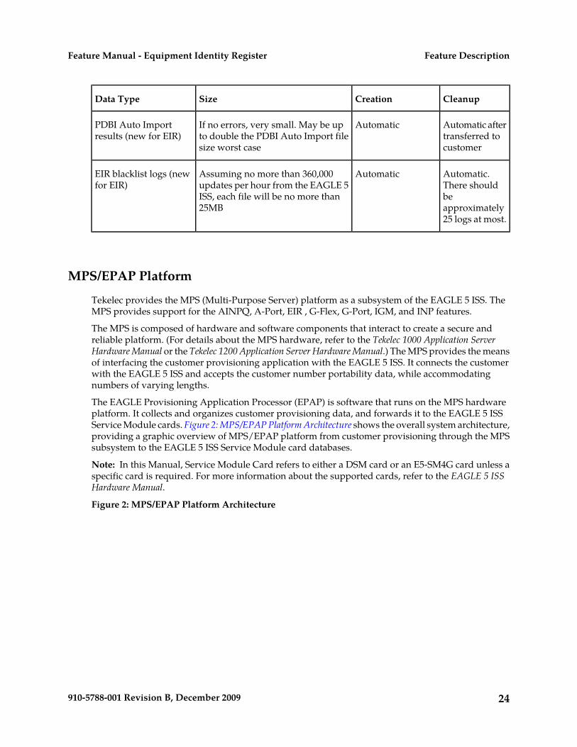
AutomaticIf no errors, very small. May be upto double the PDBI Auto Import filesize worst case
PDBI Auto Importresults (new for EIR)
Automatic.There should
AutomaticAssuming no more than 360,000updates per hour from the EAGLE 5
EIR blacklist logs (newfor EIR)
beISS, each file will be no more than25MB approximately
25 logs at most.
MPS/EPAP Platform
Tekelec provides the MPS (Multi-Purpose Server) platform as a subsystem of the EAGLE 5 ISS. TheMPS provides support for the AINPQ, A-Port, EIR , G-Flex, G-Port, IGM, and INP features.
The MPS is composed of hardware and software components that interact to create a secure andreliable platform. (For details about the MPS hardware, refer to the Tekelec 1000 Application ServerHardware Manual or the Tekelec 1200 Application Server Hardware Manual.) The MPS provides the meansof interfacing the customer provisioning application with the EAGLE 5 ISS. It connects the customerwith the EAGLE 5 ISS and accepts the customer number portability data, while accommodatingnumbers of varying lengths.
The EAGLE Provisioning Application Processor (EPAP) is software that runs on the MPS hardwareplatform. It collects and organizes customer provisioning data, and forwards it to the EAGLE 5 ISSService Module cards. Figure 2: MPS/EPAP Platform Architecture shows the overall system architecture,providing a graphic overview of MPS/EPAP platform from customer provisioning through the MPSsubsystem to the EAGLE 5 ISS Service Module card databases.
Note: In this Manual, Service Module Card refers to either a DSM card or an E5-SM4G card unless aspecific card is required. For more information about the supported cards, refer to the EAGLE 5 ISSHardware Manual.
Figure 2: MPS/EPAP Platform Architecture
24910-5788-001 Revision B, December 2009
Feature DescriptionFeature Manual - Equipment Identity Register
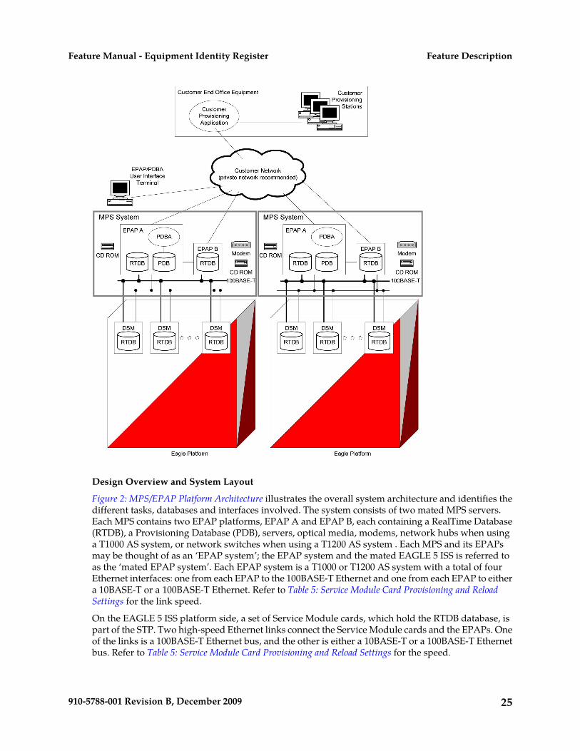
Design Overview and System Layout
Figure 2: MPS/EPAP Platform Architecture illustrates the overall system architecture and identifies thedifferent tasks, databases and interfaces involved. The system consists of two mated MPS servers.Each MPS contains two EPAP platforms, EPAP A and EPAP B, each containing a RealTime Database(RTDB), a Provisioning Database (PDB), servers, optical media, modems, network hubs when usinga T1000 AS system, or network switches when using a T1200 AS system . Each MPS and its EPAPsmay be thought of as an ‘EPAP system’; the EPAP system and the mated EAGLE 5 ISS is referred toas the ‘mated EPAP system’. Each EPAP system is a T1000 or T1200 AS system with a total of fourEthernet interfaces: one from each EPAP to the 100BASE-T Ethernet and one from each EPAP to eithera 10BASE-T or a 100BASE-T Ethernet. Refer to Table 5: Service Module Card Provisioning and ReloadSettings for the link speed.
On the EAGLE 5 ISS platform side, a set of Service Module cards, which hold the RTDB database, ispart of the STP. Two high-speed Ethernet links connect the Service Module cards and the EPAPs. Oneof the links is a 100BASE-T Ethernet bus, and the other is either a 10BASE-T or a 100BASE-T Ethernetbus. Refer to Table 5: Service Module Card Provisioning and Reload Settings for the speed.
25910-5788-001 Revision B, December 2009
Feature DescriptionFeature Manual - Equipment Identity Register

The RTDB database is provisioned and maintained through the EPAPs. EPAP A and EPAP B act asthe active EPAP and the standby EPAP. One link serves as the active link, and the other as the standbylink. At any given time, there is only one active EPAP and one active link. The database is provisionedthrough the active link by the active EPAP; the other EPAP provides redundancy.
In case of failure of the active EPAP, the standby EPAP takes over the role of active EPAP and continuesto provision the subscriber database. In the case where the active link fails, the active EPAP switchesto the standby link to continue provisioning the Service Module cards. The two Ethernet links are partof the DSM network.
Another 100BASE-T Ethernet link exists between the EPAPs; that link is called the EPAP sync network.
The major modules on the EPAP are:
• Service Module card provisioning module• Maintenance module• RTDB module• PDB module
The Service Module card provisioning module is responsible for updating subscriber databases onthe EAGLE 5 ISS Service Module cards using the Reliable Multicast Transport Protocol (RMTP)multicast. The maintenance module is responsible for the proper functioning of the EPAP platform.The PDB module is responsible for preparing and maintaining the Real Time Database, which is the“golden copy” of the subscriber database. The PDB module can run on one of the EPAPs of either ofthe mated EAGLE 5 ISSs.
Functional Overview
The main function of the MPS / EPAP platform is to provision the data from the customer networkto the Service Module cards on the EAGLE 5 ISS. Subscriber database records are continuously updatedfrom the customer network to the PDB. The PDB module communicates with the maintenance moduleand the RTDB task over a TCP/IP connection to provision the Service Module cards on the EAGLE 5ISS. The maintenance module is responsible for the overall stability and performance of the system.
It is possible for the current copy of the RTDB database on the Service Module cards to get out-of-syncdue to missed provisioning or card rebooting. Therefore, the RTDB on the EPAP contains a coherent,current copy of the subscriber database. The EPAP-Service Module card provisioning task sendsdatabase information out on the provisioning link. The Service Module cards act as the receivers andare reprovisioned.
EPAP/PDBA Overview
The EAGLE Provisioning Application Processor (EPAP) platform and the Provisioning DatabaseApplication (PDBA), coupled with the Provisioning Database Interface (PDBI) facilitate the userdatabase required for EAGLE 5 ISS EPAP-based features. The following functions are supported:
• Accept and store subscription data provisioned by the customer• Update and reload subscriber databases on the Service Module cards
The PDBA operates on the master Provisioning Database (PDB). The EPAP and PDBA are both installedon the MPS hardware platform.
The EPAP platform performs the following:
26910-5788-001 Revision B, December 2009
Feature DescriptionFeature Manual - Equipment Identity Register

• Maintains an exact copy of the real time database (RTDB) on the EPAP• Distributes the subscription database to the Service Module cards• Maintains a redundant copy of the RTDB database
The EPAP platform is a mated pair of processors (the upper processor, called EPAP A, and the lowerprocessor, EPAP B) contained in one frame.
During normal operation, information flows through the EPAP/PDBA software with no intervention.Subscription data is generated at one or more operations centers and is delivered to the PDBA througha TCP socket interface (PDBI). The PDBA software stores and replicates data on EPAP A on the matedEPAP system. The data is then transmitted by the EPAPs across a private network to the ServiceModule cards located in the EAGLE 5 ISS frame.
The primary interface to the PDBA consists of machine-to-machine messages. The interface is definedby Tekelec and is described in the Provisioning Database Interface Manual. Provisioning softwarecompatible with the EPAP socket interface can be created or updated using the interface described inthat manual.
Additionally, a direct user interface is provided on each EPAP to allow for configuration, maintenance,debugging, and platform operations. A direct user interface is also provided by the PDBA forconfiguration and database maintenance.
The MPS/EPAP is an open-systems platform and easily accommodates the required high provisioningrates. Compared to the traditional OAM platform, the persistent database and provisioning in an opensystems platform provides these benefits:
• Variety of hardware components and vendors• Availability of third party communication and database tools• Standard communication protocols• Availability of personnel with related experience
Each EPAP server maintains a copy of the Real Time Database (RTDB) in order to provision the EAGLE5 ISS Service Module cards. The EPAP server must comply with the hardware requirements in theMPS Hardware Manual. Figure 2: MPS/EPAP Platform Architecture illustrates the EPAP architecturecontained in the MPS subsystem.
Each EPAP has a dedicated optical media drive. One EPAP per EAGLE 5 ISS platform has a modemcapable of supporting remote diagnostics, configuration, and maintenance. These remote operationsare performed through EPAP login sessions and are accessible across the customer network as wellas through a direct terminal connection to the EPAP using an RS232 connection. Refer to the Tekelec1000 Application Server Hardware Manual or the Tekelec 1200 Application Server Hardware Manual fordetails about the hardware devices and network connections.
Subscriber Data Provisioning
Figure 3: Subscriber Data Provisioning Architecture (High Level) shows the current high-level view of thesubscriber data provisioning architecture. Only those parts of the EAGLE 5 ISS platform that arerelevant to subscriber data provisioning are shown. This section defines requirements for theProvisioning Database Interface (PDBI) between the EPAP and the operator's provisioning system(OPS). Provisioning clients connect to the EPAPs via the PDBI. This interface contains commands thatallow all of the provisioning and retrieving of subscription data. The PDBI is used for real-time
27910-5788-001 Revision B, December 2009
Feature DescriptionFeature Manual - Equipment Identity Register

provisioning of subscriber and network entity data only. Refer to the Provisioning Database InterfaceManual for more details.Figure 3: Subscriber Data Provisioning Architecture (High Level)
A pair of active/standby EPAP servers provides the interface between the Real Time Database (RTDB)of the EAGLE 5 ISS Service Module cards and the OPS. EPAP A is equipped with both the PDB(Provisioning Database) and the RTDB, and EPAP B has just the RTDB. An EPAP with just the RTDBmust be updated by the EPAP that has the PDB.
For more information about the EPAP, refer to the EPAP Administration Manual. For more informationabout the MPS hardware, refer to the Tekelec 1000 Application Server Hardware Manual or the Tekelec1200 Application Server Hardware Manual .
Distributed Administrative Architecture
This section describes, at a high level, the distributed administrative architecture for the EAGLE 5 ISS,including the EPAP.
Databases requiring high update and retrieval rates, such as the EPAP RTDB, are populated usingredundant Ethernet connections to Service Module cards from an EPAP MPS platform.
An EPAP consists of a combined Provisioning (MySQL) and Real Time Database (RTDB). TheProvisioning Database (PDB) responds to requests for updates by the active and standby RTDBs onboth mated EAGLE 5 ISSs. The active EPAP RTDB is responsible for initiating multi-cast updates of
28910-5788-001 Revision B, December 2009
Feature DescriptionFeature Manual - Equipment Identity Register

changed database records to the Service Module cards after the data has been committed to the EPAPdisks. Furthermore, the PDB may accept and commit more database updates while the RTDBs arecompleting their previous updates.
It is this overlapping of database updates, coupled with an RTDB transactional database engine andfast download time, that allows larger amounts of data at a time to be transferred from the PDB.Committing larger amounts of data at a time to the RTDB (versus a single update at a time) allowsfaster overall transaction rates to be achieved. The boundaries of the transaction rates become moreclosely related to cache size and disk cache flush time than the disk access time of a single update.Thus, successful completion of EPAP database updates only guarantees that the PDB has been updated,but it does not mean the RTDB has completed the update and sent the new subscription data to theService Module card.
The EPAP architecture contains a local provisioning terminal and a modem for remote access, as wellas other functions. A backup device can be used to back up or restore the provisioning database. Thelocal provisioning terminal is used to manually repair the standby EPAP RTDB or to turn the subscriberdatabase audit on or off. For additional information, refer to the Tekelec 1000 Application Server HardwareManual, Tekelec 1200 Application Server Hardware Manual, and EPAP Administration Manual.
EPAP (EAGLE Provisioning Application Processor)
As shown in Figure 2: MPS/EPAP Platform Architecture, a single MPS system contains two EPAP (EAGLEProvisioning Application Processor) servers. At any given time, only one actively communicates withthe Service Module cards. The other EPAP server is in standby mode. In addition, two MPS systemscan be deployed in a mated-pair configuration.
The primary purpose of the EPAP systems is to maintain the RTDB and PDB and to download copiesof the RTDB to the Service Module cards on the EAGLE 5 ISS.
The PDB on the active EPAP receives subscription data from the customer network through the PDBI,the external source of provisioning information. The PDBA continually updates the active EPAP’sPDB. The PDB uses MySQL database software. Once an update is applied to the active PDB, it is sentto the RTDBs on the active and standby EPAPs.
Both the active and standby EPAPs maintain copies of the RTDB. Periodically, the Service Modulecard polls the active EPAP RTDB for any new updates. The active EPAP downloads the updates tothe Service Module for its own resident copy of the RTDB.
In a mated-pair configuration, there are two mated MPS Systems, as shown in Figure 2: MPS/EPAPPlatform Architecture. The PDB on the active EPAP automatically updates the PDB on the mate platform.The PDB on the mate platform then updates its EPAP RTDBs, which in turn update the RTDBs on theassociated Service Module cards.
Provisioning of the EAGLE 5 ISS’s Service Module cards is performed through two interfaces, usingtwo different sets of commands. Provisioning is accomplished by the STP updates from EAGLE 5 ISSterminals and by updates from the customer’s external provisioning system. This system of dualprovisioning is illustrated in Figure 4: Database Administrative Architecture.Figure 4: Database Administrative Architecture
29910-5788-001 Revision B, December 2009
Feature DescriptionFeature Manual - Equipment Identity Register

Service Module Cards
From 1 to 25 Service Module cards can be provisioned with one or more EPAP-related features enabled.EPAP-related features require that all Service Module cards contain 4 GB of memory. Figure 4: DatabaseAdministrative Architecture illustrates each Service Module card having two Ethernet links, the mainService Module network on the 100BASE-T link and the backup Service Module network . Refer toTable 5: Service Module Card Provisioning and Reload Settings for the link speed. The Service Modulecards run the VSCCP software application.
The Service Module Ethernet ports are linked to the EPAP system to receive the downloaded RealTime database (RTDB). Multiple Service Module cards provide a means of load balancing in high-trafficsituations. The RTDB on the Service Module card is in a format that facilitates rapid lookups.
Though the Service Module card copies of the RTDB are intended to be identical, the various databasesmay not be identical at all times for the following reasons:
• When a Service Module card is initialized, the card downloads the current copy of the databasefrom the EPAP. While that card is being loaded, it cannot receive new updates that have arrivedat the EPAP since reload began..
• Card databases can become out-of-sync with the EPAP RTDB when the EPAP receives updatesfrom its provisioning source, but it has not yet sent the updates down to the Service Module cards.Updates are applied to the Provisioning Database (PDB) as they are received.
30910-5788-001 Revision B, December 2009
Feature DescriptionFeature Manual - Equipment Identity Register

Two possible scenarios contribute to a condition where a Service Module card may not have enoughmemory to hold the entire database:
• The database is downloaded successfully to the Service Module card, but subsequent updateseventually increase the size of the database beyond the capacity of the Service Module card memory.In this situation, it is desirable for EPAP-related features to continue processing transactions, eventhough the database might not be up-to-date.
• When a Service Module card is booted and it is determined then that the card does not have enoughmemory for the entire database, the database is not loaded on that card. Each Service Module cardis responsible for recognizing and reporting its out-of-memory conditions by means of alarms.
Overview of EPAP to Service Module Card Communications
Before discussing Service Module card status reporting or EPAP status reporting, it is helpful tounderstand the communications between the Service Module cards and the EPAP in broad terms.
• UDP - sending Service Module card status messages
The Service Module cards and EPAPs create a UDP (User Datagram Protocol) socket which is usedfor status messages. One of the last things a Service Module card does when it is initialized is tosend a status message to the EPAP, containing the Service Module ID, database level, and memorysize. The EPAP maintains tables containing the last known status of each Service Module card.EPAP uses these to determine whether or not the Service Module card needs to download thedatabase.
• IP - reporting EPAP maintenance data
The Service Module cards create an TCP socket when they are initialized, and listen for connectionrequests. During initialization or after a loss of connectivity, the active EPAP chooses one of theService Module cards and issues a Connect to establish the TCP/IP connection with that ServiceModule card (referred to as the primary Service Module). The purpose of this link is to provide apath for reporting EPAP alarms and to forward maintenance blocks to the Service Module card.
• IP Multicast - downloading GSM database
Because of the large size of the database and the need to download it quickly on up to 25 ServiceModule cards, EPAP-related features use a technique known as IP multicasting. This technique isbased on Reliable Multicast Transport Protocol-II (RMTP-II), a product of GlobalcastCommunications. IP multicasting downloads the RTDB and database updates to all of the ServiceModule cards simultaneously.
The administration of IP multicasting is based on the concept of a “tree”, or stream of data, whichis constantly being broadcast by the EPAP. Service Module cards that need to download the realtime database or to receive database updates “join the tree”. Service Module cards can also “leavethe tree”, typically when the database fills their available memory.
Service Module Card Provisioning and ReloadOne of the core functions of the EPAP is to provision the Service Module cards with the Real TimeDatabase (RTDB) updates. In order to provide redundancy for this feature, separate RMTP channelsare created on each interface from each EPAP:
31910-5788-001 Revision B, December 2009
Feature DescriptionFeature Manual - Equipment Identity Register

Table 5: Service Module Card Provisioning and Reload Settings
T1200
Running bothDSM andE5-SM4G cards
T1200
Running OnlyE5-SM4G cards
T1200
Running OnlyDSM cards
T1000RMTP Channel
100BASE-T100BASE-T100BASE-T100BASE-TEPAP A, Link A
(on the main DSMnetwork)
10BASE-T100BASE-T10BASE-T10BASE-TEPAP A, Link B
(on the backupDSM network)
100BASE-T100BASE-T100BASE-T100BASE-TEPAP B, Link A
(on the main DSMnetwork)
10BASE-T100BASE-T10BASE-T10BASE-TEPAP B, Link B
(on the backupDSM network)
Note: Full duplex mode is supported only when running all E5-SM4G cards on the T1200. In allother cases, half duplex mode is supported.
Provisioning and other data is broadcast on one of these channels to all of the Service Module cards.Provisioning is done by database level in order to leave tables coherent between updates.
The Service Module cards do the following:
• Detect the need for incremental updates and send a status message to the EPAP.• Discriminate between the various streams according to the database level contained in each message
and accept updates based on the Service Module card database level.
Service Module Card Reload ModelService Module cards may require a complete database reload in the event of reboot or loss ofconnectivity for a significant amount of time. The EPAP provides a mechanism to quickly load anumber of Service Module cards with the current database. The database on the EPAP is large andmay be updated constantly. The database sent to the Service Module card or cards will likely be missingsome of these updates making it corrupt, in addition to being "back level."
EPAP Continuous Reload
It is important to understand how the EPAP handles reloading of multiple Service Module cards fromdifferent starting points. Reload begins when the first Service Module card requires it. Records are
32910-5788-001 Revision B, December 2009
Feature DescriptionFeature Manual - Equipment Identity Register

read sequentially from the Real Time Database (RTDB) from an arbitrary starting point, wrappingback to the beginning. If another Service Module card requires reloading at this time, it uses the existingrecord stream and notifies the Service Module card provisioning task of the first record it read. Thiscontinues until all Service Module cards are satisfied.
Service Module Card Database Levels and Reloading
The current database level when the reload started is of special importance during reload. When aService Module card detects that the last record has been received, it sends a status message back tothe EPAP indicating the database level at the start of reload. This action starts incremental loading.The Service Module card continues to reload until it is completely caught up with the current level ofthe RTDB. As database records are sent to the Service Module cards during reload, normal provisioningcan change those records. All records changed between the start and end of reloading must beincrementally loaded before the database is coherent and usable by the Service Module card.
The following terminology is used here for the stages of database reload for a given Service Modulecard.
• Stage 1 loading: The database is being copied record for record from the golden RTDB in the EPAPto the Service Module card RTDB. The database is incoherent during stage 1 loading.
• Incremental update: The database is receiving all of the updates missed during stage 1 loading orsome other reason (e.g., network outage, processor limitation, lost communication, etc.). Thedatabase is coherent, but back-level during incremental update.
• Current: The database is receiving current updates from the Service Module card provisioningtask.
• Coherent: The database is at a whole database level, that is, not currently updating records belongingto a database level.
EPAP Status and Error Reporting via Maintenance BlocksThe EPAPs forward all status and error messages to the Service Module cards in maintenance blocks.Maintenance blocks are asynchronously sent whenever the EPAP has something to report. Themaintenance blocks eventually update EPAP Device Control Blocks (DCBs) located on the EAGLE 5ISS. The DCBs provide the status information that is received when a rept-stat-mps command isissued.
Network Connections
Several customer and Tekelec-installed private networks are required to support the provisioning ofsubscription data. These networks are:
• Customer Provisioning Network• EPAP Sync Network• DSM Networks• Dial-Up PPP Network
The following discussion is an overview of these private networks. It expands on the networks in thearchitecture diagram shown in Figure 5: Customer Provisioning Network. (For details about configuringthese networks, refer to the EPAP Administration Manual.)
33910-5788-001 Revision B, December 2009
Feature DescriptionFeature Manual - Equipment Identity Register

Customer Provisioning Network
The customer network carries the following traffic:Mai
• Customer queries and responses to the PDB via the PDBI from the customer provisioning network• Updates between PDBs of a mated EAGLE 5 ISS pair• Updates between a PDB on one EAGLE 5 ISS and RTDBs on a mated EAGLE 5 ISS• PDBA import/export (file transfer) traffic• Traffic from a PDBA reloading from its mate• EPAP and PDBA user interface traffic.
A typical customer network is shown in Figure 5: Customer Provisioning Network.Figure 5: Customer Provisioning Network
34910-5788-001 Revision B, December 2009
Feature DescriptionFeature Manual - Equipment Identity Register

Although a dedicated network is recommended, it is possible that unrelated customer traffic can usethe network as well. The determination, either to have a dedicated network or to allow other customertraffic, should be based on available external Ethernet bandwidth and network performanceconsiderations.
EPAP Sync Network
The T100 EPAP sync network carries RTDB and maintenance application traffic between active andstandby EPAP servers on an MPS system. It synchronizes the contents of the RTDBs of both EPAP Aand B. The EPAP Sync network is a single Ethernet connection between EPAP A and EPAP B runningat 100BASE-T, as shown in Figure 6: EPAP Sync Network. The T1200 EPAP Sync network is truncatedwith the EPAP's back up DSM connection and communicates through the switch.Figure 6: EPAP Sync Network
DSM Networks
The DSM networks are shown in Figure 7: DSM Networks. They carry provisioning data from the activeEPAP RTDB to the Service Module cards. They also carry reload and maintenance traffic to the ServiceModule cards.
The DSM networks consist of two Ethernet networks: the main DSM network running at 100BASE-T,and the backup DSM network running at either 10BASE-T or 100Base-T. Refer to Table 5: Service ModuleCard Provisioning and Reload Settings for the link speed. Both Ethernet networks connect EPAP A andEPAP B with every Service Module card on a single EAGLE 5 ISS platform.Figure 7: DSM Networks
35910-5788-001 Revision B, December 2009
Feature DescriptionFeature Manual - Equipment Identity Register

Maintenance information is sent from the active EPAP to an arbitrarily selected Service Module card.The selected Service Module card is known as the primary Service Module card. Static information isexchanged across this interface at initialization, and dynamic information is exchanged on occasion.
While much of the traditional OAM provisioning and database functionality is implemented on theEPAP, the maintenance reporting mechanism is still the OAM.
The first and second octets of the EPAP network addresses for this network are 192.168. (The first twooctets for private class C networks are defined in RFC 1918.)
The third octet is customer specifiable for each DSM network. It is important to select values that donot interfere with the customer's network addressing scheme.
The fourth octet of the address is specified as follows:
• If the EPAP is configured as “EPAP A”, the fourth octet has a value of 100.• If the EPAP is configured as “EPAP B”, the fourth octet has a value of 200.
Table 6: EPAP IP Addresses in the DSM Network summarizes the contents of each octet.
Table 6: EPAP IP Addresses in the DSM Network
ValueOctet
‘192’1
‘168’2
One customer-provisioned value for DSM network A, and another for DSM networkB
3
‘100’ for EPAP A‘200’ for EPAP B4
36910-5788-001 Revision B, December 2009
Feature DescriptionFeature Manual - Equipment Identity Register

Dial-Up PPP Network
The dial-up PPP network allows multiple user-interface sessions to be established with the EPAP. Thenetwork connects a remote EPAP/PDBA user interface terminal with the EPAP in the EAGLE 5 ISS’sMPS subsystem. The dial-up PPP network is illustrated in Figure 8: Dial-Up PPP Network.Figure 8: Dial-Up PPP Network
Serviceability Hints
The following hints are offered to aid in the serviceability of EIR databases:
• Mated Application Considerations• Entity Point Codes and Routes
Mated Application ConsiderationsAn EPAP-administered entity data can possibly become out-of-sync with the EAGLE 5 ISS matedapplication table because the creation of entity point codes (and/or subsystem numbers) in the matedapplication table is not performed at database administration time.
If this mismatch is discovered in real-time operations, a UIM message (such as “SCCP did not route- DPC not in MAP tbl” or “SCCP did not route - SS not in MAP tbl”) is sent to the EAGLE 5 ISSmaintenance terminal. This message means the MSU was discarded.
For this reason, it is recommended that the entity (SP or RN) not be administered until the entity pointcode (and/or subsystem number) has been entered into the EAGLE 5 ISS mated application (MAP)table.
37910-5788-001 Revision B, December 2009
Feature DescriptionFeature Manual - Equipment Identity Register

Entity Point Codes and RoutesVerification that an entity point code exists in the route table and has a route is not performed atdatabase administration time. Therefore, it is possible for the EPAP entity data to be out-of-sync withthe EAGLE 5 ISS route table.
If an out-of-sync condition is discovered during real-time operation, a UIM is sent to the EAGLE 5 ISSmaintenance terminal, indicating one of these conditions:
• Destination point code is not in the route table.• Destination point code exists in the route table but is not assigned a route.• Destination point code exists in the route table and has been assigned a route, but it is out of service.
38910-5788-001 Revision B, December 2009
Feature DescriptionFeature Manual - Equipment Identity Register

Chapter
3EAGLE 5 ISS EIR Commands
This chapter describes the new or updatedcommands that support the EIR faeture. It provides
Topics:
• Introduction.....40 some sample reports and explanations ofappropriate comand usage.• EAGLE 5 ISS Commands for EIR.....40
39910-5788-001 Revision B, December 2009

Introduction
This chapter describes the Commands for maintenance, measurements, and administration of the EIRfeatures. EAGLE 5 ISS EIR commands provide for the provisioning, operations, and maintenanceactivities of the EAGLE 5 ISS Service Module cards and associated network connections.
EAGLE 5 ISS Commands for EIR
This section includes the EAGLE 5 ISS commands that are either entirely new or modified for the EIRfeature. This chapter contains a brief description of the functions they provide and appropriate examplesof their use. User commands are listed in Table 7: Commands for EAGLE 5 ISS EIR.
The command examples in this chapter illustrate the requirements and provide suggestions for suitablenames and output. Complete descriptions of these commands, however, are shown in detail in theCommands Manual, including parameter names, valid values, and output examples for the commands.
Table 7: Commands for EAGLE 5 ISS EIR
EAGLE 5 ISS Commands for EIR Feature
rept-stat-sysent-srvselchg-ss-applalw-card
rept-stat-trblent-ss-appldlt-mapalw-map-ss
rtrv-ctrl-featinh-carddlt-cardchg-ctrl-feat
rtrv-cardinh-map-ssdlt-srvselchg-feat
rtrv-gsmoptsrept-ftp-measdlt-ss-applchg-gsmopts
rtrv-measoptsrept-stat-almdlt-sidchg-measopts
rtrv-sidrept-stat-dbenable-ctrl-featchg-map
rtrv-srvselrept-stat-mpsent-cardchg-sid
rtrv-ss-applrept-stat-sccpent-mapchg-srvsel
40910-5788-001 Revision B, December 2009
EAGLE 5 ISS EIR CommandsFeature Manual - Equipment Identity Register

EAGLE 5 ISS chg-feat Commands
The chg-feat command administers the EIR feature. It has two variations, each of which is describedin the following: chg-feat and rtrv-feat. For further details on these commands, please refer tothe Commands Manual.
• chg-feat: Change Feature Status Command – The chg-feat command activates optional featuresavailable for the system. Features can only be turned on. Once the feature is activated, it cannot beturned off. The chg-feat command turns on the EIR capabilities and enforces mutual exclusionbetween LNP and EIR. The GTT feature is a prerequisite for EIR. A command example follows.
chg-feat: eir=on
eir= {on,off}
• rtrv-feat: Retrieve Feature Status Command – The rtrv-feat command displays the featurestatus for the EIR feature. An example of command output follows.
tekelecstp 99-04-02 14:23:37 EAGLE 35.0.0 EAGLE FEATURE LIST GTT = on GWS = off NRT = off LAN = off CRMD = off SEAS = off LFS = off MTPRS = off LNP = off FAN = off DSTN4000 = off WNP = off CNCF = off LNP12MIL = off TLNP = off SCCPCNV = off TCAPCNV = off PLNP = off NCR = off ITUMTPRS = off SLSOCB = off EGTT = off IPISUP = on DYNRTK = on PVGTT = off PRFXDLGT = on MPC = on EIR = on ITUDUPPC = on GFLEX = off GPORT = on;
EAGLE 5 ISS EIR System Options Commands
The EIR system options (gsmopts) commands are used to change and report on the values of one ormore of the STP node level processing option indicators maintained in the STP option tables. All valuesare assigned initially to system defaults at STP installation time, and they can be updated later usingthe chg-stpopts command.
Three parameters were added for EIR.
The first parameter (EIRIMSICHK) is used to indicate whether or not the IMSI will be used whendetermining if an IMEI is to be Black Listed. If this parameter is on and an IMEI is found on the BlackList, then the corresponding IMSI is retrieved. If the IMSI found in the message matches the IMSIretrieved, then the IMEI is considered to be on the White List. If the IMSI's do not match or is not found,then the IMEI will remain Black Listed.
The second parameter (EIRRSPTYPE) is used to determine the EIR Response Type. The ResponseType is used to determine how the lists are searched. Refer to Table 8: Individual IMEI List DeterminationTable to determine the EIR Response Type.
41910-5788-001 Revision B, December 2009
EAGLE 5 ISS EIR CommandsFeature Manual - Equipment Identity Register

Table 8: Individual IMEI List Determination Table
MSU ResultEquipmentStatus
LOG EntryResult
LOGEntry
ResultType
IMSIMatch
IMSICheck
WhiteList
GrayList
BlackList
0White with IMSIOverride
NDCYYNNY
1Black with IMSIFailed
Y1NYNNY
1Black with IMSIFailed
Y2NYNNY
RE=7UnknownN3NYNNY
1BlackY1DCNYNY
1BlackY2DCNYNY
1BlackY3DCNYNY
0White with IMSIOverride
N1YYYNY
0White with IMSIOverride
N2YYYNY
0White with IMSIOverride
N3YYYNY
1BlackY1DCNNYY
1BlackY2DCNNYY
RE=7UnknownN3DCNNYY
0White with IMSIOverride
Y1YYNYY
0White with IMSIOverride
Y2YYNYY
42910-5788-001 Revision B, December 2009
EAGLE 5 ISS EIR CommandsFeature Manual - Equipment Identity Register

MSU ResultEquipmentStatus
LOG EntryResult
LOGEntry
ResultType
IMSIMatch
IMSICheck
WhiteList
GrayList
BlackList
0White with IMSIOverride
Y3YYNYY
2GrayY1DCYNYN
2GrayY2DCYNYN
RE=7Unknown3DCYNYN
2GrayY1DCDCYYN
2GrayY2DCDCYYN
2GrayY3DCDCYYN
0WhiteN1DCDCYNN
0WhiteN2DCDCYNN
0WhiteN3DCDCYNN
0WhiteN1DCDCNNN
RE=7UnknownN2DCDCNNN
RE=7UnknownN3DCDCNNN
1BlackY1DCNYYY
1BlackY2DCNYYY
1BlackY3DCNYYY
0White with IMSIOverride
N1YYYYY
0White with IMSIOverride
N2YYYYY
43910-5788-001 Revision B, December 2009
EAGLE 5 ISS EIR CommandsFeature Manual - Equipment Identity Register

MSU ResultEquipmentStatus
LOG EntryResult
LOGEntry
ResultType
IMSIMatch
IMSICheck
WhiteList
GrayList
BlackList
0White with IMSIOverride
N3YYYYY
1Black with IMSIFailed
N1NYYYY
1Black with IMSIFailed
N2NYYYY
1Black with IMSIFailed
N3NYYYY
The third parameter (EIRGRSP) is used to turn on the EIR Global Response Type. The Global ResponseType is used to override the response that is sent back to the MSC. The default is set to OFF . Whenset to OFF , the normal list logic is applied to the IMEI. If the Global Response Type is set to somethingother than OFF , then there is no list logic processing and the corresponding response is sent to theMSC. Refer to the Commands Manual for details of this command.
• chg-gsmopts: Change EIR System Options Command – The chg-gsmopts command changesEIR-specific system options in the database. This command updates the GSMOPTS table. Thedefault parameters are always overwritten when specified.
Table 9: chg-gsmopts Parameters - Class = DATABASE
DescriptionRangeOptional/MandatoryParameter
EIR Global Response statusOFF, WHITELST, GRAYLST,BLKLST, UNKNOWN
OptionalEIRGRSP
EIR Response TypeTYPE1, TYPE2, TYPE3OptionalEIRRSPTYPE
EIR IMSI Check statusOFF or ONOptionalEIRIMSICHK
Command examples follow.
chg-gsmopts:eirimsichk=on:eirrsptype=type1chg-gsmopts:eirimsichk=on:eirrsptype=type2:eirgrsp=blklst
• rtrv-gsmopts: Retrieve EIR System Options Command – The rtrv-gsmopts command displaysall EIR-specific system options from the database.
The following EIR options are displayed.
GSM OPTIONS
44910-5788-001 Revision B, December 2009
EAGLE 5 ISS EIR CommandsFeature Manual - Equipment Identity Register

----------------------- EIRGRSP = BLKLST EIRRSPTYPE = TYPE2 EIRIMSICHK = ON
EAGLE 5 ISS EIR Service Selector Commands
The EIR service selector (srvsel) commands are used to provision, remove, change, and report on theapplicable service selectors required to change a service entry for DSM services. These commandsprovide some flexibility when provisioning the type of messages that require EIR processing. Thereare four variants, each of which is described in the following sections: ent-srvsel, chg-srvsel,dlt-srvsel, and rtrv-srvsel. For further details on the EAGLE 5 ISS service selector commands(such as command rules and output format), refer to the Commands Manual.
• ent-srvsel: Enter EIR Service Selectors Command – The ent-srvsel command specifies thatthe applicable EIR service selectors indicating EIR processing are required. The available parametersfollow:
Table 10: ent-srvsel Parameters - Class = DATABASE
DescriptionRangeOptional/MandatoryParameter
Global Title Indicator2, 4MandatoryGTII, GTIN,GTIN24
GSM serviceeirMandatorySERV
Subsystem number0-255, *MandatorySSN
Translation Type0-255MandatoryTT
Nature Of Address Indicatorsub, rsvd, natl, intlOptionalNAI
NAI Value0-127OptionalNAIV
Numbering Plane164, generic, x121, f69, e210,e212, e214, private
OptionalNP
Numbering Plan Value0-15OptionalNPV
• chg-srvsel: Change EIR Service Selector Command – The chg-srvsel command specifies theapplicable EIR selectors required to change an existing EIR selector entry. The available parametersfollow:
45910-5788-001 Revision B, December 2009
EAGLE 5 ISS EIR CommandsFeature Manual - Equipment Identity Register

Table 11: chg-srvsel Parameters - Class = DATABASE
DescriptionRangeOptional/MandatoryParameter
Global Title Indicator2, 4MandatoryGTII, GTIN,GTIN24
Subsystem number0-255, *MandatorySSN
Translation Type0-255MandatoryTT
Nature Of Address Indicatorsub, rsvd, natl, intlOptionalNAI
NAI Value0-127OptionalNAIV
Numbering Plane164, generic, x121, f69, e210,e212, e214, private
OptionalNP
Numbering Plan Value0-15OptionalNPV
New GSM servicegport, gflex, inpq, inpmr, eirMandatoryNSERV
• dlt-srvsel: Delete EIR Service Selector Command – The dlt-srvsel command deletes a EIRservice selector. The available parameters follow:
Table 12: dlt-srvsel Parameters - Class = DATABASE
DescriptionRangeOptional/MandatoryParameter
Global Title Indicator2, 4MandatoryGTII, GTIN,GTIN24
Translation Type0-255MandatoryTT
Subsystem number0-255, *MandatorySSN
Nature Of Address Indicatorsub, rsvd, natl, intlOptionalNAI
NAI Value0-127OptionalNAIV
Numbering Plane164, generic, x121, f69, e210,e212, e214, private
OptionalNP
46910-5788-001 Revision B, December 2009
EAGLE 5 ISS EIR CommandsFeature Manual - Equipment Identity Register
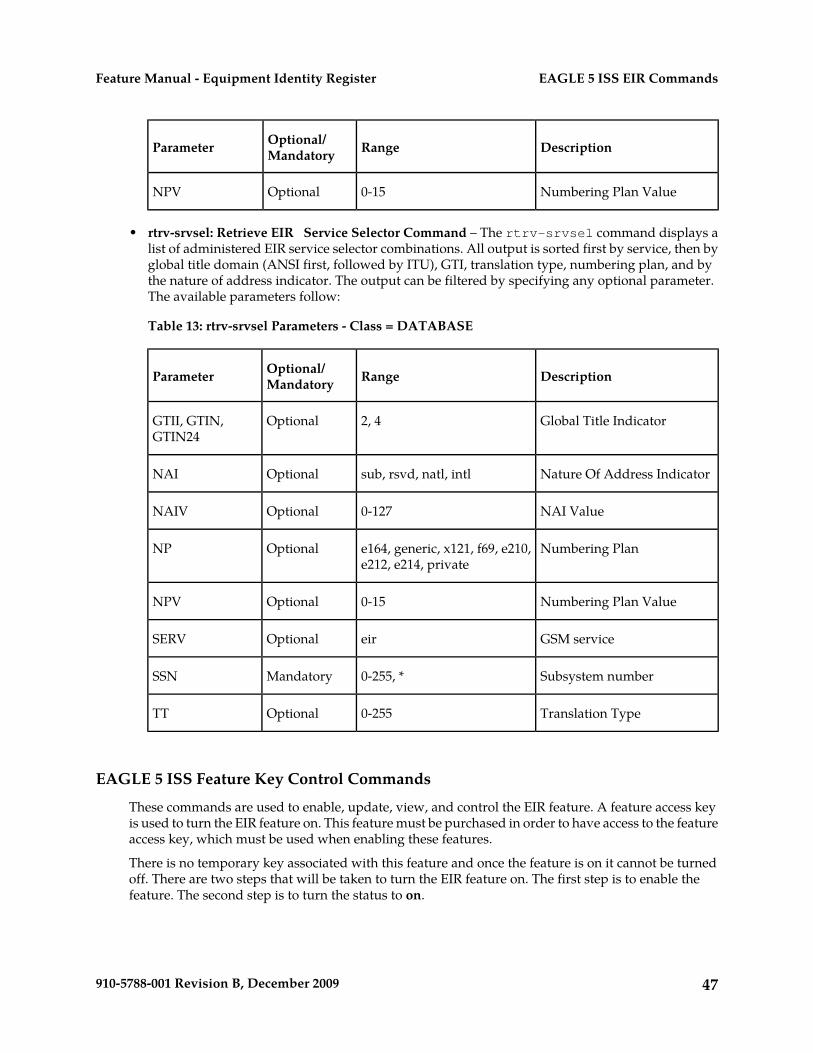
DescriptionRangeOptional/MandatoryParameter
Numbering Plan Value0-15OptionalNPV
• rtrv-srvsel: Retrieve EIR Service Selector Command – The rtrv-srvsel command displays alist of administered EIR service selector combinations. All output is sorted first by service, then byglobal title domain (ANSI first, followed by ITU), GTI, translation type, numbering plan, and bythe nature of address indicator. The output can be filtered by specifying any optional parameter.The available parameters follow:
Table 13: rtrv-srvsel Parameters - Class = DATABASE
DescriptionRangeOptional/MandatoryParameter
Global Title Indicator2, 4OptionalGTII, GTIN,GTIN24
Nature Of Address Indicatorsub, rsvd, natl, intlOptionalNAI
NAI Value0-127OptionalNAIV
Numbering Plane164, generic, x121, f69, e210,e212, e214, private
OptionalNP
Numbering Plan Value0-15OptionalNPV
GSM serviceeirOptionalSERV
Subsystem number0-255, *MandatorySSN
Translation Type0-255OptionalTT
EAGLE 5 ISS Feature Key Control Commands
These commands are used to enable, update, view, and control the EIR feature. A feature access keyis used to turn the EIR feature on. This feature must be purchased in order to have access to the featureaccess key, which must be used when enabling these features.
There is no temporary key associated with this feature and once the feature is on it cannot be turnedoff. There are two steps that will be taken to turn the EIR feature on. The first step is to enable thefeature. The second step is to turn the status to on.
47910-5788-001 Revision B, December 2009
EAGLE 5 ISS EIR CommandsFeature Manual - Equipment Identity Register

Additional verifications are done to ensure the correct hardware is present in the system. These checksinclude verifying that the GTT bit is on and that there are no SCCP GLP cards provisioned. Refer tothe Commands Manual for details of this command.
The part number 893012301 is used to enable EIR feature on the EAGLE 5 ISS.
• enable-ctrl-feat: Enable Control Feature Command – The enable-ctrl-feat command is usedfor the permanent enabling of the EIR feature. An example of the command using the EIR partnumber follows:enable-ctrl-feat:partnum=893012301:fak=<feature access key>
• chg-ctrl-feat: Change Control Feature Command – The chg-ctrl-feat command is used toturn on the EIR feature. The EIR feature cannot be enabled if any TSMs are in the system.chg-ctrl-feat:partnum=893012301:status=on
• rtrv-ctrl-feat: Retrieve Control Feature Command – The rtrv-ctrl-feat command is used todisplay the status of the features (on/off) and to show the trial period remaining if temporarilyenabled. An example output follows:
The following features have been permanently enabled: Feature Name Partnum Status Quantity IPGWx Signaling TPS 893012805 on 2000 ISUP Normalization 893000201 on ---- Command Class Management 893005801 on ---- Prepaid SMS Intercept Ph1 893006701 on ---- Intermed GTT Load Sharing 893006901 on ---- G-Port Circ Route Prevent 893007001 on ---- XGTT Table Expansion 893006101 on 400000 XMAP Table Expansion 893007710 on 3000 Large System # Links 893005910 on 2000 Routesets 893006401 on 6000 EAGLE5 Product 893007101 off ---- EAGLE Product 893007201 off ---- IP7 Product 893007301 off ---- Network Security Enhance 893009101 off ---- HC-MIM SLK Capacity 893011801 on 64 EIR 893012301 on ---- EAGLE OA&M IP Security 893400001 off ---- SCCP Conversion 893012001 on ----
The following features have been temporarily enabled: Feature Name Partnum Status Quantity Trial Period Left G-Port Circ Route Prevent 893007001 On ---- 20 days 8 hrs 57 mins
The following features have expired temporary keys: Feature Name Part Num OnOffFeatV 893492401;
Maintenance and Measurements User Interface Commands
This section provides a description of the user interface for maintenance and measurements for theEIR feature. The commands that follow allow provisioning, operations, and maintenance activitiesfor Service Module cards.
The command examples shown illustrate the requirements and provide suggestions for suitable namesand output. The commands are described in detail in the Commands Manual, where the actual parameternames, valid values, and output for the commands are provided.
48910-5788-001 Revision B, December 2009
EAGLE 5 ISS EIR CommandsFeature Manual - Equipment Identity Register

Commands described here include:
• chg-measopts• chg-sid / dlt-sid• ent-map / chg-map / dlt-map• ent-ss-appl / chg-ss-appl / dlt-ss-appl / rtrv-ss-appl• rept-stat-sys• rept-stat-sccp• rept-stat-mps• rept-ftp-meas• rtrv-measopts / chg-measopts• rept-stat-trbl• rept-stat-alm• rept-stat-db• inh-card / alw-card• ent-card• chg-gpl / act-gpl / rtrv-gpl / rept-stat-gpl / copy-gpl• inh-alm / unhb-alm
rept-stat-sys
This command is modified to output the status of the EIR subsystem. The remainder of the report isunchanged. Refer to the Commands Manual for details of this command.
A sample output follows:
eagle10605 01-07-25 02:32:46 EST Rel 35.0.0-49.10.0 MAINTENANCE STATUS REPORT Maintenance Baseline established. Routing Baseline established. SCCP Baseline established. ALARMS: CRIT= 9 MAJR= 10 MINR= 3 INH= 2 OAM 1113 IS-NR Active INH= 0 OAM 1115 IS-NR Standby INH= 0 LIM CARD IS-NR= 3 Other= 0 INH= 0 SCCP CARD IS-NR= 1 Other= 0 INH= 0 GLS CARD IS-NR= 0 Other= 0 INH= 0 SLAN CARD IS-NR= 0 Other= 0 INH= 0 EMDC CARD IS-NR= 2 Other= 0 INH= 0 MCPM CARD IS-NR= 2 Other= 0 INH= 0 IMT IS-NR= 2 Other= 0 HMUX IS-NR= 2 Other= 0 INH= 0 HIPR IS-NR= 2 Other= 0 INH= 0 SLK IS-NR= 0 Other= 6 INH= 0 DLK IS-NR= 0 Other= 0 INH= 0 LINK SET IS-NR= 0 Other= 4 INH= 0 NDC IP LK IS-NR= 4 Other= 0 INH= 0 MCPM IP LK IS-NR= 2 Other= 0 INH= 0 SS7 DPC IS-NR= 0 Other= 6 INH= 0 CLUST DPC IS-NR= 0 Other= 1 INH= 0 XLIST DPC IS-NR= 0 Other= 0 DPC SS Actv = 0 Other= 0
49910-5788-001 Revision B, December 2009
EAGLE 5 ISS EIR CommandsFeature Manual - Equipment Identity Register

SEAS SS IS-NR= 0 Other= 0 LSMS SS IS-NR= 0 Other= 0 LSMS Conn IS-NR= 0 Other= 0 INH= 0 NDC SS IS-NR= 1 Other= 0 NDC Q.3 IS-NR= 0 Other= 2 INH= 1 TERMINAL IS-NR= 2 Other= 14 INH= 0 MPS IS-NR= 2 Other= 0 EIR SS IS-NR= 1 Other= 0
rept-stat-sccp
The command handling and scroll area output for the rept-stat-sccp command includes theService Module card. The loc parameter displays detailed card traffic statistics. This command ismodified to output EIR Subsystem status, EIR status (for card) and EIR statistics for the summary and"loc=XXXX" report output. Also added to reports is CPU usage related to EIR. Refer to the CommandsManual for details of this command.
rept-stat-mps
Command output for the various reports of this command are modified to output the EIR status forcards and Primary card status. The check for MPS-related features that are required to be on for thisreport are extended to the EIR feature. Refer to the Commands Manual for details of this command.
A sample output follows:
rlghncxa03w 09-01-07 10:23:93 EST EAGLE 40.0.0 VERSION PST SST ASTEPAP A 027-015-000 IS-NR Active -----CRITICAL PLATFORM ALARM DATA = No AlarmsMAJOR PLATFORM ALARM DATA = No AlarmsMINOR PLATFORM ALARM DATA = No AlarmsCRITICAL APPLICATION ALARM DATA = No AlarmsMAJOR APPLICATION ALARM DATA = No AlarmsMINOR APPLICATION ALARM DATA = No Alarms ALARM STATUS = No Alarms
VERSION PST SST ASTEPAP B 027-015-000 OOS-MT Fault StandbyCRITICAL PLATFORM ALARM DATA = No AlarmsMAJOR PLATFORM ALARM DATA = No AlarmsMINOR PLATFORM ALARM DATA = No AlarmsCRITICAL APPLICATION ALARM DATA = No AlarmsMAJOR APPLICATION ALARM DATA = No AlarmsMINOR APPLICATION ALARM DATA = No Alarms ALARM STATUS = No Alarms
CARD PST SST EIR STAT 1106 P IS-NR Active ACT 1201 IS-ANR Active SWDL 1205 OOS-MT-DSBLD Manual ------- 1302 OOS-MT Isolated ------- 1310 IS-ANR Standby SWDL
CARD 1106 ALARM STATUS = No Alarms DSM PORT A: ALARM STATUS = No Alarms DSM PORT B: ALARM STATUS = No AlarmsCARD 1201 ALARM STATUS = No Alarms DSM PORT A: ALARM STATUS = No Alarms DSM PORT B: ALARM STATUS = No AlarmsCARD 1205 ALARM STATUS = No Alarms DSM PORT A: ALARM STATUS = No Alarms DSM PORT B: ALARM STATUS = No Alarms
50910-5788-001 Revision B, December 2009
EAGLE 5 ISS EIR CommandsFeature Manual - Equipment Identity Register

CARD 1302 ALARM STATUS = No Alarms DSM PORT A: ALARM STATUS = No Alarms DSM PORT B: ALARM STATUS = No AlarmsCARD 1310 ALARM STATUS = No Alarms DSM PORT A: ALARM STATUS = No Alarms DSM PORT B: ALARM STATUS = No AlarmsCommand Completed.;
rept-stat-trbl
This command displays a summary of any trouble notifications for the EIR Subsystem. The severityof each alarm is indicated in the output report. Refer to the Commands Manual for details of thiscommand.
A sample output follows:
eagle10207 02-08-23 10:09:59 EST Rel 35.0.0-49.10.0
SEQN UAM AL DEVICE ELEMENT TROUBLE TEXT 0001.0013 ** CARD 1201 GLS Card is isolated from the system 0002.0013 ** CARD 1211 SS7ANSI Card is isolated from the system 0011.0013 ** CARD 1101 SCCP Card is isolated from the system 0013.0013 ** CARD 1103 GLS Card is isolated from the system 0015.0013 ** CARD 1105 VSCCP Card is isolated from the system 0018.0013 ** CARD 1115 OAM Card is isolated from the system 0019.0236 ** SLK 1211,B ls1134 REPT-LKF: not aligned 0020.0236 ** SLK 1311,A ls1134567 REPT-LKF: not aligned 0021.0236 ** SLK 1312,A ls113456 REPT-LKF: not aligned 0022.0236 ** SLK 1313,A ls11345 REPT-LKF: not aligned 0023.0236 ** SLK 1314,A ls113467 REPT-LKF: not aligned 0024.0236 ** SLK 1315,A ls11234567 REPT-LKF: not aligned 0025.0236 ** SLK 1316,A ls11345678 REPT-LKF: not aligned 0026.0318 ** LSN ls11234567 REPT-LKSTO: link set prohibited 0027.0318 ** LSN ls11345678 REPT-LKSTO: link set prohibited 0028.0318 ** LSN ls1134567 REPT-LKSTO: link set prohibited 0029.0318 ** LSN ls113456 REPT-LKSTO: link set prohibited 0030.0318 ** LSN ls11345 REPT-LKSTO: link set prohibited 0035.0318 ** LSN ls113467 REPT-LKSTO: link set prohibited 0032.0318 ** LSN ls1134 REPT-LKSTO: link set prohibited 0033.0336 ** SCCP SYSTEM LIM(s) have been denied SCCP service 0034.0349 *C SEAS SYSTEM SEAS unavailable 0035.0356 *C LSMS SYSTEM LSMS unavailable 0036.0455 *C EIR SYSTEM EIR Subsystem is not available 0019.0236 *C T1PORT 1301,1 REPT-T1F:FAC-T1 LOS failure Command Completed.
chg-measopts
The chg-measopts command provides the user with the capability to enable and disable measurementoptions related to the Measurements Platform. This command is modified to allow the use of themtcheir and the mtcdeir options to set whether or not the EIR reports will be automatically generatedand transferred to the FTP server. By default, both EIR options are disabled and cannot be changedunless the EIR feature is activated. Once the feature is activated, the EIR options can be enabled anddisabled as desired. Refer to the Commands Manual for details of this command.
51910-5788-001 Revision B, December 2009
EAGLE 5 ISS EIR CommandsFeature Manual - Equipment Identity Register

rept-stat-alm
This command includes the alarm totals of the EIR subsystem and DSM/EPAP IP links. Refer to theCommands Manual for details of this command. Here is an example of the command and output.
rept-stat-almCommand Accepted - Processing eagle10605 99-06-24 23:59:39 EAGLE 35.0.0 rept-stat-alm Command entered at terminal #10.; eagle10605 99-06-24 23:59:39 EAGLE 35.0.0 ALARM TRANSFER= RMC ALARM MODE CRIT= AUDIBLE MAJR= AUDIBLE MINR= AUDIBLE ALARM FRAME 1 CRIT= 9 MAJR= 12 MINR= 2 ALARM FRAME 2 CRIT= 0 MAJR= 0 MINR= 0 ALARM FRAME 3 CRIT= 0 MAJR= 0 MINR= 0 ALARM FRAME 4 CRIT= 0 MAJR= 0 MINR= 0 ALARM FRAME 5 CRIT= 0 MAJR= 0 MINR= 0 ALARM FRAME 6 CRIT= 0 MAJR= 0 MINR= 0 ALARM FRAME GPF CRIT= 1 MAJR= 2 MINR= 1 PERM. INH. ALARMS CRIT= 0 MAJR= 0 MINR= 0 TEMP. INH. ALARMS CRIT= 0 MAJR= 0 MINR= 0 ACTIVE ALARMS CRIT= 10 MAJR= 14 MINR= 3 TOTAL ALARMS CRIT= 10 MAJR= 14 MINR= 3 Command Completed.;
rept-stat-db
This command displays the status information for the EAGLE 5 ISS databases. This includes the levelinformation for each DSM network card, and for the standby EPAP databases. It reports databaseexception status such as corrupted, incoherent, or inconsistent, as well as providing the birthdatesand levels. It is enhanced to show the status of the PDB and RTDB databases if the EIR feature key ison. For details about this command, refer to the Commands Manual. active and
inh-card / alw-card
The inh-card command is used to change the state of the card from in-service normal (IS-NR) toOut-of-Service Maintenance-Disabled (OOS-MT-DSBLD). A craftsperson then can test the card orphysically remove it from the shelf.
The alw-card command is used to change the card from OOS-MT-DSBLD (out-of-servicemaintenance-disabled) to IS-NR (in-service normal) if the loading is successful.
Refer to the Commands Manual for details of these commands.
ent-card / rtrv-card / dlt-card
The command-handling and scroll area output for these commands includes the Service Module card.For the ent-card command, the appl=vsccp is supported. Refer to the Commands Manual for details ofthis command.
If the addition of a LIM card exceeds the system's VSCCP service capabilities, the force=yes parameteris required.
Here is a sample of the reports produced by these commands.
ent-card:loc=1201:type=dsm:appl=vsccp
52910-5788-001 Revision B, December 2009
EAGLE 5 ISS EIR CommandsFeature Manual - Equipment Identity Register

Command entered at terminal #3.;
Command Completed.;
alw-map-ss / inh-map-ss
The alw-map-ss command is used to allow the EIR subsystem which brings the subsystem backon-line. The command is rejected if the subsystem specified with the SSN parameter is not the EIRsubsystem. The current state of the LNPQS, INPQS or EIR subsystem must be OOS-MT-DSBLD (outof service maintenance disabled) in order for the command to be accepted.
When the inh-map-ss is entered for the EIR subsystem, a coordinated shutdown is attempted. If thecoordinated shutdown fails, a UIM is output indicating the shutdown failed. If the FORCE parameteris specified, the specified subsystem is forced to shutdown. A coordinated shutdown is not performed.
Refer to the Commands Manual for details of these commands.
ent-map / chg-map / dlt-map
These commands are used to provision, remove, change, and report on the mate point code andsubsystem number and its attributes. A mate point code defines an adjacent signaling point, which isconsidered the mated signal transfer point (STP) to the EAGLE 5 ISS.
These commands are updated to allow both ITU-N and ITU-I true point codes to be defined for thesame SSN. Refer to the Commands Manual for details of these commands.
chg-sid / dlt-sid
These commands are used to change and report on the self-identification of the EAGLE 5 ISS. Theself-identification identifies the EAGLE 5 ISS to other signaling points in the network. This commandadds new CPC type for EIR. Refer to the Commands Manual for details of this command.
ent-ss-appl / chg-ss-appl / dlt-ss-appl / rtrv-ss-appl
These commands are used to provision, remove, change, and report on the entry of a subsystemnumber for an application and set the application status online or offline. Only one subsystem can bedefined per application, and the application must be unique. This command adds new subsystemapplication value for EIR. Refer to the Commands Manual for details of these commands.
ent-card
This command now verifies that if the EIR feature is turned on, that the gpl that is being provisionedis a VSCCP gpl, and if it is, an error is displayed and the ent-card command is rejected.
chg-gpl / act-gpl / rtrv-gpl / rept-stat-gpl / copy-gpl
The command-handling and scroll area output for these commands include the VSCCP GPL. Referto the Commands Manual for details of these commands.
Here are samples of the reports produced by these commands.
chg-gpl:appl=vsccp:ver=101-3-0 Command entered at terminal #3.;
53910-5788-001 Revision B, December 2009
EAGLE 5 ISS EIR CommandsFeature Manual - Equipment Identity Register

tekelecstp 99-10-24 06:54:39 EAGLE 35.0.0 VSCCP upload to 1114 completed VSCCP upload to 1116 completed;act-gpl:appl=vsccp:ver=101-3-0 Command entered at terminal #3.; tekelecstp 99-10-24 06:54:39 EAGLE 35.0.0 VSCCP activate on 1114 completed VSCCP activate on 1116 completed;rtrv-gpl:appl=vsccp Command entered at terminal #3.; tekelecstp 99-10-04 07:01:08 EAGLE 35.0.0 GPL Auditing ON APPL CARD RELEASE APPROVED TRIAL REMOVE TRIAL
VSCCP 1114 128-002-000 128-002-000 128-002-000 128-002-000 VSCCP 1116 128-002-000 128-002-000 128-002-000 -----------;rept-stat-gpl:appl=vsccp Command entered at terminal #3.; tekelecstp 99-10-04 12:55:50 EAGLE 35.0.0 APPL CARD RUNNING APPROVED TRIAL VSCCP 1205 101-003-000 ALM 101-003-000 101-003-000 VSCCP 1211 101-001-000 ALM+ 101-003-000 ----------- Command Completed.;
inh-alm / unhb-alm
These commands allow both Port A and Port B to be specified for the dev=dlk. This allows alarms tobe inhibited on the DSM ports. Refer to the Commands Manual for details of these commands.
rept-ftp-meas
This command provides on-demand measurements reporting capabilities. This command initiatesgeneration and FTP transfer of a measurements report from the MCPM to the FTP server. Therept-ftp-meas command is modified to accept a new EIR enttype. The combination of this enttypeand a report type determines which on-demand EIR report is generated. There are only two reporttypes that are accepted in conjunction with enttype=eir: MTCH and MTCD. The EIR enttype is onlyvalid with the EIR feature enabled. Refer to the Commands Manual for details of this command.
rtrv-measopts / chg-measopts
The chg-measopts command provides the user with the capability to enable and disable measurementoptions related to the Measurements Platform. This command is modified to allow the use of themtcheir and the mtcdeir options to set whether or not the EIR reports will be automatically generatedand transferred to the FTP server. By default, both EIR options are disabled and cannot be changedunless the EIR feature is activated. Once the feature is activated, the EIR options can be enabled anddisabled as desired.
The rtrv-measopts command displays the current state of the Measurements Platform options.The output of this command is modified to display the status of the EIR report options.
Refer to the Commands Manual for details of these commands.
54910-5788-001 Revision B, December 2009
EAGLE 5 ISS EIR CommandsFeature Manual - Equipment Identity Register

Chapter
4EIR Configuration
This chapter identifies prerequisites for the EIRfeature activation procedure, an overview of the
Topics:
• Introduction.....56 activation steps, and a matching number of detailedstep descriptions to turn on the EIR feature.• Adding a Service Module Card.....57
• Enabling and Turning On the EIR Feature.....59• Adding the EIR Subsystem Application.....64• Removing the EIR Subsystem Application.....68• Changing a Subsystem Application.....69• Adding an EIR Service Selector.....72• Removing a Service Selector.....77• Changing an Existing Non-EIR Service Selector
to an EIR Service Selector.....82• Changing the EIR Options.....88• The 1100 TPS/Service Module Card for ITU NP
Feature.....91• Activating the E5-SM4G Throughput Capacity
Feature.....97
55910-5788-001 Revision B, December 2009

Introduction
The EIR feature is configured on the EAGLE 5 ISS and on the EPAP (in association with either theG-Flex or G-Port features). This chapter covers the EAGLE 5 ISS configuration only. The EPAPconfiguration is covered in the EPAP Administration Manual.
CAUTION: Refer to the Dimensioning Guide for EPAP Advanced DB Features TechnicalReference for important information on the dimensioning rules and the DSM databasecapacity requirements.
The EAGLE 5 ISS configuration of the EIR feature consists of the following:
• The EAGLE 5 ISS must contain Service Module cards running the VSCCP application – This canbe verified with the rtrv-card command. To add Service Module cards, see Adding a ServiceModule Card.
• The EIR feature must be enabled and activated – This can be verified with the rtrv-ctrl-featcommand. To enable and activate the EIR feature, see Enabling and Turning On the EIR Feature.
• Change the self ID of the EAGLE 5 ISS to include EIR capability point codes – This can be verifiedwith the rtrv-sid command. To provision EIR capability point codes, see the “Changing theSelf-Identification of the System” procedure in the Database Administration Manual - SS7 .
• Mated applications containing the EAGLE 5 ISS’s ITU-I and ITU-N true point code, the EIRcapability point codes, and the EIR subsystem number. This can be verified with the rtrv-mapcommand. To provision mated applications for the EIR feature, see the “Provisioning a MatedApplication” or “Changing a Mated Application ” procedures in the Database Administration Manual- Global Title Translation .
• The EIR subsystem application number, verified with the rtrv-ss-appl command. To configurethe EIR subsystem application number, see Adding the EIR Subsystem Application or Changing aSubsystem Application.
• The GSM Service Selector, verified with the rtrv-srvsel command. To configure GSM ServiceSelectors, see Adding an EIR Service Selector.
• The EIR Global Response status, EIR Response Type, and EIR IMSI Check status options, verifiedwith the rtrv-gsmopts command, can be changed. To change these options, see Changing theEIR Options.
The Provisioning Database Interface (PDBI) is used to provision large numbers of subscriptions. TheProvisioning Database Interface Manual defines the programming interface that populates theProvisioning Database (PDB). For normal provisioning of large numbers of subscriptions, a separateprovisioning application that communicates with the PDBA program must be created. The PDBImanual defines the provisioning messages, usage rules, and informational and error messages of theinterface.
The EPAP GUI utilizes the PDBA / Manage Data menu to add, update, delete, and view subscriptionsin the Provisioning Database. This EPAP GUI is not used for the provisioning of large numbers ofsubscriptions. Refer to the EPAP Administration Manual for more information on the EPAP GUI.
56910-5788-001 Revision B, December 2009
EIR ConfigurationFeature Manual - Equipment Identity Register

Adding a Service Module Card
This procedure uses the ent-card command to add Service Module cards to the database, to supportGTT-related features, EGTT-related features and EPAP-related features.
CAUTION: Refer to the Dimensioning Guide for EPAP Advanced DB Features TechnicalReference for important information on the dimensioning rules and the DSM databasecapacity requirements.
A Service Module card can be inserted only in an odd/even numbered pair of empty card slots of anEAGLE 5 ISS shelf. Slots 09 and 10 of each shelf contain an HMUX card or a HIPR card. A ServiceModule card cannot be inserted in slots 09 and 10. A Service Module card occupies two card slots, sothe even-numbered card slot to the right of the odd-numbered slot where the Service Module cardhas been inserted must be empty. The Service Module card is connected to the network through theodd-numbered card slot connector.
Note: Service Module cards can be inserted in the control shelf, but only in slots 01, 03, 05, 07, and11.
Table 14: Service Module Card Locations
Empty Card LocationLocation of the ServiceModuleEmpty Card LocationLocation of the Service
Module
Slot 12Slot 11Slot 02Slot 01
Slot 14Slot 13Slot 04Slot 03
Slot 16Slot 15Slot 06Slot 05
Slot 18Slot 17Slot 08Slot 07
The shelf to which the card is to be added must already be provisioned in the database. This can beverified with the rtrv-shlf command. If the shelf is not in the database, refer to the procedure foradding a shelf in the Database Administration Manual – System Management.
The card cannot be added to the database if the specified card location already has a card assigned toit.
The system can contain a maximum of 25 Service Module cards for EPAP-based features.
The amount of memeory required on these Service Module cards us determined by the directorynumber, IMSI, and IMEI quantities contained in the EIR portion of the database.
Note: This manual contains brief descriptions of the commands that are used in these procedures toconfigure EPAP-based features. Refer to the Commands Manual for complete descriptions of thecommands that are used in this procedure. The complete descriptions include all valid parametervalues and output examples.
1. Verify that the GTT feature is on. Enter the rtrv-feat command.
57910-5788-001 Revision B, December 2009
EIR ConfigurationFeature Manual - Equipment Identity Register

If the GTT feature is on, the GTT = on field appears in the command output.
Note: The rtrv-feat command output contains other fields that are not used by this procedure.To see all the fields displayed by the rtrv-feat command, refer to the rtrv-feat commanddescription in the Commands Manual.
• If the GTT feature is on, shown by the entry GTT = on in the rtrv-feat command output,continue with Step 2.
• If the GTT feature is off, shown by the entry GTT = off in the rtrv-feat command output,use the procedures in the Database Administration Manual - GTT to turn on the GTT feature. Thencontinue with Step 2.
2. Display the cards in the system, by entering the rtrv-card command. Odd-even pairs of cardlocations that do not contain cards (are not listed in the output or are not HMUX or HIPR cardlocations) could be used for Service Module cards. rlghncxa03w 08-03-15 16:34:56 EST EAGLE 39.2.0 CARD TYPE APPL LSET NAME LINK SLC LSET NAME LINK SLC 1201 LIMDS0 SS7ANSI LS1 A 0 LS1 B 1102 DSM VSCCP ------------ A -- ------------ B -- 1113 GPSM OAM 1114 TDM-A 1115 GPSM OAM 1116 TDM-B 1117 MDAL
;
3. If an E5-SM4G card is being added, verify that card locations 09 and 10 contain HIPR cards in theshelf where the E5-SM4G card will be installed.
Enter the rept-stat-gpl:gpl=hipr command to list the installed HIPR cards in the system.
• If the shelf contains HIPR cards, continue with Step 4.• If the shelf does not contain HIPR cards, refer to the Installation Manual - EAGLE 5 ISS to install
HIPR cards in the shelf. Continue with Step 4.
Note: Cards should be distributed throughout the system for proper power distribution. Refer tothe Installation Manual - EAGLE 5 ISS for the shelf power distribution.
4. Verify that the Service Module card has been physically installed into the proper location.
CAUTION: If the version of the BPDCM GPL on the Service Module card does notmatch the BPDCM GPL version in the database when the Service Module card isinserted into the card slot, UAM 0002 is generated indicating that these GPL versionsdo not match. If UAM 0002 has been generated, perform the alarm clearing procedurefor UAM 0002 in the Unsolicited Alarm and Information Messages manual beforeproceeding with this procedure.
5. Add the Service Module card to the database, using the ent-card command.ent-card:loc=1301:type=dsm:appl=vsccp
6. Verify the temperature threshold settings for an E5-SM4G card by performing the “Changing theHigh-Capacity Card Temperature Alarm Thresholds” procedure in the Database AdministrationManual - SS7.
7. Verify the changes by entering the rtrv-card command with the card location specified.
58910-5788-001 Revision B, December 2009
EIR ConfigurationFeature Manual - Equipment Identity Register

rtrv-card:loc=1102
rlghncxa03w 08-03-15 16:34:56 EST EAGLE 39.2.0 CARD TYPE APPL LSET NAME LINK SLC LSET NAME LINK SLC 1301 DSM VSCCP ------------ A -- ------------ B ;
8. Verify that the EGTT feature is on.
If the EGTT feature is on, the EGGT= on field appearsi in the command output in Step 1
Note: The rtrv-feat command output contains other fields that are not used by this procedure.To see all the fields displayed by the rtrv-feat command, refer to the rtrv-feat commanddescription in the Commands Manual.
• If the EGTT feature is on, shown by the entry EGTT=on in the rtrv-feat command output,continue with Step 9
• If the EGTT feature is off, shown by the entry EGTT=off in the rtrv-feat command outputand it will not be enabled in this procedure, continue with Step 9
• If the EGTT feature is off, shown by the entry EGTT=off in the rtrv-feat, use the proceduresin the Database Adminstration Manual - GTT to turm on the EGTT feature. Then continue withStep 9
9. Back up the database changes, by entering the following command.chg-db:action=backup:dest=fixed
The following messages should appear; the active Maintenance and Administration SubsystemProcessor (MASP) appears first.
BACKUP (FIXED) : MASP A - Backup starts on active MASP.BACKUP (FIXED) : MASP A - Backup on active MASP to fixed disk complete.BACKUP (FIXED) : MASP A - Backup starts on standby MASP.BACKUP (FIXED) : MASP A - Backup on standby MASP to fixed disk complete.
10. Repeat this procedure for each Service Module card that needs to be added to the system.
Enabling and Turning On the EIR Feature
This procedure is used to enable and turn on the EIR feature.
The EIR feature is enabled with a part number and feature access key.
The EIR feature requires Service Module cards to be configured in the system. The amount of memoryon these Service Module cards is determined by the directory number, IMSI, and IMEI quantitiescontained in the EIR portion of the database.
CAUTION:
Refer to the Dimensioning Guide for EPAP Advanced DB Features Technical Reference forimportant information on the dimensioning rules and the Service Module card databasecapacity requirements.
If there are no Service Module cards present in the EAGLE 5 ISS, they must be added before the EIRfeature can be enabled and turned on. Go to Adding a Service Module Card and add the required ServiceModule cards to the EAGLE 5 ISS.
59910-5788-001 Revision B, December 2009
EIR ConfigurationFeature Manual - Equipment Identity Register

CAUTION:
The EIR feature cannot be enabled if the LNP feature is enabled. Enter thertrv-ctrl-feat command to verify whether or not the LNP feature is enabled. If theLNP feature is enabled, shown with a quantity greater than zero for the LNP TNs field,this procedure cannot be performed.
The feature access key is based on the EIR feature’s part number and the serial number of the system,making the feature access key site-specific.
The enable-ctrl-feat command enables the EIR feature by inputting the EIR feature’s accesskey and part number with these parameters:
:fak – The feature access key generated by the feature access key generator. The feature access keycontains 13 alphanumeric characters and is not case sensitive.
:partnum – The Tekelec-issued part number of the EIR feature, 893012301.
The enable-ctrl-feat command requires that the database contain a valid serial number for theEAGLE 5 ISS, and that this serial number is locked. This can be verified with the rtrv-serial-numcommand. The system is shipped with a serial number in the database, but the serial number is notlocked. The serial number can be changed, if necessary, and locked once the system is on-site, withthe ent-serial-num command. The ent-serial-num command uses these parameters.
:serial – The serial number assigned to the system. The serial number is not case-sensitive.
:lock – Specifies whether or not the serial number is locked. This parameter has only one value, yes,which locks the serial number. Once the serial number is locked, it cannot be changed.
Once the EIR feature has been enabled, the EIR feature must be activated with the chg-ctrl-featcommand. The chg-ctrl-feat command uses these parameters:
:partnum – The Tekelec-issued part number of the EIR feature, 893012301.
:status=on – used to activate the controlled features that customer has purchased and enabled.
The status of the controlled features in the system is shown with the rtrv-ctrl-feat command.
Note:
Once the EIR feature is enabled and turned on, the EIR feature cannot be disabled. When the EIRfeature is enabled, it is permanently enabled. The EIR feature cannot be temporarily enabled.
The feature access key for the desired EIR telephone number quantity must be purchased before youenable the EIR feature. If you are not sure if you have purchased the EIR feature access key, contactyour Tekelec Sales Representative or Account Representative.
1. Display the status of the controlled features by entering the rtrv-ctrl-feat command.The following is an example of the possible output:
rlghncxa03w 03-06-30 21:15:37 GMT Rel 35.0.0The following features have been permanently enabled:Feature Name Partnum Status QuantityTPS 893000110 on 1000ISUP Normalization 893000201 on ----Command Class Management 893005801 off ----LNP Short Message Service 893006601 off ----Intermed GTT Load Sharing 893006901 off ----XGTT Table Expansion 893006101 off ----XMAP Table Expansion 893007710 on 3000
60910-5788-001 Revision B, December 2009
EIR ConfigurationFeature Manual - Equipment Identity Register

Large System # Links 893005910 on 2000Routesets 893006401 on 6000The following features have been temporarily enabled:Feature Name Partnum Status Quantity Trial Period LeftTPS 893000140 on 4000 20 days 8 hrs 57 minsThe following features have expired temporary keys:Feature Name Part NumZero entries found.
If the EIR feature is enabled and turned on, performing this procedure is not necessary.If the rtrv-ctrl-feat output shows that the LNP telephone number quantity is greater thanzero, this procedure cannot be performed.
2. Turn the GTT feature on by entering this command.chg-feat:gtt=on
Note:
Once the GTT feature is turned on with the chg-feat command, it cannot be turned off.
The GTT feature must be purchased before you turn the feature on with the chg-feat command.If you are not sure if you have purchased the GTT feature, contact your Tekelec Sales Representativeor Account Representative.
3. The EIR feature requires that Service Module cards must be configured in the database.Display the cards in the database with the rtrv-card command. The TSM cards are shown withthe entries TSM in the TYPE field and GLS SCCP in the APPL field. The DSM cards are shown withthe entries Service Module Card in the TYPE field and VSCCP in the APPL field.
rlghncxa03w 03-06-07 00:57:31 GMT Rel 35.0.0CARD TYPE APPL PORT A LSET (SLC) PORT B LSET (SLC)1101 DSM VSCCP -------- (--) -------- (--)1113 GPSM EOAM1114 TDM-A1115 GPSM EOAM1116 TDM-B1117 MDAL1118 RESERVED1201 LIMDS0 SS7ANSI sp2 (00) sp1 (00)1214 TSM GLS -------- (--) -------- (--)1216 DCM STPLAN -------- (--) -------- (--)1305 LIMDS0 SS7ANSI sp5 (00) sp6 (00)
If Service Module cards are not shown in the output of the rtrv-card command, go to Adding aService Module Card and add the necessary Service Module cards, making sure that the ServiceModule cards meet the requirements.
Note:
If the rtrv-card output in Step 3did not contain Service Module cards, skip Step 4 and go to Step 5.
4. Choose one of the Service Module cards shown in the rtrv-card output in Step 4.Display the amount of memory on the Service Module card, using the rept-stat-card commandspecifying the card location of the Service Module card, and the mode=full parameter. For thisexample, enter this command.rept-stat-card:loc=1101:mode=full
This is an example of the possible output:tekelecstp 07-09-30 09:41:08 EST EAGLE 37.0.0CARD VERSION TYPE GPL PST SST AST
61910-5788-001 Revision B, December 2009
EIR ConfigurationFeature Manual - Equipment Identity Register

1108 128-021-000 DSM VSCCP OOS-MT-DSBLD MEA -----
ALARM STATUS = ** 441 Incorrect Motherboard - CPU BPDCM GPL VERSION = 128-021-000 IMT BUS A = Disc IMT BUS B = Conn CLOCK A = Idle CLOCK B = Active CLOCK I = Idle MBD BIP STATUS = Valid MOTHER BOARD ID = E486 DBD STATUS = Valid DBD TYPE = Invalid DBD MEMORY SIZE = 1024M HW VERIFICATION CODE = 004 SCCP % OCCUP = 0% TVG STATUS SNM TVG RESULT = 24 hr: ------, 5 min: ------ INM TVG RESULT = 24 hr: ------, 5 min: ------
Command Completed.
The amount of memory on the Service Module card is shown in the DBD MEMORY SIZE field.Repeat this step for all Service Module cards shown in the rtrv-card output in Step 3.
Note:
If the rtrv-ctrl-feat output in Step 1 shows any controlled features, skip Step 5 and Step 6, andgo to Step 7.
5. Display the serial number in the database with the rtrv-serial-num command.This is an example of the possible output:
rlghncxa03w 03-06-30 21:15:37 GMT Rel 35.0.0System serial number = ntxxxxxxxxxxxxxSystem serial number is not locked.rlghncxa03w 03-06-30 21:15:37 GMT Rel 35.0.0Command Completed
Note:
If the serial number is locked, skip Step 6 and go to Step 7.
6. If the serial number shown in Step 5 is not correct and not locked, enter the correct serial numberinto the database and lock the serial number using the ent-serial-num command with the serialand lock parameters.
If the serial number is correct, but is not locked, enter the ent-serial-num command specifyingthe serial number shown in Step 5 with the lock=yes parameter.
For this example, enter this command:
ent-serial-num:serial=<system serial number>:lock=yes
When this command has successfully completed, the following message should appear:
rlghncxa03w 03-06-30 21:15:37 GMT Rel 35.0.0ENT-SERIAL-NUM: MASP A - COMPLTD
7. Enable the EIR feature by entering the enable-ctrl-feat command.For this example, enter this command:
62910-5788-001 Revision B, December 2009
EIR ConfigurationFeature Manual - Equipment Identity Register

enable-ctrl-feat:partnum=893012301:fak=<feature access key>
Note:
The values for the feature access key (the fak parameter) are provided by Tekelec. If you do nothave the controlled feature part number or the feature access key for the feature you wish to enable,contact your Tekelec Sales Representative or Account Representative.
When the enable-ctrl-feat command has successfully completed, this message should appear:
rlghncxa03w 03-06-30 21:15:37 GMT Rel 35.0.0ENABLE-CTRL-FEAT: MASP B - COMPLTD
8. The EIR feature enabled in Step 7 must be activated using the chg-ctrl-feat command,specifying the EIR feature part number used in Step 7 and the status=on parameter.For this example, enter this command:chg-ctrl-feat:partnum=893012301:status=on
When this command has successfully completed, the following message should appear:
rlghncxa03w 03-06-28 21:15:37 GMT Rel 35.0.0CHG-CTRL-FEAT: MASP B - COMPLTD
9. Verify the changes by entering the rtrv-ctrl-featcommand with the part number specifiedin Step 8. rtrv-ctrl-feat:partnum=893012301The following is an example of the possible output:
rlghncxa03w 03-06-30 21:16:37 GMT Rel 35.0.0The following features have been permanently enabled:Feature Name Partnum Status QuantityEIR 893012301 on ------
10. Backup the new changes using the chg-db:action=backup:dest=fixed command.These messages should appear, the active Maintenance and Administration Subsystem Processor(MASP) appears first:
BACKUP (FIXED) : MASP A - Backup starts on active MASP.BACKUP (FIXED) : MASP A - Backup on active MASP to fixed disk complete.BACKUP (FIXED) : MASP A - Backup starts on standby MASP.BACKUP (FIXED) : MASP A - Backup on standby MASP to fixed disk complete.
Figure 9: Enabling and Turning On the EIR Feature
Note:
Before executing this procedure, make sure you have purchased the global title translation (GTT)feature and the feature access key for the EIR feature. If you are not sure if you have purchasedthe GTT feature or the EIR feature access key, contact your Tekelec Sales Representative or AccountRepresentative.
63910-5788-001 Revision B, December 2009
EIR ConfigurationFeature Manual - Equipment Identity Register

Adding the EIR Subsystem Application
This procedure is used to reserve a subsystem number for the EIR (equipment identity register)application and place the EIR application either online or offline using the ent-ss-appl command.The ent-ss-appl command uses these parameters.
:appl – the application type, EIR
Note:
The appl parameter contains the value LNP for reserving a subsystem number for the LNP subsystem.This value cannot be used in this procedure. To reserve a subsystem number for the LNP subsystem,perform the procedures in the Database Administration Manual - LNP and do not perform thisprocedure.
:ssn – the EIR subsystem number
:stat – the state of the EIR application
The EIR feature must be enabled and activated. Verify this by entering the rtrv-ctrl-feat command.If the EIR feature is enabled and activated, the status of the EIR feature should be on. If the EIRfeature is not enabled and activated, perform the Enabling and Turning On the EIR Feature procedure.
Only one subsystem number for each application can be defined.
If the stat parameter is not specified, the application will be offline.
The application specified by the appl parameter cannot already be in the database.
Before the subsystem application can be added to the database, the EAGLE 5 ISS’s true point codeand the subsystem number, for ITU-I and 14-bit ITU-N point codes, must be in the mated applicationtable. The EAGLE 5 ISS’s true point code is verified with the rtrv-sid command and is shown inthe PCI and PCN fields. The mated application table is displayed with the rtrv-map command. TheEAGLE 5 ISS’s true point code is shown in the PCI and PCN fields of the rtrv-map command outputand the subsystem number is shown in the SSN field of the rtrv-map command output. If the EAGLE5 ISS’s true point code and the subsystem number are not shown in the rtrv-map command output,go to the “Adding a Mated Application” procedure in the Database Administration Manual – GlobalTitle Translation and add the EAGLE 5 ISS’s true point code and the subsystem to a mated application.
The example in this procedure reserves the subsystem number 100 for the EIR application and setsthe EIR application online.
1. Verify that the EIR feature is enabled and activated by entering the rtrv-ctrl-feat command.If the EIR feature is enabled and activated, the status of the EIR feature is on. This is an exampleof the possible output:
rlghncxa03w 03-06-30 21:15:37 GMT Rel 35.0.0The following features have been permanently enabled:Feature Name Partnum Status QuantityTPS 893000110 on 1000ISUP Normalization 893000201 on ----Command Class Management 893005801 off ----Intermed GTT Load Sharing 893006901 off ----XGTT Table Expansion 893006101 off ----XMAP Table Expansion 893007710 on 3000Large System # Links 893005910 on 2000Routesets 893006401 on 6000
64910-5788-001 Revision B, December 2009
EIR ConfigurationFeature Manual - Equipment Identity Register

The following features have been temporarily enabled:Feature Name Partnum Status Quantity Trial Period LeftTPS 893000140 on 4000 20 days 8 hrs 57 mins
The following features have expired temporary keys:Feature Name Part NumZero entries found.
If the EIR feature is not enabled or activated, perform the Enabling and Turning On the EIR Featureprocedure to enable and activate the EIR feature. Go to Step 2. If the EIR feature is enabled andactivated, go to Step 2.
2. Display the subsystem number for the EIR application in the database with the rtrv-ss-applcommand.This is an example of the possible output:
rlghncxa03w 03-06-28 14:42:38 GMT Rel 35.0.0APPL SSN STATSS-APPL table is (0 of 1) 0% full
3. Display the EAGLE 5 ISS’s true point code using the rtrv-sid command.The EAGLE 5 ISS’s true point code is shown in the PCA, PCI, PCN, or PCN24 field of the rtrv-sidoutput. The PCN24 field is displayed only if 24-bit ITU-N point codes are being used. The PCN fieldis displayed only if 14-bit ITU-N point codes are being used. Either the PCN or PCN24 fields willbe displayed, but both fields will not be displayed at the same time. The EIR feature requires ITU-I(PCI) and ITU-N (PCN) true point codes. The following is an example of the possible output:
rlghncxa03w 03-06-10 11:43:04 GMT Rel 35.0.0PCA PCI PCN CLLI PCTYPE100-100-100 3-75-7 7-9-8-1 rlghncxa03w OTHER
CPCA002-002-002 002-002-003 002-002-004 002-002-005002-002-006 002-002-007 002-002-008 002-002-009004-002-001 004-003-003 050-060-070
CPCI1-002-1 1-002-2 1-002-3 1-002-42-001-1 7-222-7
CPCN2-0-10-3 2-0-11-0 2-0-11-2 2-0-12-12-2-3-3 2-2-4-0 10-14-10-1
If the rtrv-sid output does not show entries in the PCI or PCN fields, or if the values of the PCIor PCN fields need to be changed, perform the “Changing the Self-Identification of the System”procedure in the Database Administration Manual - SS7 to add the correct PCI and PCN values.
4. Display the mated applications using the rtrv-map command specifying the EAGLE 5 ISS’s truepoint code (shown in Step 3) and the EIR subsystem number.For this example, enter this command:rtrv-map:pci=3-57-7:ssn=100
This is an example, of the possible output:
rlghncxa03w 03-06-10 09:28:10 GMT Rel 35.0.0MAP TABLE IS 3 % FULL (33 of 1024)
65910-5788-001 Revision B, December 2009
EIR ConfigurationFeature Manual - Equipment Identity Register

PCI SSN RC MULT MPCA MSSN MATERC MULT SRM MRC GRP NAME SSO3-57-7 100 10 SOL --- --- -------- OFF
If the EAGLE 5 ISS’s true point code and EIR subsystem number are not shown in the rtrv-mapoutput, go to the “Provisioning a Mated Application” procedure in the Database AdministrationManual – Global Title Translation and add the EAGLE 5 ISS’s true point code and the subsystemto a mated application.
5. Add the subsystem number for the EIR application using the ent-ss-appl command.For this example, enter these commands:ent-ss-appl:appl=eir:ssn=100:stat=online
When this command has successfully completed, this message should appear:
rlghncxa03w 03-06-28 14:42:38 GMT Rel 35.0.0ENT-SS-APPL: MASP A - COMPLTD
Verify the changes with the rtrv-ss-appl command. This is an example of the possible output:
rlghncxa03w 03-06-28 14:42:38 GMT Rel 35.0.0APPL SSN STATEIR 100 ONLINESS-APPL table is (1 of 1) 100% full
6. Backup the new changes using the chg-db:action=backup:dest=fixed command.The following messages should appear; the active Maintenance and Administration SubsystemProcessor (MASP) appears first:
BACKUP (FIXED): MASP A - Backup starts on active MASP.BACKUP (FIXED): MASP A - Backup on active MASP to fixed disk complete.BACKUP (FIXED): MASP A - Backup starts on standby MASP.BACKUP (FIXED): MASP A - Backup on standby MASP to fixed disk complete.
Figure 10: Adding the EIR Subsystem Application
66910-5788-001 Revision B, December 2009
EIR ConfigurationFeature Manual - Equipment Identity Register

67910-5788-001 Revision B, December 2009
EIR ConfigurationFeature Manual - Equipment Identity Register

Removing the EIR Subsystem Application
This procedure is used to remove a subsystem application from the database using the dlt-ss-applcommand. The dlt-ss-appl command uses only one parameter, :appl – the subsystem application.The EAGLE 5 ISS contains only one subsystem application, the EIR subsystem application.
Note:
The appl parameter contains the value LNP for removing the LNP subsystem. This value cannot beused in this procedure. To remove the LNP subsystem, perform the procedure in the DatabaseAdministration Manual - LNP and do not perform this procedure.
The subsystem application must be in the database and the subsystem must be out of service.
1. Display the status of the EIR subsystem with the rept-stat-sccp command.Refer to the Commands Manual for details of this command
2. Display the subsystem application number for the EIR application in the database with thertrv-ss-appl command.This is an example of the possible output:
rlghncxa03w 03-06-28 14:42:38 GMT Rel 35.0.0APPL SSN STATEIR 100 ONLINESS-APPL table is (1 of 1) 100% full
3. Place the EIR subsystem application out of service with the inh-map-ss command specifyingthe EIR subsystem number displayed in Step 3.
68910-5788-001 Revision B, December 2009
EIR ConfigurationFeature Manual - Equipment Identity Register

Note:
If the EIR subsystem is out of service, shown by the entry LNP SUBSYSTEM REPORTOOS-MT_DSBLD in the rept-stat-lnp output in Step 1, skip Step 3and Step 4, and go to Step 5.
For this example, enter this command:inh-map-ss:ssn=100
When this command has successfully completed, this message should appear:
rlghncxa03w 03-06-28 14:42:38 GMT Rel 35.0.0Inhibit map subsystem command sent to all SCCP cards.Command Completed.
4. Verify that the EIR subsystem is out of service with the rept-stat-sccp command.Refer to the Commands Manual for details of this command
5. Remove the EIR subsystem application from the database using the dlt-ss-appl command.For this example, enter this command:dlt-ss-appl:appl=eir
When each of this command has successfully completed, this message should appear:
rlghncxa03w 09-04-05 17:34:20 EST EAGLE 41.0.0DLT-SS-APPL: MASP A - CAUTION: DELETED APPL SSN MAY BE REFERENCED BY GTT ENTRYDLT-SS-APPL: MASP A - COMPLTD;
6. Verify the changes with the rtrv-ss-appl command.This is an example of the possible output:
rlghncxa03w 03-06-28 14:42:38 GMT Rel 35.0.0APPL SSN STATSS-APPL table is (0 of 1) 0% full
7. Backup the new changes using the chg-db:action=backup:dest=fixed command.The following messages should appear, the active Maintenance and Administration SubsystemProcessor (MASP) appears first:
BACKUP (FIXED): MASP A - Backup starts on active MASP.BACKUP (FIXED): MASP A - Backup on active MASP to fixed disk complete.BACKUP (FIXED): MASP A - Backup starts on standby MASP.BACKUP (FIXED): MASP A - Backup on standby MASP to fixed disk complete.
Changing a Subsystem Application
This procedure is used to set an existing subsystem application either online or offline using thechg-ss-appl command. The chg-ss-appl command uses these parameters:
:appl – the application type. The EAGLE 5 ISS contains only one subsystem application, the EIRsubsystem application.
Note:
69910-5788-001 Revision B, December 2009
EIR ConfigurationFeature Manual - Equipment Identity Register

The appl parameter contains the value LNP for changing the LNP subsystem. This value cannotbe used in this procedure. To change the LNP subsystem, perform the procedure in the DatabaseAdministration Manual - LNP and do not perform this procedure.
:nstat – the new state of the subsystem application
If the nstat=offline parameter is specified, the subsystem application must be online. If thenstat=online parameter is specified, the subsystem application must be offline. The state of thesubsystem application is shown in the STAT field of the rtrv-ss-appl command output.
If the subsystem application is to be taken offline ( nstat=offline), the subsystem must be takenout of service ( OOS-MT-DSBLD) with the inh-map-ss command.
The rept-stat-sccp command is used to determine the state of the EIR subsystem.
This example contains two procedures, one for taking the EIR subsystem application offline, andanother for placing the EIR subsystem application online.
Procedure. Taking the EIR Subsystem Application Offline
1. Verify whether or not the EIR subsystem is online or offline with the rtrv-ss-appl command.This is an example of the possible output:
rlghncxa03w 03-06-28 14:42:38 GMT Rel 35.0.0APPL SSN STATEIR 100 ONLINESS-APPL table is (1 of 1) 100% full
If the EIR subsystem is offline, this procedure does not need to be performed.2. Display the status of the EIR subsystem with the rept-stat-sccp command. Refer to the
Commands Manual for details of this command3. Place the EIR subsystem out of service with the inh-map-ss command specifying the EIR
subsystem number displayed in List item.. For this example, enter this command:inh-map-ss:ssn=100
When this command has successfully completed, this message should appear:
rlghncxa03w 03-06-28 14:42:38 GMT Rel 35.0.0Inhibit map subsystem command sent to all SCCP cards.Command Completed.
4. Verify that the EIR subsystem is out of service with the rept-stat-sccp command. Refer tothe Commands Manual for details of this command
5. Place the EIR subsystem offline using the chg-ss-appl command with the nstat=offlineparameter. For this example, enter this command:chg-ss-appl:appl=eir:nstat=offline
When this command has successfully completed, this message should appear:
rlghncxa03w 03-06-28 14:42:38 GMT Rel 35.0.0CHG-SS-APPL: MASP A - COMPLTD
6. Verify the changes with the rtrv-ss-appl command. This is an example of the possible output:
rlghncxa03w 03-06-28 14:42:38 GMT Rel 35.0.0
70910-5788-001 Revision B, December 2009
EIR ConfigurationFeature Manual - Equipment Identity Register

APPL SSN STATEIR 100 OFFLINE
SS-APPL table is (1 of 1) 100% full
7. Backup the new changes using the chg-db:action=backup:dest=fixed command. Thefollowing messages should appear, the active Maintenance and Administration Subsystem Processor(MASP) appears first:
BACKUP (FIXED): MASP A - Backup starts on active MASP.BACKUP (FIXED): MASP A - Backup on active MASP to fixed disk complete.BACKUP (FIXED): MASP A - Backup starts on standby MASP.BACKUP (FIXED): MASP A - Backup on standby MASP to fixed disk complete.
Procedure. Placing the EIR Subsystem Application Online
1. Verify whether or not the EIR subsystem is online or offline with the rtrv-ss-appl command.This is an example of the possible output:
rlghncxa03w 03-06-28 14:42:38 GMT Rel 35.0.0APPL SSN STATEIR 100 OFFLINE
SS-APPL table is (1 of 1) 100% full
If the EIR subsystem is online, this procedure does not need to be performed.
2. Display the status of the EIR subsystem with the rept-stat-sccp command. Refer to theCommands Manual for details of this command
3. Place the EIR subsystem application online using the chg-ss-appl command with thenstat=online parameter.For this example, enter this command.chg-ss-appl:appl=eir:nstat=online
When this command has successfully completed, this message should appear:
rlghncxa03w 03-06-28 14:42:38 GMT Rel 35.0.0CHG-SS-APPL: MASP A - COMPLTD
4. Verify the changes with the rtrv-ss-appl command.This is an example of the possible output:
rlghncxa03w 03-06-28 14:42:38 GMT Rel 35.0.0APPL SSN STATEIR 100 ONLINE
SS-APPL table is (1 of 1) 100% full
5. Back up the new changes using the chg-db:action=backup:dest=fixed command.
71910-5788-001 Revision B, December 2009
EIR ConfigurationFeature Manual - Equipment Identity Register

The following messages should appear; the active Maintenance and Administration SubsystemProcessor (MASP) appears first:
BACKUP (FIXED): MASP A - Backup starts on active MASP.BACKUP (FIXED): MASP A - Backup on active MASP to fixed disk complete.BACKUP (FIXED): MASP A - Backup starts on standby MASP.BACKUP (FIXED): MASP A - Backup on standby MASP to fixed disk complete.
Adding an EIR Service Selector
This procedure is used to add a service selector for the EIR feature using the ent-srvsel command.The ent-srvsel command uses these parameters:
:serv – the Service Module card service type, EIR
Note:
The serv parameter contains other values. These values cannot be used in this procedure.
:gtii/gtin/gtin24 – Global title indicator for ITU international (gtii), ITU national using 14-bitpoint codes (gtin), and ITU national using 24-bit point codes (gtin24).
:tt – the translation type
:ssn – the subsystem number
:nai – Nature of address indicator (see Table 15: NAIV/NAI Mapping)
:naiv – Nature of address indicator value (seeTable 15: NAIV/NAI Mapping)
Note:
The nature of address indicator parameters (naiv or nai) can be specified by supplying either amnemonic or an explicit value. At no time may both the mnemonic and the explicit value be specifiedat the same time for the same parameter. You can specify either the naiv or nai parameter. Table 15:NAIV/NAI Mapping shows the mapping between the naiv and the nai parameters.
Table 15: NAIV/NAI Mapping
DescriptionNAINAIV
Unknown–0
Subscriber NumberSub1
Reserved for national useRsvd2
National significant numberNatl3
International numberIntl4
72910-5788-001 Revision B, December 2009
EIR ConfigurationFeature Manual - Equipment Identity Register

DescriptionNAINAIV
Spare–5–127
:np – Numbering plan (see Table 16: NPV/NP Mapping )
:npv – Numbering plan value (see Table 16: NPV/NP Mapping)
Note:
The numbering plan parameters (npv or np) can be specified by supplying either a mnemonic or anexplicit value. At no time may both the mnemonic and the explicit value be specified at the same timefor the same parameter. You can specify either the npv or np parameter. Table 16: NPV/NP Mappingshows the mapping between the npv and the np parameters.
Table 16: NPV/NP Mapping
DescriptionNPNPV
Unknown–0
ISDN/telephony numbering planE1641
Generic numbering planGeneric2
Data numbering planX1213
Telex numbering planF694
Maritime mobile numbering planE2105
Land mobile numbering planE2126
ISDN/mobile numbering planE2147
Private network or network-specific numbering planPrivate8
Spare–9–15
Note:
The ent-srvsel contains other parameters that are not used in this procedure. For a description ofthese parameters, see the Commands Manual.
The EIR feature must be enabled and activated. Verify this by entering the rtrv-ctrl-featcommand. If the EIR feature is enabled and activated, the status of the EIR feature should be on. Ifthe EIR feature is not enabled and activated, perform the Enabling and Turning On the EIR Featureprocedure .
73910-5788-001 Revision B, December 2009
EIR ConfigurationFeature Manual - Equipment Identity Register

The gtii/gtin/gtin24 value can be either 2 or 4.
If the gtii/gtin/gtin24 value is 2, the np, nai, npv, or naiv parameters cannot be specified withthe ent-srvsel command.
If the gtii/gtin/gtin24 value is 4, either the np and nai or the npv and naiv parameters mustbe specified with the ent-srvsel command.
If either the np or nai parameters are specified with the ent-srvsel command, then both parametersmust be specified with the ent-srvsel command and neither the npv and naiv parameters can bespecified with the ent-srvsel command.
If either the npv or naiv parameters are specified with the ent-srvsel command, then bothparameters must be specified with the ent-srvsel command and neither the np and nai parameterscan be specified with the ent-srvsel command.
Parameters of the rtrv-srvsel Command
The rtrv-srvsel command is used to display the service selectors in the database. Because of thelarge number of service selectors that can be in the database, the rtrv-srvsel command containsthese parameters, num and force. The num parameter specifies the maximum number of entries todisplay. The force parameter specifies whether more than 50 entries are displayed. This preventstrying to display extremely large amounts of entries which could take hours. The rtrv-srvselcommand has 10 other parameters, gti/gtia/gtii/gtin/gtin24, tt, np, nai, npv, naiv, ssn,snp, snai, and serv.
• gti/gtia/gtii/gtin/gtin24 – the GTI value assigned to the service selector.• tt – the translation type assigned to the service selector.• np – the NP value assigned to the service selector.• nai – the NAI value assigned to the service selector.• npv – the NPV value assigned to the service selector.• naiv – the NAIV value assigned to the service selector.• ssn – the subsystem number assigned to the service selector.• snp – the SNP value assigned to the service selector.• snai – the SNAI value assigned to the service selector.• serv – the DSM service assigned to the service selector.
These parameters can also be used to limit the amount of information displayed with the rtrv-srvselcommand.
Note:
The snp and snai parameters are not used with EIR service selectors.
1. Verify that the EIR feature is enabled and activated by entering the rtrv-ctrl-feat command.If the EIR feature is enabled and activated, the status of the EIR feature is on. This is an exampleof the possible output:
rlghncxa03w 03-06-30 21:15:37 GMT Rel 35.0.0The following features have been permanently enabled:Feature Name Partnum Status QuantityTPS 893000110 on 1000ISUP Normalization 893000201 on ----
74910-5788-001 Revision B, December 2009
EIR ConfigurationFeature Manual - Equipment Identity Register

Command Class Management 893005801 off ----Intermed GTT Load Sharing 893006901 off ----XGTT Table Expansion 893006101 off ----XMAP Table Expansion 893007710 on 3000Large System # Links 893005910 on 2000Routesets 893006401 on 6000
The following features have been temporarily enabled:Feature Name Partnum Status Quantity Trial Period LeftTPS 893000140 on 4000 20 days 8 hrs 57 mins
The following features have expired temporary keys:Feature Name Part NumZero entries found.
If the EIR feature is not enabled or activated, perform the Enabling and Turning On the EIR Featureto enable and activate the EIR feature. Go to Step 2. If the EIR feature is enabled and activated, goto Step 2.
2. Display the EIR service selectors in the database using the rtrv-srvsel:serv=eir command.
This is an example of the possible output:
rlghncxa03w 03-06-28 14:42:38 GMT Rel 35.0.0
GTII TT NP NAI NPV NAIV SSN SNP SNAI SERV4 1 e214 intl --- --- 3 --- --- eir4 2 e214 intl --- --- * --- --- eirSRV SELECTOR table is (4 of 20992) 1 % full
3. Add the EIR service selector using the ent-srvsel command.For this example, enter these commands:
ent-srvsel:serv=eir:tt=35:ssn=100:gtin=4:np=e214:nai=natl
ent-srvsel:serv=eir:tt=57:ssn=75:gtin=2
When these commands have successfully completed, this message should appear:
rlghncxa03w 03-06-28 14:42:38 GMT Rel 35.0.0Service Selector table is (6 of 20992) 1% fullENT-SRVSEL: MASP A - COMPLTD
4. Verify the changes with the rtrv-srvsel command with the parameters and values used in Step3.
For this example, enter these commands:
rtrv-srvsel:serv=eir:tt=35:ssn=100:gtin=4:np=e214:nai=intl
This is an example of the possible output:
rlghncxa03w 03-06-28 14:42:38 GMT Rel 35.0.0
GTIN TT NP NAI NPV NAIV SSN SNP SNAI SERV4 35 e214 natl --- --- 100 --- --- eir
SRV SELECTOR table is (6 of 20992) 1 % full
rtrv-srvsel:serv=eir:tt=57:ssn=75:gtin=2
75910-5788-001 Revision B, December 2009
EIR ConfigurationFeature Manual - Equipment Identity Register

This is an example of the possible output:
rlghncxa03w 03-06-28 14:42:38 GMT Rel 35.0.0
GTIN TT NP NAI NPV NAIV SSN SNP SNAI SERV2 57 --- --- --- --- 75 --- --- eir
SRV SELECTOR table is (6 of 20992) 1 % full
5. Back up the new changes using the chg-db:action=backup:dest=fixed command.
The following messages should appear, the active Maintenance and Administration SubsystemProcessor (MASP) appears first:
BACKUP (FIXED): MASP A - Backup starts on active MASP.BACKUP (FIXED): MASP A - Backup on active MASP to fixed disk complete.BACKUP (FIXED): MASP A - Backup starts on standby MASP.BACKUP (FIXED): MASP A - Backup on standby MASP to fixed disk complete.
Figure 11: Adding an EIR Service Selector
76910-5788-001 Revision B, December 2009
EIR ConfigurationFeature Manual - Equipment Identity Register
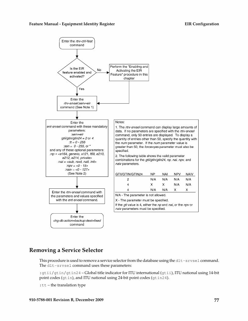
Removing a Service Selector
This procedure is used to remove a service selector from the database using the dlt-srvsel command.The dlt-srvsel command uses these parameters:
:gtii/gtin/gtin24 – Global title indicator for ITU international (gtii), ITU national using 14-bitpoint codes (gtin), and ITU national using 24-bit point codes (gtin24).
:tt – the translation type
77910-5788-001 Revision B, December 2009
EIR ConfigurationFeature Manual - Equipment Identity Register

:ssn – the subsystem number
:nai – Nature of address indicator (see Table 17: NAIV/NAI Mapping)
:naiv – Nature of address indicator value (see Table 17: NAIV/NAI Mapping )
Note:
The nature of address indicator parameters (naiv or nai) can be specified by supplying either amnemonic or an explicit value. At no time may both the mnemonic and the explicit value be specifiedat the same time for the same parameter. You can specify either the naiv or nai parameter. Table 17:NAIV/NAI Mapping shows the mapping between the naiv and the nai parameters.
Table 17: NAIV/NAI Mapping
DescriptionNAINAIV
Unknown–0
Subscriber NumberSub1
Reserved for national useRsvd2
National significant numberNatl3
International numberIntl4
Spare–
:np – Numbering plan (see Table 18: NPV/NP Mapping)
:npv – Numbering plan value (see Table 18: NPV/NP Mapping)
Note:
The numbering plan parameters (npv or np) can be specified by supplying either a mnemonic or anexplicit value. At no time may both the mnemonic and the explicit value be specified at the same timefor the same parameter. You can specify either the npv or np parameter. Table 18: NPV/NP Mappingshows the mapping between the npv and the np parameters.
Table 18: NPV/NP Mapping
DescriptionNPNPV
Unknown–0
ISDN/telephony numbering planE1641
Generic numbering planGeneric2
78910-5788-001 Revision B, December 2009
EIR ConfigurationFeature Manual - Equipment Identity Register
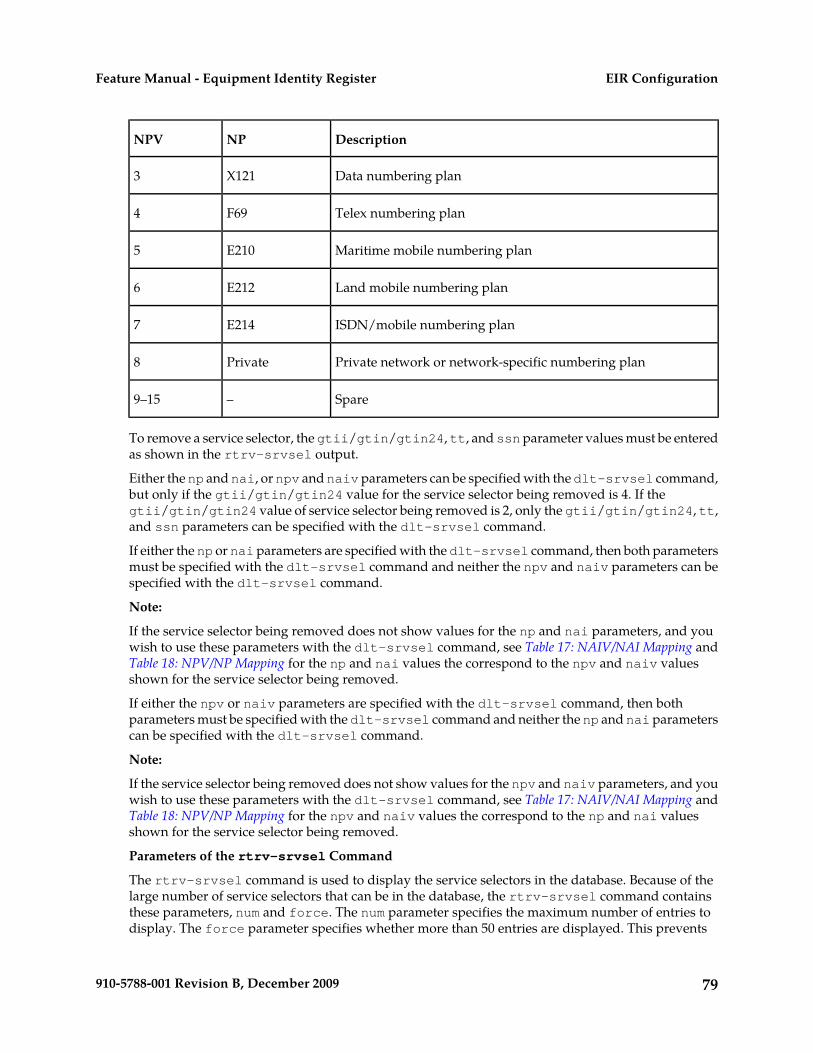
DescriptionNPNPV
Data numbering planX1213
Telex numbering planF694
Maritime mobile numbering planE2105
Land mobile numbering planE2126
ISDN/mobile numbering planE2147
Private network or network-specific numbering planPrivate8
Spare–9–15
To remove a service selector, the gtii/gtin/gtin24, tt, and ssn parameter values must be enteredas shown in the rtrv-srvsel output.
Either the np and nai, or npv and naiv parameters can be specified with the dlt-srvsel command,but only if the gtii/gtin/gtin24 value for the service selector being removed is 4. If thegtii/gtin/gtin24 value of service selector being removed is 2, only the gtii/gtin/gtin24, tt,and ssn parameters can be specified with the dlt-srvsel command.
If either the np or nai parameters are specified with the dlt-srvsel command, then both parametersmust be specified with the dlt-srvsel command and neither the npv and naiv parameters can bespecified with the dlt-srvsel command.
Note:
If the service selector being removed does not show values for the np and nai parameters, and youwish to use these parameters with the dlt-srvsel command, see Table 17: NAIV/NAI Mapping andTable 18: NPV/NP Mapping for the np and nai values the correspond to the npv and naiv valuesshown for the service selector being removed.
If either the npv or naiv parameters are specified with the dlt-srvsel command, then bothparameters must be specified with the dlt-srvsel command and neither the np and nai parameterscan be specified with the dlt-srvsel command.
Note:
If the service selector being removed does not show values for the npv and naiv parameters, and youwish to use these parameters with the dlt-srvsel command, see Table 17: NAIV/NAI Mapping andTable 18: NPV/NP Mapping for the npv and naiv values the correspond to the np and nai valuesshown for the service selector being removed.
Parameters of the rtrv-srvsel Command
The rtrv-srvsel command is used to display the service selectors in the database. Because of thelarge number of service selectors that can be in the database, the rtrv-srvsel command containsthese parameters, num and force. The num parameter specifies the maximum number of entries todisplay. The force parameter specifies whether more than 50 entries are displayed. This prevents
79910-5788-001 Revision B, December 2009
EIR ConfigurationFeature Manual - Equipment Identity Register

trying to display extremely large amounts of entries which could take hours. The rtrv-srvselcommand has 10 other parameters, gti/gtia/gtii/gtin/gtin24, tt, np, nai, npv, naiv, ssn,snp, snai, and serv.
• gti/gtia/gtii/gtin/gtin24 – the GTI value assigned to the service selector.• tt – the translation type assigned to the service selector.• np – the NP value assigned to the service selector.• nai – the NAI value assigned to the service selector.• npv – the NPV value assigned to the service selector.• naiv – the NAIV value assigned to the service selector.• ssn – the subsystem number assigned to the service selector.• snp – the SNP value assigned to the service selector.• snai – the SNAI value assigned to the service selector.• serv – the DSM service assigned to the service selector.
These parameters can also be used to limit the amount of information displayed with the rtrv-srvselcommand.
Note:
The snp and snai parameters are not used with EIR service selectors.
1. Display the service selectors in the database using the rtrv-srvsel command.
This is an example of the possible output:
rlghncxa03w 03-06-28 14:42:38 GMT Rel 35.0.0
GTII TT NP NAI NPV NAIV SSN SNP SNAI SERV4 1 e214 intl --- --- 3 --- --- eir4 1 e214 intl --- --- 4 e164 intl gport4 1 e214 intl --- --- 5 e164 intl smsmr4 2 e214 intl --- --- 5 e164 intl mnpsms4 2 e214 intl --- --- * --- --- eir
GTIN TT NP NAI NPV NAIV SSN SNP SNAI SERV2 75 --- --- --- --- 57 --- --- eir4 4 e214 natl --- --- --- e164 intl gflex4 9 e214 natl --- --- --- e164 intl gflex4 35 e214 natl --- --- 100 --- --- eir
SRV SELECTOR table is (9 of 20992) 1 % full
2. Remove the service selector from the database using the dlt-srvsel command.
For this example, enter these commands:
dlt-srvsel:serv=eir:tt=35:ssn=100:gtin=4:np=e214:nai=natl
dlt-srvsel:serv=eir:tt=57:ssn=75:gtin=2
When these commands have successfully completed, this message should appear:
rlghncxa03w 03-06-28 14:42:38 GMT Rel 35.0.0Service Selector table is (7 of 20992) 1% fullDLT-SRVSEL: MASP A - COMPLTD
80910-5788-001 Revision B, December 2009
EIR ConfigurationFeature Manual - Equipment Identity Register

3. Verify the changes with the rtrv-srvsel command with the parameters and values used in Step2.
For this example, enter these commands:
rtrv-srvsel:serv=eir:tt=35:ssn=100:gtin=4:np=e214:nai=intl
This is an example of the possible output.
rlghncxa03w 03-06-28 14:42:38 GMT Rel 35.0.0
GTIN TT NP NAI NPV NAIV SSN SNP SNAI SERVNo SRV Selector found in range
rtrv-srvsel:serv=eir:tt=57:ssn=75:gtin=2
This is an example of the possible output:
rlghncxa03w 03-06-28 14:42:38 GMT Rel 35.0.0
GTIN TT NP NAI NPV NAIV SSN SNP SNAI SERVNo SRV Selector found in range
4. Backup the new changes using the chg-db:action=backup:dest=fixed command.
The following messages should appear, the active Maintenance and Administration SubsystemProcessor (MASP) appears first:
BACKUP (FIXED): MASP A - Backup starts on active MASP.BACKUP (FIXED): MASP A - Backup on active MASP to fixed disk complete.BACKUP (FIXED): MASP A - Backup starts on standby MASP.BACKUP (FIXED): MASP A - Backup on standby MASP to fixed disk complete.
Figure 12: Removing a Service Selector
81910-5788-001 Revision B, December 2009
EIR ConfigurationFeature Manual - Equipment Identity Register

Changing an Existing Non-EIR Service Selector to an EIR Service Selector
This procedure is used to change a non-EIR service selector to an EIR service selector for the EIRfeature using the chg-srvsel command.
These are the only parameters that can be changed using this procedure:
:nserv – the new Service Module card service type, EIR
Note:
The nserv parameter contains other values. These values cannot be used in this procedure. The nservparameter can be used only if the current serv parameter value is not eir.
:nsnp – An EIR service selector cannot contain an SNP value, so if the service selector being changedcontains an SNP value, this value must be changed to none with this parameter.
82910-5788-001 Revision B, December 2009
EIR ConfigurationFeature Manual - Equipment Identity Register

:nsnai – An EIR service selector cannot contain an SNAI value, so if the service selector being changedcontains an SNAI value, this value must be changed to none with this parameter.
The chg-srvsel command requires that these parameters be specified with the values shown in thertrv-srvsel output for the service selector being changed. If you wish to change any of theseparameter values for an EIR service selector, remove the existing service selector using the Removinga Service Selector procedure, then add the new EIR service selector with the new parameter informationusing the Adding an EIR Service Selector procedure.
:gtii/gtin/gtin24 – Global title indicator for ITU international (gtii), ITU national using 14-bitpoint codes (gtin), and ITU national using 24-bit point codes (gtin24).
:tt – the translation type
:ssn – the subsystem number
:nai – Nature of address indicator (see Table 19: NAIV/NAI Mapping)
:naiv – Nature of address indicator value (see Table 20: NPV/NP Mapping)
Note:
The nature of address indicator parameters (naiv or nai) can be specified by supplying either amnemonic or an explicit value. At no time may both the mnemonic and the explicit value be specifiedat the same time for the same parameter. You can specify either the naiv or nai parameter. Table 19:NAIV/NAI Mapping shows the mapping between the naiv and the nai parameters.
Table 19: NAIV/NAI Mapping
DescriptionNAINAIV
Unknown–0
Subscriber NumberSub1
Reserved for national useRsvd2
National significant numberNatl3
International numberIntl4
Spare–5–127
:np – Numbering plan (see Table 20: NPV/NP Mapping)
:npv – Numbering plan value (see Table 20: NPV/NP Mapping)
Note:
The numbering plan parameters (npv or np) can be specified by supplying either a mnemonic or anexplicit value. At no time may both the mnemonic and the explicit value be specified at the same timefor the same parameter. You can specify either the npv or np parameter. Table 20: NPV/NP Mappingshows the mapping between the npv and the np parameters.
83910-5788-001 Revision B, December 2009
EIR ConfigurationFeature Manual - Equipment Identity Register

Table 20: NPV/NP Mapping
DescriptionNPNPV
Unknown–0
ISDN/telephony numbering planE1641
Generic numbering planGeneric2
Data numbering planX1213
Telex numbering planF694
Maritime mobile numbering planE2105
Land mobile numbering planE2126
ISDN/mobile numbering planE2147
Private network or network-specific numbering planPrivate8
Spare–9–15
Parameters of the rtrv-srvsel Command
The rtrv-srvsel command is used to display the service selectors in the database. Because of thelarge number of service selectors that can be in the database, the rtrv-srvsel command containsthese parameters, num and force. The num parameter specifies the maximum number of entries todisplay. The force parameter specifies whether more than 50 entries are displayed. This preventstrying to display extremely large amounts of entries which could take hours. The rtrv-srvselcommand has 10 other parameters, gti/gtia/gtii/gtin/gtin24, tt, np, nai, npv, naiv, ssn,snp, snai, and serv.
• gti/gtia/gtii/gtin/gtin24 – the GTI value assigned to the service selector.• tt – the translation type assigned to the service selector.• np – the NP value assigned to the service selector.• nai – the NAI value assigned to the service selector.• npv – the NPV value assigned to the service selector.• naiv – the NAIV value assigned to the service selector.• ssn – the subsystem number assigned to the service selector.• snp – the SNP value assigned to the service selector.• snai – the SNAI value assigned to the service selector.• serv – the DSM service assigned to the service selector.
84910-5788-001 Revision B, December 2009
EIR ConfigurationFeature Manual - Equipment Identity Register

These parameters can also be used to limit the amount of information displayed with the rtrv-srvselcommand.
Note:
The snp and snai parameters are not used with EIR service selectors.
1. Display the service selectors in the database using the rtrv-srvsel command.
This is an example of the possible output:
rlghncxa03w 03-06-28 14:42:38 GMT Rel 35.0.0GTII TT NP NAI NPV NAIV SSN SNP SNAI SERV4 1 e214 intl --- --- 3 --- --- eir4 1 e214 intl --- --- 4 e164 intl gport4 1 e214 intl --- --- 5 e164 intl smsmr4 2 e214 intl --- --- 5 e164 intl mnpsms4 2 e214 intl --- --- * --- --- eir
GTIN TT NP NAI NPV NAIV SSN SNP SNAI SERV2 75 --- --- --- --- 57 --- --- eir4 4 e214 natl --- --- 34 e164 intl gflex4 9 e214 natl --- --- 250 e164 intl gflex4 35 e214 natl --- --- 100 --- --- eir
SRV SELECTOR table is (9 of 20992) 1 % full
Note:
If the rtrv=srvsel output in Step 1 shows EIR service selectors, skip Step 2 and go to Step 3.
2. Verify that the EIR feature is enabled and activated by entering the rtrv-ctrl-feat command.If the EIR feature is enabled and activated, the status of the EIR feature is on. This is an exampleof the possible output:
rlghncxa03w 03-06-30 21:15:37 GMT Rel 35.0.0The following features have been permanently enabled:Feature Name Partnum Status QuantityTPS 893000110 on 1000ISUP Normalization 893000201 on ----Command Class Management 893005801 off ----Intermed GTT Load Sharing 893006901 off ----XGTT Table Expansion 893006101 off ----XMAP Table Expansion 893007710 on 3000Large System # Links 893005910 on 2000Routesets 893006401 on 6000
The following features have been temporarily enabled:Feature Name Partnum Status Quantity Trial Period LeftTPS 893000140 on 4000 20 days 8 hrs 57 mins
The following features have expired temporary keys:Feature Name Part NumZero entries found.
If the EIR feature is not enabled or activated, perform the Enabling and Turning On the EIR Featureprocedure to enable and activate the EIR feature before going to Step 3. If the EIR feature is enabledand activated, go to Step 3.
3. Change the service selector using the chg-srvsel command.For this example, enter this command:
85910-5788-001 Revision B, December 2009
EIR ConfigurationFeature Manual - Equipment Identity Register

chg-srvsel:gtin=4:tt=4:np=e214:nai=natl:ssn=34:nsnp=none:nsnai=none:nserv=eir
Note:
1. If the SNP, or SNAI parameter values are shown as dashes in the rtrv-srvsel output, theseparameters cannot be specified with the chg-srvsel command. If the gtii/gtin/gtin24parameter value is 2, the np, nai, npv, and naiv parameters cannot be specified with thechg-srvsel command.
2. If the gtii/gtin/gtin24 parameter value is 4, either the np and nai, or the npv and naivparameters must be specified with the chg-srvsel command. The np and nai parameterscan be specified in place of the npv and naiv parameters, and the npv and naiv parameterscan be specified in place of the np and naiv parameters so long as parameter values be specifiedcorrespond to the values shown in the rtrv-srvsel output. See Table 19: NAIV/NAI Mappingand Table 20: NPV/NP Mapping for more information on using these parameters.
3. The gtii/gtin/gtin24, tt, ssn, np, nai, npv, or naiv parameters cannot be changed inthis procedure. To change these parameters, remove the service selector using the Removing aService Selector procedure, then re-enter the service selector as an EIR service selector using theAdding an EIR Service Selector procedure.
When this command has successfully completed, this message should appear:
rlghncxa03w 03-06-28 14:42:38 GMT Rel 35.0.0 Service Selector table is (9 of 20992) 1% fullCHG-SRVSEL: MASP A - COMPLTD
4. Verify the changes with the rtrv-srvsel command with the serv=eir, gtii/gtin/gtin24,tt, ssn, np, nai, npv, and naiv parameters and values, as applicable, used in Step 3.
For this example, enter these commands:
rtrv-srvsel:gtin=4:tt=4:np=e214:nai=natl:ssn=34:serv=eir
This is an example of the possible output:
rlghncxa03w 03-06-28 14:42:38 GMT Rel 35.0.0
GTIN TT NP NAI NPV NAIV SSN SNP SNAI SERV4 4 e214 natl --- --- 34 --- --- eir
SRV SELECTOR table is (9 of 20992) 1 % full
5. Backup the new changes using the chg-db:action=backup:dest=fixed command.
The following messages should appear; the active Maintenance and Administration SubsystemProcessor (MASP) appears first:
BACKUP (FIXED): MASP A - Backup starts on active MASP.BACKUP (FIXED): MASP A - Backup on active MASP to fixed disk complete.BACKUP (FIXED): MASP A - Backup starts on standby MASP.BACKUP (FIXED): MASP A - Backup on standby MASP to fixed disk complete.
Figure 13: Changing an Existing Non-EIR Service Selector to an EIR Service Selector
86910-5788-001 Revision B, December 2009
EIR ConfigurationFeature Manual - Equipment Identity Register

87910-5788-001 Revision B, December 2009
EIR ConfigurationFeature Manual - Equipment Identity Register

Changing the EIR Options
This procedure is used to change the EIR Global Response status, EIR Response Type, and EIRIMSI Check status settings with the chg-gsmopts command. The chg-gsmopts command usesthese parameters to detect circular routing in the system:
:eirgrsp – The EIR Global Response type. The values for this parameter are:
• off – The EIR global response type is turned off.• whitelst – The White List EIR global response type is turned on.• graylst – The Gray List EIR global response type is turned on.• blklst – The Black List EIR global response type is turned on.• unknown – The Unknown EIR global response type is turned on.
The default value for this parameter is off.
When this parameter is set to off, the normal list logic is applied to the IMEI.
88910-5788-001 Revision B, December 2009
EIR ConfigurationFeature Manual - Equipment Identity Register

If the Global Response Type parameter is set to something other than off, no list logic processingoccurs and the response is sent to the MSC is either White List, Gray List, Black List, or Unknown,regardless of the actual status of the IMEI.
:eirrsptype – The EIR Response Type. This parameter determines how the lists are to be searched.The EIR Response Types are type1, type2, and type3.
For EIR Response Types 1 or 2, the IMEI searches are handled in this manner:
• If the IMEI is found in the Black List table, the search stops without searching the White and GrayList tables. The IMEI is considered Black Listed regardless of IMEI’s presence on the White or GrayList tables.
• If the IMEI is found in the Gray List table, but not found in the Black List table, the search stopswithout searching the White List table. The IMEI is considered Gray Listed regardless of the IMEI’spresence on the White List table.
For EIR Response Type 3, the IMEI searches are handled in this manner:
• The White List table is searched first. If the IMEI is not found in the White List table, the IMEI istreated as unknown - no other table searches need to be performed.
• If the IMEI is found in the White List table, the Black List table is searched next. If the IMEI is inthe White and Black List tables, the IMEI is considered Black Listed - no need to search the GrayList table.
• If the IMEI is found in White List table, but not in the Black List table, the Gray List table is searched.If the IMEI is in the White and Gray list tables, the IMEI is considered Gray Listed. If the IMEI isin the White List table, but not in the Gray List table, the IMEI is considered White Listed.
:eirimsichk – EIR IMSI Check status, off or on. This parameter indicates whether or not theIMSI is used when determining if an IMEI is to be Black Listed. If the eirimsichk parameter valueis on and an IMEI is found on the Black List, then the corresponding IMSI is retrieved. If the IMSIfound in the message matches the IMSI retrieved, then the IMEI is considered to be on the White List.If the IMSI's do not match or is not found, then the IMEI will remain Black Listed.
The EIR feature must be enabled and activated. Verify this by entering the rtrv-ctrl-featcommand. If the EIR feature is enabled and activated, the status of the EIR feature should be on. Ifthe EIR feature is not enabled and activated, perform the Enabling and Turning On the EIR Featureprocedure.
1. Display the status of the EIR options with the rtrv-gsmopts command.
This is an example of the possible output:
tekelecstp 08-09-08 14:53:59 EST EAGLE5 39.2.0 GSM OPTIONS ----------------------- DEFMCC = NONE DEFMNC = NONE SRFADDR = NONE MSRNDIG = RN IS412GSM = NONE DEFMAPVR = 1 EIRGRSP = BLKLST EIRRSPTYPE = TYPE2 EIRIMSICHK = ON SRIDNNOTFOUND = GTT
89910-5788-001 Revision B, December 2009
EIR ConfigurationFeature Manual - Equipment Identity Register

;
Note:
The rtrv-gsmopts command output contains other fields that are not used by this procedure. Ifyou wish to see all the fields displayed by the rtrv-gsmopts command, see the rtrv-gsmoptscommand description in the Commands Manual.
If the EIR options are not shown in the rtrv-gsmopts output, the EIR feature is not enabled andactivated. Perform the Enabling and Turning On the EIR Feature procedure, to enable and activatethe EIR feature.
2. Change the EIR options by entering the chg-gsmopts command with at least one of the EIR optionparameters.
For this example, enter thiscommand.chg-gsmopts:eirgrsp=whitelst:eirrsptype=type3:eirimsichk=offWhenthis command has successfully completed, this message should appear:
rlghncxa03w 03-06-07 00:22:57 GMT Rel 35.0.0CHG-GSMOPTS: MASP A - COMPLTD
3. Verify the changes using the rtrv-gsmopts command.
This is an example of the possible output:
tekelecstp 08-09-08 14:53:59 EST EAGLE5 39.2.0 GSM OPTIONS ----------------------- DEFMCC = NONE DEFMNC = NONE SRFADDR = NONE MSRNDIG = RN IS412GSM = NONE DEFMAPVR = 1 EIRGRSP = BLKLST EIRRSPTYPE = TYPE2 EIRIMSICHK = ON SRIDNNOTFOUND = GTT;
Note:
The rtrv-gsmopts command output contains other fields that are not used by this procedure. Ifyou wish to see all the fields displayed by the rtrv-gsmopts command, see the rtrv-gsmoptscommand description in the Commands Manual.
4. Back up the new changes using the chg-db:action=backup:dest=fixed command.
These messages should appear; the active Maintenance and Administration Subsystem Processor(MASP) appears first:
BACKUP (FIXED) : MASP A - Backup starts on active MASP.BACKUP (FIXED) : MASP A - Backup on active MASP to fixed disk complete.BACKUP (FIXED) : MASP A - Backup starts on standby MASP.BACKUP (FIXED) : MASP A - Backup on standby MASP to fixed disk complete.
Figure 14: Changing the EIR Options
90910-5788-001 Revision B, December 2009
EIR ConfigurationFeature Manual - Equipment Identity Register

The 1100 TPS/Service Module Card for ITU NP Feature
This procedure is used to enable and turn on the 1100 TPS/Service Module card for ITU NP feature.This feature provides up to 26,400 transactions per second when the maximum number of ServiceModule cards are installed in the EAGLE 5 ISS and one or more EPAP-related features (such as G-Port,G-Flex, A-Port, INP, EIR, Migration) are enabled and turned on.
This feature can be enabled only for Service Module cards that are rated at 850 transactions per second(TPS).
CAUTION: The increase of the Service Module card capacity, 1100 TPS per Service Modulecard, assumes incoming traffic consists of at least 30% of GTT routed traffic that does notrequire EPAP based lookup. If more than 70% of incoming traffic requires EPAP basedlookup, Group Ticket Voucher (TVG) may shutdown and overall TVG capacity of 1100for the card may not be met.
The feature access key is based on the feature’s part number and the serial number of the EAGLE 5ISS, making the feature access key site-specific.
91910-5788-001 Revision B, December 2009
EIR ConfigurationFeature Manual - Equipment Identity Register

The enable-ctrl-feat command enables the 1100 TPS/Service Module card for ITU NP featureby inputting the feature’s access key and the feature’s part number with these parameters:
:fakThe feature access key provided by Tekelec. The feature access key contains 13alphanumeric characters and is not case sensitive.
:partnumThe Tekelec-issued part number of the 1100 TPS/Service Module card for ITU NPfeature, 893018001.
After the 1100 TPS/Service Module card for ITU NP feature has been enabled, the feature must beturned on with the chg-ctrl-feat command. The chg-ctrl-feat command uses these parameters::partnum
The Tekelec-issued part number of the 1100 TPS/Service Module card for ITU NPfeature, 893018001.
:status=onUsed to turn the 1100 TPS/Service Module card for ITU NP feature on.
Activating the 1100 TPS/DSM for ITU NP FeatureThis procedure is used to enable and turn on the 1100 TPS/DSM for ITU NP feature.
The 1100 TPS/DSM for ITU NP feature increases the processing capacity of SCCP traffic for an EAGLE5 ISS processing EPAP-based traffic to 26,400 transactions per second. To provide this increase in SCCPprocessing capacity, the maximum of 25 Service Module cards must be provisioned and installed inthe EAGLE 5 ISS, and one or more EPAP-related features enabled and turned on. This feature can beenabled only for Service Module cards that are rated at 850 transactions per second (TPS).
Note: The increased capacity to 1100 TPS per Service Module card assumes incoming traffic consistsof at least 30% of GTT routed traffic that does not require EPAP-based lookup. If more than 70% ofincoming traffic requires EPAP-based lookup, Group Ticket Voucher (TVG) may shutdown and overallTVG capacity of 1100 for the card may not be met.
The 1100 TPS/DSM for ITU NP feature cannot be enabled if:
• The EAGLE 5 ISS does not contain any Service Module cards.• The LNP feature is enabled.• The ANSI G-Flex STP Option is enabled.• The GTT feature is not turned on.
The feature access key for the 1100 TPS/DSM for ITU NP feature is provided by Tekelec. Contact yourTekelec Sales Representative or Account Representative before beginning the feature activationprocedure if you do not have the feature access key for this feature. Based on the feature part numberand the serial number of the EAGLE 5 ISS, the feature access key is site-specific. The feature accesskey contains thirteen alphanumeric characters and is not case sensitive. The 1100 TPS/DSM for ITUNP feature cannot be enabled with a temporary feature access key.
The enable-ctrl-feat command requires that the database contain a valid serial number for theEAGLE 5 ISS, and that this serial number is locked. Verify with the rtrv-serial-num command.The EAGLE 5 ISS is shipped with a serial number in the database, but the serial number is not locked.The serial number can be changed, if necessary, and locked after the EAGLE 5 ISS is on-site with theent-serial-num command.
92910-5788-001 Revision B, December 2009
EIR ConfigurationFeature Manual - Equipment Identity Register

Note: To enter and lock the serial number of the EAGLE 5 ISS, the ent-serial-num command mustbe entered twice. The first entry of the ent-serial-num command adds the correct serial numberto the database with the serial parameter. The second entry of the ent-serial-num commandwith the serial and lock=yes parameters locks the serial number. Verify that the serial number inthe database is correct before locking the serial number. The serial number is on a label attached tothe control shelf (shelf 1100).
Refer to Commands Manual for detailed descriptions of all commands used in this procedure.
1. Display the status of the 1100 TPS/DSM for ITU NP feature by entering the rtrv-ctrl-featcommand.
Example of a possible output:rlghncxa03w 09-08-24 21:15:37 EST EAGLE 40.1.0
The following features have been permanently enabled:Feature Name Partnum Status QuantityHC-MIM SLK Capacity 893012707 on 64Prepaid SMS Intercept Ph1 893006701 on ----1100 TPS/DSM for ITU NP 893018001 on ----
The following features have been temporarily enabled:Feature Name Partnum Status Quantity Trial Period LeftMNP Circ Route Prevent 893000140 On ---- 20 days 8 hrs 57 mins
The following features have expired temporary keys:Feature Name Part NumOnOffFeatV
2. Based on the output in Step 1, perform one of the following:
• If the rtrv-ctrl-feat output shows that the LNP feature is enabled, this procedure cannotbe performed. The 1100 TPS/DSM for ITU NP feature cannot be enabled if the LNP feature isenabled.
• If the 1100 TPS/DSM for ITU NP entry of the rtrv-ctrl-feat output shows that the 1100TPS/DSM for ITU NP feature is enabled and the feature status is on, no further action isnecessary.
• If the feature is enabled and the feature status is off, go to Step 13.• If the 1100 TPS/DSM for ITU NP and LNP features are not enabled, continue to Step 3.
3. Determine whether the G-Flex feature is turned on by entering the rtrv-ctrl-feat .
The status of the G-Flex feature is shown by the G-Flex entry in the rtrv-ctrl-feat output.
• If the G-Flex feature is on, continue to Step 4.• If the G-Flex feature is off, go to Step 5.
4. Verify that the ANSI G-Flex option is not enabled or turned on by entering the rtrv-stpoptscommand.
The 1100 TPS/DSM ITU NP feature cannot be enabled if the ANSI G-Flex option is turned on.
The ANSI G-Flex option is shown by the ANSIGFLEX entry in the rtrv-stpopts output. If theANSIGFLEX entry is displayed in the rtrv-stpopts output, both the G-Flex and the GTT featuresare turned on.
93910-5788-001 Revision B, December 2009
EIR ConfigurationFeature Manual - Equipment Identity Register

• If the ANSIGFLEX value is yes in the rtrv-stpopts output , the ANSI G-Flex option is enabledand the remainder of this procedure cannot be performed.
• If the ANSIGFLEX value is no in the rtrv-stpopts output, the ANSI G-Flex option is notenabled. Proceed to Step 6.
5. Determine whether the GTT feature is turned on by examining the output of the rtrv-featcommand.
The 1100 TPS/DSM ITU NP feature cannot be enabled unless the GTT feature is turned on. TheGTT feature is shown by the GTT entry in the rtrv-feat output in Step 3.
• If the GTT feature is turned on, continue to Step 6.• If the GTT feature is turned off, perform ”Adding a Service Module” in Database Administration
Manual - Global Title Translation to turn on the GTT feature and to add the required number ofService Module cards to the database. After ”Adding a Service Module” has been performed,go to Step 11.
6. Verify the number of Service Module cards provisioned in the database using thertrv-card:appl=vsccp command:
Example of a possible output:tklc1110501 07-04-12 17:28:02 EST EAGLE5 37.0.0CARD VERSION TYPE GPL PST SST AST1111 128-015-000 DSM SCCPHC IS-NR Active -----1101 128-015-000 DSM VSCCP IS-NR Active -----
Command Completed.
7. Based on the output shown in Step 6, perform one of the following:
• If the required number of Service Module cards is provisioned in the database, continue to Step8.
• If the required number of Service Module cards is not provisioned in the database, perform”Adding a Service Module” in Database Administration Manual - Global Title Translation to addthe required number of Service Module cards to the database. After ”Adding a Service Module”has been performed, continue with Step 8.
8. Display the serial number in the database with the rtrv-serial-num command.
Example of a possible output:rlghncxa03w 09-08-24 21:15:37 EST EAGLE 40.1.0
System serial number = nt00000123
System serial number is not locked. rlghncxa03w 09-08-24 21:15:37 EST EAGLE 40.1.0Command Completed
9. Compare the serial number located on a label affixed to the control shelf (shelf 1100) to the outputshown in Step 8, then perform one of the following:
• If the serial number is not correct and is locked, this feature cannot be enabled and the remainderof this procedure cannot be performed. Contact Customer Care Center to change an incorrect andlocked serial number.
• If the serial number is not correct and is not locked, continue to Step 10.
94910-5788-001 Revision B, December 2009
EIR ConfigurationFeature Manual - Equipment Identity Register

• If the serial number is correct but is not locked, go to Step 12.• If the serial number is correct and is locked, go to Step 13.
10. Enter the correct serial number into the database using the ent-serial-num command with theserial parameter.
Command example:
ent-serial-num:serial=<EAGLE 5 ISS serial number>
After the command has completed successfully, this message is displayed:rlghncxa03w 09-08-24 21:15:37 EST EAGLE 40.1.0ENT-SERIAL-NUM: MASP A - COMPLTD
11. Verify with the rtrv-serial-num command that the serial number entered in Step 10 was enteredcorrectly. If the serial number was not entered correctly, repeat Step 10 and enter the correct serialnumber.
Example of a possible output:rlghncxa03w 09-08-24 21:15:37 EST EAGLE 40.1.0System serial number = nt00000123
System serial number is not locked.
rlghncxa03w 09-08-24 21:15:37 EST EAGLE 40.1.0Command Completed
12. Lock the serial number in the database by entering the ent-serial-num command with thecorrect serial number as shown in Step 11 and with the lock=yes parameter value.
Command example:
ent-serial-num:serial=<EAGLE 5 ISS serial number>:lock=yes
After the command has completed successfully, this message is displayed:rlghncxa03w 09-08-24 21:15:37 EST EAGLE 40.1.0ENT-SERIAL-NUM: MASP A - COMPLTD
13. Enable the 1100 TPS/DSM for ITU NP feature with the feature access key using theenable-ctrl-feat command.
Command example:
enable-ctrl-feat:partnum=893018001:fak=<feature access key>
Note: The feature access key for the 1100 TPS/DSM for ITU NP feature is provided by Tekelec.Contact your Tekelec Sales Representative or Account Representative if you do not have the featureaccess key for this feature. This feature cannot be enabled with a temporary feature access key.
After the command has completed successfully, this message is displayed:rlghncxa03w 09-08-24 21:15:37 EST EAGLE 40.1.0ENABLE-CTRL-FEAT: MASP B - COMPLTD
14. Perform on of the following:
• To turn on the 1100 TPS/DSM for ITU NP feature, go to Step 15.• To not turn on the 1100 TPS/DSM for ITU NP feature, go to Step 17. The transaction rate will
remain at 850 TPS per Service Module card.
95910-5788-001 Revision B, December 2009
EIR ConfigurationFeature Manual - Equipment Identity Register

15. To turn on the 1100 TPS/DSM for ITU NP feature, enter the chg-ctrl-feat command, specifyingthe 1100 TPS/DSM for ITU NP feature part number and the status=on parameter value.
Command example:
chg-ctrl-feat:partnum=893018001:status=on
This message is displayed:CAUTION: Rated TPS for this feature supports an engineered GTTtraffic mix of no more than 70 percent EPAP-based traffic.Re-enter the command within 30 seconds to confirm change.
CAUTION: If the EPAP-based traffic is higher than 70% of all traffic on the EAGLE5 ISS, the Service Module card performance may not reach 1100 TPS per Service Modulecard.
16. Re-enter the chg-ctrl-feat command to turn on the feature.
Command example:
chg-ctrl-feat:partnum=893018001:status=on
After the command has completed successfully, this message is displayed:rlghncxa03w 09-08-24 21:15:37 EST EAGLE 40.1.0 CHG-CTRL-FEAT: MASP B - COMPLTD
17. Verify the changes by entering the rtrv-ctrl-feat command with the 1100 TPS/DSM for ITUNP feature part number.
Command example:
rtrv-ctrl-feat:partnum=893018001
Example of a possible output:rlghncxa03w 09-08-24 21:15:37 EST EAGLE 40.1.0The following features have been permanently enabled: Feature Name Partnum Status Quantity 1100 TPS/DSM for ITU NP 893018001 on ----
The following features have been temporarily enabled: Feature Name Partnum Status Quantity Trial Period Left Zero entries found.
The following features have expired temporary keys: Feature Name Part Num Zero entries found.
18. Back up the new database changes with the chg-db command:
Command example:
chg-db:action=backup:dest=fixed
These messages are displayed. The active Maintenance and Administration Subsystem Processor(MASP) is displayed first.BACKUP (FIXED) : MASP A - Backup starts on active MASP. BACKUP (FIXED) : MASP A - Backup on active MASP to fixed disk complete. BACKUP (FIXED) : MASP A - Backup starts on standby MASP. BACKUP (FIXED) : MASP A - Backup on standby MASP to fixed disk complete.
96910-5788-001 Revision B, December 2009
EIR ConfigurationFeature Manual - Equipment Identity Register

To turn off the 1100 TPS/DSM for ITU NP feature, enter the chg-ctrl-feat command, specifyingthe 1100 TPS/DSM feature part number and the status=off parameter value.
chg-ctrl-feat:partnum=893018001:status=off
This message is displayed:CAUTION: This command decreases the total TPS of the SCCP system from 1100 to 850 TPS for each DSM card.
Confirm that you wish to turn off the 1100 TPS/DSM for ITU NP feature by re-entering the commandwithin 30 seconds.
chg-ctrl-feat:partnum=893018001:status=off
This message is displayed:rlghncxa03w 09-08-24 21:15:37 EST EAGLE 40.1.0CHG-CTRL-FEAT: MASP B - COMPLTD
Activating the E5-SM4G Throughput Capacity Feature
The E5-SM4G Throughput Capacity feature quantities are used to increase the processing capacity ofthe E5-SM4G card and of system SCCP traffic for an EAGLE 5 ISS that contains E5-SM4G cards. Theachievable TPS maximums are shown in Table 21: Maximum E5-SM4G Card and System TPS Capacity .
Table 21: Maximum E5-SM4G Card and System TPS Capacity
Maximum System TPS CapacityMaximumTPS Capacityper E5-SM4GCard
FeatureQuantity PartNumber
3125893019101• 75,000 TPS with one or more EPAP-related features and 24+1
cards
5000• 150,000 TPS with no EPAP-related or ELAP-related feature traffic
and 31+1 cards• 120,000 TPS with G-Flex and the ANSIGFLEX STP option and
24+1 cards• 40,000 TPS with ELAP and 8+1 cards
6800893019102• 210,800 TPS with 150,000 TPS with no EPAP-related or
ELAP-related feature traffic and 31+1 cards• 163,200 TPS with one or more EPAP-related features and 24+1
cards• 54,400 TPS with ELAP and 8+1 cards
An E5-SM4G Throughput Capacity quantity feature must be enabled using an E5-SM4G ThroughputCapacity feature part number (893019101 or 893019102) and a feature access key.
97910-5788-001 Revision B, December 2009
EIR ConfigurationFeature Manual - Equipment Identity Register

The feature access key is based on the feature part number and the serial number of the EAGLE 5 ISS,making the feature access key site-specific.
Note: The E5-SM4G Throughput Capacity quantity feature must be purchased to receive the featureaccess key used to enable the feature. Contact your Tekelec Sales Representative or AccountRepresentative before beginning this procedure if you have purchased the E5-SM4G ThroughputCapacity quantity feature, but do not have the feature access key. A temporary feature access key isnot available for this feature.
After an E5-SM4G Throughput Capacity feature is enabled and turned on, the E5-SM4G ThroughputCapacity feature cannot be turned off. When the E5-SM4G Throughput Capacity feature is enabled,it is permanently enabled. The E5-SM4G Throughput Capacity feature cannot be temporarily enabled.
System Prerequisites
Before any feature that is described in this manual can be enabled, the prerequisites listed in Table 22:System Prerequisites are required in the system.
Table 22: System Prerequisites
Verification and ProvisioningPrerequisite
Enter the rtrv-serial-num command todisplay the serial number and its lock status.
For new installations, the system serial numbermust be verified and locked. The system isshipped with an unlocked serial number. The Verify that the displayed serial number is correct
for the system. The serial number is shown on alabel affixed to the control shelf (shelf 1100).
serial number can be changed if necessary andmust be locked after the system is on-site.
For systems that are being upgraded, the serialnumber has already been verified and locked. If no serial number is displayed, or if the
displayed serial number is not locked, refer to theent-serial-number command description inthe Commands Manual for instructions to enter andlock the serial number.
Enter the rept-stat-card:appl=vsccpcommand to list the Service Module cards in thesystem.
Service Module cards (DSM cards, E5-SM4Gcards, or a mixture of both) must be equipped.
Some features require only E5-SM4G cards andcannot use DSM cards. See the specific featureprerequisites in this section.
Some features require only E5-SM4G cards andcannot use DSM cards. See the specific featureprerequisites in this section.
Note: Refer to the Dimensioning Guide for EPAPAdvanced DB Features Technical Reference forinformation on the dimensioning rules and thedatabase capacity requirements for EPAP-relatedfeatures.
Enter the rtrv-feat command.The GTT feature must on in the system.
98910-5788-001 Revision B, December 2009
EIR ConfigurationFeature Manual - Equipment Identity Register

Verification and ProvisioningPrerequisite
If the GTT feature is on, the gtt=on entry appearsin the output.
If the gtt=off entry appears in the output, use theprocedures in the Database Administration Manual– Global Title Translation to turn on the GTTfeature.
E5-SM4G Throughput Capacity Feature Prerequisite
Before the E5-SM4G Throughput Capacity feature can be enabled, the prerequisite shown in Table 23:E5-SM4G Throughput Capacity Feature Prerequisite is required in the system.
Table 23: E5-SM4G Throughput Capacity Feature Prerequisite
Verification and ProvisioningPrerequisite
Enter the rept-stat-gpl:gpl=sccphccommand to list the E5-SM4G cards in the system.
E5-SM4G cards running the VSCCP applicationmust be equipped.
The required number of cards depends on thedesired total system TPS to be achieved by the
If the number of cards is not sufficient, use theprocedure in Adding a Service Module Card to addE5-SM4G cards.cards. See Table 21: Maximum E5-SM4G Card and
System TPS Capacity .
The following procedure explains how to enable an E5-SM4G Throughput Capacity quantity feature.
Note: After a quantity feature has been enabled, a feature for a higher quantity can be enabled; afeature for a lower quantity cannot be enabled. Quantity features are automatically turned on whenthey are enabled.
1. Display the status of the features that are controlled by feature access keys. Enter thertrv-ctrl-feat command. rlghncxa03w 09-07-29 16:40:40 EST EAGLE5 41.1.0 The following features have been permanently enabled: Feature Name Partnum Status Quantity HC-MIM SLK Capacity 893012707 on 64 E5-SM4G Throughput Cap 893019101 on 3125;
• If the rtrv-ctrl-feat output shows that the correct E5-SM4G Throughput Capacity quantityfeature is enabled and its status is on, no further action is necessary.
• If no E5-SM4G Throughput Capacity feature quantity is enabled or a higher quantity needs tobe enabled, go to step Step 2.
2. Enable the E5-SM4G Throughput Capacity quantity feature by entering the enable-ctrl-featcommand.enable-ctrl-feat:partnum=8930109102:fak=<feature access key>
3. Verify the status of the E5-SM4G Throughput Capacity quantity feature by entering thertrv-ctrl-feat command with the feature part number that was just enabled (893033501 or893019102).
99910-5788-001 Revision B, December 2009
EIR ConfigurationFeature Manual - Equipment Identity Register
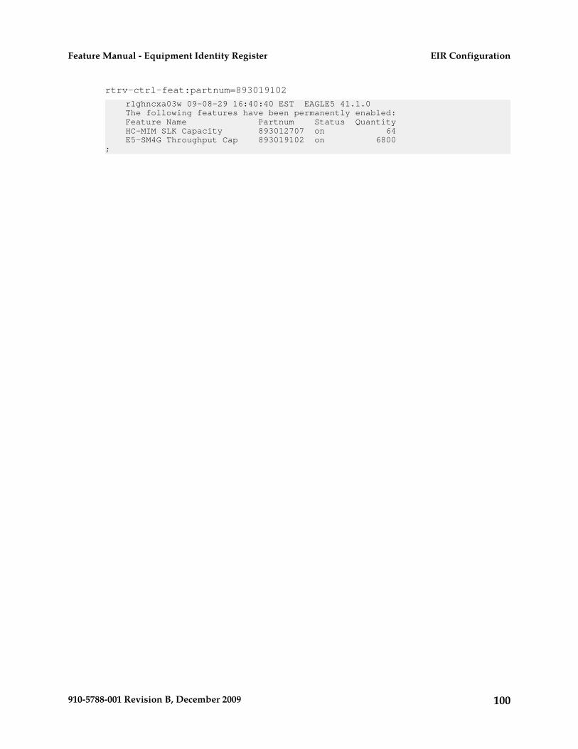
rtrv-ctrl-feat:partnum=893019102
rlghncxa03w 09-08-29 16:40:40 EST EAGLE5 41.1.0 The following features have been permanently enabled: Feature Name Partnum Status Quantity HC-MIM SLK Capacity 893012707 on 64 E5-SM4G Throughput Cap 893019102 on 6800;
100910-5788-001 Revision B, December 2009
EIR ConfigurationFeature Manual - Equipment Identity Register

Chapter
5Maintenance and Measurements
This chapter describes maintenance andmeasurements in detail, including EPAP status and
Topics:
• Hardware Requirements.....102 alarms, hardware verification messages, EIR system• EPAP Status and Alarms.....102 status reports and commands, code and application
data loading, and alarms.• EIR System Status Reports.....103• Code and Application Data Loading.....104• EIR Alarms.....110• EIR UIMs.....116• EIR Measurements.....120
101910-5788-001 Revision B, December 2009

Hardware Requirements
The EIR feature requires Service Module cards to run the VSCCP application. The EAGLE 5 ISS maybe equipped with from 1 to 25 Service Module cards to support EIR.
The EIR feature also requires a T1000 or a T1200 AS based MPS system.
EPAP Status and Alarms
Because EPAP has no direct means of accepting user input or displaying output messages on EAGLE5 ISS terminals, maintenance, measurements, and status information are routed through a ServiceModule card. EPAP sends two types of messages to the Service Module card: EPAP Maintenance Blocksand DSM Status Requests. Each message type is discussed in the following sections.
EPAP Maintenance Blocks
The active EPAP generates and sends maintenance blocks to the primary Service Module card. Onemaintenance block is sent as soon as the IP link is established between the active EPAP and the primaryService Module card. Additional maintenance blocks are sent whenever the EPAP needs to report anychange in status or error conditions. The information returned in maintenance blocks is included inthe output of the rept-stat-mps and rept-stat-sccp commands.
The EPAP sends maintenance blocks that contain at least the following information:
• Status of EPAP 'A' - actual states are active, standby, and down (inoperative). Maintenance blocksinclude a field for this information so that it can be forwarded to the EPAP A Device Control Block(DCB), where it is available for the output of the rept-stat-mps command.
• Status of EPAP 'B' - actual states are active, standby, and down (inoperative). Maintenance blocksinclude a field for this information so that it can be forwarded to the EPAP B DCB, where it isavailable for the output of the rept-stat-mps command.
• Identification of Active EPAP - a field to identify the active EPAP.• Congestion Indicator - an indicator showing provisioning link congestion. The link between the
EPAPs and the external source of provisioning data can become congested in high-provisioningtraffic situations. When this occurs and subsequently as the congestion clears, the EPAP sendsmaintenance blocks to the Service Module card. The EPAP must ensure that no more than onemaintenance block per second is sent to the primary Service Module card if the only reason is toreport a change in congestion status.
• Alarm Conditions - an error code field. If the EPAP needs to report an alarm condition, it puts anappropriate UAM identifier in this field.
• Current MPS Database Size - a field indicating the current RTDB size. The Service Module carduses this information to calculate the percentage of memory utilized by the RTDB.
DSM Status Requests
When the EPAP needs to know the status of a Service Module card, it sends a DSM status request tothat Service Module card. Because status messages are sent over UDP, the EPAP broadcasts the DSM
102910-5788-001 Revision B, December 2009
Maintenance and MeasurementsFeature Manual - Equipment Identity Register

status request (to all Service Module cards) and each Service Module card returns its status to theEPAP.
DSM Status Reporting to the EPAP
The sections that follow describe the DSM status reporting for the EPAP.
DSM Status Messages – When Sent
Service Module cards send a DSM status message to the EPAP when any the following events occurin the Service Module card:
• The Service Module card is booted.• The Service Module card receives a DSM Status Request message from the EPAP• The Service Module card determines that it needs to download the entire database, for example,
if the Service Module card determines that the RTDB needs to be downloaded (for instance, if thedatabase is totally corrupted), or if a craftsperson requests that the database be reloaded.
• The Service Module card starts receiving database downloads or database updates. When a ServiceModule card starts downloading the RTDB or accepting database updates, it sends a DSM StatusMessage informing the EPAP of the first record received. This helps the EPAP keep track ofdownloads in progress.
DSM Status Messages Fields
The DSM Status Message provides the following information to the EPAP:
• DSM Memory Size. When the Service Module card is initialized, it determines the amount ofmemory present. The EPAP uses the value to determine if the Service Module card has enoughmemory to hold the RTDB.
Refer to the Dimensioning Guide for EPAP Advanced DB Features Technical Reference for importantinformation on the dimensioning rules and the Service Module card database capacity requirements.
• Load Mode Status. This indicator indicates whether or not 80% of the IS-NR (In-Service Normal)LIMs have access to SCCP services.
EIR System Status Reports
Status reporting described here includes the following:
• System status• EIR status• Service Module card memory capacity status• Loading mode support status
System Status Reporting
The rept-stat-sys command supports the Service Module cards running the VSCCP application.
103910-5788-001 Revision B, December 2009
Maintenance and MeasurementsFeature Manual - Equipment Identity Register

The rept-stat-sccp command supports the Service Module cards running the VSCCP applicationand reports EIR statistics.
EIR Status Reporting
The rept-stat-mps command supports EIR system reporting. rept-stat-mps concentrates onreporting the status of the provisioning system. See "Maintenance and Measurements User InterfaceCommands", for more details. EIR statistics are placed in the rept-stat-sccp command.
Service Module card Memory Capacity Status Reporting
As described in the DSM Status Messages Fields, the Service Module card sends a message to the EPAPcontaining the amount of memory on the Service Module card. The EPAP determines whether theService Module card has enough memory to store the RTDB and sends an ack or nak back to theService Module card indicating whether or not the Service Module card has an adequate amount ofmemory. Refer to the Dimensioning Guide for EPAP Advanced DB Features Technical Reference for importantinformation on the dimensioning rules and the Service Module card database capacity requirements.
When the EPAP sends database updates to the Service Module cards, the update messages include afield that contains the new database memory requirements. Each Service Module card monitors theDB size requirements, and issues a minor alarm if the size of the DB exceeds 80% of its memory. If adatabase increases to the point that there is insufficient Service Module card memory, a major alarmis issued.
The rept-stat-mps:loc=xxxx command shows the amount of memory used by the RTDB as apercent of available Service Module card memory.
Loading Mode Support Status Reporting
The OAM application determines whether or not the system is in an unstable loading mode since itknows the state of all LIM, SCCP, and Service Module cards in the system. When the loading modeis unstable, the rept-stat-sys command reports the existence of the unstable loading mode andthe specific conditions that caused it. Refer to Loading Mode Support, for more details.
Code and Application Data Loading
In general, administrative updates can occur while a Service Module card is loading. The ServiceModule card should also remain in an in-transition state if the STP portion of the database has completedloading and is waiting for the RTDB to download.
Service Module Card Code Loading
The EAGLE 5 ISS OAM performs code loading of the Service Module card.
EPAP Application Data Loading
The EIR feature requires that new TDM-resident data tables be loaded in addition to those currentlysupported by EAGLE 5 ISS. The GPL and data loading support this additional table loading whilemaintaining support for loading the existing EAGLE 5 ISS tables.
104910-5788-001 Revision B, December 2009
Maintenance and MeasurementsFeature Manual - Equipment Identity Register

In order to support both RTDB and EAGLE 5 ISS data loading, the Service Module card GPL verifiesits hardware configuration during initialization to determine if it has the capacity to support the RTDB.
The Service Module card GPL application data loader registers all tables for loading, independent ofthe EIR feature provisioning and main board / applique hardware configuration. As a result, loadrequests are always identical. During loading, multiple Service Module card load requests are combinedinto a single download, reducing the overall download time. The Service Module card stores or discardsRTDB table data based on whether or not it has RTDB-capable hardware for features like G-Port,G-Flex, INP, and EIR.
The OAM, on the other hand, downloads or sets memory boundaries for the EIR options, HOMERN,and service selector tables only if the EIR feature is provisioned. When the EIR feature is not provisioned,the OAM does not attempt to read these tables from disk. Instead, empty tables (i.e., tables withoutentries) are downloaded. All other tables requested for loading are read from disk and downloadedroutinely.
Non EIR Data Initialization
If the Service Module card's hardware configuration cannot support the RTDB, the EIR tables aremarked as absent during Service Management System initialization. Memory is not reserved for theEIR table data. EIR tables are registered with the application data loader (ADL), specifying a datadiscard function. EIR table data is discarded during loading by the ADL discard function, rather thanstoring it in memory.
EPAP-Service Module Card Loading Interface
The Service Module card must convey to the EPAP that it needs to download the RTDB. This occurswhen the Service Module card sends a Full Download Request message to the EPAP.
Loading Mode Support
No more than 16 LIMs can be serviced by each Service Module card.
80% Threshold of Support
Loading mode is based on the ability of the system to provide SCCP service to at least 80% of the LIMs.
Service Module Card Capacity
An insufficient number of Service Module cards that are in the is-nr (In Service - Normal) oroos-mt-dsbld (Out of Service - Maintenance Disabled) relative to 80% of the number of provisionedLIMs is called a “failure to provide adequate SCCP capacity.”
Insufficient SCCP Service
It is also possible for LIMs or Service Module cards to be inhibited or to have problems that preventthem from operating normally. If enough Service Module cards are out of service, it may not be possiblefor the remaining is-nr Service Module cards to service at least 80% of the number of is-nr LIMs. Thisis called “insufficient SCCP service.” When this occurs, some of the LIMs are denied SCCP service. Itis possible to inhibit LIMs to bring the ratio back to 16:1 (or better).
105910-5788-001 Revision B, December 2009
Maintenance and MeasurementsFeature Manual - Equipment Identity Register

Conditions That Create an Unstable Loading Mode
The current system implementation interrupts and aborts card loading upon execution of an STPdatabase chg command. Loading mode support denies the execution of EAGLE 5 ISS database chgcommands when the system is in an unstable loading mode. An unstable loading mode exists whenany of the following conditions are true:
• The system's maintenance baseline has not been established.• Less than 80% of the number of LIMs provisioned are is-nr or oos-mt-dsbld.• The number of is-nr and oos-mt-dsbld Service Module cards running the VSCCP application is
insufficient to service at least 80% of all provisioned LIMs.• Insufficient SCCP service occurs when an insufficient number of is-nr Service Module cards are
available to service at least 80% of the number of is-nr LIMs.• LIM cards are being denied SCCP service and any Service Module cards are in an abnormal state
(oos-mt or is-anr).
Effects of System in an Unstable Loading Mode
• No affect on RTDB downloads or updates.
Unstable loading mode has no impact on RTDB downloads or the stream of RTDB updates.• rept-stat-sys reports unstable loading mode.
When the loading mode is unstable, the rept-stat-sys command response reports the existenceof the unstable loading mode and the specific trigger that caused it.
• No STP database updates allowed.
Once an STP database has been loaded, that database can be updated (as long as the system is notin an unstable loading mode). However, if an STP update arrives during STP database loading,the Service Module card aborts the current loading, issues a class 01D7 obit, and reboots. Figure15: Obit Message for Abort of Card Loading shows an example.Figure 15: Obit Message for Abort of Card Loading
106910-5788-001 Revision B, December 2009
Maintenance and MeasurementsFeature Manual - Equipment Identity Register

Using the force Option
Use the force option to force the execution of commands that would put the system in unstable loadingmode. If executing the ent-card or inh-card commands would cause the system to enter an unstableloading mode, use the force option on the command.
State Transitions During Start-Up
Figure 16: EPAP-related Feature Enabled, Normal Operating Sequence through Figure 22: EPAP-relatedFeature Activation Unsuccessful due to Insufficient Database show the transitions that a Service Modulecard goes through as it boots, loads code and data, and runs various VSCCP services. These figuresdo not illustrate every possible situation, but they do include the most common scenarios involvingEPAP-related features.
In Figure 16: EPAP-related Feature Enabled, Normal Operating Sequence, the EPAP-related feature isenabled, and the Service Module card memory is at least 1 GB and is connected to the EPAP. A normalService Module card operating sequence occurs, providing EPAP-related feature service.Figure 16: EPAP-related Feature Enabled, Normal Operating Sequence
107910-5788-001 Revision B, December 2009
Maintenance and MeasurementsFeature Manual - Equipment Identity Register

In Figure 17: EPAP-related Feature Enabled, but Service Module card Memory Less Than 1 GB, theEPAP-related feature is enabled, but the Service Module card memory is less than 1 GB. TheEPAP-related feature cannot begin operation. Refer to Dimensioning Guide for EPAP Advanced DBFeatures Technical Reference for important information about the dimensioning rules and the ServiceModule card database capacity requirements.Figure 17: EPAP-related Feature Enabled, but Service Module card Memory Less Than 1 GB
In Figure 18: EPAP-related Feature Enabled, but Service Module card Not Connected to EPAP, theEPAP-related feature is enabled, the Service Module card memory has at least 1 GB, but the ServiceModule card is unable to connect EPAP; the EPAP-related feature cannot begin operation.Figure 18: EPAP-related Feature Enabled, but Service Module card Not Connected to EPAP
In Figure 19: EPAP-related Feature Enabled, but Service Module card Memory Insufficient for Database , theEPAP-related feature is enabled, the Service Module card has the required 1 GB memory and isconnected to the EPAP, but the Service Module card is too small for the required database; theEPAP-related feature cannot begin operation. Refer to Dimensioning Guide for EPAP Advanced DBFeatures Technical Reference for important information about the dimensioning rules and the ServiceModule card database capacity requirements.Figure 19: EPAP-related Feature Enabled, but Service Module card Memory Insufficient for Database
108910-5788-001 Revision B, December 2009
Maintenance and MeasurementsFeature Manual - Equipment Identity Register

In Figure 20: EPAP-related Feature Enabled, but Database Exceeds Service Module card Memory, theEPAP-related feature is enabled, the Service Module card is connected to the EPAP, but the RTDBgrows eventually to exceed the capacity of the Service Module card memory, despite its memory sizeof at least 1 GB (an alarm is issued when the Service Module card memory becomes full from the RTDBupdate). The EPAP-related feature cannot begin operation. Refer to Dimensioning Guide for EPAPAdvanced DB Features Technical Reference for important information about the dimensioning rules andthe Service Module card database capacity requirements.Figure 20: EPAP-related Feature Enabled, but Database Exceeds Service Module card Memory
In Figure 21: EPAP-related Feature Not Enabled at First, but then Activated on Service Module card, theEPAP-related feature is not initially enabled; the Service Module card memory has at least 1 GB butno EPAP connection; the Service Module card is running other applications when the EPAP-relatedfeature is turned on; the Service Module card has sufficient memory to provide EPAP-related featureservice.Figure 21: EPAP-related Feature Not Enabled at First, but then Activated on Service Module card
In Figure 22: EPAP-related Feature Activation Unsuccessful due to Insufficient Database, the EPAP-relatedfeature is not initially enabled; the Service Module card memory has at least 1 GB but no EPAPconnection, and is running other applications when the EPAP-related feature is turned on. However,the Service Module card memory is insufficient for the needed database, and the cannot provide
109910-5788-001 Revision B, December 2009
Maintenance and MeasurementsFeature Manual - Equipment Identity Register

EPAP-related feature operation. Refer to the Dimensioning Guide for EPAP Advanced DB Features TechnicalReference for important information about the dimensioning rules and the Service Module card databasecapacity requirements.Figure 22: EPAP-related Feature Activation Unsuccessful due to Insufficient Database
EIR Alarms
All EIR related UAMs are output to the Maintenance Output Group. The Unsolicited Alarm andInformation Messages manual contains a complete description of all UAMs. Table 24: EIR UAMs containsa listing of UAMs used to support the EIR feature.
Refer to the EAGLE 5 ISS Maintenance Manual for more information and corrective procedures for theEAGLE 5 ISS related alarms. Refer to the MPS Platform Software and Maintenance Manual for moreinformation and corrective procedures for the MPS related alarms.
Table 24: EIR UAMs
MPS or EAGLE 5 ISSMessage TextSeverityUAM
EAGLE 5 ISSCard is isolated from systemMajor0013
EAGLE 5 ISSIP Connection UnavailableMajor0084
EAGLE 5 ISSIP Connection AvailableNone0085
EAGLE 5 ISSIncompatible HW for provisioned slotMajor0099
MPSMPS availableNone0250
MPSMPS unavailableCritical0261
MPSCritical Platform Failure(s)Critical0370
110910-5788-001 Revision B, December 2009
Maintenance and MeasurementsFeature Manual - Equipment Identity Register

MPS or EAGLE 5 ISSMessage TextSeverityUAM
MPSCritical Application Failure(s)Critical0371
MPSMajor Platform Failure(s)Major0372
MPSMajor Application Failure(s)Major0373
MPSMinor Platform Failure(s)Minor0374
MPSMinor Application Failure(s)Minor0375
EAGLE 5 ISSInsufficient extended memoryMajor0422
EAGLE 5 ISSCard reload attemptedNone0423
EAGLE 5 ISSIncorrect MBD - CPUMajor0441
EAGLE 5 ISSRTDB database capacity is 95% fullCritical0442
EAGLE 5 ISSRTDB database is corruptedMajor0443
EAGLE 5 ISSRTDB database is inconsistentMinor0444
EAGLE 5 ISSRTDB database has been correctedNone0445
EAGLE 5 ISSRTDB Database capacity is 80% fullMajor0446
EAGLE 5 ISSRTDB database capacity alarm clearedNone0447
EAGLE 5 ISSRTDB database is incoherentMinor0448
EAGLE 5 ISSRTDB resynchronization in progressMajor0449
EAGLE 5 ISSRTDB reload is requiredMajor0451
EAGLE 5 ISSEIR Subsystem is not availableCritical0455
EAGLE 5 ISSEIR Subsystem is disabledCritical0456
EAGLE 5 ISSEIR Subsystem normal, card(s) abnormalMinor0457
EAGLE 5 ISSEIR Subsystem is availableNone0458
111910-5788-001 Revision B, December 2009
Maintenance and MeasurementsFeature Manual - Equipment Identity Register

MPS or EAGLE 5 ISSMessage TextSeverityUAM
EAGLE 5 ISSEIR Subsystem is removedNone0459
Service Module Card-EPAP Link
Two alarms are used to indicate the Service Module card-to-EPAP link status. Refer to the SignalingProducts Maintenance Manual for more information and corrective procedures for the following alarms.
• UAM 0084 - IP Connection Unavailable
This message indicates that an IP application socket is out of service due to a IP link down (Ethernetproblem) or due to the Service Module card.
station1234 00-09-30 16:28:08 EAGLE 35.0.0 ** 5676.0084 ** DSM B 1101 IP Connection Unavailable
• UAM 0085 - IP Connection Available
This message indicates that a previously broken link between the EPAP and Service Module cardis now functioning properly.
station1234 00-09-30 16:28:08 EAGLE 35.0.0 5676.0085 DSM B 1101 IP Connection Available
MPS (EPAP) Alarms
The following alarms are output on the EAGLE 5 ISS and include an alarm data string in the output.Refer to the MPS Platform Software and Maintenance Manual (except where noted) for more informationand corrective procedures for the following MPS related alarms.
• UAM 0261 - MPS unavailable
This message indicates that the EAGLE 5 ISS is unable to communicate with the MPS or the MPShas an internal failure. Refer to the Unsolicited Alarm and Information Messages manual for thecorrective action procedure.
Example:
station1234 00-09-30 16:28:08 EAGLE 35.0.0*C 0259.0261 *C MPS B MPS unavailable
• UAM 0370 - Critical Platform Failure (s)
This message indicates the application running in the MPS server has detected a critical platformfailure. The Alarm Data in the message contains a 16-character hexadecimal string in the formatof h’1xxxxxxxxxxxxxxx’. This alarm will be reset when UAM #250, MPS Available is issued.
Example:
station1234 00-09-30 16:28:08 EAGLE 35.0.0*C 0259.0370 *C MPS B Critical Platform Failure(s) ALARM DATA = h'1000000000000008'
• UAM 0371 - Critical Application Failure (s)
112910-5788-001 Revision B, December 2009
Maintenance and MeasurementsFeature Manual - Equipment Identity Register

This message indicates the application running in the MPS server has detected a critical applicationfailure. The Alarm Data in the message contains a 16-character hexadecimal string in the formatof h’2xxxxxxxxxxxxxxx’. This alarm will be reset when UAM #250, MPS Available is issued.
Example:
station1234 00-09-30 16:28:08 EAGLE 35.0.0*C 0259.0371 *C MPS B Critical Application Failure(s) ALARM DATA = h'2000000000000001'
• UAM 0372 - Major Platform Failure (s)
This message indicates the application running in the MPS server has detected a major platformfailure. The Alarm Data in the message contains a 16-character hexadecimal string in the formatof h’3xxxxxxxxxxxxxxx’. This alarm will be reset when UAM #250, MPS Available is issued.
Example:
station1234 00-09-30 16:28:08 EAGLE 35.0.0** 0259.0372 ** MPS B Major Platform Failure(s) ALARM DATA = h'3000000000000002'
• UAM 0373 - Major Application Failure (s)
This message indicates the application running in the MPS server has detected a major applicationfailure. The Alarm Data in the message contains a 16-character hexadecimal string in the formatof h’4xxxxxxxxxxxxxxx’. This alarm will be reset when UAM #250, MPS Available is issued.
Example:
station1234 00-09-30 16:28:08 EAGLE 35.0.0** 0259.0373 ** MPS B Major Application Failure(s) ALARM DATA = h'4000000000000008'
• UAM 0374 - Minor Platform Failure (s)
This message indicates the application running in the MPS server has detected a minor platformfailure. The Alarm Data in the message contains a 16-character hexadecimal string in the formatof h’5xxxxxxxxxxxxxxx’. This alarm will be reset when UAM #250, MPS Available is issued.
Example:
station1234 00-09-30 16:28:08 EAGLE 35.0.0* 0259.0374 * MPS B Minor Platform Failure(s) ALARM DATA = h'5000000000000004'
• UAM 0375 - Minor Application Failure (s)
This message indicates the application running in the MPS server has detected a minor applicationfailure. The Alarm Data in the message contains a 16-character hexadecimal string in the formatof h’6xxxxxxxxxxxxxxx’. This alarm will be reset when UAM #250, MPS Available is issued.
Example:
station1234 00-09-30 16:28:08 EAGLE 35.0.0* 0259.0375 * MPS B Minor Application Failure(s) ALARM DATA = h'6000000000000001'
113910-5788-001 Revision B, December 2009
Maintenance and MeasurementsFeature Manual - Equipment Identity Register

Card-Related MPS Alarms
The following alarms are output on the EAGLE 5 ISS. Refer to the Signaling Products MaintenanceManual for more information and corrective procedures for the following card-related MPS alarms.
• UAM 0013 - Card is isolated from system
This indicates a card has become isolated and is unable to communicate to other cards in the system.This could be caused by a defective card, a power failure occurred on the card, or the systemsoftware has ordered a reset.
This also appears when the card has been manually reset by a command.
Example:
station1234 00-04-30 16:28:08 EAGLE 35.0.0 ** 0012.0013 ** CARD 1101 SCCP Card is isolated from the system ASSY SN: 102199815a1234
• UAM 0099 - Incompatible HW for provisioned slot
This indicates a DCM or Service Module card does not have an extended memory. This card isautomatically inhibited.
Example:
station1234 00-04-30 16:28:08 EAGLE 35.0.0 ** 0012.0099 ** CARD 1101 VSCCP Incompatible hardware for provisioned slot ASSY SN: 102199815a1234
• UAM 0423 - Card reload attempted
Card loading is no longer inhibited. The once inhibited card is now attempting to load.
Example:
station1234 00-04-30 16:28:08 EAGLE 35.0.0 0012.0423 CARD 1108 SCCP Card reload attempted
• UAM 0441 - Incorrect main board - CPU
A Service Module card does not have the required hardware configuration for the EIR application.
Example:
station1234 00-04-30 16:28:08 EAGLE 35.0.0 ** 0012.0441 ** CARD 1108 VSCCP Incorrect MBD - CPU
• UAM 0442 - Insufficient RTDB database capacity
At least one Service Module card does not have at least 1Gb of memory or does not have enoughcapacity for the RTDB. Loading of the Service Module card is automatically inhibited.
Example:
station1234 00-04-30 16:28:08 EAGLE 35.0.0 *C 0012.0442 *C CARD 1108 VSCCP RTDB database capacity is 95% full
• UAM 0443 - RTDB database is corrupted
A RTDB database is corrupt. The calculated checksum did not match the checksum value storedfor one or more records.
114910-5788-001 Revision B, December 2009
Maintenance and MeasurementsFeature Manual - Equipment Identity Register

Example:
station1234 00-04-30 16:28:08 EAGLE 35.0.0 ** 0012.0443 ** CARD 1108 VSCCP RTDB database is corrupted
• UAM 0444 - RTDB database is inconsistent
One or more Service Module card’s real time database is not identical to the current real timedatabase on the active EPAP fixed disks.
Example:
station1234 00-04-30 16:28:08 EAGLE 35.0.0 * 0012.0444 * CARD 1108 VSCCP RTDB database is inconsistent
• UAM 0445 - RTDB database has been corrected
This message indicates that a problem with the RTDB has been corrected.
Example:
station1234 00-04-30 16:28:08 EAGLE 35.0.0 0012.0445 CARD 1108 VSCCP RTDB database has been corrected
• UAM 0446 - RTDB Database capacity is 80% full
This message is displayed when a Service Module card detects that its daughterboard memory isat least 80% full.
Example:
station1234 00-04-30 16:28:08 EAGLE 35.0.0 ** 0012.0446 ** CARD 1108 VSCCP RTDB Database capacity is 80% full
• UAM 0447 - RTDB database capacity alarm cleared
This message indicates that a problem with the RTDB memory has been corrected.
Example:
station1234 00-04-30 16:28:08 EAGLE 35.0.0 0012.0447 CARD 1108 VSCCP RTDB database capacity alarm cleared
• UAM 0448 - RTDB database is incoherent
This message indicates that the RTDB database download is in-process.
Example:
station1234 00-04-30 16:28:08 EAGLE 35.0.0 * 0012.0448 * CARD 1108 VSCCP RTDB database is incoherent
• UAM 0449 - RTDB resynchronization in progress
This message indicates that the MPS database resynchronization is in-process.
Example:
station1234 00-04-30 16:28:08 EAGLE 35.0.0 ** 0012.0449 ** CARD 1108 VSCCP RTDB resynchronization in progress
115910-5788-001 Revision B, December 2009
Maintenance and MeasurementsFeature Manual - Equipment Identity Register

• UAM 0451 - RTDB reload is required
The RTDB database on the Service Module card needs to be reloaded because the resynch log doesnot contain all of the required updates.
Example:
station1234 00-04-30 16:28:08 EAGLE 35.0.0 ** 0012.0451 ** CARD 1108 VSCCP RTDB reload is required
EIR UIMs
The Unsolicited Alarm and Information Messages manual contains a complete description of all UIM textand formats. If EIR is provisioned, then the following UIMs (Table 25: EIR UIMs) are used.
Table 25: EIR UIMs
ActionDescriptionTextUIM
NoneAn inh-map-ss command is alreadyentered and queued.
Inh EIR SS requestalreadyoutstanding
1030
Enter the inh-map-sscommand with the forceparameter.
The inh-map-ss command wasunsuccessful in taking the EIRsubsystem off-line.
Failure InhibitingEIR SS
1031
Use a valid GTI in the CGPA partof the query
The SCCP response did not route dueto an invalid GTI
SCCP rsp did notroute - invalid GTI
1035
Provision the CGPA TT in theGTT TT table
The SCCP response did not route dueto an invalid TT
SCCP rsp did notroute - invalid TT
1036
Provision the CGPA GTAaddress in the GTT database
The SCCP response did not route dueto a bad translation
SCCP rsp did notroute - bad Xlation
1037
Use the true point code in theCGPA point code or OPC of thequery
The SCCP response did not route dueto SSP is not true point code
SCCP rsp did notroute - SSP notTrue PC
1038
Provision the CGPA GTI, TT, NP,and NAI in the EGTT selectortable
The SCCP response did not route dueto invalid selectors
SCCP rsp did notroute - badSelectors
1039
116910-5788-001 Revision B, December 2009
Maintenance and MeasurementsFeature Manual - Equipment Identity Register

ActionDescriptionTextUIM
Change the translation PC typeto not cross the domain (ANSI
This message indicates an invalidtranslation PC type in attempting tocross the ANSI to ITU domain.
ITU<-> ANSItranslation notsupported
1040
<-> ITU), by using theappropriate EPAP commands.
Change the message to includethe CDPA SSN in the message or
This message indicates the SCCPmessage did not route because the
SCCP rsp did notroute - SSP nottrue point code
1041
provision the SSN in thetranslation table.
SSN was not found in the message ortranslation data.
NoneThe EIR subsystem received aCheck-IMEI message in which the
Invalid Length forMap IMEIParameter
1102
Map IMEI parameter had an invalidlength.
NoneThe EIR subsystem received aCheck-IMEI message in which theMap IMEI parameter is not present
LSS:No Map IMEIParameter present
1103
Contact the distant end node thismessage refers to and verify
This message indicates that there isan SCCP encode failure.
SCCP EncodeFailure 2
1232
action is being taken to correctthe SCCP encode failureproblem.
Define the default CC using thechg-gsmopts:defmnc
Default MCC not defined when NAI= National or Subscriber
Conv to intl num -Dflt MCC notfound
1244
command. Refer to the CommandsManual for the proper usage
Define the default CC using thechg-gsmopts:defmnc
Default MNC not defined, when NAI= Subscriber
Conv to intl num -Dflt MNC notfound
1245
command. Refer to the CommandsManual for the proper usage
NoneThis message indicates that the thelength of the conditioned
Invalid length ofconditioned digits
1246
international number is less than 5 orgreater than 15 digits.
NoneThe local subsystem received anSCCP message containing an
LSS: UnsupportedTCAP msg type
1260
unsupported TCAP (transactioncapabilities application portion)message type.
117910-5788-001 Revision B, December 2009
Maintenance and MeasurementsFeature Manual - Equipment Identity Register

ActionDescriptionTextUIM
NoneThe local subsystem received a TCAPmessage containing an invalid length
LSS: Invalid len intransaction portion
1261
in the transaction portion of themessage.
NoneThe local subsystem received a TCAPmessage with an invalid length in thedialogue portion of the message.
LSS: Invalid len indialogue portion
1262
NoneThe local subsystem received a TCAPmessage with an invalid length in thecomponent portion of the message.
LSS: Invalid len incomponent portion
1263
NoneThe local subsystem received a TCAPmessage that does not have anoriginating transaction ID.
LSS: Nooriginatingtransaction ID
1264
NoneThe local subsystem received a TCAPmessage containing an invalidtransaction ID length.
LSS: Invalidtransaction ID len
1265
NoneThe local subsystem received a BeginTCAP message containing a
LSS: Desttransaction ID inBegin
1266
destination transaction ID. (The Beginmessage should have an originatingtransaction ID only. A destinationtransaction ID is valid only in Abort,Continue, and End TCAP messages.)
NoneThe local subsystem received a TCAPmessage that does not contain an
LSS: No Externalelement
1267
External element in the dialogueportion of the message.
NoneThe local subsystem received a TCAPmessage that does not contain an
LSS: No ExternalObject Identifier
1268
Object Identifier element in theExternal element in the dialogueportion of the message.
NoneThe local subsystem received a TCAPmessage with an Object Identifier
LSS: NotStructuredDialogue
1269
value in the External element in thedialogue portion that does not
118910-5788-001 Revision B, December 2009
Maintenance and MeasurementsFeature Manual - Equipment Identity Register

ActionDescriptionTextUIM
indicate a structured dialogue asspecified in ITU Q.773.
NoneThe local subsystem received a TCAPmessage that does not have an
LSS: No ExternalASN1-Type
1270
ASN1-Type element in the Externalelement in the dialogue portion of themessage.
NoneThe local subsystem received a TCAPmessage that odes not have a
LSS: No DialogueRequest
1271
Dialogue Request element in theASN1-Type element in the dialogueportion of the message.
NoneThe local subsystem received a TCAPmessage that does not have an
LSS: NoApplicationContext Name
1272
Application Context Name elementin the Dialogue Request element inthe dialogue portion of the message.
NoneThe local subsystem received a TCAPmessage that does not have an Object
LSS: No ACNObject Identifier
1273
Identifier element in the ApplicationContext Name element in thedialogue portion of the message.
NoneThe local subsystem received a TCAPmessage that does not contain acomponent portion tag.
LSS: Nocomponent portion
1274
NoneThe local subsystem received a TCAPmessage that does not contain anInvoke ID within the component.
LSS: No Invoke ID1276
NoneThe local subsystem received a TCAPmessage that does not contain an
LSS: No operationcode
1277
operation code tag within thecomponent.
NoneThe local subsystem received anSCCP message of an unsupportednetwork type.
LSS: Unsupportednetwork type
1279
119910-5788-001 Revision B, December 2009
Maintenance and MeasurementsFeature Manual - Equipment Identity Register
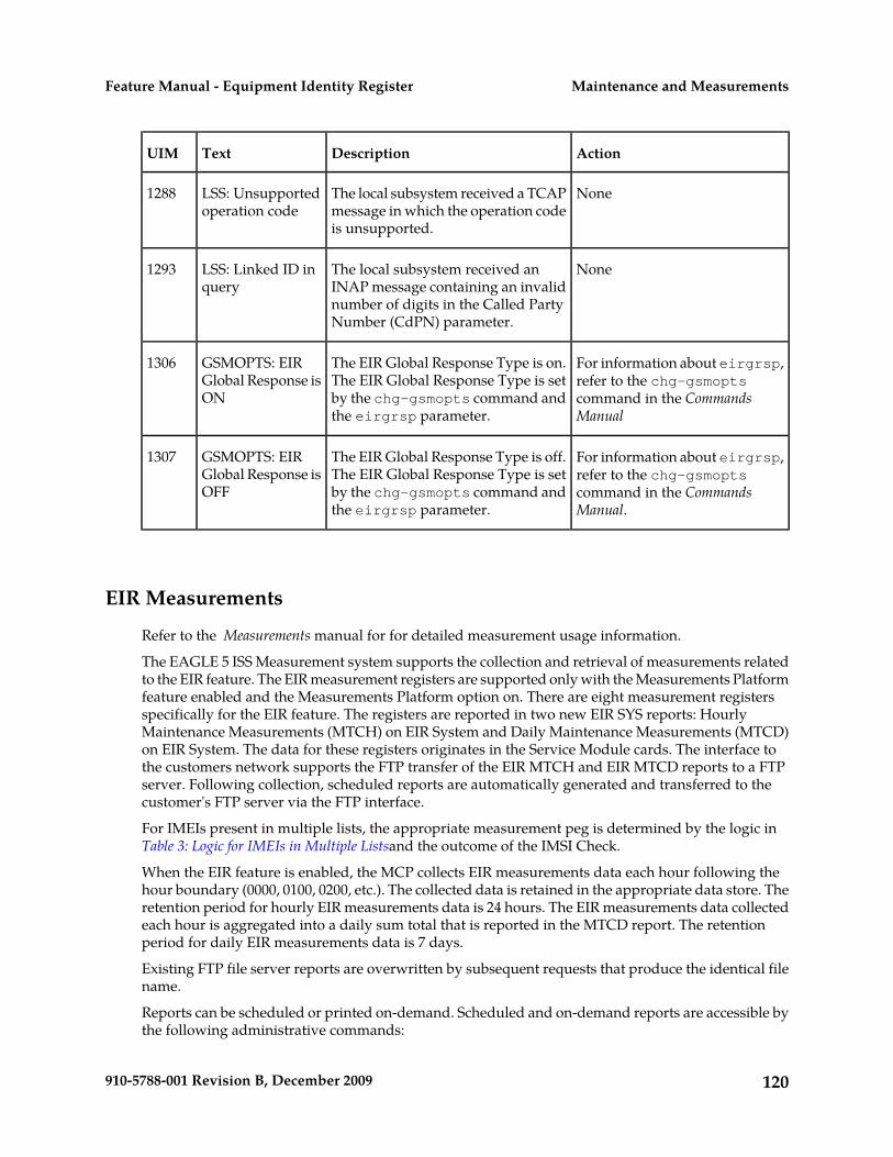
ActionDescriptionTextUIM
NoneThe local subsystem received a TCAPmessage in which the operation codeis unsupported.
LSS: Unsupportedoperation code
1288
NoneThe local subsystem received anINAP message containing an invalid
LSS: Linked ID inquery
1293
number of digits in the Called PartyNumber (CdPN) parameter.
For information about eirgrsp,refer to the chg-gsmopts
The EIR Global Response Type is on.The EIR Global Response Type is setby the chg-gsmopts command andthe eirgrsp parameter.
GSMOPTS: EIRGlobal Response isON
1306
command in the CommandsManual
For information about eirgrsp,refer to the chg-gsmopts
The EIR Global Response Type is off.The EIR Global Response Type is setby the chg-gsmopts command andthe eirgrsp parameter.
GSMOPTS: EIRGlobal Response isOFF
1307
command in the CommandsManual.
EIR Measurements
Refer to the Measurements manual for for detailed measurement usage information.
The EAGLE 5 ISS Measurement system supports the collection and retrieval of measurements relatedto the EIR feature. The EIR measurement registers are supported only with the Measurements Platformfeature enabled and the Measurements Platform option on. There are eight measurement registersspecifically for the EIR feature. The registers are reported in two new EIR SYS reports: HourlyMaintenance Measurements (MTCH) on EIR System and Daily Maintenance Measurements (MTCD)on EIR System. The data for these registers originates in the Service Module cards. The interface tothe customers network supports the FTP transfer of the EIR MTCH and EIR MTCD reports to a FTPserver. Following collection, scheduled reports are automatically generated and transferred to thecustomer's FTP server via the FTP interface.
For IMEIs present in multiple lists, the appropriate measurement peg is determined by the logic inTable 3: Logic for IMEIs in Multiple Listsand the outcome of the IMSI Check.
When the EIR feature is enabled, the MCP collects EIR measurements data each hour following thehour boundary (0000, 0100, 0200, etc.). The collected data is retained in the appropriate data store. Theretention period for hourly EIR measurements data is 24 hours. The EIR measurements data collectedeach hour is aggregated into a daily sum total that is reported in the MTCD report. The retentionperiod for daily EIR measurements data is 7 days.
Existing FTP file server reports are overwritten by subsequent requests that produce the identical filename.
Reports can be scheduled or printed on-demand. Scheduled and on-demand reports are accessible bythe following administrative commands:
120910-5788-001 Revision B, December 2009
Maintenance and MeasurementsFeature Manual - Equipment Identity Register

• chg-measopts - Used to enable or disable the automatic generation and FTP transfer of scheduledmeasurement reports to the FTP server.
• rept-stat-meas - Reports the status of the measurements subsystem including card locationand state, Alarm level, and Subsystem State.
• rept-ftp-meas - Manually initiates generation and FTP transfer of a measurements report fromthe MCPM to the FTP server.
• rtrv-measopts - Generates a user interface display showing the enabled/disabled status of allFTP scheduled reports.
The following Pegs per System measurement peg counts of EIR MSUs (Message Signaling Units) aresupported for the EIR feature (Table 26: Pegs for Per System EIR Measurements):
Table 26: Pegs for Per System EIR Measurements
UnitTypeDescriptionEvent Name
Peg countSystemTotal number of MAP_CHECK_IMEI messagesreceived.
IMEIRCV
Peg countSystemTotal number of searches that resulted in a matchwith a "White Listed" IMEI.
WHITEIMEI
Peg countSystemTotal number of searches that resulted in a matchwith a "Gray Listed" IMEI.
GRAYIMEI
Peg countSystemTotal number of searches that resulted in a matchwith a "Black Listed" IMEI.
BLACKIMEI
Peg countSystemTotal number of searches that resulted in a matchwith a "Black Listed" IMEI, but were allowed due toIMSI Check match.
BLKALIMEI
Peg countSystemTotal number of searches that resulted in a matchwith a "Black Listed" IMEI, and the IMSI in thedatabase did not match the IMSI in the message.
BLKNALIMEI
Peg countSystemTotal number of searches that resulted in a matchwith an "unknown" IMEI.
UNKNIMEI
Peg countSystemTotal number of searches that resulted in no matchin the database.
NOMTCHIME
Measurement Reports
Measurements are available with these report commands. Refer to the Commands Manual for detailedusage information.
121910-5788-001 Revision B, December 2009
Maintenance and MeasurementsFeature Manual - Equipment Identity Register

The commands are specified as follows, where xxx is a three-letter abbreviation for a day of the week(MON, TUE, WED, THU, FRI, SAT, or SUN) and yy is an hour of the day:
rept-ftp-meas:type=mtcd:enttype=eir[:day=xxx:period=specificEIR daily:
rept-ftp-meas:mtch:enttype=eir[:hh=yy:period=specificEIR hourly:
122910-5788-001 Revision B, December 2009
Maintenance and MeasurementsFeature Manual - Equipment Identity Register

GlossaryA
Application Data LoaderADL
ANSI-41 INP QueryAINPQ
American National StandardsInstitute
ANSI
An organization that administersand coordinates the U.S. voluntarystandardization and conformityassessment system. ANSI developsand publishes standards. ANSI isa non-commercial,non-government organizationwhich is funded by more than 1000corporations, professional bodies,and enterprises.
ANSI-41 Mobile Number PortabilityA-Port
Application ServerAS
A logical entity serving a specificRouting Key. An example of anApplication Server is a virtual switchelement handling all call processingfor a unique range of PSTN trunks,identified by an SS7DPC/OPC/CIC_range. Anotherexample is a virtual databaseelement, handling all HLRtransactions for a particular SS7DPC/OPC/SCCP_SSN combination.The AS contains a set of one or moreunique Application Server Processes,of which one or more normally isactively processing traffic.
Application Simulator
Test tool that can simulateapplications and/or SMSCs.
123910-5788-001 Revision B, December 2009

A
Application Trouble HandlerATH
B
Base StationBS
C
Country CodeCC
Calling Party AddressCgPA
The point code and subsystemnumber that originated the MSU.This point code and subsystemnumber are contained in the callingparty address portion of thesignaling information field of theMSU. Gateway screening uses thisinformation to determine if MSUsthat contain this point code andsubsystem number area allowed inthe network where the EAGLE 5 ISSis located.
Capability Point CodeCPC
A capability point code used by theSS7 protocol to identify a group offunctionally related STPs in thesignaling network.
Central Processing UnitCPU
Comma-separated valueCSV
The comma-separated value fileformat is a delimited data formatthat has fields separated by thecomma character and recordsseparated by newlines (a newlineis a special character or sequenceof characters signifying the end ofa line of text).
D
124910-5788-001 Revision B, December 2009
GlossaryFeature Manual - Equipment Identity Register

D
All data that can be administered bythe user, including cards, destination
Database
point codes, gateway screeningtables, global title translation tables,links, LNP services, LNP serviceproviders, location routing numbers,routes, shelves, subsystemapplications, and 10 digit telephonenumbers.
DatabaseDB
Direct CurrentDC
Device Control BlockDCB
Database Communication ModuleDCM
The DCM provides IP connectivityfor applications. Connection to ahost is achieved through an ethernetLAN using the TCP/IP protocol.
Destination Point CodeDPC
DPC refers to the scheme in SS7signaling to identify the receivingsignaling point. In the SS7 network,the point codes are numericaddresses which uniquely identifyeach signaling point. This point codecan be adjacent to the EAGLE 5 ISS,but does not have to be.
Database Service Module.DSM
The DSM provides large capacitySCCP/database functionality. TheDSM is an application card thatsupports network specific functionssuch as EAGLE ProvisioningApplication Processor (EPAP),Global System for MobileCommunications (GSM), EAGLE
125910-5788-001 Revision B, December 2009
GlossaryFeature Manual - Equipment Identity Register

D
Local Number Portability (ELAP),and interface to Local ServiceManagement System (LSMS).
E
Enhanced Global Title TranslationEGTT
A feature that is designed for thesignaling connection control part(SCCP) of the SS7 protocol. TheEAGLE 5 ISS uses this feature todetermine to which service databaseto send the query message when aMessage Signaling Unit (MSU)enters the system.
Equipment Identity RegisterEIR
A network entity used in GSMnetworks, as defined in the 3GPPSpecifications for mobile networks.The entity stores lists of InternationalMobile Equipment Identity (IMEI)numbers, which correspond tophysical handsets (not subscribers).Use of the EIR can prevent the useof stolen handsets because thenetwork operator can enter the IMEIof these handsets into a 'blacklist'and prevent them from beingregistered on the network, thusmaking them useless.
EAGLE Provisioning ApplicationProcessor
EPAP
F
File Transfer ProtocolFTP
A client-server protocol that allowsa user on one computer to transferfiles to and from another computerover a TCP/IP network.
G
Gigabyte — 1,073,741,824 bytesGB
126910-5788-001 Revision B, December 2009
GlossaryFeature Manual - Equipment Identity Register

G
GSM Flexible numberingG-Flex
A feature that allows the operator toflexibly assign individual subscribersacross multiple HLRs and routesignaling messages, based onsubscriber numbering, accordingly.
Generic Program LoadGPL
Software that allows the variousfeatures in the system to work. GPLsand applications are not the samesoftware.
GSM Mobile Number PortabilityG-Port
A feature that provides mobilesubscribers the ability to change theGSM subscription network within aportability cluster, while retainingtheir original MSISDN(s).
Global System for MobileCommunications
GSM
Global Title Routing IndicatorGT
Global Title AddressGTA
Global Title IndicatorGTI
Global Title TranslationGTT
A feature of the signaling connectioncontrol part (SCCP) of the SS7protocol that the EAGLE 5 ISS usesto determine which service databaseto send the query message when anMSU enters the EAGLE 5 ISS andmore information is needed to routethe MSU. These service databasesalso verify calling card numbers andcredit card numbers. The service
127910-5788-001 Revision B, December 2009
GlossaryFeature Manual - Equipment Identity Register

G
databases are identified in the SS7network by a point code and asubsystem number.
Graphical User InterfaceGUI
The term given to that set of itemsand facilities which provide theuser with a graphic means formanipulating screen data ratherthan being limited to characterbased commands.
H
Home Location RegisterHLR
Home Network Routing NumberPrefix
HOMERN
HardwareHW
I
Identity, identifierID
IS41 GSM MigrationIGM
International Mobile EquipmentIdentifier
IMEI
International Mobile SubscriberIdentity
IMSI
Intelligent Network ApplicationProtocol
INAP
INAP-based Number PortabilityINP
Tekelec’s INP can be deployed asa stand-alone or an integratedsignal transfer point/number
128910-5788-001 Revision B, December 2009
GlossaryFeature Manual - Equipment Identity Register

I
portability solution. With Tekelec’sstand-alone NP server, no networkreconfiguration is required toimplement number portability. TheNP server delivers a much greatersignaling capability than theconventional SCP-based approach.
Internet ProtocolIP
IP specifies the format of packets,also called datagrams, and theaddressing scheme. The networklayer for the TCP/IP protocol suitewidely used on Ethernet networks,defined in STD 5, RFC 791. IP is aconnectionless, best-effort packetswitching protocol. It providespacket routing, fragmentation andre-assembly through the data linklayer.
Integrated Services Digital NetworkISDN
In Service - NormalIS-NR
Integrated Services DigitalNetwork
ISDN
Integrates a number of services toform a transmission network. Forexample, the ISDN networkintegrates, telephony, facsimile,teletext, Datex-J, video telephonyand data transfer services,providing users with variousdigital service over a singleinterface: voice, text, images, andother data.
Integrated Signaling SystemISS
129910-5788-001 Revision B, December 2009
GlossaryFeature Manual - Equipment Identity Register

I
International TelecommunicationsUnion
ITU
L
Link Interface ModuleLIM
Provides access to remote SS7, IPand other network elements, such asa Signaling Control Point (SCP)through a variety of signalinginterfaces (DS0, MPL, E1/T1 MIM,LIM-ATM, E1-ATM, IPLIMx,IPGWx). The LIMs consist of a mainassembly and possibly, an interfaceappliqué board. These appliquésprovide level one and some leveltwo functionality on SS7 signalinglinks.
Signaling LinkLink
Signaling Link
Carries signaling within a Link Setusing a specific Association. A Linkcan belong to only one Link Set andone Association. There is generallyone Link per Association in a LinkSet.
Local Number PortabilityLNP
LNP Query ServiceLNPQS
Local SubsystemLSS
M
Mobile Application PartMAP
Maintenance and AdministrationSubsystem Processor
MASP
The Maintenance andAdministration Subsystem Processor
130910-5788-001 Revision B, December 2009
GlossaryFeature Manual - Equipment Identity Register

M
(MASP) function is a logical pairingof the GPSM-II card and the TDMcard. The GPSM-II card is connectedto the TDM card by means of anExtended Bus Interface (EBI) localbus.
The MDAL card contains theremovable cartridge drive and alarmlogic. There is only one MDAL cardin the Maintenance andAdministration Subsystem (MAS)and it is shared between the twoMASPs.
The point codes and subsystemnumbers of the service databases
Mated Application
that messages are routed to forglobal title translation.
Megabyte — A unit of computerinformation storage capacity equalto 1,048, 576 bytes.
MB
Mobile Country CodeMCC
Measurement Collection ProcessorMCP
This application is used by theMCPM card for the MeasurementsPlatform feature.
Measurement Collection and PollingModule
MCPM
The Measurement Collection andPolling Module (MCPM) providescomma delimited core STPmeasurement data to a remote serverfor processing. The MCPM is anEDSM with 2 GB of memory runningthe MCP application.
Multi-Purpose ServerMPS
131910-5788-001 Revision B, December 2009
GlossaryFeature Manual - Equipment Identity Register

M
The Multi-Purpose Server providesdatabase/reload functionality and avariety of high capacity/high speedoffboard database functions forapplications. The MPS resides in theGeneral Purpose Frame.
Mobile StationMS
The equipment required forcommunication with a wirelesstelephone network.
Mobile Switching CenterMSC
Mobile Station InternationalSubscriber Directory Number
MSISDN
The MSISDN is the network specificsubscriber number of a mobilecommunications subscriber. This isnormally the phone number that isused to reach the subscriber.
Message Signaling UnitMSU
The SS7 message that is sent betweensignaling points in the SS7 networkwith the necessary information toget the message to its destinationand allow the signaling points in thenetwork to set up either a voice ordata connection between themselves.The message contains the followinginformation:
• The forward and backwardsequence numbers assigned tothe message which indicate theposition of the message in thetraffic stream in relation to theother messages.
• The length indicator whichindicates the number of bytes themessage contains.
132910-5788-001 Revision B, December 2009
GlossaryFeature Manual - Equipment Identity Register

M
• The type of message and thepriority of the message in thesignaling information octet of themessage.
• The routing information for themessage, shown in the routinglabel of the message, with theidentification of the node thatsent message (originating pointcode), the identification of thenode receiving the message(destination point code), and thesignaling link selector which theEAGLE 5 ISS uses to pick whichlink set and signaling link to useto route the message.
Mobile TerminatedMT
All transmissions that reach themobile station and are accepted byit, such as calls or short messages.
The levels 1, 2, and 3 of the SS7protocol that control all the functions
MTP
necessary to route an SS7 MSUthrough the network.
N
Nature of Address IndicatorNAI
Standard method of identifyingusers who request access to anetwork.
NAI ValueNAIV
Number PlanNP
Numbering Plan ValueNPV
O
133910-5788-001 Revision B, December 2009
GlossaryFeature Manual - Equipment Identity Register

O
Operations, Administration, andMaintenance
OAM
The generic load program(application) that operates theMaintenance and AdministrationSubsystem which controls theoperation of the EAGLE 5 ISS.
Out of Service - MaintenanceOOS-MT
The entity is out of service and is notavailable to perform its normalservice function. The maintenancesystem is actively working to restorethe entity to service.
Originating Point CodeOPC
Operator Provisioning SystemOPS
P
Point CodePC
The identifier of a signaling point orservice control point in a network.The format of the point code can beone of the following types:
• ANSI point codes in the formatnetwork indicator-networkcluster-network cluster member(ni-nc-ncm).
• Non-ANSI domestic point codesin the format networkindicator-networkcluster-network cluster member(ni-nc-ncm).
• Cluster point codes in the formatnetwork indicator-networkcluster-* or network indicator-*-*.
• ITU international point codes inthe format zone-area-id.
• ITU national point codes in theformat of a 5-digit number
134910-5788-001 Revision B, December 2009
GlossaryFeature Manual - Equipment Identity Register

P
(nnnnn), or 2, 3, or 4 numbers(members) separated by dashes(m1-m2-m3-m4) as defined bythe Flexible Point Code systemoption. A group code is required(m1-m2-m3-m4-gc) when theITUDUPPC feature is turned on.
• 24-bit ITU national point codesin the format main signalingarea-subsignaling area-servicepoint (msa-ssa-sp).
The EAGLE 5 ISS LNP uses only theANSI point codes and Non-ANSIdomestic point codes.
Provisioning DatabasePDB
Provisioning Database ApplicationPDBA
There are two Provisioning DatabaseApplications (PDBAs), one in EPAPA on each EAGLE 5 ISS. They followan Active/Standby model. Theseprocesses are responsible forupdating and maintaining theProvisioning Database (PDB).
Provisioning Database InterfacePDBI
The interface consists of thedefinition of provisioning messagesonly. The customer must write aclient application that uses the PDBIrequest/response messages tocommunicate with the PDBA.
Processing ModulePM
Point-to-Point ProtocolPPP
R
135910-5788-001 Revision B, December 2009
GlossaryFeature Manual - Equipment Identity Register

R
The network management state of aroute, link set, or signaling link that
Restricted
is not operating properly and cannotcarry all of its traffic. This conditiononly allows the highest prioritymessages to sent to the databaseentity first, and if space allows,followed by the other traffic. Trafficthat cannot be sent on the restricteddatabase entity must be rerouted orthe traffic is discarded.
Request for CommentRFC
RFCs are standards-trackdocuments, which are officialspecifications of the Internet protocolsuite defined by the InternetEngineering Task Force (IETF) andits steering group the IESG.
Reliable Multicast TransportProtocol
RMTP
Routing NumberRN
A signaling path from an LSP to anRSP using a specified Link Set
Route
Remote Signaling PointRSP
Represents an SS7 network node(point code) that signaling must besent to. An RSP has an SS7 domain(ANSI, ITUI, ITUN), a point code,and an optional Adjacent ServerGroup.
Remote Signaling Point
A logical element that represents aunique point code within aparticular SS7 domain with whichthe SS7 application's Local SignalingPoint interacts.
136910-5788-001 Revision B, December 2009
GlossaryFeature Manual - Equipment Identity Register

R
Reset RequestRSR
Real Time DatabaseRTDB
S
Supervisory Audio ToneSAT
Signaling Connection Control PartSCCP
Service Control PointSCP
Service Control Points (SCP) arenetwork intelligence centers wheredatabases or call processinginformation is stored. The primaryfunction of SCPs is to respond toqueries from other SPs by retrievingthe requested information from theappropriate database, and sendingit back to the originator of therequest.
SCCP Routing ControlSCRC
Subscriber Identity ModuleSIM
An ID card the size of a credit cardfor GSM network subscribers, andis typically referred to as a chipcard or smartcard.
Service Nature of Address IndicatorSNAI
An internal G-Port parameter thatallows a user to specify how tointerpret the signaling connectioncontrol part (SCCP) called partyaddress (CdPA) GTA of aLOCREQ/SMSREQ message.
Signaling PointSP
137910-5788-001 Revision B, December 2009
GlossaryFeature Manual - Equipment Identity Register

S
A set of signaling equipmentrepresented by a unique point codewithin an SS7 domain.
SubsystemSS
Signaling System #7SS7
Subsystem NumberSSN
The subsystem number of a givenpoint code. The subsystem numberidentifies the SCP application thatshould receive the message, or thesubsystem number of the destinationpoint code to be assigned to the LNPsubsystem of the EAGLE 5 ISS.
A value of the routing indicatorportion of the global title translationdata commands indicating that nofurther global title translation isrequired for the specified entry.
Subsystem Prohibited networkmanagement message.
SSP
Subsystem Prohibited SCCP (SCMG)management message. (CER)
Signal Transfer PointSTP
STPs are ultra-reliable, high speedpacket switches at the heart of SS7networks, which terminate all linktypes except F-links. STPs are nearlyalways deployed in mated pairs forreliability reasons. Their primaryfunctions are to provide access toSS7 networks and to provide routingof signaling messages within andamong signaling networks.
T
138910-5788-001 Revision B, December 2009
GlossaryFeature Manual - Equipment Identity Register

T
Transaction Capabilities ApplicationPart
TCAP
Transfer Control ProtocolTCP
Transmission ControlProtocol/Internet Protocol
TCP/IP
Terminal Disk ModuleTDM
TransFer Allowed (Msg)TFA
TransFer Prohibited (Msg)TFP
A procedure included in thesignaling route management(functionality) used to inform asignaling point of the unavailabilityof a signaling route.
The point code defining adestination in the Destination PointCode table.
True Point Code
Translation Services ModuleTSM
Provides translation capability andGlobal Title Translation (GTT)implementation for the LocalNumber Portability (LNP) functionand is used for downloadinggateway screening tables to linkinterface modules (LIMs).
Translation Type.TT
Resides in the Called Party Address(CdPA) field of the MSU anddetermines which service databaseis to receive query messages. Thetranslation type indicates whichGlobal Title Translation table
139910-5788-001 Revision B, December 2009
GlossaryFeature Manual - Equipment Identity Register
T
determines the routing to aparticular service database.
U
Unsolicited Alarm Message.UAM
User Datagram ProtocolUDP
Unitdata Transfer ServiceUDTS
An error response to a UDTmessage.
User InterfaceUI
Unsolicited Information MessageUIM
V
Visitor Location RegisterVLR
VxWorks Signaling ConnectionControl Part
VSCCP
The application used by the ServiceModule card to support the G-Flex,G-Port, INP, AINPQ, EIR, A-Port,IGM, V-Flex, and LNP features. Ifthe G-Flex, G-Port, INP, AINPQ,EIR, A-Port, IGM, V-Flex, or LNPfeature is not turned on, and aService Module card is present, theVSCCP GPL processes normal GTTtraffic.
140910-5788-001 Revision B, December 2009
GlossaryFeature Manual - Equipment Identity Register