feature sensitive bas relief generation - max planck...
TRANSCRIPT

IEEE INTERNATIONAL CONFERENCE ON SHAPE MODELING AND APPLICATIONS (SMI) 2009 1
Feature Sensitive Bas Relief GenerationJens Kerber1, Art Tevs1, Alexander Belyaev2, Rhaleb Zayer3, Hans-Peter Seidel1
1MPI Informatik, Saarbrucken, Germany2Heriot-Watt University, Edinburgh, Scotland, UK
3INRIA, Nancy, France
(a) (b)
(c) (d)
Fig. 1. (a) a real world bas relief; (b) a geometric montage of3models; (c) a cubism like relief of the David head model; (d) anoriginal Picasso painting
Abstract—Among all forms of sculpture, bas-reliefis arguably the closest to painting. Although in-herently a two dimensional sculpture, a bas-reliefsuggests a visual spatial extension of the scene indepth through the combination of composition, per-spective, and shading. Most recently, there have beensignificant results on digital bas-relief generation butmany of the existing techniques may wash out highlevel surface detail during the compression process.The primary goal of this work is to address theproblem of fine features by tailoring a filteringtechnique that achieves good compression withoutcompromising the quality of surface details. As asecondary application we explore the generation ofartistic relief which mimic cubism in painting andwe show how it could be used for generating Picassolike portraits.
Keywords—shape deformation, computer art,sculpture, tone mapping
1. INTRODUCTION
Among all forms of sculpture, bas-relief is arguablythe closest to painting. Although inherently a two dimen-
sional sculpture, a bas-relief suggests a visual spatial ex-tension of the scene in depth through the combination ofcomposition, perspective, and shading. This suggestivepower of bas-relief has been recognized since antiquityand most of civilizations used it as a form of decoration.Nowadays bas relief remains indispensable to severalmodern applications e.g. coinage and packaging. It con-tinues to thrive into the digital age where it is suitablefor virtual shape decoration and computer art.
In recent research on automatic bas-relief generationfrom 3D scenes, the key ingredient is the so calledheight field (also known as depth map or range image)which is a 2.5D descriptions of the scene that encodesdistance information on a 2D regular gridz = I(x, y).Unfortunately the height information cannot be useddirectly for bas relief generation and a compressionstep is often required. Many of the existing bas reliefgeneration techniques differ mainly in the compressionstep and as a general remark they remain limited tosingle objects or very simple scenes. Additionally, thefine features of surfaces often get lost throughout thecompression process.
The primary goal of this work is to address theproblem of fine features by tailoring a filtering techniquethat achieves good compression without compromisingthe quality of surface details. On the application side weinvestigate the impact of perspective on the bas reliefgeneration. For this purpose we study the problem ofmerging multiple perspectives into one single scene, aproblem better known in painting as cubism. The resultsof our approach are illustrated by generating Picasso likeportraits.
2. RELATED WORK
A bas-relief generally exhibits a negligible spatialextent, but when contemplated from an almost orthog-onal vantage point it appears like a full 3D scene. Thestudy of this phenomenon in [1] suggests that undercertain transformations shading and shadowing remainunchanged in comparison to the initial scene, as long asthe perspective does not change significantly.
The generation of bas-relief from virtual scenes wasfirst studied in the pioneering work of [2]. In orderto infer depth, they rely on height fields along witha perspective foreshortening in the sense that objectscloser to the viewer are kept salient, whereas those in thebackground are mapped to a smaller z-range. Within this
framework, the desired compression ratio is achievedthrough a linear re-scaling. Although many of the majoraspects of bas-relief generation have been addressed inthis framework, the method is not of general use as thevisibility of small object features suffers to a great extentwhen linear re-scaling is applied.
Most recently, bas-relief generation has regained in-terest in the graphics community and there has beenan increasing effort to address some of the challengesmentioned above [3], [4], [5]. This development findsinspiration in high dynamic range compression (hence-forth HDRC). The purpose of HDRC is the compressionof a large luminance interval of a high dynamic rangeimage (HDRI) in such a way that it can be displayedon regular monitors without losing visually importantfeatures [6].
Bas-relief generation can be regarded as a geometricalanalogue of tone mapping. Instead of the luminanceinterval length it focuses on the size of the depth intervaland aims on producing a flat representation of the shapeby keeping significant details.
The method proposed in [3] relies on the combina-tion of a saliency measure and a feature enhancementtechnique. As the processing is performed in differentialcoordinates the bas relief is reconstructed as the solutionto a diffusion equation. The approaches by [4] and[5] operate in the gradient domain. They artificiallyenhance certain frequencies of the gradient images inorder to better preserve their visibility in the com-pressed outcome. Both techniques can be regarded asvariants of the gradient domain high dynamic rangecompression algorithm proposed by [7]. A discussionand a comparison of the above mentioned bas-reliefgeneration methods can be found in [8]. The most recentwork in this young research area is [9]. The authorsapply a modification of an image contrast enhancementtechnique. The difference to the other approaches is thatit operates immediately on the height field and usesgradient information only additionaly.
As geometric features are quite different from thosefound in images, the adaption of HDRC techniques toshapes is far from being straightforward. In this paperwe introduce a modified version of the tone mappingapproach initially presented in [10], which uses bilateralfiltering for decomposing an image into a base layerand a detail layer. This technique is initially targeted atreducing the contrast of a HDR images without losingintensity steps.
Cubism is a direction in painting which aims atcovering multiple perspectives in a single canvas. Theseperspectives partly overlap and the transition areas areblended such that a continuous impression comes up.The most famous representatives of this genre arePicasso’s portraits or Escher’s landscapes. In [11] atechnique for non photo realistic rendering is presentedwhich allows combining multiple simultaneous view-points in a single image. The author illustrates how thistechnique could be used for storytelling and infering
motion. In [12] the authors describe a method whichuses general linear cameras (GLCs), recently studiedand compared in [13], and a blending technique. Theuser is required to align the different renderings and thealgorithm generates seamless results.
Our bas-reliefs can serve as input for further applica-tions in computer art e.g. virtual carving embossment orengraving. They can serve as input for a semi automaticapproach [14] or assist an artist in producing a virtualpiece of art by a completely interactive tool [15].Moreover our results can be applied as displacementmaps for virtual shape decoration [16].
3. ALGORITHM DESCRIPTION
3.1 Overview
In this section we shall describe our bas relief gen-eration approach. The input for our algorithm could bean already generated height field or a full 3D scene. Inthe latter case, a height field could be obtained by read-ing the z-buffer after an orthographic or a perspectiveprojection.
The resulting depth maps generally are not of practicaluse for shape decoration as in general they exceed therange of available material depth and therefore they needto be flattened. The delicate task in bas relief generationis to devise suitable height filed compression withoutsacrificing the visual perception of important features.
Our method operates in the gradient domain andmakes use of different binary masks in order to identifypixels which belong to sensitive parts of the height field.The gradients are decomposed into a coarse and a detaillevel using the bilateral filter described in [10]. Thedetail part is then enhanced relative to the coarse com-ponents in such a way that sensitive features will remainperceivable in the result. The new gradient images arethen reassembled to obtain the final bas-relief. The usercan either specify the desired compression ratio or themaximal allowed value range for the bas-relief.
Our approach capitalizes on a fundamental propertyof bilateral filtering. In image processing, this type offiltering is known for its edge preserving capabilities. Aswe are operating in the gradient domain this propertytranslates to ridge preservation, as ridges are naturallythe edges of the gradient field. In other words, thefiltering preserves curvature extrema, which contain themost important information about the structure of theshape. Gaussian smoothing on the other hand as it isused for gradient frequency decomposition in [4] maywash out those ridges.
3.2 Preprocessing
Let I(x, y) be the input range image. It consists offoreground pixels which describe the distance of sceneobjects to the camera and a background area that is filledwith a certain default valueδ. We first extract a binarymask B(x, y) by labeling background pixels as zeros
2

and the foreground pixels as ones.
B(i, j) =
{
0, if I(i, j) = δ
1, else(1)
We normalize the input image in a way that thesmallest foreground value is mapped to the backgroundlevel, such that the interval ranges form 0 to a certainvalue.
I(x, y) = B(i, j) · (I(x, y) − Imin) (2)
WhereImin indicates the smallest foreground value ofI. This helps establishing the initial value range.
3.3 Relief Generation
After the preprocessing, we compute the gradientimagesIx andIy of I by a differential quotient in eachdimension. As we are in a discrete setting the formulasread as simple as:
Ix(i, j) ≈ I(i + 1, j) − I(i, j) (3)
Iy(i, j) ≈ I(i, j + 1) − I(i, j) (4)
Since background values are usually very differentfrom the foreground values we end up with rather largegradients along the outlines of scene objects. In [5],[4] this problem was addressed by introducing a userdefined threshold that sets all gradients above it to 0.We note that these discontinuities occur only along theobjects’ silhouette. Therefore, we can detect this areaautomatically with the help of the background maskgradients.
Bx(i, j) ≈ B(i + 1, j) − B(i, j)
By(i, j) ≈ B(i, j + 1) − B(i, j)
S(i, j) =
{
0, if |Bx(i, j)| = 1 or |By(i, j)| = 11, else
Here,S represents a binary mask that determines theboundary region and we can simply erase the silhouettepixels in the gradient images. In order to keep thisexposition concise we use the notationk ∈ {x, y} fromnow on.
I ′k = S ⊙ Ik (5)
Where, the⊙ operator indicates componentwise multi-plication.
In general, the resulting shape also exhibits largejumps on its surface which would negatively affect thequality of the result if they were preserved. On the onehand, they would keep the depth interval size artificiallyhigh and on the other hand large features would be toodominant in the result in a way that would drasticallyimpair the visibility of smaller features. Therefore, werely on an outlier detection to locate gradient entrieswhich differ largely from the other ones.
O(i, j) =
{
0, if |I ′k(i, j) − µk| > t ∗ σk
1, else(6)
Where,µk represents the mean value andσk the stan-dard deviation ofIk. This meansO is a binary maskthat covers the outliers fromboth dimensions. The usualvalues for tolerance factort are in the range[3, 10].Small values fort will lead to many pixels beingregarded as outliers which means losing almost all sharpfeatures. In the case of two objects which are partlyoccluding each other it may also occur that they appearto melt. A higher value fort, will cause a tolerancefor larger steps which impairs the visibility of smallerfeatures.
I ′′k is obtained by setting the corresponding values to0 like it is done above:
I ′′k = O ⊙ I ′k (7)
This eliminates unnecessary depth ranges and leads tocontinuous gradient images without jumps or disconti-nuities at the boundary and the scene objects. In thisway, the outlier detection adapts automatically to sceneelements without the need for absolute thresholdingparameters.
In order to compress the initial height field we have toreduce the amplitude of the gradient signal. This is doneby first applying an attenuation function which bringsthe entries closer together by diminishing larger valuesstronger and boosting small ones. In contrast to [5] whouse a logarithmic weighting function which compressesthe entries only by regarding their absolute value, weopted for applying the adaptive function proposed in [7]which takes into account the properties of the depthinterval.
A(X, i, j) =
{
0, ifX(i, j) = 0
a|X(i,j)| ·
(
|X(i,j)|a
)b
, else
I ′′′k = A(I ′′k ) ⊙ I ′′k
The parametera is chosen to be 10% of the averageabsolute value of all unmasked foreground pixels, ittags values which map to1 in the attenuation function.Pixels with entries whose absolute value is smaller thana are slightly enhanced whereas those above it are com-pressed. The second parameterb steers the attenuationrate. It is set to0.9 for all results substantiated in thispaper.
Now, that the gradient images are continuous andattenuated, the signals need to be decomposed andthe relative importance of small details needs to beenhanced. Therefore, we use bilateral filtering, whichis a well known technique in 2D image processing thatperforms edge-preserving smoothing. Using this filteringon the gradients is the core idea of our algorithm.Preserving gradient edges means preserving ridges.
The filter is described in the following equation:
BF (X, i, j) =
∑
m,n
Wm,ni,j (X)Xm,n
∑
m,n
Wm,ni,j (X)
Wm,ni,j (X) = Gσs
(||
(
i
j
)
−(m
n
)
||)Gσr(|Xi,j − Xm,n|)
3

Here,Gσsstands for a 1D Gaussian kernel with standard
deviationσs which is used to describe how much influ-ence thespatial distance has on the result, whereasGσr
steers how strong the difference of values (range) affectsit. m and n range from 0 to the maximal resolutionin X and Y respectively. For a detailed description werefer to [17] where several variations of this filter areinvestigated. The values for the deviation are choseadaptively, we recommend to useσs =
min(ResX ,Resy)16
andσr = Xmax−Xmin
10 , which are the default values forall results in this paper.
We now perform the decomposition in the followingway:
Coarsek = BF (I ′′′k ) (8)
Finek = I ′′′k − Coarsek (9)
The new gradient componentsJk for the final bas-reliefare now generated by modifying the relation betweenthe coarse and the fine components.
Jk = Finek + r ∗ Coarsek (10)
This leads to penalizing the coarse level details and arelative boosting of the fine details and ensures that thesmaller features will remain perceivable in the result.Typically the value for the relationr ∈ [0.05, 0.25]. r =0 would lead to exaggerated results which only containsmall features, spherical parts would appear either flator noisy.r = 1 does not change the relation at all andit would be the same as linear recalling which is notintended as described earlier.
Given the new gradient∇J =[
Jx
Jy
]
, we now haveto reconstruct its corresponding height field. In order toget back from the gradient domain to the spatial domain,we first compute its Laplacian∆J by adding the secondderivatives in both dimensions. We are still in a discretecase, so this can be done using finite differences. Since∆J is defined by a central difference, we have chosenthe backward difference for this case:
∆J = Jxx + Jyy (11)
Jxx(i, j) ≈ Jx(i, j) − Jx(i − 1, j) (12)
Jyy(i, j) ≈ Jy(i, j) − Jy(i, j − 1) (13)
The computation of a functionJ given its Laplacian isa so called Poisson problem and it is a fairly standardtechnique which require solving a sparse system oflinear equations.
3.4 Postprocessing
At the final stage, we proceed to the reassembly ofthe modified gradient components. As the boundary inthe Poisson reconstruction is given by the ”frame” ofour normalized height field,J may contain positive aswell as negative values. Therefore, a normalization isneeded for setting the background and the unreliablevalues along the object boundary to 0 again:
J(x, y) = B(i, j) · S(i, j) · (J(x, y) − Jmin) (14)
The depth entries ofJ now range form0 to Jmax
(maximal foreground value ofJ). In general this wouldnot exactly match the desired interval size. In the laststep a linear re-scaling to the correct ratio or range isperformed.
achieved range = Jmax (15)
λ =desired range
achieved range(16)
J = λ · J (17)
In this way we have produced a flattened versionJ of theinitial height fieldI which maps the smallest foregroundvalue to the background plane and elevates the restonly in slight manner. Thanks to our detail enhancementtechnique, all the fine structure remain perceivable in thefinal result.
For visualization purposes, we use a triangle mesh,based on a regular grid, for which the number of verticesis equal to the depth map resolution, and displace everyvertex by its corresponding height value.
4. ARTISTIC APPLICATIONS
The approach of cubism to painting consists of break-ing up the traditional vision of reality into multipleperspectives which are combined in a single composi-tion. The resulting images give the impression of beingviewed from many different angles at once. Needlessto say that cubism reflects a subtle aspect of humanperception, which is reliance on more than a singleglance.
We show how a slight modification of the above men-tioned main procedure can help generating cubism likerelief sculptures. We extend the height field capturingin a way that requires the user to rotate the model infrontal view, then a sequence of 13 height fields form-90 degree to 90 degree, which differ in 15 degree each,is automatically captured.
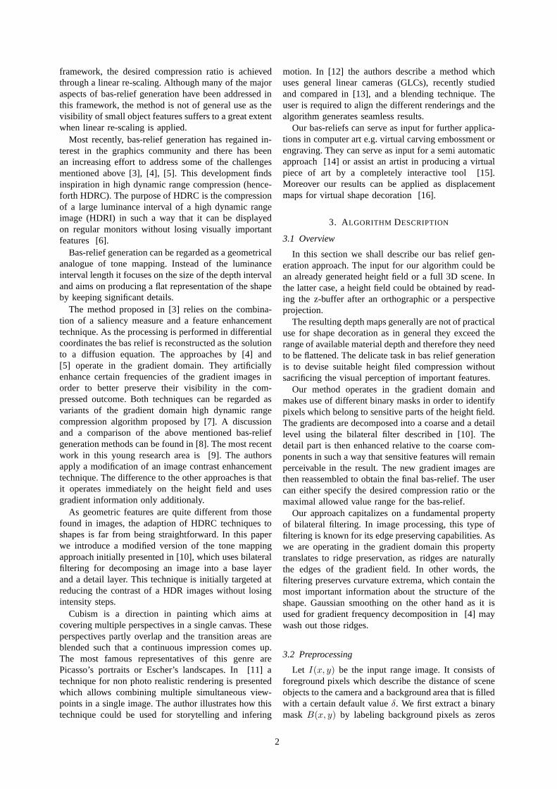
The user can now cut and paste multiple desiredperspectives into a new height field with any standardimage editing tool. The problem which arises is that thelength of the depth interval may vary throughout thedifferent perspectives and also might be affected by thevisibility of certain parts. These changes are rather largein general, as illustrated by the color coding in Figure 2.Nevertheless, to our advantage these differences causelarge discontinuities along the transition areas of twoor more perspectives, such that our gradient outlierdetection delivers those areas for free.
As described above, we set the corresponding largegradient values to0. The remaining issue is that afterreconstruction, the bas-relief exhibits a visible seambecause a null gradient leads to a flat transition withsteps on both sides which even emphasize the impres-sion of two distinct parts. Our experiments revealed thatusing a diffusion process or blurring those pixels in thespatial domain (after reconstruction) may lead to evenworse results, as they introduce additional steps betweenmodified and unmodified entries.
4
(a) (b) (c)
Fig. 2. (a) Color coded depth of the assembled shape; (b) zoomonthe back of the nose of relief without seam treatment; (c) improvedresult; full relief can be seen in Figure 1
Since the reconstruction requires central differencebefore reconstruction, each pixel which has an outlierin its direct neighborhood will be affected. To overcomethis problem we detect all affected gradient locationsand use a Gaussian filter in the gradient domain inorder to get smooth transitions which finally lead toa geometrically seamless result. We extend the outliermask by adding all pixels which are situated next to anoutlier. Therefore we convolveO with a 3x3 kernel:
F =
1 1 11 1 11 1 1
(18)
M = O ⊗ F (19)
M(i, j) =
{
1, M(i, j) = 90, else
(20)
This maskM marks the positions whose value afterreconstruction is still not reliable because of the outlierremoval. As we need to exclude the other0-entriesfor the blurring, we rely on the following discreteconvolution and modify the new gradient componentsJk accordingly:
Dσ(X, i, j) =
∑
m,n
Gσb(m,n)M(i-m,j-n)X(i-m,j-n)
∑
m,n
Gσb(m,n)M(i-m,j-n)
J ′k(a, b) = Dσ(Jk, a, b)
∀a, b : M(a, b) = 0
In this case,Gσbis a 2D Gaussian kernel andm, n are
its indices. For all cubism results presented in this paperσb is set to 8. As a straightforward extension, a usercan even drag and drop height fields of very differentmodels with largely varying spatial extensions into onelargegeometric collage, and the modified algorithm willproduce a bas-relief sculpture without nasty transitionareas. The tool itself is very tolerant, flexible and offersa lot of freedom to the user, but a meaningful creation ofthe input is mandatory for generating visually pleasingresults, this depends on the skill of the user in arrangingthe different perspectives or objects.
5. RESULTS AND DISCUSSION
All results presented here contain a slightly elevatedsilhouette mainly due to the final normalization step.This outline exaggeration is also used by real sculptingartists, to give the artwork a life-like impression and it
does not seem to be sunken in the background. If thisis not desired, or harms the depth range too much, aGaussian smoothing along the boundary can be used asfurther postprocessing. This is straightforward since theoutline location is already known.
All models were compressed so that the depth rangeis equal to 1% of their largest dimension (X or Y).The most crucial part for generating high quality bas-reliefs is the resolution of the discrete height field. Onthe one hand, a low resolution yields not so fine detailsand on the other hand it carries the risk that the outlierrecognition is not representative anymore as too manypixels may get mistakenly disregarded. Moreover, if asurface has details along its silhouette which possess awidth of only 1 pixel, then they may get removed bythe silhouette detection. To overcome these issues, theresolution need to be sufficiently high.
We want to stress that the outlier removal is notalways necessary, but depending on the model andpurpose, it turns out to be helpful. However, for thegeneration of seamless cubism like reliefs it is abso-lutely mandatory, because it removes the steps alongthe transition areas.
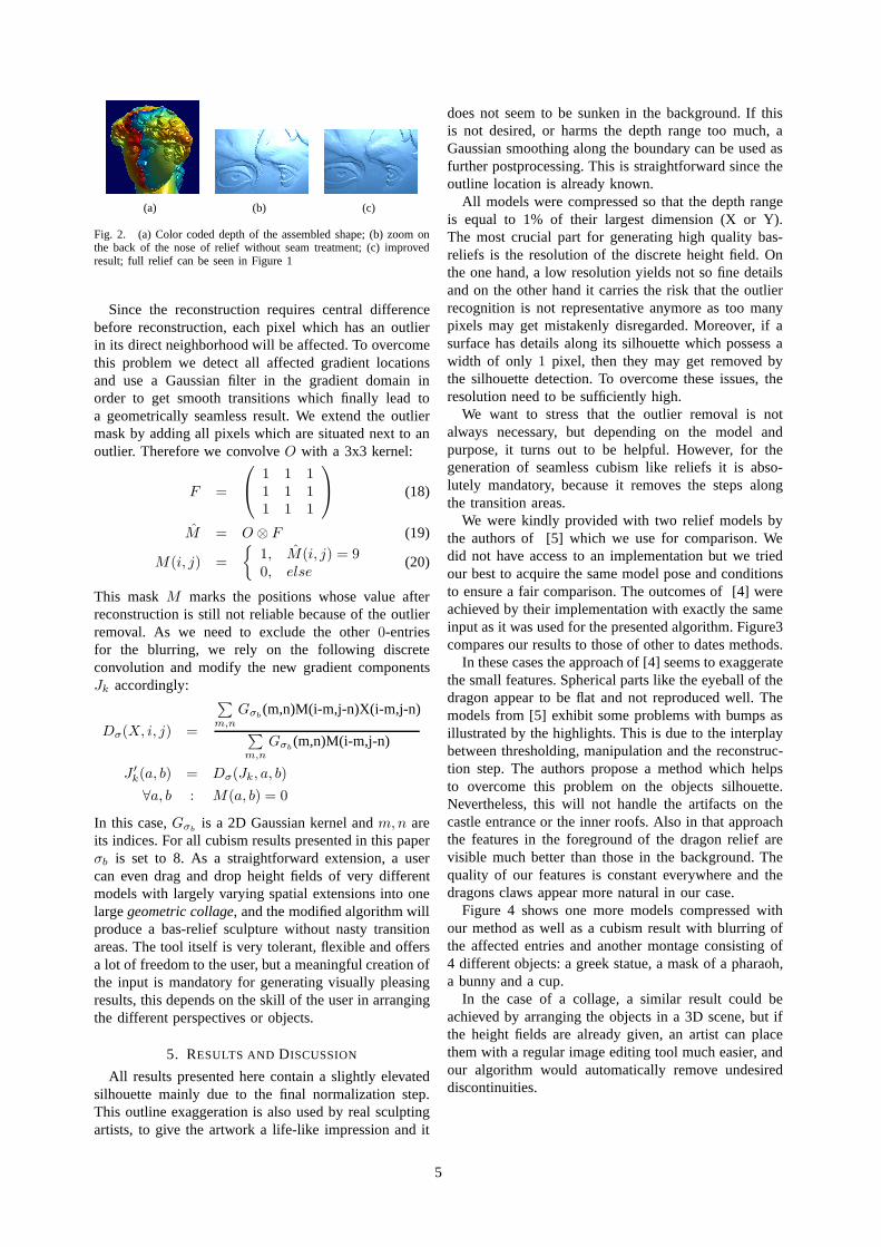
We were kindly provided with two relief models bythe authors of [5] which we use for comparison. Wedid not have access to an implementation but we triedour best to acquire the same model pose and conditionsto ensure a fair comparison. The outcomes of [4] wereachieved by their implementation with exactly the sameinput as it was used for the presented algorithm. Figure3compares our results to those of other to dates methods.
In these cases the approach of [4] seems to exaggeratethe small features. Spherical parts like the eyeball of thedragon appear to be flat and not reproduced well. Themodels from [5] exhibit some problems with bumps asillustrated by the highlights. This is due to the interplaybetween thresholding, manipulation and the reconstruc-tion step. The authors propose a method which helpsto overcome this problem on the objects silhouette.Nevertheless, this will not handle the artifacts on thecastle entrance or the inner roofs. Also in that approachthe features in the foreground of the dragon relief arevisible much better than those in the background. Thequality of our features is constant everywhere and thedragons claws appear more natural in our case.
Figure 4 shows one more models compressed withour method as well as a cubism result with blurring ofthe affected entries and another montage consisting of4 different objects: a greek statue, a mask of a pharaoh,a bunny and a cup.
In the case of a collage, a similar result could beachieved by arranging the objects in a 3D scene, but ifthe height fields are already given, an artist can placethem with a regular image editing tool much easier, andour algorithm would automatically remove undesireddiscontinuities.
5

(a) (b) (c)
(d) (e) (f)
Fig. 3. (left) results of the appraoch of Kerber et al., (middle) reliefs achieved with the presented approach, (right) results of the approach ofWeyrich et al.
(a) (b) (c)
Fig. 4. (a) Relief of the lion vase model(b) another cubism like effect on the David model (c) a collage being assembled of 4different objects
Figure 5 demonstrates the difference between apply-ing the bilateral filter in the spatial domain and usingit to filter in the gradient domain, as it is done here.Preserving edges like it is done in the spatial case isstrictly speaking counter productive for our compressionpurpoes because these edges are not visible form naorthogonal point of view and they cover keeping themkeeps the depth interval size unnecessarily high. (theinterval size for the Lucy model dropped from 407 to90 for the spatial case compared to 52 in the gradeintcase, before linear sclaing was applied). You can see this
difference in the transition between the raised arm andthe wing. The overall impression is quite ok but not aspleasing as the one achieved with our approach. Notethe problems at the left foot in the spatial result andcompare the richness of fine details of on the wings, thetorch and also the fingers in the two results.
A shortcoming of our approach is that it does only onedecomposition. In [5] a multi level approach is used inorder to allow stop band filtering. Such ideas are helpfulbecause one may allow a better distinction between veryfine details and noise.
6

(a) (b) (c) (d)
Fig. 5. Colorcoded height fields and the rendered reliefs achieved when filtering in the spatial (a+c) and the gradient domain (b+d)
Besides from the intended compression ratio, ourmethod requires only two input parameters from the user(at most). This makes our approach more attractive incomparison to existing approaches which may requirea trial and error tactic for setting the proper weightsfor the multiple layers of the Gaussian pyramid [5] inaddition to a threshold which can vary from model tomodel.
6. CONCLUSION
We presented a semi-automatic tool intended to sup-port the creation of bas relief from virtual scenes. Thekey technical contribution of our work is a filteringapproach which is aimed at preserving curvature extremaduring the compression process. In this way it is possibleto handle complex scenes with fine geometric detail.Furthermore, we have simplified the relief generationprocess so that it hardly requires any user intervention.On the artistic side we demonstrated how to use ourtechnique for generating cubism based bas relief scenes.The whole framework is intuitive, easy to implement andand independent of scene complexity.
ACKNOWLEDGEMENTS
We would like to thank the Stanford 3D ScanningRepository, Google 3D Warehouse, the XYZ RGBInc. and AIM@SHAPE for providing the models usedthroughout this paper. Special thanks to Tim Weyrichand Jia Deng for granting access to their results.
REFERENCES
[1] Peter N. Belhumeur, David J. Kriegman, and Alan L. Yuille,“The bas-relief ambiguity”,Int. J. Comput. Vision, vol. 35, no.1, pp. 33–44, 1999.
[2] Paolo Cignoni, Claudio Montani, and Roberto Scopigno, “Auto-matic generation of bas- and high-reliefs”,Journal of GraphicsTools, vol. 2, no. 3, pp. 15–28, 1997.
[3] Wenhao Song, Alexander Belyaev, and Hans-Peter Seidel,“Au-tomatic generation of bas-reliefs from 3d shapes”, inSMI ’07:Proceedings of the IEEE International Conference on ShapeModeling and Applications 2007, Washington, DC, USA, 2007,pp. 211–214, IEEE Computer Society.
[4] Jens Kerber, Alexander Belyaev, and Hans-Peter Seidel,“Featurepreserving depth compression of range images”, inProceedingsof the 23rd Spring Conference on Computer Graphics, MateuSbert, Ed., Budmerice, Slovakia, April 2007, pp. 110–114,Comenius University, Bratislava.
[5] Tim Weyrich, Jia Deng, Connelly Barnes, Szymon Rusinkiewicz,and Adam Finkelstein, “Digital bas-relief from 3d scenes”,ACMTrans. Graph., vol. 26, no. 3, pp. 32, 2007.
[6] Paul Debevec and Erik Reinhard, “High-dynamic-range imaging:Theory and applications”, SIGGRAPH 2006 Course #5, 2006,http://www.siggraph.org/s2006/main.php?f=conference&p=courses&s=5.
[7] Raanan Fattal, Dani Lischinski, and Michael Werman, “Gradientdomain high dynamic range compression”, inSIGGRAPH’02: Proceedings of the 29th annual conference on Computergraphics and interactive techniques, New York, NY, USA, 2002,pp. 249–256, ACM.
[8] Jens Kerber, “Digital art of bas-relief sculpting”, Masters thesis,Universitat des Saarlandes, August 2007.
[9] Xianfang Sun, Paul L. Rosin, Ralph R. Martin, and Frank C.Langbein, “Bas-relief generation using adaptive histogramequalisation”,IEEE Transactions on Visualization and ComputerGraphics, 2009.
[10] Fredo Durand and Julie Dorsey, “Fast bilateral filtering forthe display of high-dynamic-range images”, inSIGGRAPH’02: Proceedings of the 29th annual conference on Computergraphics and interactive techniques, New York, NY, USA, 2002,pp. 257–266, ACM.
[11] Andrew S. Glassner, “Cubism and cameras: Free-form optics forcomputer graphics”, Tech. Rep. MSR-TR-2000-05, MicrosoftResearch, January 2000.
[12] Jingyi Yu and Leonard McMillan, “A framework for multiper-spective rendering”, inRendering Techniques, Alexander Kellerand Henrik Wann Jensen, Eds. 2004, pp. 61–68, EurographicsAssociation.
[13] Andrew Adams and Marc Levoy, “General Linear Cameraswith Finite Aperture”, Grenoble, France, 2007, pp. 121–126,Eurographics Association.
[14] Alexander A. Pasko, Vladimir Savchenko, and Alexei Sourin,“Synthetic carving using implicit surface primitives”,Computer-Aided Design, Elsevier, vol. 33, no. 5, pp. 379–388, 2001.
[15] Alexei Sourin, “Functionally based virtual computer art”, inSI3D ’01: Proceedings of the 2001 symposium on Interactive3D graphics, 2001, pp. 77–84.
[16] Fabio Policarpo, Manuel M. Oliveira, and ao L. D. CombaJo“Real-time relief mapping on arbitrary polygonal surfaces”, inSIGGRAPH ’05: ACM SIGGRAPH 2005 Papers, New York, NY,USA, 2005, pp. 935–935, ACM.
[17] Sylvain Paris and Frdo Durand, “A fast approximation ofthebilateral filter using a signal processing approach”, Tech.Rep.MIT-CSAIL-TR-2006-073, MIT, 2006.
7