feedforward model based active force control of … · feedforward model based active force control...
TRANSCRIPT

Feedforward Model Based Active Force Control of Mobile Manipulator using MATLAB and MD Adams
SHARIMAN ABDULLAH, MUSA MAILAH, COLLIN TANG HOWE HING
Department of Applied Mechanics & Design Faculty of Mechanical Engineering
Universiti Teknologi Malaysia 81310 Skudai, Johor
MALAYSIA [email protected], [email protected], [email protected]
Abstract: - The paper highlights the potentials of using a feedforward model based Active Force Control (AFC) as a disturbance rejection scheme in the motion control of a mobile manipulator (MM). The AFC part creates a force or torque feedback within the dynamic system to allow for the compensation of the sudden disturbance introduced into the system prior to relaying the signal to the conventional outerloop position controller employing a resolved acceleration control (RAC) configuration, thereby increasing the robustness of the MM system. The proposed AFC-based model also shows a faster computational performance by manipulating the estimated inertia matrix (IN) of the system instead of considering the entire system dynamic model. A feedforward element in the form of a simplified model of the dynamic system is implemented to complement the IN for a better trajectory tracking performance of the system. The simulation was performed and the results were compared with the computed torque control (CTC) with RAC scheme to benchmark the performance and robustness of the AFC-based counterpart. The MM consists of a skid steering four wheel nonholonomic mobile platform with a three degree-of-freedom (DOF) articulated manipulator attached on top. With the proposed controller incorporated into the system, the tracking performance of the MM is considerably enhanced with increased workspace capacity and better operation dexterity. Key-Words: - Active force control, Feedforward model based control, Mobile manipulator, Robust control, Tracking Performance 1 Introduction Mobile manipulator is better understood as a combination of a mobile platform and an arm manipulator attached to it. There is significant research on mobile robot or mobile platform in recent years and developments have been made in areas related to localization, control and others. However, the actual implementation of a mobile robot in real world is rather limited. Perhaps the lack of task that a mobile robot can perform is the limiting factor towards the possible implementation of a mobile robot in real world. Therefore, the addition of a robotic arm or manipulator to a mobile robot is the most natural thing to do. However, adding a manipulator with several DOF to a mobile robot increases the complexity of the system.
The precision and reliability of a typical industrial robot have become increasingly an essential part in modern manufacturing processes. These industrial robots have a wide application range, expanding from a simple process like point-to-point material transfer to a more complicated
operation, like continuous trajectory tracking, spray painting, and welding. The fixed base of the industrial robot arm limits the working range and flexibility of the system. By adding mobility to the robot arm, it can significantly increase the working range and flexibility of the robot, but at the same time increase the control system complexity. Most of the recent industrial manipulators are still using proportional-integral-derivative (PID) position controller by neglecting the dynamics of the manipulator. This approach is sufficient, since most of the parameters surrounding the manipulator are in fact controllable [1, 2]. Adding the mobility to the manipulator, however, changes the system dynamics and exposes the system to more environmental noises; hence, a more robust and effective control system is required.
A research project from Aalborg University demonstrated a MM concept that can operate in a flexible manufacturing environment [3]. The MM nicknamed “Little Helper” was developed to promote the idea of an autonomous manufacturing
WSEAS TRANSACTIONS on SYSTEMS Shariman Abdullah, Musa Mailah, Collin Tang Howe Hing
E-ISSN: 2224-2678 314 Issue 6, Volume 12, June 2013

assistant which can be integrated into an industrial production environment. The “Little Helper” system is completely decoupled implying that while the robot is moving around the environment, only the mobile platform is enabled. When using the manipulator, then the mobile platform will be stationary. This decoupled system allows for the implementation of the existing technology on mobile robots and robot manipulators. The focus is on developing the navigation and localization of the mobile platform while the arm manipulator control can be used as it is. The dynamic system of the MM is coupled which means that any movement from the mobile platform will affect the arm manipulator and vice versa as presented by Yamamoto and Yun [4]. In their research, they show the dynamic model of a nonholonomic MM, taking into consideration the interaction between the two. A nonlinear feedback control using an input output linearization technique was performed and the tracking performance of the system studied. In the nonlinear feedback control, the MM nonlinear dynamic model with compensation for the dynamic interaction between the mobile platform and manipulator shows better tracking error performance.
A model based control which is similar to computed torque method was introduced to minimize the tracking error and was shown to withstand a minimum variation in the parameters value [5]. The model based control uses the dynamic model of the MM to compute the required torque for each generalized coordinate. The torque computed from the dynamic model is then fedback into the system which linearizes the control system if the exact parameters of the dynamic model are known. The model based control is coupled with the proportional and derivative (PD) position control. It shows better tracking performance when compared to using only the ‘pure’ PD control. However, the performance is limited to a small number of uncertain parameters and cannot reject the effect of large disturbance. The model based control method heavily relies on the modelled dynamic system and in real world application, an exact dynamic model is almost impossible to derive and the computational power that is needed could be expensive. A more robust controller based on the Lyapunov second method was determined that is based on the global convergence of the tracking errors to zero and boundedness of the parameter estimates [6, 7]. Using the Lyapunov second method, the system stability can be determined by showing that the Lyapunov function is positive definite and continuous and the derivative of the Lyapunov function is negative semi definite along the function
trajectories. A global tracking controller that is based on the system dynamic tracking error and asymptotically converges to the desired trajectory was proven by the Lyapunov second method and extended Barbalat lemma in [8-12]. However, in the Lyapunov second method, finding a suitable Lyapunov function can prove to be a difficult task and adjusting the control law according to the Lyapunov function sometimes requires a lot of trial runs.
Neural network (NN) based control is a popular method used to control complex nonlinear dynamic system and increase the disturbance rejection capability of the MM. The NN based control typically used an NN estimator to identify the uncertainty of the nonlinear dynamics and compensate for it. Two NN controllers were used to control the arm and mobile platform separately in [13]. The NN compensator was determined on-line with no preliminary learning stage required. A suitable Lyapunov function was determined based on the system dynamic error for each of the mobile platform and the manipulator. The proposed NN controller shows ability to reject the presence of some bounded disturbances but the experimental setup only considers a fixed manipulator with fixed base. In another study, an adaptive NN control based on the radial basis function (RBF) was used to find a linearly parameterized approximator to approximate the system unknown nonlinearity [14-18]. The proposed system considers the MM as a whole unit where one NN controller was used to control the MM. The simulation result shows the ability of the proposed system to asymptotically converge to the desired trajectories.
An interesting approach toward solving the MM control problem was introduced by a number of researchers using the model predictive control (MPC) [19-21]. In the proposed system, it was shown that the MPC can be implemented under strict hardware configuration of a physical MM. A quadratic programming was employed to optimize the control input and the experimental results show that the proposed controller could lead the MM end effector to the desired target and also adapt to a sudden change of the end effector target to a new target. However, the research did not show any results regarding the robustness of the system when dealing with disturbance or uncertainty.
Active force control (AFC) is known to be capable of controlling the dynamic system with internal feedback force or torque, which is continuously estimated from the system disturbance response in order to compensate for the effects of the disturbances, thereby further improving the
WSEAS TRANSACTIONS on SYSTEMS Shariman Abdullah, Musa Mailah, Collin Tang Howe Hing
E-ISSN: 2224-2678 315 Issue 6, Volume 12, June 2013

robustness of the system. AFC was combined with the resolved acceleration control (RAC) which is used to control a differentially driven MM with a two-link planar arm in [22]. The RAC manages the kinematic aspect of the system while the AFC section combines with a proportional-integral (PI) control to manage the dynamic part of the system. A torque sensor and an accelerometer are used to monitor the parameters of the dynamic system in real time. The main advantage of the AFC is the ability to simplify the dynamic model of the system into an estimated inertia matrix (IN) by utilizing the torque feedback within the dynamic system.
A number of methods have been proposed to determine the appropriate IN of any particular system. A more robust form of AFC was introduced to estimate the suitable IN using various intelligent schemes including neural network, fuzzy logic, iterative learning and knowledge based method [23-27]. A knowledge based fuzzy (KBF) was further introduced to estimate the value of the IN in [28]. In the research, it was shown that a repeating pattern is obtained such that when the actual velocity of a joint decreases, the tracking error correspondingly increases and vice versa. This observation further shows that the increase in error can affect the inertial parameter of the system. This leads to the development of a fuzzy based law to estimate the IN of the system. The results from both simulation and practical experimentation show promising robustness and effectiveness in the control of the MM. However, the additional elaborate and intricate algorithm design applied to a basic AFC system increases the complexity of the overall proposed AFC-based scheme. Thus, there is a need for a trade-off between the superior robustness performance and real world application.
In this paper, a feedforward control is proposed to be combined with the AFC loop in view to compensate for the system inertia matrix, IN. It has been shown that the feedforward control assists various motion control procedures and improve the tracking performance [29]. The superiority of the AFC section in the motion control of the MM to continuously track a prescribed trajectory is highlighted. As a benchmark, a comparison with CTC technique was performed. In this study, the MM consists of a mobile platform with a two DOF differentially driven system and a three DOF articulated manipulator, mounted on top of the mobile platform. Fig. 1 shows a schematic of a mobile platform.
Fig. 1: A representation of the mobile platform The mobile platform is located at (xm, ym)
coordinate, defined at the centre of the robot, Om, in between the two wheels. φm represents the heading angle. The distance between the two wheels of the mobile platform is denoted as b, whereas the wheel radius is R. The distance between Om and the base of the arm manipulator Or is p. The tip position of the manipulator end effector is represented as (xE, yE, zE) and the joint angle of the manipulator is (θ1, θ2, θ3). Fig. 2 illustrates the arm manipulator while Fig. 3 depicts a 3D model of the MM.
Fig. 2: Schematic of the arm manipulator
Fig. 3: A 3D model of the MM
2R
p φ
m
b
Om Or
a2
a3 θ3
θ2
θ1
d3 d1
d2
WSEAS TRANSACTIONS on SYSTEMS Shariman Abdullah, Musa Mailah, Collin Tang Howe Hing
E-ISSN: 2224-2678 316 Issue 6, Volume 12, June 2013

2 Preliminaries The dynamic model and the trajectory generation for the MM are important aspects to be considered in demonstrating the robustness and the trajectory tracking ability of the MM. Although the MM configuration is using the skid steering four wheel design, it is assumed that this configuration have the same effect as a differential drive with two wheels setup. 2.1 Dynamic Model of MM Consider the dynamic equation of a nonholonomic mobile platform as:
( ) ( , ) ( ) ( ) ( )Tp p p rq q q q q q q qλ τ+ + + =M C A R B
(1)
Where q ∈ R4x1 represents the generalized coordinate of mobile platform, qr ∈ R3x1 represents the generalized coordinate of arm manipulator, Mp(q) ∈ R4x4 is the symmetric and positive definite inertia matrix of mobile platform, 4 1( , )p q q R ×∈C is the centripetal and Coriolis matrix of the mobile platform, λ is the Lagrange multiplier used to reflect the existence of the constraint forces in the mobile platform, A(q) ∈ R2x4 is the constraint matrix, B(q) is the input transformation matrix and τ is the torque input. Rp(q) ∈ R4x4
is the inertia matrix which represents the mobile platform dynamics on the manipulator. The mobile platform is subjected to three constraints which cannot move in the lateral direction and both wheels cannot roll and slip. The constraints equation can be written as:
sin cos 0m mx yϕ ϕ− = (2)
cos sin ( )2m m r lRx yϕ ϕ θ θ− = +
(3)
The two constraint equations can be written in
matrix form:
( ) 0q q =A (4) Where
sin cos 0 0( )
cos sin / 2 / 2q
R Rϕ ϕϕ ϕ
− = −
A
It is possible to find a matrix ST formed by a linearly independent vector field spanning the null space of A where:
( ) ( ) 0T Tq q =A S (5) and there exists a smooth vector η such that:
( )q q η= S (6)
( ) ( )q q qη η= +S S (7) Where
T
r lη θ θ = and [ ]Tm m r lq x y θ θ=
Using (5) and (7) and by multiplying (1) with
S(q)T, we can get:
( )T T Tp p p p p rqη η τ+ + = −S M S M S C S B S R
(8)
The dynamic equation of the arm manipulator can be given by:
( ) ( , ) ( ) ( , )r r r r r r r r r rq q q q q q q q+ + = −M C Gτ R
(9) Similarly, by substituting (7) into (9), we can get:
( )r r r r r r rq q η η+ + = − −M C Gτ R S R S
(10) where Mr(q) ∈ R3x3 is the symmetric and positive definite inertia matrix of arm manipulator 3 1( , )p q q R ×∈C is the centripetal and Coriolis matrix of the arm manipulator, G(qr) is the gravity effect on the MM arm, Rr(q) = Rp(q)T is the inertia matrix which represents the arm manipulator dynamics on the mobile platform. Considering the generalized coordinate for the MM as q = [θr θl θ1 θ2
θ3], the generalized dynamic equation of the MM can be given as:
( ) ( , ) ( )q q q q q τ+ + =M C G P (11)
Where
( )T T
p p
r r
q
=
S M S S RM
R S M,
00
T =
S BP
I and
( , )T T
p p
r r
q qη
η − −= − −
S M S S CC
C R S
WSEAS TRANSACTIONS on SYSTEMS Shariman Abdullah, Musa Mailah, Collin Tang Howe Hing
E-ISSN: 2224-2678 317 Issue 6, Volume 12, June 2013

Fig 4: Block diagram of a feedforward model based AFC controller
Fig 5: Block diagram of CTC
2.2 Controller Design Fig 4 shows the block diagram of an AFC controller. θref is represented by a vector of the generalized coordinate of the MM, i.e., (θ1,θ2,θ3,θr,θl). Ktn is the motor torque constant for each joint and wheel and Q is the vector of external disturbances applied to the MM system. One of the advantages of the AFC-based scheme is its ability to reduce the mathematical complexity of the modelled inertia matrix (IN) of the system. A set of parameters is used to replace the complex mathematical model of the IN. In this study, the IN parameters were estimated using a crude approximation method. Since the optimum value of IN is fixed, it can only be effective if the nonlinearity of M(q) is not too complex. If the M(q) is highly nonlinear, then some other methods of estimation are needed. In this paper, a feedforward value of M(q) is proposed to be combined with the crude approximation method to compensate for the nonlinear effect. To highlight the advantages of the proposed AFC method, a more conventional control method which is known as the computed torque controller (CTC) was considered for benchmarking purpose.
Both the AFC and CTC methods are required to be coupled with a position controller such as PID and resolved acceleration controller (RAC) to provide the position control of the system. The CTC scheme shown in Fig 5 relies heavily on the accurate modelling of the system dynamics. The MM dynamic model in (11) was used to implement the CTC. 3 Simulation Results The simulation was performed using MD Adams for the dynamic model simulation and MATLAB/Simulink for the control system implementation. A 3D solid model of the proposed MM was designed in MD Adams platform. The MM model in MD Adams receives five input torques for each of the revolute joint (θr,θl,θ1,θ2,θ3) from MATLAB/Simulink and outputs the displacement, velocity and acceleration of the revolute joints to MATLAB/Simulink environment. The proposed control algorithm was implemented in MATLAB/Simulink. The parameters used in the simulation is mp = 2.9 kg, mw = 1.5 kg, m1 = 1 kg, m2 = 1.3 kg, m3 = 0.25 kg, a2 = 0.3 m, a3 = 0.36 m, p = 0.1 m, R = 0.2 m, b = 0.29 m where mp is the mass of the platform, mw is the mass of the wheel with
actθ
IN/Ktn Mobile Manipulator
Model
IN
Q
refθ
actθ
s1
s1
+ -
actθ
Kd Kp
refθ
refθ
+ -
+ -
+ +
+ + + +
AFC
M(q)-1
+
1/Ktn
Ktn
actθ
M(q) Mobile Manipulator
C(q,q)+G(q)
Q
refθ
s1
s1
actθ
Kd Kp
refθ
refθ
+ -
+ -
+ +
+ + +
+
WSEAS TRANSACTIONS on SYSTEMS Shariman Abdullah, Musa Mailah, Collin Tang Howe Hing
E-ISSN: 2224-2678 318 Issue 6, Volume 12, June 2013
motor, m1 is mass of joint 1 of arm manipulator, m2 is the mass of joint 2 of arm manipulator.
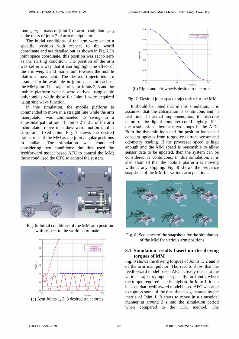
The initial conditions of the arm were set to a specific position with respect to the world coordinate and are detailed out as shown in Fig 6. In joint space coordinate, this position was set to zero as the starting condition. The position of the arm was set in a way that it can highlight the effect of the arm weight and momentum towards the mobile platform movement. The desired trajectories are assumed to be available in joint-space for each of the MM joint. The trajectories for Joints 2, 3 and the mobile platform wheels were derived using cubic polynomials while those for Joint 1 were acquired using sine wave function.
In this simulation, the mobile platform is commanded to move in a straight line while the arm manipulator was commanded to swing in a sinusoidal path at joint 1. Joints 2 and 3 of the arm manipulator move in a downward motion until it stops at a fixed point. Fig. 7 shows the desired trajectories of the MM as the joint angular positions in radian. The simulation was conducted considering two conditions: the first used the feedforward model based AFC to control the MM; the second used the CTC to control the system.
Fig. 6: Initial conditions of the MM arm position
with respect to the world coordinate
(a) Arm Joints 1, 2, 3 desired trajectories
(b) Right and left wheels desired trajectories
Fig. 7: Desired joint-space trajectories for the MM
It should be noted that in this simulation, it is assumed that the calculation is continuous and in real time. In actual implementation, the discrete nature of the digital computer could slightly affect the results since there are two loops in the AFC. Both the dynamic loop and the position loop need constant updates from torque or current sensor and odometry reading. If the processor speed is high enough and the MM speed is reasonable to allow sensor data to be updated, then the system can be considered as continuous. In this simulation, it is also assumed that the mobile platform is moving without any slipping. Fig. 8 shows the sequence snapshots of the MM for various arm positions.
Fig. 8: Sequence of the snapshots for the simulation of the MM for various arm positions
3.1 Simulation results based on the driving
torques of MM Fig. 9 shows the driving torques of Joints 1, 2 and 3 of the arm manipulator. The results show that the feedforward model based AFC actively reacts to the various trajectory inputs especially for Joint 2 where the torque required is at its highest. In Joint 1, it can be seen that feedforward model based AFC was able to supress some of the disturbances generated by the inertia of Joint 1. It starts to move in a sinusoidal manner at around 2 s into the simulation period when compared to the CTC method. The
WSEAS TRANSACTIONS on SYSTEMS Shariman Abdullah, Musa Mailah, Collin Tang Howe Hing
E-ISSN: 2224-2678 319 Issue 6, Volume 12, June 2013

feedforward model based AFC also shows its ability to follow the Joint 1 sinusoidal trajectory input more accurately compared to the CTC counterpart.
(a) Feedforward model based AFC
(b) CTC
Fig. 9: Driving torques of Joints 1, 2 and 3 of the MM
(a) Feedforward model based AFC
(b) CTC
Fig. 10: Driving torques of the left and right wheels of the MM
In Fig. 10, the driving torques of the left and
right wheels of the MM is shown. Fig. 10(a) clearly shows the interaction effect between the arm of the MM and the MM wheels. The feedforward model based AFC compensates the effect of the arm manipulator sinusoidal movement by providing an almost similar sinusoidal driving torques on the left and right wheels. This effectively allows the MM to
continue to move straight regardless of its arm manipulator motion. Fig. 10(b) in comparison shows the driving torques for the right and left wheels of the MM using CTC method. In this method, it can also be seen that the CTC is reacting less favourably to the sinusoidal effect of the MM arm motion in comparison to the feedforward AFC method, thereby producing less effective performance in maintaining the small tracking error of the MM movement. 3.2 Simulation results based on the error
tracking performance of MM Fig. 11 shows the tracking errors for Joints 1, 2 and 3 of the MM. The feedforward model based AFC shows improvement in the tracking performance compared to the CTC method. The tracking error result for the MM arm at Joint 1 which is moving in a sinusoidal swinging motion is also clearly shown in the figure. Although the tracking error differences between the AFC and CTC is not significant, the improvement in terms of less noise vibration generated by feedforward model based AFC can be visibly seen.
0 5 10-0.04
-0.03
-0.02
-0.01
0
0.01
0.02
0.03
0.04
0.05
Time(Sec)
Trac
king
erro
r (R
ad)
Arm Joint 1Arm Joint 2Arm Joint 3
(a) Feedforward model base AFC
0 5 10-0.2
-0.1
0
0.1
0.2
0.3
0.4
0.5
Time (Sec)
Trac
king
erro
r (R
ad)
Arm Joint 1Arm Joint 2Arm Joint 3
(b) CTC
Fig. 11: Position tracking errors for Joints 1, 2 and 3 of the MM
The tracking error result for the MM arm at Joint
2 which is moving in a downward motion and then
WSEAS TRANSACTIONS on SYSTEMS Shariman Abdullah, Musa Mailah, Collin Tang Howe Hing
E-ISSN: 2224-2678 320 Issue 6, Volume 12, June 2013
is stopped at a fixed position is also depicted in the figure. The control of Joint 2 is where the driving torque of the MM is deemed at its highest. From the results, it can be seen that the feedforward AFC performs almost the same as the CTC with a slightly better disturbance rejection performance. The MM arm Joint 3 also moves in a downward motion and then is stopped at a fixed position. The control of Joint 3 is where the dynamic interaction between the arm and mobile platform is at its highest. Here, it can be seen that feedforward AFC performs better than the CTC in terms of the tracking error and disturbance rejection performance. In the CTC method, the disturbance generated when the MM started to move causes severe vibratory responses of Joint 3 while the feedforward model based AFC shows considerable improvement in the tracking error performance. Fig. 12 shows the tracking error for the left and right wheels of the MM.
0 5 10-0.1
-0.08
-0.06
-0.04
-0.02
0
0.02
0.04
0.06
0.08
Time(Sec)
Trac
king
erro
r(Rad
)
RightWheelLeftWheel
(a) Feedforward model based AFC
0 5 10-0.7
-0.6
-0.5
-0.4
-0.3
-0.2
-0.1
0
0.1
0.2
0.3
Time (Sec)
Trac
king
erro
r (R
ad)
RightWheelLeftWheel
(b) CTC
Fig. 12 Position tracking errors for left and right wheel of MM
Significant improvement in terms of the tracking
error performance can be seen in the control of the left and right wheels of the MM. In the CTC method, the controller can be seen having large swing of displacement in trying to follow the sinusoidal effect of the arm. In the feedforward model based AFC, a better tracking error
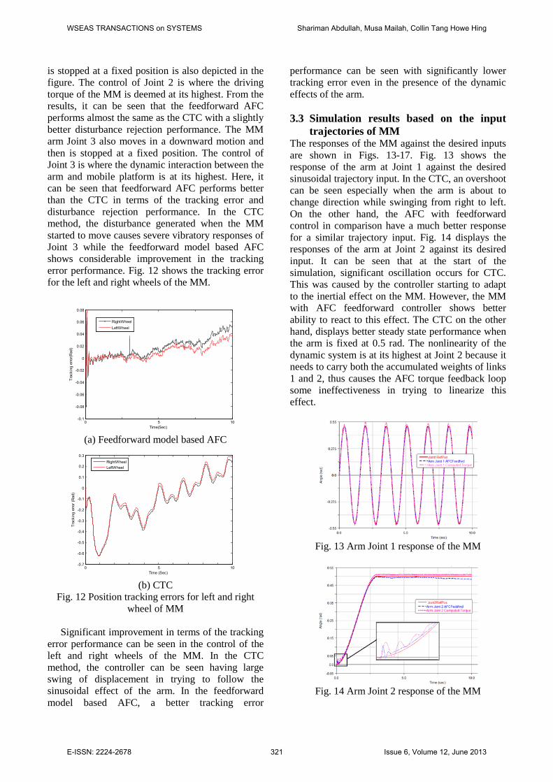
performance can be seen with significantly lower tracking error even in the presence of the dynamic effects of the arm. 3.3 Simulation results based on the input
trajectories of MM The responses of the MM against the desired inputs are shown in Figs. 13-17. Fig. 13 shows the response of the arm at Joint 1 against the desired sinusoidal trajectory input. In the CTC, an overshoot can be seen especially when the arm is about to change direction while swinging from right to left. On the other hand, the AFC with feedforward control in comparison have a much better response for a similar trajectory input. Fig. 14 displays the responses of the arm at Joint 2 against its desired input. It can be seen that at the start of the simulation, significant oscillation occurs for CTC. This was caused by the controller starting to adapt to the inertial effect on the MM. However, the MM with AFC feedforward controller shows better ability to react to this effect. The CTC on the other hand, displays better steady state performance when the arm is fixed at 0.5 rad. The nonlinearity of the dynamic system is at its highest at Joint 2 because it needs to carry both the accumulated weights of links 1 and 2, thus causes the AFC torque feedback loop some ineffectiveness in trying to linearize this effect.
Fig. 13 Arm Joint 1 response of the MM
Fig. 14 Arm Joint 2 response of the MM
WSEAS TRANSACTIONS on SYSTEMS Shariman Abdullah, Musa Mailah, Collin Tang Howe Hing
E-ISSN: 2224-2678 321 Issue 6, Volume 12, June 2013

The response at arm Joint 3 against the desired input is shown in Fig. 15. The AFC feedforward model reveals better response compared to the CTC. Similar to response in arm at Joint 2 at the start of the simulation, the MM using the CTC method shows significant oscillation when trying to compensate the inertial and dynamic effects of the system. Again, the AFC feedforward shows a better response compared to the CTC technique. The responses of the right and left wheels of the MM subject to the desired inputs also exhibit almost similar results. Fig. 16 and 17 show that at the start of the simulation, the MM using the CTC method displays slower respond time when reacting to the desired input. The figure also shows that at the end of the simulation, i.e., when the wheels stop moving, the computed error was bigger in the CTC than the AFC feedforward scheme.
Fig. 15 Arm Joint 3 response of the MM
Fig. 16 Right wheel response of the MM
Fig. 17 Left wheel response of the MM
4 Conclusion The advantages of the feedforward model based AFC compared to the CTC scheme was highlighted. The former method shows a good tracking performance when compared to the latter, particularly in the control of the left and right wheels of the MM while executing various referenced trajectories. It can also be seen that the AFC-based scheme shows a much better noise and disturbance rejection performance in dealing with the inertia generated as the mobile platform starts to move. It is also found that the AFC-based technique can allow for a faster computational time in comparison to the CTC by manipulating the IN parameter instead of considering the complete dynamics. This could in turn lead to potential implementation of such scheme in the actual real-time MM application. References: [1] R. Prokop, J. Korbel, and R. Matušů,
"Autotuning principles for time-delay systems," WSEAS Transactions on Systems, vol. 11, pp. 561-570, 2012.
[2] V. Bobál, P. Chalupa, M. Kubalčík, and P. Dostál, "Identification and self-tuning control of time-delay systems," WSEAS Transactions on Systems, vol. 11, pp. 596-606, 2012.
[3] M. Hvilshøj, S. Bøgh, O.Madsen, and M. Kristiansen, "The mobile robot “Little Helper” Concepts, ideas and working principles," in IEEE International Conference on Emerging Technologies and Factory Automation, Mallorca, 2009, pp. 1-4.
[4] Y. Yamamoto and X.P. Yun, "Effect of the dynamic interaction on coordinated control of mobile manipulators," IEEE Transactions on Robotics and Automation, vol. 12, pp. 816-824, Oct 1996.
[5] E. Papadopoulos and J. Poulakakis, "Planning and model-based control for mobile manipulators," in International Conference Proceedings on Intelligent Robots and Systems, Takamatsu, Japan, 2000, pp. 1810-1815.
[6] H. Wang and G. Li, "Motion control and trajectory tracking control for a mobile robot via disturbance observer," WSEAS Transactions on Systems, vol. 9, pp. 31-41, 2010.
[7] W. Jamel, N. Bouguila, A. Khedher, and K.B. Othman, "Observer design for nonlinear systems represented by Takagi-Sugeno models," WSEAS Transactions on Systems, vol. 9, pp. 804-813, 2010.
WSEAS TRANSACTIONS on SYSTEMS Shariman Abdullah, Musa Mailah, Collin Tang Howe Hing
E-ISSN: 2224-2678 322 Issue 6, Volume 12, June 2013

[8] D. Wenjie, X. Yangsheng, and W. Qi, "On tracking control of mobile manipulators," in IEEE International Conference on Robotics and Automation, 2000, pp. 3455-3460.
[9] L. Pekar, "A ring for description and control of time-delay systems," WSEAS Transactions on Systems, vol. 11, pp. 571-585, 2012.
[10] P. Dostál, V. Bobál, and Z. Babík, "Control of unstable and integrating time delay systems using time delay approximations," WSEAS Transactions on Systems, vol. 11, pp. 586-595, 2012.
[11] M.A. Pakzad and S. Pakzad, "Stability map of fractional order time-delay systems," WSEAS Transactions on Systems, vol. 11, pp. 541-550, 2012.
[12] L. PEKAŘ and F. NERI, "An Introduction to the Special Issue on Time Delay Systems: Modelling, Identification, Stability, Control and Applications " WSEAS Transactions on Systems, vol. 11, pp. 539-540, 2012[1] R. Prokop, J. Korbel, and R. Matušů, "Autotuning Principles for Time-delay Systems " WSEAS Transactions on Systems, vol. 11, pp. 561-570, 2012.
[2] V. Bobál, P. Chalupa, M. Kubalčík, and P. Dostál, "Identification and Self-tuning Control of Time-delay Systems " WSEAS Transactions on Systems, vol. 11, pp. 596-606, 2012.
[3] M. Hvilshøj, S. Bøgh, O.Madsen, and M. Kristiansen, "The Mobile Robot “Little Helper” Concepts, ideas and working principles," in IEEE International Conference on Emerging Technologies and Factory Automation, Mallorca, 2009, pp. 1-4.
[4] Y. Yamamoto and X.P. Yun, "Effect of the dynamic interaction on coordinated control of mobile manipulators," IEEE Transactions on Robotics and Automation, vol. 12, pp. 816-824, Oct 1996.
[5] E. Papadopoulos and J. Poulakakis, "Planning and model-based control for mobile manipulators," in International Conference Proceedings on Intelligent Robots and Systems, Takamatsu, Japan, 2000, pp. 1810-1815.
[6] H. Wang and G. Li, "Motion Control and Trajectory Tracking Control for a Mobile Robot Via Disturbance Observer " WSEAS Transactions on Systems, vol. 9, pp. 31-41, 2010.
[7] W. Jamel, N. Bouguila, A. Khedher, and K.B. Othman, "Observer design for nonlinear systems represented by Takagi-Sugeno models," WSEAS Transactions on Systems, vol. 9, pp. 804-813, 2010.
[8] D. Wenjie, X. Yangsheng, and W. Qi, "On tracking control of mobile manipulators," in IEEE International Conference on Robotics and Automation, 2000, pp. 3455-3460.
[9] L. Pekar, "A Ring for Description and Control of Time-Delay Systems," WSEAS Transactions on Systems, vol. 11, pp. 571-585, 2012.
[10] P. Dostál, V. Bobál, and Z. Babík, "Control of Unstable and Integrating Time Delay Systems Using Time Delay Approximations," WSEAS Transactions on Systems, vol. 11, pp. 586-595, 2012.
[11] M.A. Pakzad and S. Pakzad, "Stability Map of Fractional Order Time-Delay Systems " WSEAS Transactions on Systems, vol. 11, pp. 541-550, 2012.
[12] L. PEKAŘ and F. NERI, "An Introduction to the Special Issue on Time Delay Systems: Modelling, Identification, Stability, Control and Applications " WSEAS Transactions on Systems, vol. 11, pp. 539-540, 2012.
[13] L. Sheng and A.A. Goldenberg, "Neural-network control of mobile manipulators," IEEE Transactions on Neural Networks, vol. 12, pp. 1121-1133, 2001.
[14] Z.P. Wang, S.S. Ge, and T.H. Lee, "Motion/Force control of uncertain constrained nonholonomic mobile manipulator using neural network approximation," in Proceedings of the 2006 IEEE International Conference on Intelligent Control, 2006, pp. 411-416.
[15] G. Bayar, E.I. Konukseven, and A.B. Koku, "Mobile robot heading adjustment using radial basis function neural networks controller and reinforcement learning," in Proceedings of the 4th WSEAS/IASME international conference on Dynamical systems and control, Corfu, Greece, 2008, pp. 169-174.
[16] M.A. Pakzad, "Kalman Filter Design for Time Delay Systems," WSEAS Transactions on Systems, vol. 11, pp. 551-560, 2012.
[17] F. Neri, "Agent Based Modeling Under Partial and Full Knowledge Learning Settings to Simulate Financial Markets," AI Communications, vol. 25, pp. 295-305, 2012.
[18] C.-H. Chen, D. S. Naidu, and M. P. Schoen, "Adaptive Control for a Five-Fingered Prosthetic Hand with Unknown Mass and Inertia," WSEAS Transactions on Systems, vol. 10, pp. 148-161, 2011.
[19] S. Ide, T. Takubo, K. Ohara, Y. Mae, and T. Arai, "Real-time trajectory planning for mobile manipulator using model predictive control with constraints," in International Conference
WSEAS TRANSACTIONS on SYSTEMS Shariman Abdullah, Musa Mailah, Collin Tang Howe Hing
E-ISSN: 2224-2678 323 Issue 6, Volume 12, June 2013
on Ubiquitous Robots and Ambient Intelligence, 2011, pp. 244-249.
[20] M. Kubalčík and V. Bobál, "Predictive Control of Higher Order Systems Approximated by Lower Order Time-Delay Models," WSEAS Transactions on Systems, vol. 11, pp. 607-616, 2012.
[21] L. Macků and D. Sámek, "Two step, PID and model predictive control using artificial neural network applied on semi-batch reactor," WSEAS Transactions on Systems, vol. 9, pp. 1039-1049, 2010.
[22] M. Mailah, E. Pitowarno, and H. Jamaluddin, "Robust motion control for mobile manipulator using resolved acceleration and proportional-integral active force control," International Journal of Advanced Robotic Systems, vol. 2, pp. 125-134, 2005.
[23] Gigih Priyandoko, M. Mailah, and H. Jamaluddin, "Vehicle active suspension system using skyhook adaptive neuro active force control," Mechanical Systems and Signal Processing, vol. 23, pp. 855-868, 2009.
[24] R. Varatharajoo, T.W. Choo, M. Mailah, "Two Degree of Freedom Spacecraft Attitude Controller," Advances in Space Research, Elsevier, vol. 47, pp. 685-689, 2011.
[25] Musa Mailah and Nurul Izzah Ab Rahim, "Intelligent Active Force Control of A Robot Arm Using Fuzzy Logic," in Proceedings of the IEEE International Conference on Intelligent Systems and Technologies, Kuala Lumpur, Sep 2000, vol. II, pp. 291-297.
[26] M. Al-Mola, M. Mailah, A.H. Muhaimin, M.Y. Abdullah, P.M. Samin, "Fuzzy-based PID with iterative learning active force controller for an anti-lock brake system," International Journal of Simulation: Systems, Science and Technology, vol. 13, pp. 35-41, 2012.
[27] S. Abdullah, M. Mailah, and H.H. Tang, "Tracking performance of a 3D articulated mobile manipulator using active force control," in Proceedings of the 1st International Conference on Systems, Control, Power, Robotics, Singapore, 2012.
[28] E. Pitowarnoo, "Intelligent Active Force Control for Mobile Manipulator," PhD, Faculty of Mechanical Engineering, Universiti Teknologi Malaysia, Skudai, Johor, 2006.
[29] W. Maebashi, K. Ito, and M. Iwasaki, "Robust fast and precise positioning with feedfoward disturbance compensation," in Conference on IEEE Industrial Electronics Society, 2011, pp. 3418-3423.
WSEAS TRANSACTIONS on SYSTEMS Shariman Abdullah, Musa Mailah, Collin Tang Howe Hing
E-ISSN: 2224-2678 324 Issue 6, Volume 12, June 2013