fib com nw editor
DESCRIPTION
FIPCOMTRANSCRIPT

Technical Documentation
Product family Fibcom 6300 Managed Transport System
Product name Fibcom 6300 Network Manager
Title Working in Fibcom 6300 Manager Vol. 2: Using the Network Editor
Document User’s Manual6300_MAF_267 / Revision H1

Fibcom 6300 Network ManagerWorking in Fibcom 6300 Manager Vol. 2: Using the Network Editor
Legal Notices
Legal Notices
Copyright Statement This Fibcom manual is owned by Fibcom. Your right to use this manual is sub-ject to limitations and restrictions imposed by applicable licenses and copy-right laws. Unauthorized reproduction, modification, distribution, display orother use of this manual may result in criminal and civil penalties.
2 6300_MAF_267 • Rev. H1

Fibcom 6300 Network ManagerWorking in Fibcom 6300 Manager Vol. 2: Using the Network Editor
Revision Information
Revision Information
Revision history This manual has changed as follows:
Rev. Date Description of Changes
A1 Oct. 31, 2002 First revision.
B1 Feb. 27, 2004 Text and pictures have been updated to reflect fea-ture pack 2.0 of Fibcom 6300 manager.
C1 Oct. 31, 2005 Compared to revision B1 the manual has changed as follows:
• Text and pictures have been updated to reflect feature pack 3.0 of Fibcom 6300 manager.
• Information about changing NE settings has been changed in Basic Procedures.
• All references to Traffic View have been deleted.
C2 Oct. 25, 2006 Compared to revision C1 the manual has changed as follows:
• A warning about using the Delete and Exit but-ton in the Exit window has been added.
• Some minor technical corrections.
C3 Sept. 1, 2007 Compared to revision C2 the manual has changed as follows:
• Support of IP DCN management is included when adding a new NE to a network.
• Some minor technical corrections.
D1 Feb. 20, 2008 Compared to revision C3 the manual has changed as follows:
• Support for DCN alarms is included.
• Updated procedure to create links with infor-mation to create Interior links.
• Some minor technical corrections.
6300_MAF_267 • Rev. H1 3

Fibcom 6300 Network ManagerWorking in Fibcom 6300 Manager Vol. 2: Using the Network Editor
Revision Information
E1 May 4, 2008 Compared to revision D1 the manual has changed as follows:
• Updated procedure to create interfaces for ex-ternal matrix.
• Support of VCG and ETH interfaces are includ-ed when adding a new External Matrix to a Net-work.
• The signal structure of VC4 (submux )can be specified, when creating up the VC4 interface for External Matrix.
• Support of concatenated VC4 interfaces is in-cluded when adding a new External Matrix to a Network.
• Some minor technical corrections.
F1 Sept. 24, 2008 • A New Section Automatic Registration of 7100 NEs has been added to chapter 2.
• Some minor technical corrections.
G1 Dec. 2, 2009 • Uploading information from the network has been updated in chapter 2.
• Network Editor graphical capabilities has been updated.
• Updated toolbar view of network editor.
• Some minor technical corrections.
H1 Jul. 20, 2010 Minor technical correction
Rev. Date Description of Changes
4 6300_MAF_267 • Rev. H1
Fibcom 6300 Network ManagerWorking in Fibcom 6300 Manager Vol. 2: Using the Network Editor
Contents
Legal Notices . . . . . . . . . . . . . . . . . . . . . . . . . . . . . . . . . . . . . . . . . . . . . 2Revision Information . . . . . . . . . . . . . . . . . . . . . . . . . . . . . . . . . . . . . . . . 3
Preface . . . . . . . . . . . . . . . . . . . . . . . . . . . . . . . . . . . . . . . . . . . . . . . . . 7
1 Introduction to the Network Editor . . . . . . . . . . . . . . . . . . . . . . . . . 111.1 The Window for Creating the Network . . . . . . . . . . . . . . . . . . . . . . . . . 121.2 Menus and Toolbar Buttons in the Network Editor Window . . . . . . . . . 151.3 Working in the Network Editor Window . . . . . . . . . . . . . . . . . . . . . . . . 211.4 Committing Your Work . . . . . . . . . . . . . . . . . . . . . . . . . . . . . . . . . . . . . 29
1.4.1 The Commit Window . . . . . . . . . . . . . . . . . . . . . . . . . . . . . . . 301.4.2 Viewing the Current Commit Logfile . . . . . . . . . . . . . . . . . . . . 32
1.5 If a Problem Occurs during Execution of a Commit Operation . . . . . . . 331.6 The Trail Log and the Exit Window . . . . . . . . . . . . . . . . . . . . . . . . . . . 34
2 The Basic Procedures for Editing a Network . . . . . . . . . . . . . . . . . 372.1 Adding a New NE to the Network . . . . . . . . . . . . . . . . . . . . . . . . . . . . . 372.2 Adding a New ETEX NE to the Network . . . . . . . . . . . . . . . . . . . . . . . 402.3 Adding a New NE Matrix to the Network . . . . . . . . . . . . . . . . . . . . . . . 412.4 Adding a New External Matrix to the Network . . . . . . . . . . . . . . . . . . . 42
2.4.1 Flexibility and Inflexibility . . . . . . . . . . . . . . . . . . . . . . . . . . . . 422.4.2 The Three Examples . . . . . . . . . . . . . . . . . . . . . . . . . . . . . . . 432.4.3 Deciding the Configuration of an External Matrix . . . . . . . . . . 442.4.4 Creating an External Matrix Icon . . . . . . . . . . . . . . . . . . . . . . 462.4.5 Specifying the Interface Structure of an External Matrix . . . . . 482.4.6 Creating MCs in an External Matrix . . . . . . . . . . . . . . . . . . . . 62
2.5 Adding a New Fibre Matrix to the Network . . . . . . . . . . . . . . . . . . . . . . 672.6 Automatic Registration of 7100 NEs . . . . . . . . . . . . . . . . . . . . . . . . . . 732.7 Adding a TeMIP Object to a Domain . . . . . . . . . . . . . . . . . . . . . . . . . . 742.8 Inserting a Link between Two Network Entities . . . . . . . . . . . . . . . . . . 752.9 Changing NE Settings . . . . . . . . . . . . . . . . . . . . . . . . . . . . . . . . . . . . . 782.10 Deleting Network Entities from the Network . . . . . . . . . . . . . . . . . . . . . 802.11 Uploading Information from the Network . . . . . . . . . . . . . . . . . . . . . . . 832.12 Establishing Trails from the Network . . . . . . . . . . . . . . . . . . . . . . . . . . 872.13 Creating and Re-organizing Domains . . . . . . . . . . . . . . . . . . . . . . . . . 88
3 Examples of Work Scenarios . . . . . . . . . . . . . . . . . . . . . . . . . . . . . . 953.1 Introduction . . . . . . . . . . . . . . . . . . . . . . . . . . . . . . . . . . . . . . . . . . . . . . 953.2 Inserting a New NE Matrix in the Network . . . . . . . . . . . . . . . . . . . . . . 963.3 Inserting a New NE Matrix by Modifying the Existing Network . . . . . . . 983.4 Moving Two Links . . . . . . . . . . . . . . . . . . . . . . . . . . . . . . . . . . . . . . . . 1003.5 Synchronizing NE Matrices with NEs . . . . . . . . . . . . . . . . . . . . . . . . . 1023.6 Inserting a Fibre Matrix in the Network . . . . . . . . . . . . . . . . . . . . . . . . 1043.7 Inserting an External Matrix in the Network . . . . . . . . . . . . . . . . . . . . 1073.8 Inserting an External Matrix Representing a Leased Line . . . . . . . . . 1093.9 Inserting a TeMIP Object in the DCN Domain . . . . . . . . . . . . . . . . . . 111
A Matrix Views of the External Matrix Examples . . . . . . . . . . . . . . . 113A.1 External Matrix europe . . . . . . . . . . . . . . . . . . . . . . . . . . . . . . . . . . . . 113A.2 External Matrix wdm_nets . . . . . . . . . . . . . . . . . . . . . . . . . . . . . . . . . 114A.3 External Matrix VCG_ETH . . . . . . . . . . . . . . . . . . . . . . . . . . . . . . . . . 114
Index . . . . . . . . . . . . . . . . . . . . . . . . . . . . . . . . . . . . . . . . . . . . . . . 115
6300_MAF_267 • Rev. H1 5

Fibcom 6300 Network ManagerWorking in Fibcom 6300 Manager Vol. 2: Using the Network Editor
Contents
6 6300_MAF_267 • Rev. H1

Fibcom 6300 Network ManagerWorking in Fibcom 6300 Manager Vol. 2: Using the Network Editor
Preface
Preface
The purpose of the whole manual
The manual "Working in Fibcom 6300 Manager" describes the core function-ality of Fibcom 6300 manager and covers:
• The main graphical user interface of Fibcom 6300 manager and how to op-erate in it. The windows for the more specialized operations (creation and management of trails, for example) are mentioned briefly, with reference to the relevant manuals.
• The elements of the network model and how to create the network repre-sentation.
• The entity browser, which provides a graphical user interface for working directly with the network model entities as represented by a TeMIP hier-archy.
• Handling of alarms as carried out in the TeMIP Client’s alarm handling windows.
We assume that you are familiar with Microsoft Windows and that you knowhow to navigate in a tree structure, how to activate pop-up menus and so on.
Note: The manual has been split up into 5 separate volumes:
• Volume 1 describes the main graphical user interface and the general principles of operation in Fibcom 6300 manager. See reference item [1].
• Volume 2 describes how to create the model of your network with the net-work editor.
• Volume 3 describes how alarms are displayed and handled. See reference item [2].
• Volume 4 describes the windows and functionality of the entity browser. See reference item [3].
• Volume 5 describes those functions of Fibcom 6300 Manager that apply to the management of all network element types. See reference item [4].
The structure of this volume
This volume is structured as follows:
• ‘1 Introduction to the Network Editor’ on page 11 describes the Network Editor window, which is the work environment for creating and editing the model of your network.
• ‘2 The Basic Procedures for Editing a Network’ on page 37 describes the basic procedures for creating and editing a network.
• ‘3 Examples of Work Scenarios’ on page 95 provides some examples of work scenarios.
• ‘A Matrix Views of the External Matrix Examples’ on page 113 contains il-lustrations to some of the work scenarios in ‘3 Examples of Work Scenari-os’ on page 95.
6300_MAF_267 • Rev. H1 7

Fibcom 6300 Network ManagerWorking in Fibcom 6300 Manager Vol. 2: Using the Network Editor
Preface
Style conventions The following style conventions are used in the manual:
• Names from the screen
A bold typeface is used for names of, for instance, windows, operations,fields, and push buttons when the names appear on the screen (example:the Network Editor window). This makes it possible to use the name alonewhen it is clear that we are referring to, for instance, a push button (exam-ple: Press OK). Note that bold typeface is also used in other contexts (forexample, in section headings).
• Text from the screen
“Quotation marks” are used for text strings from the screen (example:“Identifier too long”).
• Words to be substituted
Italics are used for words to be substituted by a specific member of thegroup that the word represents (example: Entity name). If the words aresubstituted by the system, angle brackets are used around the italics.
Note: Italics are also used in other contexts.
• Words to be entered
A monospaced font is used for words to be typed exactly as they appear(example: Enter LND vc4 NEMatrix london_x1 in the A End field).
• Menus
Arrows are used for indicating the menu structure in instructions on howto select a certain menu item (example: Select File → Create).
• Mouse buttons
The two mouse buttons are called, respectively, the primary mouse buttonand the secondary mouse button.
• The primary mouse button is the one that you use most often: for ex-ample to select, double-click and drag an item. If you are right-handed, this will typically be the left mouse button, and the right mouse button if you are left-handed.
• The secondary mouse button is mainly used to activate an item’s pop-up menu. If you are right-handed, this will typically be the right mouse button, and the left mouse button if you are left-handed.
• Keyboard shortcuts
There are two types of keyboard shortcuts: alternatives to buttons in a win-dow, and alternatives to menu items.
• You can use the keyboard tabulator to traverse the buttons in the win-dows, and then press <Enter> or <Space> to activate the selected but-ton.
• The keyboard shortcut for a menu item is the key combination Ctrl + <letter>. In the text, such keyboard shortcuts are written as, for exam-ple, Ctrl+A.
References [1] MA266, Fibcom 6300 Managed Transport System, Fibcom 6300 NetworkManager, Working in Fibcom 6300 Manager, Vol.1: Principles of Opera-tion, User’s Manual
8 6300_MAF_267 • Rev. H1

Fibcom 6300 Network ManagerWorking in Fibcom 6300 Manager Vol. 2: Using the Network Editor
Preface
[2] MA268, Fibcom 6300 Managed Transport System, Fibcom 6300 NetworkManager, Working in Fibcom 6300 Manager, Vol.3: Handling Alarms, Us-er’s Manual
[3] MA269, Fibcom 6300 Managed Transport System, Fibcom 6300 NetworkManager, Working in Fibcom 6300 Manager, Vol.4: Using the EntityBrowser, User’s Manual
[4] MA335, Fibcom 6300 Managed Transport System, Fibcom 6300 NetworkManager, Working in Fibcom 6300 Manager Vol.5: Using the Core Func-tions of Element Management, User's Manual
[5] MA360, Fibcom 6300 Managed Transport System, Fibcom 6300 NetworkManager, Managing SDH and Ethernet Trails, User’s Manual
6300_MAF_267 • Rev. H1 9

Fibcom 6300 Network ManagerWorking in Fibcom 6300 Manager Vol. 2: Using the Network Editor
Preface
10 6300_MAF_267 • Rev. H1
Fibcom 6300 Network ManagerWorking in Fibcom 6300 Manager Vol. 2: Using the Network Editor
1 Introduction to the Network Editor
1 Introduction to the Network Editor
Overview This is an introduction to the network editor, which is a tool for creating andmaintaining the layered SDH network model used for managing real net-works. The following is described:
• ‘1.1 The Window for Creating the Network’ on page 12
• ‘1.2 Menus and Toolbar Buttons in the Network Editor Window’ on page 15
• ‘1.3 Working in the Network Editor Window’ on page 21
• ‘1.4 Committing Your Work’ on page 29
• ‘1.5 If a Problem Occurs during Execution of a Commit Operation’ on page 33
• ‘1.6 The Trail Log and the Exit Window’ on page 34
The actual work procedures that you can carry out with the network editor aredescribed in ‘2 The Basic Procedures for Editing a Network’ on page 37 and‘3 Examples of Work Scenarios’ on page 95.
6300_MAF_267 • Rev. H1 11

Fibcom 6300 Network ManagerWorking in Fibcom 6300 Manager Vol. 2: Using the Network Editor
1 Introduction to the Network Editor
1.1 The Window for Creating the Network
The work environment for creating networks
The Network Editor window provides the work environment for creating yournetwork in Fibcom 6300 manager. The window is opened from the NetworkManagement window, as described in ‘To open the Network Editor window’on page 14.
The window contains the following “tools”:
• A menu bar, which contains menus for general functionalities: such as committing the work that has been done (the File menu) and uploading NE matrix contents at all layers (the Edit menu).
• An toolbar, which provides shortcuts for commonly used menu functions.
• Domain windows, which contain a graphic display of the contents of the network domains. It is in these windows that you set up and modify the network (using the entities created in the trees described below).
12 6300_MAF_267 • Rev. H1

Fibcom 6300 Network ManagerWorking in Fibcom 6300 Manager Vol. 2: Using the Network Editor
1 Introduction to the Network Editor
• A network elements tree, in which you can select one of the NEs in the network and add it to the current domain as an NE matrix.
• A network objects tree, with which you can add fibre matrices and exter-nal matrices to the current domain.
• A domains tree, which shows the domain hierarchy and with which you can open the domains that you want to edit.
• A status line, which contains a progress indicator and also displays vari-ous messages (for example, information about which server you are con-nected to).
The purpose of the network editor
The purpose of the network editor is to make it easy to create the network inFibcom 6300 manager, to organize the network into domains and to transferthe physical network changes to the network database in Fibcom 6300 manag-er (for example, inserting new NE matrices or moving MCs in a fibre matrix).
The information in the network editor
It is important to be aware of the fact that the network reflected in the networkeditor must be a real, existing network which is managed from Fibcom 6300manager.
This is so because the network editor retrieves information about traffic struc-ture, termination points and matrix connections by uploading configurationinformation from the real NEs to the corresponding NE matrices in the Editor.
Working at only one ‘layer’ but creating many
Using the network editor, you need to work only at the physical network layerand all the changes that you make there are then transferred automatically tothe remaining network layers (that is, to the OMS, OCH, RS, MS, VC-4, VC-3VC-12 and data layers described in [5]). This means, for example, that whenyou add a new NE matrix to the network, a whole stack of NE matrices is ac-tually generated (one at each of the layers relevant for the traffic in the corre-sponding NE).
Thus, to create the representation of a network you set up a single physicallayer in the network editor, and the up to 10 network layers are then generatedautomatically from the information that you specified in the network editor.
6300_MAF_267 • Rev. H1 13

Fibcom 6300 Network ManagerWorking in Fibcom 6300 Manager Vol. 2: Using the Network Editor
1 Introduction to the Network Editor
The functionality of the network editor
When the network editor is opened, it contains information about the NE con-figurations in the real network (uploaded automatically from Element Access)as well as information about the contents of the physical layer for all domainsthat have previously been created in the network editor (read in automaticallyfrom the network database).
While you are working in the network editor to change or edit the contents ofa domain, each editing action is recorded and stored in the editor memory. Inorder to transfer the changes to the network database, you must activate theCommit operation. If you do not use the Commit operation, all of the editingthat you have performed since opening the network editor will be lost whenyou close the window, as the editor memory is used only for temporary stor-age of information.
Transferring the changes to other views of the network
You can transfer the changes made in the network editor to the views of thenetwork model shown in the map window and in the Network Managementwindow. In order to see these changes in the map window, the operation de-scribed in ‘To generate map files’ on page 27 must be added to the Commit op-eration.
The views for all domains that are opened in the network editor are regener-ated to indicate any changes. If you delete a network entity in the network ed-itor, all network views that contained the entity are regenerated.
Note: You can configure the network editor to generate map files automati-cally, using the AlwaysGenerateMaps parameter.
To open the Network Editor window
You open the network editor’s work environment (the Network Editor win-dow) from the Network Management window. This procedure describes howto do that.
Step Action
1 In the Network Management window, select the menu item Opera-tions → Network Editor or click the Network Editor button.
The Network Editor window appears. See the description of the win-dow in ‘The work environment for creating networks’ on page 12.
14 6300_MAF_267 • Rev. H1

Fibcom 6300 Network ManagerWorking in Fibcom 6300 Manager Vol. 2: Using the Network Editor
1 Introduction to the Network Editor
1.2 Menus and Toolbar Buttons in the Network Editor Window
The menus The following menu items are available in the menu bar of the Network Editorwindow.
Menu Menu Item Description
File New Domain Allows you to create a new domain.
Open Domain Opens the domain currently selected in the domains tree.
Commit Opens the Commit window. See ‘1.4 Committing Your Work’ on page 29.
Generate Maps Opens the Generate Map Files window. See ‘To generate map files’ on page 27.
Set backdrop as... Allows you to set a graphics file as background for the currently active do-main window.
Remove backdrop Removes the background from the cur-rently active domain window.
Show Trail Log Opens the Show Trail Log window. See ‘1.6 The Trail Log and the Exit Window’ on page 34.
System Log Opens the Log window, which contains a log of all actions performed within the current session of the network editor.
Properties Opens the Properties window. See ‘To specify when trails are re-estab-lished’ on page 88.
Reload all Reloads all data from the network data-base.
Page setup Allows you to customize the layout for printing.
Exit Exits the network editor after having displayed the Exit window. See ‘The Exit window’ on page 34.
6300_MAF_267 • Rev. H1 15

Fibcom 6300 Network ManagerWorking in Fibcom 6300 Manager Vol. 2: Using the Network Editor
1 Introduction to the Network Editor
The toolbar buttons The Network Editor window contains the following sets of buttons, which, forthe most part, correspond to menu items in the main menus:
Edit Undo Cancels the last editing action.
Cut Removes the selected entities from the domain window.
Copy Copies the selected entities in the do-main window.
Paste Pastes the copied entities into the cur-rently active domain window.
Upload Uploads the corresponding NE configu-ration to the selected NE matrices.
Draw Align Left Aligns the selected objects along their left sides.
Align Center Aligns the selected objects along their vertical centers.
Align Right Aligns the selected objects along their right sides.
Align Top Aligns the selected objects along their tops.
Align Middle Aligns the selected objects along their horizontal centers.
Align Bottom Aligns the selected objects along their bottoms.
Align Text Aligns text and icon for the selected ma-trix along their vertical centers. The text is placed below the icon.
Distribute Horizontal-ly
Distributes the selected objects with equal amounts of space between them horizontally.
Distribute Vertically Distributes the selected objects with equal amounts of space between them vertically.
Help About Displays information about the current version of Fibcom 6300 manager.
Help Opens the help system.
Menu Menu Item Description
16 6300_MAF_267 • Rev. H1

Fibcom 6300 Network ManagerWorking in Fibcom 6300 Manager Vol. 2: Using the Network Editor
1 Introduction to the Network Editor
See a description of the individual buttons in:
• ‘Buttons representing operations’ on page 17
• ‘Buttons representing graphic tools’ on page 18
• ‘Buttons representing graphic tools’ on page 18
Buttons representing operations
The following operation buttons are available in the Network Editor window:
The table describes the individual buttons.
No Name Description
1 New Allows you to create a new domain.Corresponds to the menu item File → New Domain.
2 Open Opens the domain currently selected in the domains tree.Corresponds to the menu item File → Open Domain.
3 Commit Opens the Commit window. See ‘1.4 Committing Your Work’ on page 29.Corresponds to the menu item File → Com-mit.
4 Generate maps Opens the Generate Map Files window. See ‘To generate map files’ on page 27.Corresponds to the menu item File → Gen-erate Maps.
5 Show trail log Opens the Show Trail Log window. See ‘1.6 The Trail Log and the Exit Window’ on page 34.Corresponds to the menu item File → Show Trail Log.
6 Show system log Opens the Log window, which contains a log of all actions performed within the cur-rent session of the network editor.Corresponds to the menu item File → Sys-tem Log.
7 Properties Opens the Properties window. See ‘To specify when trails are re-established’ on page 88.Corresponds to the menu item File → Prop-erties.
6300_MAF_267 • Rev. H1 17

Fibcom 6300 Network ManagerWorking in Fibcom 6300 Manager Vol. 2: Using the Network Editor
1 Introduction to the Network Editor
Buttons representing graphic tools
The following graphic tools buttons are available in the Network Editor win-dow:
The table describes the individual buttons.
8 Reload all Reloads all data from the network data-base.Corresponds to the menu item File → Re-load all.
9 Undo Cancels the last editing action.Corresponds to the menu item Edit → Undo.
10 Cut Removes the selected entities from the do-main window.Corresponds to the menu item Edit → Cut.
11 Copy Copies the selected entities in the domain window.Corresponds to the menu item Edit → Copy.
12 Paste Pastes the copied entities into the currently active domain window.Corresponds to the menu item Edit → Paste.
13 Toggle Uploadmode for selected NE matrices
Marks the selected NE matrix icons for up-load. See ‘2.11 Uploading Information from the Network’ on page 83.
14 Select tool Allows you to select entities in the do-mains window.
15 Link tool Allows you to create a link between two network entities. See ‘2.8 Inserting a Link between Two Network Entities’ on page 75.
No Name Description
No Name Description
1 Text tool Allows you to write text in the domain window.
2 Line tool Allows you to draw, change the length & direction a line in the domain window.Note that the lines drawn with this tool are only graphical objects. To create the links between network entities, you must use the link tool (see ‘Buttons representing op-erations’ on page 17).
18 6300_MAF_267 • Rev. H1
Fibcom 6300 Network ManagerWorking in Fibcom 6300 Manager Vol. 2: Using the Network Editor
1 Introduction to the Network Editor
For information about how to use the graphic tools, see ‘To draw a graphicsobject in the domain’ on page 92 and ‘To write text in the domain’ on page 93.
Buttons for arranging entities
The following buttons are available in the Network Editor for arranging (thatis, aligning and distributing) the entities shown in a domain window:
The table describes the individual buttons.
3 Double line tool Allows you to draw, change the length & direction a double line in the domain win-dow.
4 Double box tool Allows you to draw a double-lined box in the domain window.
5 Filled box tool Allows you to draw a box with color-fill in the domain window.
6 Double ring tool Allows you to draw a double-lined ring in the domain window.
7 Filled ring tool Allows you to draw a ring with color-fill in the domain window.
No Name Description
No Name Description
1 Align Left Aligns the selected objects along their left sides.Corresponds to the menu item Draw → Align Left.
2 Align Center Aligns the selected objects along their ver-tical centers.Corresponds to the menu item Draw → Align Center.
3 Align Right Aligns the selected objects along their right sides.Corresponds to the menu item Draw → Align Right.
4 Align Top Aligns the selected objects along their right sides.Corresponds to the menu item Draw → Align Top.
5 Align Middle Aligns the selected objects along their hori-zontal centers.Corresponds to the menu item Draw → Align Middle.
6300_MAF_267 • Rev. H1 19

Fibcom 6300 Network ManagerWorking in Fibcom 6300 Manager Vol. 2: Using the Network Editor
1 Introduction to the Network Editor
6 Align Bottom Aligns the selected objects along their bot-toms.Corresponds to the menu item Draw → Align Bottom.
7 Align text Aligns text and icon for the selected matrix along their vertical centers. The text is placed below the icon.Corresponds to the menu item Draw → Align Text.
8 Distribute Horizontally Distributes the selected objects with equal amounts of space between them horizon-tally.Corresponds to the menu item Draw → Dis-tribute Horizontally.
9 Distribute Vertically Distributes the selected objects with equal amounts of space between them vertically.Corresponds to the menu item Draw → Dis-tribute Vertically.
No Name Description
20 6300_MAF_267 • Rev. H1

Fibcom 6300 Network ManagerWorking in Fibcom 6300 Manager Vol. 2: Using the Network Editor
1 Introduction to the Network Editor
1.3 Working in the Network Editor Window
Creating the network entities
In the network editor, you create the NE matrices, fibre matrices and externalmatrices as nodes in the trees first and then transfer (drag-and-drop or copy)the created entities to a domain window. NE matrices are created in the net-work elements tree as subnodes to the nodes that represent the NEs. Externalmatrices and fibre matrices are created in the network objects tree as subnodesto a general external matrix node and a general fibre matrix node, respective-ly.
The figure shows the trees collapsed and expanded to illustrate how the net-work entity nodes are placed in the structure of the various trees.
6300_MAF_267 • Rev. H1 21
Fibcom 6300 Network ManagerWorking in Fibcom 6300 Manager Vol. 2: Using the Network Editor
1 Introduction to the Network Editor
To find a node in the network elements or network objects tree
The network elements tree and the network objects tree contain a search facil-ity that allows you to find the required node without having to scroll throughthe tree manually. This procedure describes how to use the search facility, us-ing the network elements tree as an example.
To sort the nodes in a tree
When you create a new node in either the domains or network objects tree, thenew node is placed at the bottom of the tree, regardless of its name. The nodescan, however, be sorted alphabetically, as described in the following proce-dure.
Step Action
1 Select the relevant NE type from the drop-down list above the net-work elements tree.
2 Type as much of the NE’s name as is required in the field next to the drop-down list and press Enter.
The network element node whose name and type correspond to the specifications is shown in the tree window.
• The relevant part of the tree is expanded when you press Enter if it was collapsed before.
• If the relevant branch of the tree (that is, the list of NEs of the specified type) is longer than the tree window, the first node whose name corresponds to the typed text is shown at the bottom of the window.
Step Action
1 To sort the nodes in the tree alphabetically, select one of the nodes and select the menu item Sort in the pop-up menu.
The nodes are sorted alphabetically.
22 6300_MAF_267 • Rev. H1

Fibcom 6300 Network ManagerWorking in Fibcom 6300 Manager Vol. 2: Using the Network Editor
1 Introduction to the Network Editor
To open an existing domain
This procedure describes how to open the domain that you want to work in.
Handling the entities in the Network Editor window
A few general ways to handle entities in the domain windows in the NetworkEditor window:
• To select more than one icon in a domain window, you must press the pri-mary mouse button to draw a ‘lasso’ around the icons. A single icon is se-lected by clicking on it with the mouse. The selected icons are shown as icons with ‘handles’.
Note: You can also select all icons in a domain window by pressing Ctrl+A.
• You can move a selected icon by dragging it/ with the mouse. Any links connected to the icon will remain move along with it.
• You can cut/copy and paste the icons shown in a domain window.
• Entities can be either removed or deleted. Remove means that the entity is re-moved from the domain in the network editor, while delete means that all
Step Action
1 Open the domain in one of the following ways:
• Double-click on the domain node in the domains tree.
• Select the domain node in the domains tree and drag it over onto the Network Editor window’s work area.
• Select the domain node in the domains tree and select the menu item Open domain in the pop-up menu.
• Select the domain node in the domains tree and click the Open button.
• Select the domain node in the domains tree and select the menu item File → Open Domain.
The domain window showing the contents of the selected domain appears.
When the domain is opened, the contents of the domain in the physi-cal LND in the network database are loaded into the editor memory.
6300_MAF_267 • Rev. H1 23
Fibcom 6300 Network ManagerWorking in Fibcom 6300 Manager Vol. 2: Using the Network Editor
1 Introduction to the Network Editor
information about the entity also disappears from the editor memory (and from the network database when the Commit operation is executed).
For example: An NE matrix is removed from a domain when you use the Cutoperation on it in the domain window, whereas the NE matrix is deletedcompletely from the network editor when you use the Delete operation onthe NE matrix node in the network elements tree.
• You can undo actions that are either performed directly in the domain window or are somehow linked to the domain window. It is not possible to undo a Delete operation or a Create operation performed in one of the trees or on links, LCs, MCs and TPs.
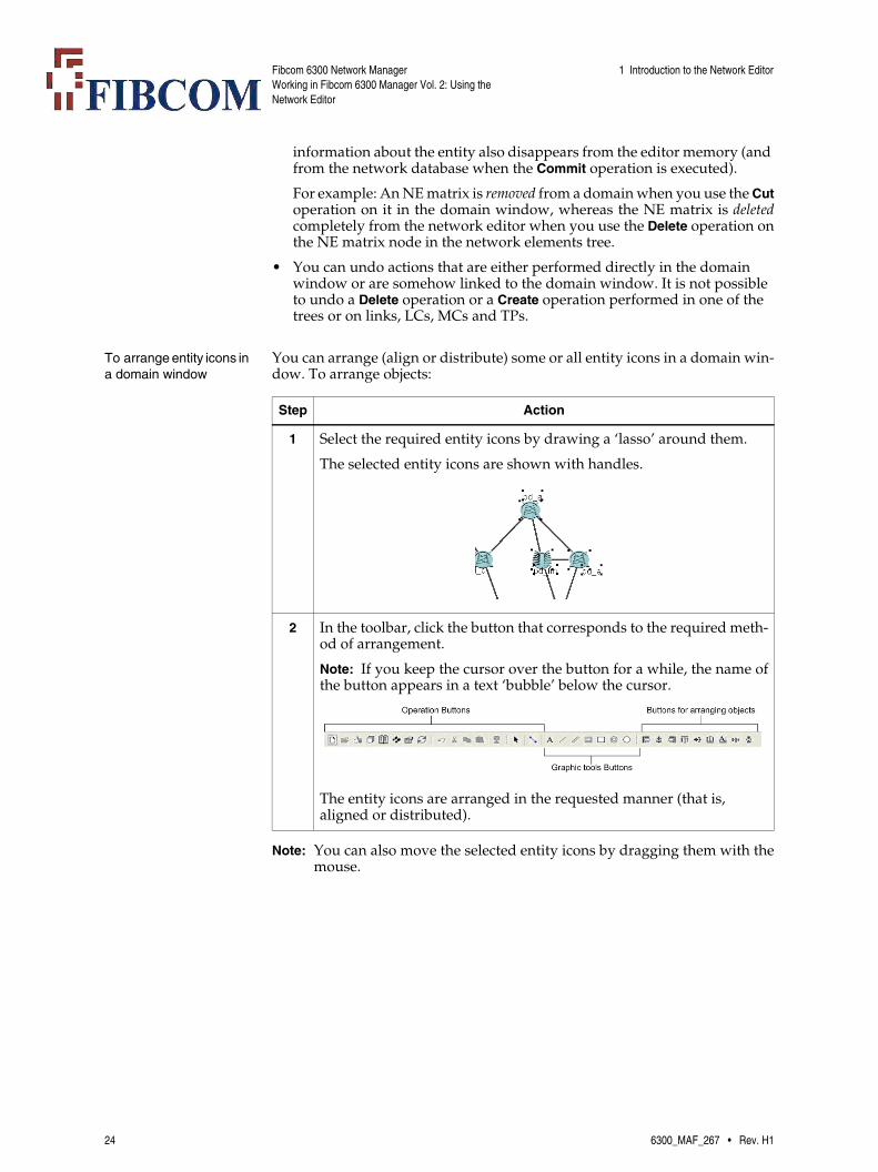
To arrange entity icons in a domain window
You can arrange (align or distribute) some or all entity icons in a domain win-dow. To arrange objects:
Note: You can also move the selected entity icons by dragging them with themouse.
Step Action
1 Select the required entity icons by drawing a ‘lasso’ around them.
The selected entity icons are shown with handles.
2 In the toolbar, click the button that corresponds to the required meth-od of arrangement.
Note: If you keep the cursor over the button for a while, the name ofthe button appears in a text ‘bubble’ below the cursor.
The entity icons are arranged in the requested manner (that is, aligned or distributed).
24 6300_MAF_267 • Rev. H1

Fibcom 6300 Network ManagerWorking in Fibcom 6300 Manager Vol. 2: Using the Network Editor
1 Introduction to the Network Editor
Configuring the network entities
You can configure the individual network entities in special property win-dows that are opened by double-clicking on the icon representing the networkentity in the domain window. The figure shows the various property win-dows corresponding to the various network entities.
6300_MAF_267 • Rev. H1 25

Fibcom 6300 Network ManagerWorking in Fibcom 6300 Manager Vol. 2: Using the Network Editor
1 Introduction to the Network Editor
In these windows you can do the following:
• For an NE matrix, you can specify a new NE class, a new NE name, a new NE matrix name, a new nick name, a new managing director and/or choose another icon.
• For a fibre matrix, you can insert CTPs and create MCs. You can also spec-ify a new nick name and choose another icon.
• For an external matrix, you can specify various types of interfaces for the external equipment that the external matrix represents. You can also spec-ify a new nick name and choose another icon.
• For a link, you can create and delete LCs or delete the link itself.
• For a domain, you can specify a new nick name and/or choose another icon.
Note: The Name field is non-editable in all windows except the NE Settingswindow.
26 6300_MAF_267 • Rev. H1

Fibcom 6300 Network ManagerWorking in Fibcom 6300 Manager Vol. 2: Using the Network Editor
1 Introduction to the Network Editor
To generate map files The changes that you make in the domains in the network editor are automat-ically transferred to the network layer views that can be shown in the NetworkManagement window. When you commit your changes, you can, however,also transfer the changes to the corresponding maps containing the views ofthe network.
To transfer the changes made in the network editor to the maps displayed inthe map window:
Note: You can configure the network editor to generate map files automati-cally, using the AlwaysGenerateMaps parameter.
Step Action
1 Select the menu entry File → Generate Maps or click the Generate maps button.
The Generate Map Files window appears.
The Generate Map Files window allows you to select which domains you wish to generate maps for. By default, only the names of those domains that have been opened are listed in the Generate list; but you can also add some or all of the not-opened domains.
2 Set up the Generate list in the Generate Map Files window to include the domains that you wish to generate maps for and click OK. (The domain names are transferred from one list to another by double-clicking on the name.)
The Generate Maps operation is added to the Commit operation. When the Commit operation is activated (see ‘To transfer (commit) your work in the network editor to the network database’ on page 29) and has been executed successfully, the maps are updated.
6300_MAF_267 • Rev. H1 27

Fibcom 6300 Network ManagerWorking in Fibcom 6300 Manager Vol. 2: Using the Network Editor
1 Introduction to the Network Editor
To close the Network Editor window
When you have finished your work in the network editor and have trans-ferred all of the changes to the network database, you leave the network editorby closing the Network Editor window.
Note: All changes that you have not transferred to the network database, willbe lost when you close the Network Editor window. That is, everythingis erased from the editor memory. A warning will therefore be dis-played if uncommitted changes exist when you try to close the NetworkEditor window.
To close the Network Editor window:
Step Action
1 In the Network Editor window, select the menu item File → Exit.
The Exit window showing the list of trails that have been removed and not re-established during your work in the network editor is dis-played.
See the description of the Exit window and the trail log in ‘1.6 The Trail Log and the Exit Window’ on page 34.
2 In the Exit window, click either Exit or on Delete and Exit (depending on whether you want to save the contents of the trail log or not).
Both the Exit window and the Network Editor window are closed.
28 6300_MAF_267 • Rev. H1

Fibcom 6300 Network ManagerWorking in Fibcom 6300 Manager Vol. 2: Using the Network Editor
1 Introduction to the Network Editor
1.4 Committing Your Work
To transfer (commit) your work in the network editor to the network database
While you are working in the network editor, all of your operations are storedin a Commit operation, but nothing is carried out until you actively commityour work.
This procedure describes how you transfer the work that you have made inthe network editor to the network database (that is, how you activate the Com-mit operation).
Step Action
1 Select the menu item File → Commit or click the Commit button.
The Commit window appears, showing the individual actions in the Commit operation.
See the description of the Commit window in ‘1.4.1 The Commit Win-dow’ on page 30.
2 Check that the contents of the Commit operation is correct and then click the Start button in the Commit window.
The changes are carried out in the network database.
6300_MAF_267 • Rev. H1 29
Fibcom 6300 Network ManagerWorking in Fibcom 6300 Manager Vol. 2: Using the Network Editor
1 Introduction to the Network Editor
1.4.1 The Commit Window
What the Commit window shows
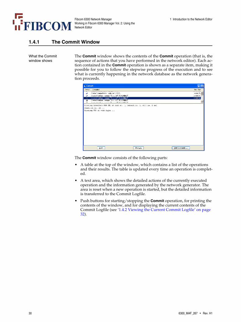
The Commit window shows the contents of the Commit operation (that is, thesequence of actions that you have performed in the network editor). Each ac-tion contained in the Commit operation is shown as a separate item, making itpossible for you to follow the stepwise progress of the execution and to seewhat is currently happening in the network database as the network genera-tion proceeds.
The Commit window consists of the following parts:
• A table at the top of the window, which contains a list of the operations and their results. The table is updated every time an operation is complet-ed.
• A text area, which shows the detailed actions of the currently executed operation and the information generated by the network generator. The area is reset when a new operation is started, but the detailed information is transferred to the Commit Logfile.
• Push buttons for starting/stopping the Commit operation, for printing the contents of the window, and for displaying the current contents of the Commit Logfile (see ‘1.4.2 Viewing the Current Commit Logfile’ on page 32).
30 6300_MAF_267 • Rev. H1
Fibcom 6300 Network ManagerWorking in Fibcom 6300 Manager Vol. 2: Using the Network Editor
1 Introduction to the Network Editor
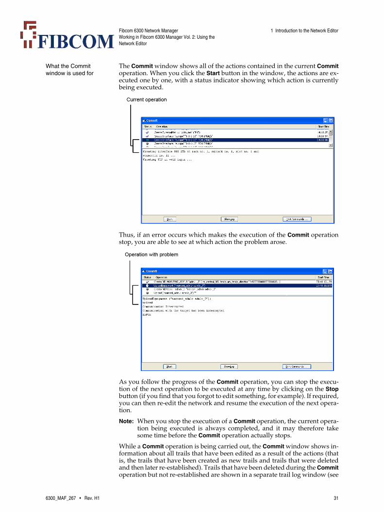
What the Commit window is used for
The Commit window shows all of the actions contained in the current Commitoperation. When you click the Start button in the window, the actions are ex-ecuted one by one, with a status indicator showing which action is currentlybeing executed.
Thus, if an error occurs which makes the execution of the Commit operationstop, you are able to see at which action the problem arose.
As you follow the progress of the Commit operation, you can stop the execu-tion of the next operation to be executed at any time by clicking on the Stopbutton (if you find that you forgot to edit something, for example). If required,you can then re-edit the network and resume the execution of the next opera-tion.
Note: When you stop the execution of a Commit operation, the current opera-tion being executed is always completed, and it may therefore takesome time before the Commit operation actually stops.
While a Commit operation is being carried out, the Commit window shows in-formation about all trails that have been edited as a result of the actions (thatis, the trails that have been created as new trails and trails that were deletedand then later re-established). Trails that have been deleted during the Commitoperation but not re-established are shown in a separate trail log window (see
6300_MAF_267 • Rev. H1 31
Fibcom 6300 Network ManagerWorking in Fibcom 6300 Manager Vol. 2: Using the Network Editor
1 Introduction to the Network Editor
‘1.6 The Trail Log and the Exit Window’ on page 34) when you are leaving thenetwork editor. You can then choose whether or not you want the trails to beplaced in the trail log for possible future network edition when you leave thenetwork editor (see ‘To close the Network Editor window’ on page 28).
1.4.2 Viewing the Current Commit Logfile
To view the commit logfile
While the Commit operation is being executed, the individual actions and theirresults are stored in the commit logfile. This operation describes how to viewthe current contents of the commit logfile.
Step Action
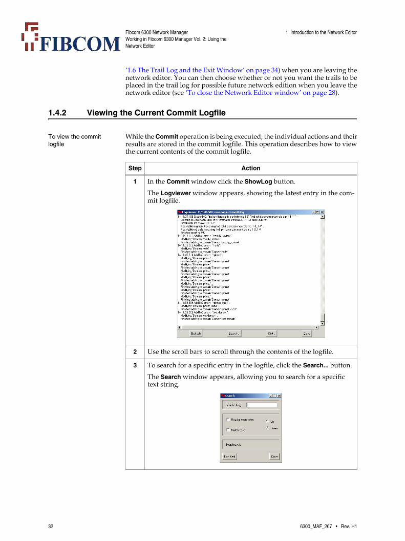
1 In the Commit window click the ShowLog button.
The Logviewer window appears, showing the latest entry in the com-mit logfile.
2 Use the scroll bars to scroll through the contents of the logfile.
3 To search for a specific entry in the logfile, click the Search... button.
The Search window appears, allowing you to search for a specific text string.
32 6300_MAF_267 • Rev. H1

Fibcom 6300 Network ManagerWorking in Fibcom 6300 Manager Vol. 2: Using the Network Editor
1 Introduction to the Network Editor
To view the details of a specific operation
The Commit window only shows the details of the operation which is current-ly being executed. The details of the previous operations are, however, storedin the Commit Logfile. This procedure describes how to view the details of aspecific, previously executed operation.
1.5 If a Problem Occurs during Execution of a Commit Operation
Locating and correcting any problems
If any problem occurs during the execution of a Commit operation, the net-work editor stops the operation. In the Commit window you can see the prob-lem and at which action the problem arose (see ‘1.4.1 The Commit Window’on page 30).
If required, you can fix the problem in NWLMS and then recommit the re-maining part of the Commit operation. Or you can recommit the remainingpart of the operation without any changes in NWLMS if the problem was, forexample, a data communication problem (that is, a problem not related toNWLMS) which now has been fixed.
Note: You can also cancel the remaining part of the Commit operation, if re-quired, by editing the network editor.
The state of the network database
When a Commit operation is stopped during execution, those actions that havealready been carried out are not undone. That is, the network database is notbrought back to its state from before you started the Commit operation.
Step Action
1 In the Commit window double-click on the entry for the relevant op-eration in the table.
The Logviewer window appears, showing the Commit Logfile entry for the selected operation.
6300_MAF_267 • Rev. H1 33
Fibcom 6300 Network ManagerWorking in Fibcom 6300 Manager Vol. 2: Using the Network Editor
1 Introduction to the Network Editor
1.6 The Trail Log and the Exit Window
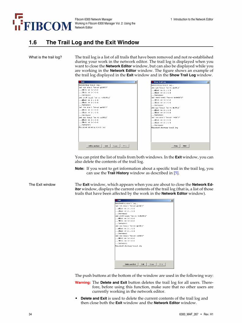
What is the trail log? The trail log is a list of all trails that have been removed and not re-establishedduring your work in the network editor. The trail log is displayed when youwant to close the Network Editor window, but can also be displayed while youare working in the Network Editor window. The figure shows an example ofthe trail log displayed in the Exit window and in the Show Trail Log window.
You can print the list of trails from both windows. In the Exit window, you canalso delete the contents of the trail log.
Note: If you want to get information about a specific trail in the trail log, youcan use the Trail History window as described in [5].
The Exit window The Exit window, which appears when you are about to close the Network Ed-itor window, displays the current contents of the trail log (that is, a list of thosetrails that have been affected by the work in the Network Editor window).
The push buttons at the bottom of the window are used in the following way:
Warning: The Delete and Exit button deletes the trail log for all users. There-fore, before using this function, make sure that no other users arecurrently working in the network editor.
• Delete and Exit is used to delete the current contents of the trail log and then close both the Exit window and the Network Editor window.
34 6300_MAF_267 • Rev. H1

Fibcom 6300 Network ManagerWorking in Fibcom 6300 Manager Vol. 2: Using the Network Editor
1 Introduction to the Network Editor
• Exit is used to close both the Exit window and the Network Editor window without changing the contents of the trail log.
• Cancel is used to close the Exit window without closing the Network Editor window. The contents of the trail log are not changed.
• Print is used to print the contents of the trail log on your default printer.
Note: If you want to get information about a specific trail in the trail log, youcan use the Trail History window as described in [5].
To display the trail log during the work
To see the current contents of the trail log while you are still working in thenetwork editor:
Step Action
1 In the Network Editor window, use one of the following methods:
• Select the menu item File → Show Trail Log.
• Click the Show trail log button.
The Show Trail Log window appears.
The window contains a list of trails that have been deleted but not re-established in NWLMS during previous Commit operations. The Print button allows you to print the list.
Note: If you want to get information about a specific trail in the traillog, you can use the Trail History window as described in [5].
6300_MAF_267 • Rev. H1 35

Fibcom 6300 Network ManagerWorking in Fibcom 6300 Manager Vol. 2: Using the Network Editor
1 Introduction to the Network Editor
36 6300_MAF_267 • Rev. H1

Fibcom 6300 Network ManagerWorking in Fibcom 6300 Manager Vol. 2: Using the Network Editor
2 The Basic Procedures for Editing a Network
2 The Basic Procedures for Editing a Network
Types of basic procedures
The basic procedures that you can perform with the network editor to edit anetwork are split up into the following groups:
• Adding, changing and deleting network entities in the network:
• ‘2.1 Adding a New NE to the Network’ on page 37
• ‘2.2 Adding a New ETEX NE to the Network’ on page 40
• ‘2.3 Adding a New NE Matrix to the Network’ on page 41
• ‘2.4 Adding a New External Matrix to the Network’ on page 42
• ‘2.5 Adding a New Fibre Matrix to the Network’ on page 67
• ‘2.6 Automatic Registration of 7100 NEs’ on page 73
• ‘2.7 Adding a TeMIP Object to a Domain’ on page 74
• ‘2.8 Inserting a Link between Two Network Entities’ on page 75
• ‘2.9 Changing NE Settings’ on page 78
• ‘2.10 Deleting Network Entities from the Network’ on page 80
• Uploading cross connection and TP information from the real network to the database (‘2.11 Uploading Information from the Network’ on page 83)
• ‘2.12 Establishing Trails from the Network’ on page 87
• Creating domains and re-organizing the domain structure of the network (‘2.13 Creating and Re-organizing Domains’ on page 88).
Actual work situations (scenarios) that can be carried out by combining theseprocedures are described in ‘3 Examples of Work Scenarios’ on page 95.
2.1 Adding a New NE to the Network
To add a new NE to the list of NEs
When you create a new NE in the network editor, information about the phys-ical equipment is automatically uploaded. To create a new NE:
Step Action
1 Select the general node for the relevant NE type in the network ele-ments tree.
6300_MAF_267 • Rev. H1 37

Fibcom 6300 Network ManagerWorking in Fibcom 6300 Manager Vol. 2: Using the Network Editor
2 The Basic Procedures for Editing a Network
2 Open the pop-up menu and select the menu item New NE.
The New NE window appears.
3 Select the required NE type from the NE Class: drop-down list.
Note: If the NE Class supports IP DCN management, the Element set-up group box contains fields for both an NSAP address and an IP ad-dress.
4 Type a name for the NE in the NE Name: field.
Note: The name appears simultaneously in the NEMatrix Name: field.
5 If required, select the NEMatrix Name: check box and type a special name for the NE matrix in the NEMatrix Name: field.
6 Do one of the following:
• If the NE does not support IP DCN management, go to Step 7.
• If the NE supports IP DCN management, go to Step 8.
7 Enter the NSAP address of the NE in the NSAPAddress: selection line.
You can either type the numbers directly or open the drop-down lists to select existing numbers and edit them.
For more information about NSAP addresses, see ‘Structure of the NSAP address assigned during production’ on page 39.
Step Action
38 6300_MAF_267 • Rev. H1

Fibcom 6300 Network ManagerWorking in Fibcom 6300 Manager Vol. 2: Using the Network Editor
2 The Basic Procedures for Editing a Network
Note: You can also create a new NE via the pop-up menu in a domain win-dow.
Structure of the NSAP address assigned during production
NEs are assigned the default NSAP address 490001<System/Node ID>01 dur-ing production.
Note: The Area Address 490001 and the Selector Field part 01 of the NSAP ad-dress are always the same, only the System/Node ID part is different:
Where to find the unique Ethernet address of an NE
The central management module for the NE has a label attached to its side. Onthis label you can read the unique Ethernet address given to the module dur-ing its production. The Ethernet address is printed after the letters “EA=”(which stands for Ethernet address).
8 Type in the type of address the NE requires. You can enter one or both of the following addresses:
• If you want to manage the NE using OSI DCN, select the NSAP Address radio button and enter the NSAP address of the NE in the NSAP Address: fields.
You can either type the numbers directly or open the drop-downlists to select existing numbers and edit them.
• If you want to manage the NE using IP DCN, select the IP address radio button and enter the IP address of the NE in the IP Address: fields.
Note: If you want to manage the NE using IP DCN via the embed-ded communication channels (ECCs), then you must also enter theNSAP address for the NE in the NSAP Address: fields.
For more information about NSAP addresses, see ‘Structure of the NSAP address assigned during production’ on page 39.
9 Click Apply or OK.
An NE node with the specified name appears under the NE type node in the network elements tree.
Step Action
Area Address(from 1 - 13 bytes
in length)
System/Node ID(always 6 bytes in length)
Selector Field (SEL) (always of 1
byte in length)
49 00 01 Fibcom use the NE’s Ethernet Address as the Sys-tem/Node ID of the NE. Each master module is given its own unique Ethernet address during production (see ‘Where to find the unique Ether-net address of an NE’ on page 39).
01
Example:
49 00 01 00 A0 82 10 01 0A 01
The first three bytes of the System/Node ID are unique to all Fib-com equipment.
The following three bytes are unique to the specific piece of equip-ment produced by Fib-com
All Fibcom equipment, must be assigned an SEL = 01.
6300_MAF_267 • Rev. H1 39
Fibcom 6300 Network ManagerWorking in Fibcom 6300 Manager Vol. 2: Using the Network Editor
2 The Basic Procedures for Editing a Network
2.2 Adding a New ETEX NE to the Network
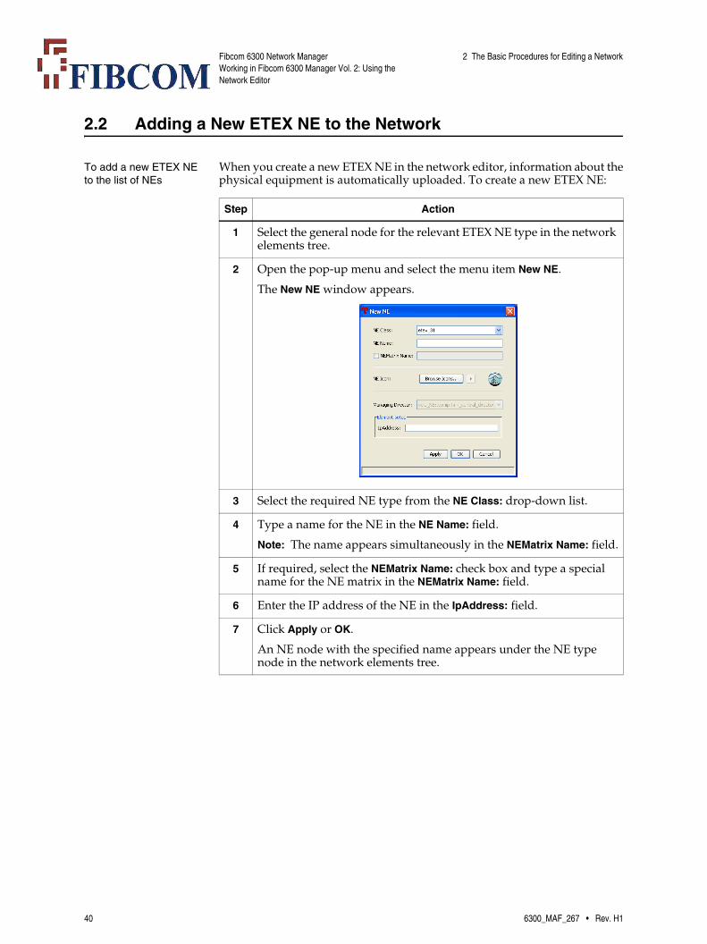
To add a new ETEX NE to the list of NEs
When you create a new ETEX NE in the network editor, information about thephysical equipment is automatically uploaded. To create a new ETEX NE:
Step Action
1 Select the general node for the relevant ETEX NE type in the network elements tree.
2 Open the pop-up menu and select the menu item New NE.
The New NE window appears.
3 Select the required NE type from the NE Class: drop-down list.
4 Type a name for the NE in the NE Name: field.
Note: The name appears simultaneously in the NEMatrix Name: field.
5 If required, select the NEMatrix Name: check box and type a special name for the NE matrix in the NEMatrix Name: field.
6 Enter the IP address of the NE in the IpAddress: field.
7 Click Apply or OK.
An NE node with the specified name appears under the NE type node in the network elements tree.
40 6300_MAF_267 • Rev. H1

Fibcom 6300 Network ManagerWorking in Fibcom 6300 Manager Vol. 2: Using the Network Editor
2 The Basic Procedures for Editing a Network
2.3 Adding a New NE Matrix to the Network
Prerequisite Before you can add an NE matrix in the network editor, the corresponding NEmust already be installed in the real network. It must also be created in Fibcom6300 manager, as described in ‘To add a new NE to the list of NEs’ on page 37..
To add a new NE matrix to the domain
Nodes representing all of the NEs that have been registered in Fibcom 6300manager are shown in the network elements tree. This procedure describeshow you create and place an NE matrix representing one of these NEs in a do-main window.
Step Action
1 Open the relevant domain in the Network Editor window (see ‘To open an existing domain’ on page 23).
2 Select the relevant NE node in the network elements tree (under the NE type node) and select the menu item Create NEMatrix in the pop-up menu.
An NE matrix icon appears under the NE node.
3 Select the NE matrix icon in the network elements tree and drag it over onto the domain window to its position in the domain.
The NE matrix icon appears in the domain window.
6300_MAF_267 • Rev. H1 41

Fibcom 6300 Network ManagerWorking in Fibcom 6300 Manager Vol. 2: Using the Network Editor
2 The Basic Procedures for Editing a Network
2.4 Adding a New External Matrix to the Network
Overview An external matrix can be considered as a “black box”, where only the differ-ent interfaces of the external matrix to which the managed network can beconnected, as well as the internal connections between some of the interfaces,are stored in Fibcom 6300 manager. The external matrix can thus representone or more NEs collected in a subnetwork which is not managed from Fib-com 6300 manager. The process of adding an external matrix to a network con-sists of the stages described in the table.
Note: We use three examples of external matrix configurations in the descrip-tions of the basic procedures, in order to make the configurations moresimple. The examples are introduced in ‘2.4.2 The Three Examples’ onpage 43.
2.4.1 Flexibility and Inflexibility
The need for inflexible external matrices
External matrices can be used to ‘simulate’ an NE or a whole sub-network ofNEs which cannot be managed from Fibcom 6300 manager.
If the NEs in the sub-network do not belong to the operator who is using Fib-com 6300 manager, but belong to a network which is managed by another op-erator, the connection simulated by the external matrix could be a leased line.Such a leased line cannot be set up arbitrarily nor can it be removed arbitrari-ly. The leased line requires special agreements between the two operators,where one important issue that they must agree upon is the ports (TPs) thatthe connection (leased line) must be set up between.
When handling leased lines, it is essential that there are no free resources (LCsor CTPs) which can be used freely to set up any other MC in the external ma-trix when you use Trail Setup with automatic routing. By making the externalmatrix inflexible, you ensure that it contains only the TPs and MCs which youhave specified.
4 If you want to change one or more of the settings of the NE or the NE matrix icon, double-click the NE matrix icon.
The NE Settings window appears.
See ‘2.9 Changing NE Settings’ on page 78 for an example of the pro-cedure.
Step Action
Stage Description
1 Deciding what the interface type of each interface in the external equipment (represented by the external matrix) is and how it should be represented in the external matrix.
2 Creating the external matrix icon and placing it in the domain.
3 Creating the required interfaces in the external matrix.
4 Creating the necessary inflexible MCs to reflect the signals that are always carried through the external matrix.
42 6300_MAF_267 • Rev. H1

Fibcom 6300 Network ManagerWorking in Fibcom 6300 Manager Vol. 2: Using the Network Editor
2 The Basic Procedures for Editing a Network
New external matrices When you create a new external matrix, the flexibility/inflexibility of the var-ious layers will as default be:
• Inflexible layers: Physical, OMS, OCH, RS and MS
• Flexible layers: Data, VC-4, VC-3 and VC-12.
This means that external matrices at the physical, OMS, OCH, RS and MS lay-ers initially will contain TPs connected by MCs, whereas external matrices atthe Data, VC-4, VC-3 and VC-12 layers will contain only TPs or be empty.
2.4.2 The Three Examples
The configuration of example 1
Our first example for an external matrix is a configuration that corresponds toan AC1_30 (SDH and PDH ports). The figure shows this configuration.
The configuration of example 2
Our second example for an external matrix is a configuration that correspondsto a WDM multiplexer with 4 channels. That is:
• 4 tributary ports at 1-2-4-1, 1-2-4-2, 1-2-4-3 and 1-2-4-4
• 1 aggregate port 1-2-3-4 with 4 channels.
The configuration of example 3
Our third example for an external matrix is a configuration that correspondsto a VCG and ETH ports. That is:
• SDH VC4 submux with signal structure (1x TU3 -21x VC12 -1x TU3) at 1-1-1-1 and SDH VC4 (not-submux-VCG) at 1-1-1-2.
• 3 VCG ports, VCG(VC3) at 1-1-2-1, VCG(VC12) at 1-1-2-2 and VCG(VC4) at 1-1-2-3. Where VC3, VC12 and VC4 in the brackets are indicating signal type of the corresponding VCGs.
• 1 ETH Ten Base port at 1-1-3-1
6300_MAF_267 • Rev. H1 43

Fibcom 6300 Network ManagerWorking in Fibcom 6300 Manager Vol. 2: Using the Network Editor
2 The Basic Procedures for Editing a Network
2.4.3 Deciding the Configuration of an External Matrix
Interface types in an external matrix
The following interface types are available:
Note: Further specification is required for the following interface types:
• SDH STM-n Mux: The STM-n level (1, 4, 16 or 64) must be specified. The amount of CTPs created at the VC-4 layer depends on the STM-n level. STM-1 is the default.
• VC4 submux: The actual signal structure must be specified either when creating the VC4 submux SDH interface or when setting up the trail (see 9). The relevant number of VC-3/VC-12 CTPs are created when the signal structure is specified during creation of VC4 submux interface or when the trail is put into service. The VC-3/VC-12 CTPs can be member of VCG, only when the created VC4 submux is specified as concatenated type.
Interface Type Description
SDH STM-n Reg An STM-n port on an SDH regenerator.
STM-n Mux An STM-n port on an 4/4 or 4/1 SDH NE. See also the note below the table.
VC4 submux A VC-4 TTP which serves VC-12 and/or VC-3 CTPs. That is, a VC-4 TTP with SDH signal struc-ture (sub-multiplexed). See also the note below the table.
WDM Amplifier One of two ports on a WDM amplifier.
Mux Aggr An aggregate port on a WDM multiplexer. See also the note below the table.
Mux Trib A tributary SDH port on a WDM multiplexer.
PDH 140Mbit A 140 Mbit/s port.
34Mbit/45Mbit A 34 Mbit/s or 45 Mbit/s port.
2Mbit A 2 Mbit/s port.
VCG VCG(VC3) A VCG port with VC3s as its member.
VCG(VC12) A VCG port with VC12s as its member.
VCG(VC4) A VCG port with VC4s as its member..
ETH Ethernet Ten Base A Ten Base Ethernet port.
Ethernet Hundred Base
A Hundred Base Ethernet port.
Ethernet One Giga Base
A One Giga Base Ethernet port.
Ethernet Ten Giga Base
A Ten Giga Base Ethernet port.
44 6300_MAF_267 • Rev. H1
Fibcom 6300 Network ManagerWorking in Fibcom 6300 Manager Vol. 2: Using the Network Editor
2 The Basic Procedures for Editing a Network
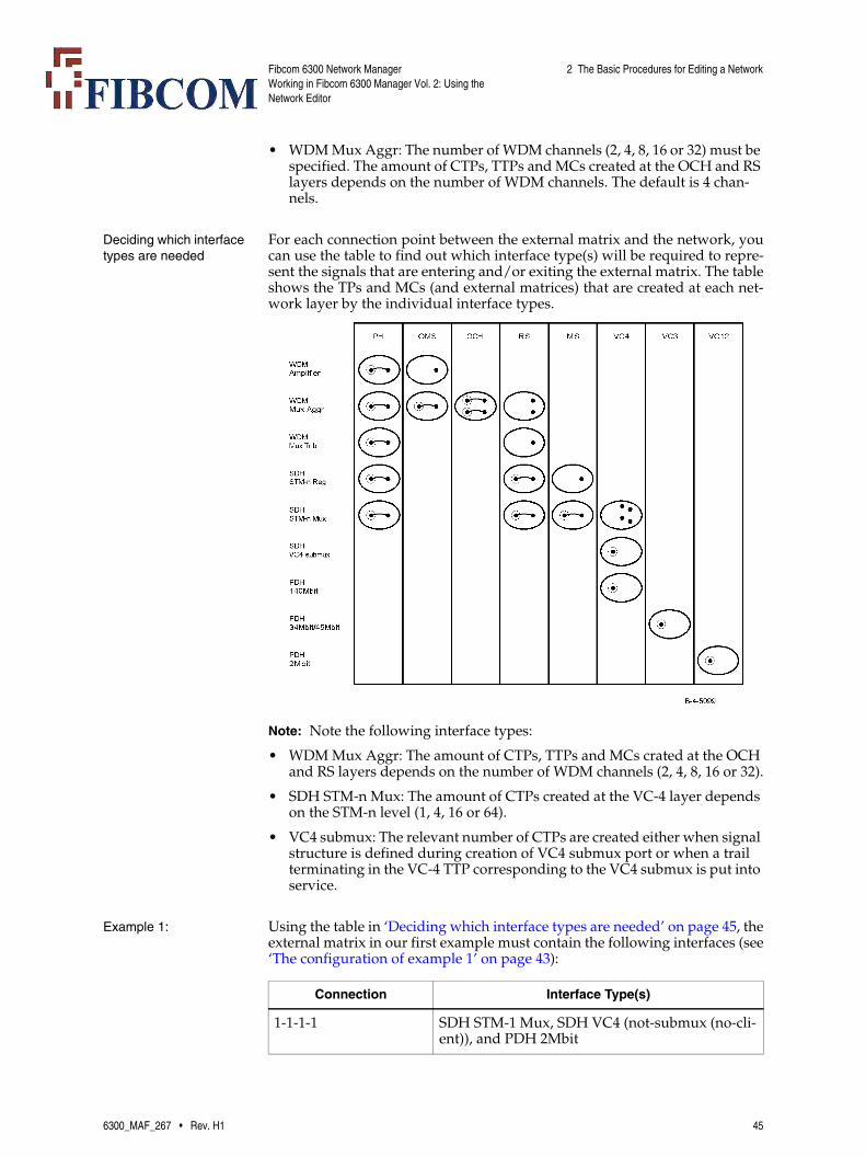
• WDM Mux Aggr: The number of WDM channels (2, 4, 8, 16 or 32) must be specified. The amount of CTPs, TTPs and MCs created at the OCH and RS layers depends on the number of WDM channels. The default is 4 chan-nels.
Deciding which interface types are needed
For each connection point between the external matrix and the network, youcan use the table to find out which interface type(s) will be required to repre-sent the signals that are entering and/or exiting the external matrix. The tableshows the TPs and MCs (and external matrices) that are created at each net-work layer by the individual interface types.
Note: Note the following interface types:
• WDM Mux Aggr: The amount of CTPs, TTPs and MCs crated at the OCH and RS layers depends on the number of WDM channels (2, 4, 8, 16 or 32).
• SDH STM-n Mux: The amount of CTPs created at the VC-4 layer depends on the STM-n level (1, 4, 16 or 64).
• VC4 submux: The relevant number of CTPs are created either when signal structure is defined during creation of VC4 submux port or when a trail terminating in the VC-4 TTP corresponding to the VC4 submux is put into service.
Example 1: Using the table in ‘Deciding which interface types are needed’ on page 45, theexternal matrix in our first example must contain the following interfaces (see‘The configuration of example 1’ on page 43):
Connection Interface Type(s)
1-1-1-1 SDH STM-1 Mux, SDH VC4 (not-submux (no-cli-ent)), and PDH 2Mbit
6300_MAF_267 • Rev. H1 45

Fibcom 6300 Network ManagerWorking in Fibcom 6300 Manager Vol. 2: Using the Network Editor
2 The Basic Procedures for Editing a Network
Example 2: Using the table in ‘Deciding which interface types are needed’ on page 45, theexternal matrix in our second example must contain the following interfaces(see ‘The configuration of example 2’ on page 43):
Example 3: Using the table in ‘Deciding which interface types are needed’ on page 45 theexternal matrix in our third example must contain the following interfaces(see ‘The configuration of example 3’ on page 43):
Note: The VC3, VC12 and VC4 in the brackets with VCGs are indicating sig-nal type of the corresponding VCG.
2.4.4 Creating an External Matrix Icon
To add an external matrix to the domain
This procedure describes how you create and place a new external matrix iconin a domain window.
1-1-1-2 SDH STM-1 Mux, SDH VC4 (not-submux (no-cli-ent)), and PDH 2Mbit
1-1-1-1 to 1-1-1-21 PDH 2Mbit
1-1-2-1 to 1-1-2-21 PDH 2Mbit
1-1-3-1 to 1-1-3-3 PDH 34Mbit
Connection Interface Type(s)
Connection Interface Type(s)
1-2-3-4 WDM Mux Aggr (4 channels)
1-2-4-1 to 1-2-4-4 WDM Mux Trib
Connection Interface Type(s)
1-1-1-1 SDH VC4 submux with signal type (1x TU3 -21x VC12 -1x TU3)
1-1-1-2 SDH VC4 (not-submux-VCG)
1-1-2-1 VCG (VC3)
1-1-2-2 VCG (VC12)
1-1-2-3 VCG (VC4)
1-1-3-1 ETH TEN BASE
Step Action
1 Open the relevant domain in the Network Editor window (see ‘To open an existing domain’ on page 23).
46 6300_MAF_267 • Rev. H1

Fibcom 6300 Network ManagerWorking in Fibcom 6300 Manager Vol. 2: Using the Network Editor
2 The Basic Procedures for Editing a Network
2 Select the general External Matrices node in the network objects tree and select the menu item New → External Matrix in the pop-up menu.
An Input window appears, prompting you for a name for the new ex-ternal matrix.
3 Type the required name in the field and click OK.
A new external matrix node with the specified appears in the net-work objects tree, at the bottom of the list under the general external matrices node.
4 Select the external matrix node in the network objects tree and drag it over onto the domain window and to its position in the domain.
The external matrix icon appears in the domain window.
5 Configure the ‘contents’ of the external matrix, as described in ‘To create SDH and PDH interfaces’ on page 48.
Step Action
6300_MAF_267 • Rev. H1 47

Fibcom 6300 Network ManagerWorking in Fibcom 6300 Manager Vol. 2: Using the Network Editor
2 The Basic Procedures for Editing a Network
2.4.5 Specifying the Interface Structure of an External Matrix
To create SDH and PDH interfaces
This procedure describes how to create the SDH and PDH interfaces that arerequired in the external matrix of our first example according to ‘Example 1:’on page 45.
Step Action
1 Double-click on the external matrix icon in the domain.
The ExternalMatrix window appears.
The window consists of two areas:
• The identification area, which allows you to change the nick name of the icon as well as select another type of icon.
• The structure area, in which you create the interface structure of the external matrix.
Note: The structure area of the ExternalMatrix window for a new ex-ternal matrix contains only the general external matrix node.
48 6300_MAF_267 • Rev. H1
Fibcom 6300 Network ManagerWorking in Fibcom 6300 Manager Vol. 2: Using the Network Editor
2 The Basic Procedures for Editing a Network
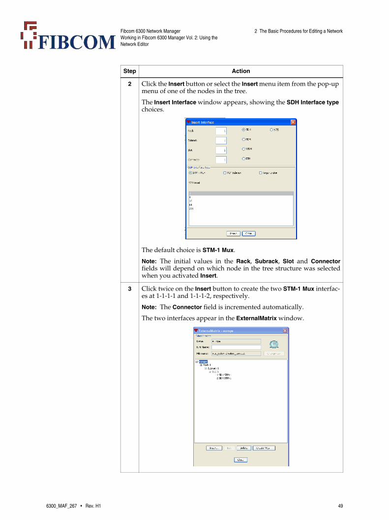
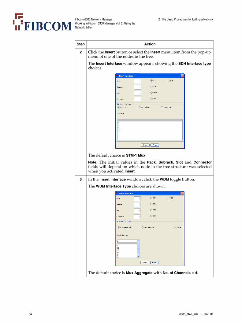
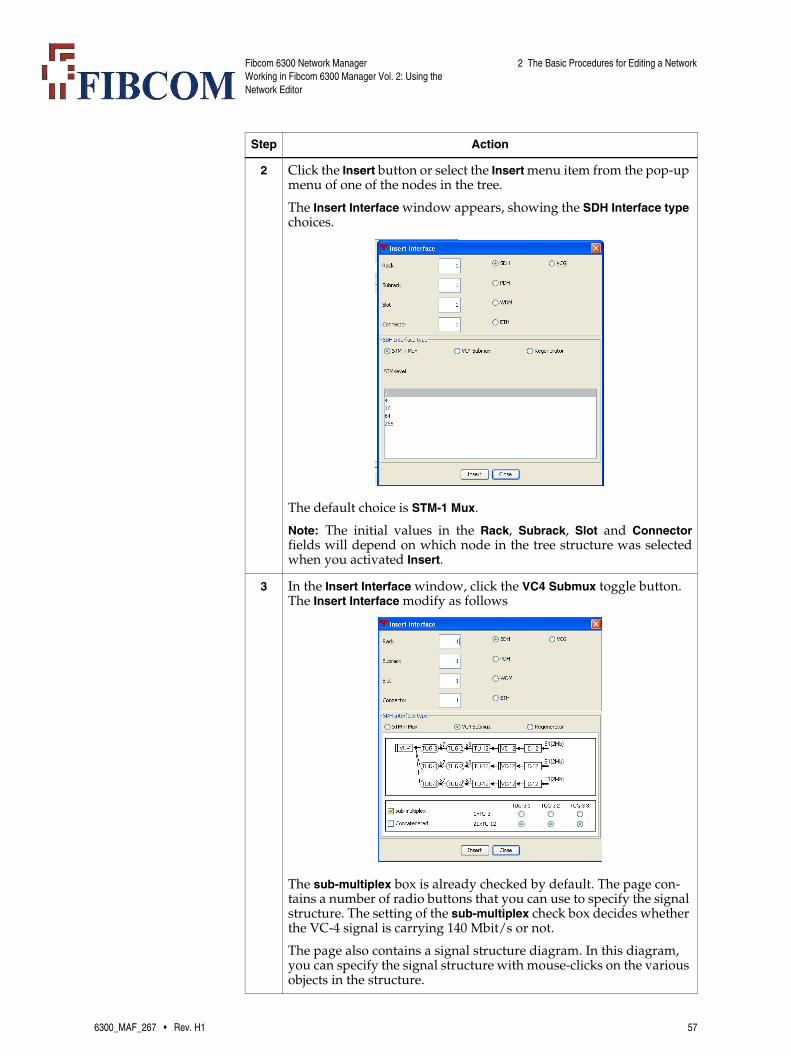
2 Click the Insert button or select the Insert menu item from the pop-up menu of one of the nodes in the tree.
The Insert Interface window appears, showing the SDH Interface type choices.
The default choice is STM-1 Mux.
Note: The initial values in the Rack, Subrack, Slot and Connectorfields will depend on which node in the tree structure was selectedwhen you activated Insert.
3 Click twice on the Insert button to create the two STM-1 Mux interfac-es at 1-1-1-1 and 1-1-1-2, respectively.
Note: The Connector field is incremented automatically.
The two interfaces appear in the ExternalMatrix window.
Step Action
6300_MAF_267 • Rev. H1 49

Fibcom 6300 Network ManagerWorking in Fibcom 6300 Manager Vol. 2: Using the Network Editor
2 The Basic Procedures for Editing a Network
4 In the Insert Interface window, click the VC4 Submux toggle button. The Insert Interface window will modify as below
The sub-multiplex option is already checked by default. The page contains a number of radio buttons that you can use to specify the signal structure. The setting of the sub-multiplex check box decides whether the VC-4 signal is carrying 140 Mbit/s or not.
a) Set Rack-Subrack-Slot-Connector to 1-1-1-1.
b) Uncheck the sub-multiplex option. The Insert Interface window will modify as below
c) Click No Client toggel button.
d) In the Insert Interface window, clickt Insert button. The VC4 (not-submux (no-client)) interfaces appears at 1-1-1-1in the ExternalMa-trix window.Follow the same steps as mentioned for creating VC4 (not-submux (no-client)) interface at 1-1-1-1, to create VC4 (not-submux (no-client)) interface at 1-1-1-2. Two VC4 (not-submux (no-client)) interfaces appear at 1-1-1-1 and 1-1-1-2 in the External-Matrix window.
Step Action
50 6300_MAF_267 • Rev. H1

Fibcom 6300 Network ManagerWorking in Fibcom 6300 Manager Vol. 2: Using the Network Editor
2 The Basic Procedures for Editing a Network
5 In the Insert Interface window, click the PDH toggle button.
The PDH Interface Type choices are shown.
The default choice is 2 Mbit/s.
6 Click the 34 Mbit/s toggle button and create interfaces at 1-1-3-1 to 1-1-3-3.
The 3 interfaces appear in the ExternalMatrix window.
7 In the Insert Interface window, click the 2 Mbit/s toggle button and create 2x21 PDH 2 Mbit/s interfaces at 1-1-1-1 to 1-1-1-21 and 1-1-2-1 to 1-1-2-21.
The 42 interfaces appear in the ExternalMatrix window.
Note: If the number of interfaces in the external matrix exceeds whatcan be shown in the ExternalMatrix window, a scroll bar appears onthe right side of the window.
Step Action
6300_MAF_267 • Rev. H1 51

Fibcom 6300 Network ManagerWorking in Fibcom 6300 Manager Vol. 2: Using the Network Editor
2 The Basic Procedures for Editing a Network
When the Commit operation is executed, TTPs, CTPs and MCs are created forthe external matrix at the relevant layers, as shown in ‘A Matrix Views of theExternal Matrix Examples’ on page 113.
Note: In the ExternalMatrix window, Delete button can be used to remove un-wanted interface created for external matrix. To remove unwanted in-terface, select the interface and click the Delete button. The selected in-terface removes from ExternalMatrix window.
Note: No CTPs are created at the VC-3 and VC-12 layers. They will be createdwhen the VC-4 trail terminating in the VC4 submux TTP is put into ser-vice.
8 In the Insert Interface window, click Close.
The Insert Interface window is closed.
Step Action
52 6300_MAF_267 • Rev. H1

Fibcom 6300 Network ManagerWorking in Fibcom 6300 Manager Vol. 2: Using the Network Editor
2 The Basic Procedures for Editing a Network
To create WDM interfaces
This procedure describes how to create the WDM interfaces that are requiredin the external matrix of our second example according to ‘Example 2:’ onpage 46.
Step Action
1 Double-click on the external matrix icon in the domain.
The ExternalMatrix window appears.
The window consists of two areas:
• The identification area, which allows you to change the nick name of the icon as well as select another type of icon.
• The structure area, in which you create the interface structure of the external matrix.
Note: The structure area of the ExternalMatrix window for a new ex-ternal matrix contains only the general external matrix node.
6300_MAF_267 • Rev. H1 53
Fibcom 6300 Network ManagerWorking in Fibcom 6300 Manager Vol. 2: Using the Network Editor
2 The Basic Procedures for Editing a Network
2 Click the Insert button or select the Insert menu item from the pop-up menu of one of the nodes in the tree.
The Insert Interface window appears, showing the SDH Interface type choices.
The default choice is STM-1 Mux.
Note: The initial values in the Rack, Subrack, Slot and Connectorfields will depend on which node in the tree structure was selectedwhen you activated Insert.
3 In the Insert Interface window, click the WDM toggle button.
The WDM Interface Type choices are shown.
The default choice is Mux Aggregate with No. of Channels = 4.
Step Action
54 6300_MAF_267 • Rev. H1

Fibcom 6300 Network ManagerWorking in Fibcom 6300 Manager Vol. 2: Using the Network Editor
2 The Basic Procedures for Editing a Network
4 Set Rack-Subrack-Slot-Connector to 1-2-3-4 and click Insert.
The 4-channelled WDM Mux Aggr interface appears in the ExternalMa-trix window.
5 In the Insert Interface window, click the Mux Tributary toggle button and insert interfaces at 1-2-4-1 to 1-2-4-4.
The 4 interfaces appear in the ExternalMatrix window.ü
6 In the Insert Interface window, click Close.
The Insert Interface window is closed.
7 Create the MCs in the external matrix, as described in ‘To create MCs in an external matrix’ on page 63.
Step Action
6300_MAF_267 • Rev. H1 55

Fibcom 6300 Network ManagerWorking in Fibcom 6300 Manager Vol. 2: Using the Network Editor
2 The Basic Procedures for Editing a Network
Note: In the ExternalMatrix window, Delete button can be used to remove un-wanted interface created for external matrix. To remove unwanted in-terface, select the interface and click the Delete button. The selected in-terface removes from ExternalMatrix window.
To create the VCG and ETH interfaces
This procedure describes how to create the VCG and ETH interfaces that arerequired in the external matrix of our third example according to ‘Example 3:’on page 46.
Step Action
1 Double-click on the external matrix icon in the domain.
The ExternalMatrix window appears.
The window consists of two areas:
• The identification area, which allows you to change the nick name of the icon as well as select another type of icon.
• The structure area, in which you create the interface structure of the external matrix.
Note: The structure area of the ExternalMatrix window for a new ex-ternal matrix contains only the general external matrix node.
56 6300_MAF_267 • Rev. H1
Fibcom 6300 Network ManagerWorking in Fibcom 6300 Manager Vol. 2: Using the Network Editor
2 The Basic Procedures for Editing a Network
2 Click the Insert button or select the Insert menu item from the pop-up menu of one of the nodes in the tree.
The Insert Interface window appears, showing the SDH Interface type choices.
The default choice is STM-1 Mux.
Note: The initial values in the Rack, Subrack, Slot and Connectorfields will depend on which node in the tree structure was selectedwhen you activated Insert.
3 In the Insert Interface window, click the VC4 Submux toggle button. The Insert Interface modify as follows
The sub-multiplex box is already checked by default. The page con-tains a number of radio buttons that you can use to specify the signal structure. The setting of the sub-multiplex check box decides whether the VC-4 signal is carrying 140 Mbit/s or not.
The page also contains a signal structure diagram. In this diagram, you can specify the signal structure with mouse-clicks on the various objects in the structure.
Step Action
6300_MAF_267 • Rev. H1 57
Fibcom 6300 Network ManagerWorking in Fibcom 6300 Manager Vol. 2: Using the Network Editor
2 The Basic Procedures for Editing a Network
4 To create VC4 (submux) interface, leave the sub-multiplex option checked.
a) Set Rack-Subrack-Slot-Connector to 1-1-1-1.
b) Leave the sub-multiplex option checked.
c) Change the signal structure according to ‘Example 3:’ on page 46, using one of the following methods
• Click on the relevant objects in the signal structure diagram with the primary mouse button to change the diagram to the required signal structure.
• Use the available TU-3/TU-12 radio buttons to select the signal struture.
Note: See ‘The settings for the sub-multiplexed VC-4 signal struc-tures’ on page 62 for a description of how to set the radio buttons.
5 Check the Concatenated option and click the Insert button. A VC4(1X TU3- 21X TU21- 1X TU3) interface appears at 1-1-1-1 in the ExternalMa-trix widow. The signal ID of VC4 interface appears in bracket adja-cent toVC4.
Note: The Concatenated option must be checked, if you want TU-3and TU-12 CTPs of VC4 submux interface to be member of VCG.
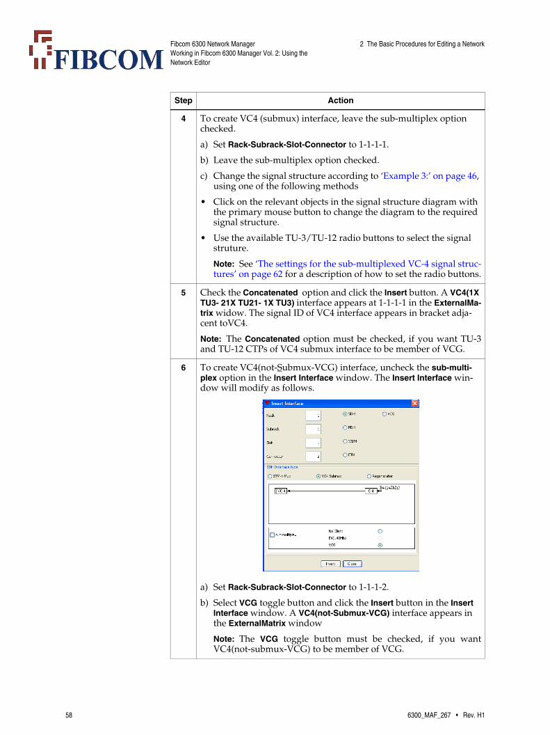
6 To create VC4(not-Submux-VCG) interface, uncheck the sub-multi-plex option in the Insert Interface window. The Insert Interface win-dow will modify as follows.
a) Set Rack-Subrack-Slot-Connector to 1-1-1-2.
b) Select VCG toggle button and click the Insert button in the Insert Interface window. A VC4(not-Submux-VCG) interface appears in the ExternalMatrix window
Note: The VCG toggle button must be checked, if you wantVC4(not-submux-VCG) to be member of VCG.
Step Action
58 6300_MAF_267 • Rev. H1

Fibcom 6300 Network ManagerWorking in Fibcom 6300 Manager Vol. 2: Using the Network Editor
2 The Basic Procedures for Editing a Network
7 In the Insert Interface window, click the VCG toggle button to create VCG(VC3) interface in the External Matrix window. The Insert Inter-face window will modify as follows
a) Set Rack-Subrack-Slot-Connector to 1-1-2-1.
b) Select VC3 in the Signal Type drop down list.
c) Select LCAS in the Concatenation Method drop down list.
d) Select GFP in the Encapsulation Method drop down list.
e) To add 1-1-1-101 TTP from Free TTPs list to Member TTPs list, Click on 1-1-1-101 in the Free TTPs list and click add button.
f) Click Insert button. The VCG(VC3) interface appears in the Exter-nalMatrix window. The signal ID of VCG appears in bracket with VCG.
Note: In the ExternalMatrix window, in VCG 1-1-2-1 appears next to1-1-1-101 TU3 to indicate that this TU3 is a member of VCG createdat 1-1-2-1.
Note: The limit of number of TPs as member of VCG is 64.
Step Action
6300_MAF_267 • Rev. H1 59
Fibcom 6300 Network ManagerWorking in Fibcom 6300 Manager Vol. 2: Using the Network Editor
2 The Basic Procedures for Editing a Network
8 To create VCG(VC12)interface, in the Insert Interface window.
a) Click the VCG toggle button.
b) Set Rack-Subrack-Slot-Connector to 1-1-2-2.
c) Select VC12 in the Signal Type drop down list.
d) Select LCAS in the Concatenation Method drop down list.
e) Select GFP in the Encapsulation Method drop down list.
f) To add 1-1-1-10212 and 1-1-1-10213 TTPs from Free TTPs list to Member TTPs list, Click on 1-1-1-10212 in the Free TTPs list and click add button and do same for 1-1-1-10213.
g) Click Insert button. The VCG(VC12) interface appear in the Exter-nalmatrix window. The signal ID of VCG appears in bracket after VCG.
Note: In the ExternalMatrix window, in VCG 1-1-2-2 appears next to1-1-1-10212 TU12 and 1-1-1-10213 TU3 to indicate that these TU3sare members of VCG created at 1-1-2-1.
Note: The limit of number of TPs as member of VCG is 64.
9 To create VCG(VC4) interface in the Insert Interface window, click the VCG toggle button.
a) Set Rack-Subrack-Slot-Connector to 1-1-2-3 in the Insert Interface window.
b) Select VC4 in the Signal Type drop down list.
c) Select LCAS in the Concatenation Method drop down list.
d) To add 1-1-1-2 TTP from Free TTPs list to Member TTPs list, Click on 1-1-1-2 TTP and click Add button.
e) Click Insert button. The VCG(VC4)interface appear in the External-Matrix window. The signal ID of VCG appears in bracket after VCG.
Note: In the ExternalMatrix window, in VCG 1-1-2-3 appears next toVC4(not-Submux-VCG) to indicate that VC4(not-Submux-VCG) is amember of VCG created at 1-1-2-3.
Note: The limit of number of TPs as member of VCG is 64.
Step Action
60 6300_MAF_267 • Rev. H1
Fibcom 6300 Network ManagerWorking in Fibcom 6300 Manager Vol. 2: Using the Network Editor
2 The Basic Procedures for Editing a Network
10 To create ETH interface in the Insert Interface window, click the ETH toggle button. The Insert Interface window will modify as follows
a) Set Rack-Subrack-Slot-Connector to 1-1-3-1.
b) Select Ethernet Ten Base from ETH Interface Type panel in the Ex-ternalMatrix window.
c) Click Insert button. The ETH tenBase interface appear in the Ex-ternalMatrix window.
11 In the Insert Interface window, click Close.
The Insert Interface window is closed.
Step Action
6300_MAF_267 • Rev. H1 61

Fibcom 6300 Network ManagerWorking in Fibcom 6300 Manager Vol. 2: Using the Network Editor
2 The Basic Procedures for Editing a Network
Note: In the ExternalMatrix window, Delete button can be used to remove un-wanted interface created for external matrix. To remove unwanted in-terface, select the interface and click the Delete button. The selected in-terface removes from ExternalMatrix window.
Note: In the ExternalMatrix window, Edit button can be used to edit the VCGinterface created for external matrix. To edit VCG interface, select theinterface and click the Edit button. The Insert Interface window appears,where the members of VCG interface can be edited.
Note: The external matrix having VCG termination points can be treated asend point for creating packet link. See ‘[5]MA360, Fibcom 6300 Man-aged Transport System, Fibcom 6300 Network Manager, ManagingSDH and Ethernet Trails, User’s Manual’ on page 9
The settings for the sub-multiplexed VC-4 signal structures
The table describes how the radio buttons that are available in the Structuretab page when the sub-multiplex check box is selected, must be set for each sig-nal structure.
2.4.6 Creating MCs in an External Matrix
When is the specification of MCs required?
When you have created the interface structure for an external matrix, as de-scribed in ‘2.4.5 Specifying the Interface Structure of an External Matrix’ on
12 Create the MCs in the external matrix, as described in ‘To create MCs in an external matrix’ on page 63.
Step Action
Signal Structure TUG-3 1 TUG-3 2 TUG-3 3
etsiVC4-threeTUG3-oneTU3oneTU3oneTU3
1xTU-3 1xTU-3 1xTU-3
etsiVC4-threeTUG3-oneTU3oneTU3twentyoneTU12
1xTU-3 1xTU-3 21xTU-12
etsiVC4-threeTUG3-oneTU3twentyoneTU12oneTU3
1xTU-3 21xTU-12 1xTU-3
etsiVC4-threeTUG3-twentyoneTU12oneTU3oneTU3
21xTU-12 1xTU-3 1xTU-3
etsiVC4-threeTUG3-oneTU3twentyoneTU12twentyoneTU12
1xTU-3 21xTU-12 21xTU-12
etsiVC4-threeTUG3-twentyoneTU12oneTU3twentyoneTU12
21xTU-12 1xTU-3 21xTU-12
etsiVC4-threeTUG3-twentyoneTU12twentyoneTU12oneTU3
21xTU-12 21xTU-12 1xTU-3
etsiVC4-threeTUG3-twentyoneTU12twentyoneTU12twentyoneTU12
21xTU-12 21xTU-12 21xTU-12
62 6300_MAF_267 • Rev. H1
Fibcom 6300 Network ManagerWorking in Fibcom 6300 Manager Vol. 2: Using the Network Editor
2 The Basic Procedures for Editing a Network
page 48, some of the interface types require the further specification of MCs,representing signals that are always carried through the NEs which the exter-nal matrix represents. Manual specification of MCs is required between:
• WDM Tributaries and Aggregate channels
• the two SDH Regenerator interfaces in a regenerator
• the two WDM Amplifier interfaces in an amplifier
• VCG and ETH interfaces
See the description of the procedure in ‘To create MCs in an external matrix’on page 63.
To create MCs in an external matrix
This procedure describes how to create the MCs that are required in the exter-nal matrix of our second example according to ‘Example 2:’ on page 46.
Note: The interface structure of the external matrix must be created beforeyou can set up the MCs (see ‘2.4.5 Specifying the Interface Structure ofan External Matrix’ on page 48).
Step Action
1 Click Create MCs in the ExternalMatrix window.
The Create MCs window appears, showing (as default) any existing WDM Tributaries and Aggregate channels in the external matrix
2 Click with the mouse on the Tributary 1-2-4-1 node.
A line appears between the node and the mouse cursor.
6300_MAF_267 • Rev. H1 63
Fibcom 6300 Network ManagerWorking in Fibcom 6300 Manager Vol. 2: Using the Network Editor
2 The Basic Procedures for Editing a Network
When the Commit operation is executed, TTPs, CTPs and MCs are created forthe external matrix at the relevant layers, as shown in ‘A Matrix Views of theExternal Matrix Examples’ on page 113.
To create MCs in an external matrix
This procedure describes how to create the MCs that are required in the exter-nal matrix of our third example according to ‘Example 3:’ on page 46.
3 Move the cursor to the Aggregate channel 1-2-3-4 ch 1 node and click.
The line indicating the MC appears between the two nodes.
4 Create the remaining MCs in the same way as described in Steps 2 and 3.
The required MCs are:
• Tributary 1-2-4-2 to Aggregate channel 1-2-3-4 ch 2
• Tributary 1-2-4-3 to Aggregate channel 1-2-3-4 ch 3
• Tributary 1-2-4-4 to Aggregate channel 1-2-3-4 ch 4.
The Create MCs window then looks like this:
5 When all MCs are created, click Close.
The Create MCs window is closed.
Step Action
64 6300_MAF_267 • Rev. H1
Fibcom 6300 Network ManagerWorking in Fibcom 6300 Manager Vol. 2: Using the Network Editor
2 The Basic Procedures for Editing a Network
Note: The interface structure of the external matrix must be created beforeyou can set up the MCs (see ‘2.4.5 Specifying the Interface Structure ofan External Matrix’ on page 48).
Step Action
1 Click Create MCs in the ExternalMatrix window.
The Create MCs window appears, showing (as default) any existing WDM Tributaries and Aggregate channels in the external matrix.
2 Click PLE MCs radio button in the Create MCs window. The Create MCs window modifies as follows.
6300_MAF_267 • Rev. H1 65

Fibcom 6300 Network ManagerWorking in Fibcom 6300 Manager Vol. 2: Using the Network Editor
2 The Basic Procedures for Editing a Network
3 Click with the mouse on the Tributary 1-1-2-1 node.
A line appears between the node and the mouse cursor.
4 Move the cursor to the 1-1-2-3 VCG and click.
The line indicating the MC appears between the two nodes.
Note: As there is same set of interfaces on the both sides, the systemwill not allow user to connect the same ports with MCs.
5 Create the remaining MCs in the same way as described in Steps 2 and 3.
The required MC is to connect 1-12-4 VCG and 1-1-3-1 Eth.
The Create MCs window then looks like this:
Step Action
66 6300_MAF_267 • Rev. H1
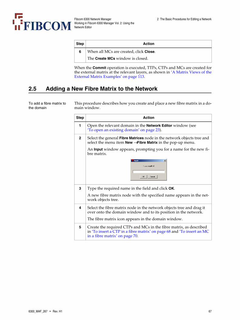
Fibcom 6300 Network ManagerWorking in Fibcom 6300 Manager Vol. 2: Using the Network Editor
2 The Basic Procedures for Editing a Network
When the Commit operation is executed, TTPs, CTPs and MCs are created forthe external matrix at the relevant layers, as shown in ‘A Matrix Views of theExternal Matrix Examples’ on page 113.
2.5 Adding a New Fibre Matrix to the Network
To add a fibre matrix to the domain
This procedure describes how you create and place a new fibre matrix in a do-main window.
6 When all MCs are created, click Close.
The Create MCs window is closed.
Step Action
Step Action
1 Open the relevant domain in the Network Editor window (see ‘To open an existing domain’ on page 23).
2 Select the general Fibre Matrices node in the network objects tree and select the menu item New → Fibre Matrix in the pop-up menu.
An Input window appears, prompting you for a name for the new fi-bre matrix.
3 Type the required name in the field and click OK.
A new fibre matrix node with the specified name appears in the net-work objects tree.
4 Select the fibre matrix node in the network objects tree and drag it over onto the domain window and to its position in the network.
The fibre matrix icon appears in the domain window.
5 Create the required CTPs and MCs in the fibre matrix, as described in ‘To insert a CTP in a fibre matrix’ on page 68 and ‘To insert an MC in a fibre matrix’ on page 70.
6300_MAF_267 • Rev. H1 67

Fibcom 6300 Network ManagerWorking in Fibcom 6300 Manager Vol. 2: Using the Network Editor
2 The Basic Procedures for Editing a Network
To insert a CTP in a fibre matrix
This procedure describes how you create a CTP in an existing fibre matrix.
Step Action
1 Open the relevant domain in the Network Editor window (see ‘To open an existing domain’ on page 23).
2 Double-click on the relevant fibre matrix icon.
The FibreMatrix window appears.
The window consists of two parts, where the upper part shows the CTPs currently connected by MCs and the lower part shows the cur-rently free CTPs.
3 Click the Insert CTP button.
An Input window appears, prompting you for a name for the new CTP.
No special format is required for CTP names in a fibre matrix. You can use the formats x, x-y, x-y-z and so on as you wish.
68 6300_MAF_267 • Rev. H1

Fibcom 6300 Network ManagerWorking in Fibcom 6300 Manager Vol. 2: Using the Network Editor
2 The Basic Procedures for Editing a Network
4 Type the required name for the CTP (for example, 1-1) and click OK.
The new CTP with the specified name appears in the Free CTPs part of the FibreMatrix window.
5 Repeat Steps 3 and 4 to create the remaining CTPs.
Each CTP is shown with a counterpart in red. This is used when drawing MCs from one CTP to another, as described in ‘To insert an MC in a fibre matrix’ on page 70.
Step Action
6300_MAF_267 • Rev. H1 69

Fibcom 6300 Network ManagerWorking in Fibcom 6300 Manager Vol. 2: Using the Network Editor
2 The Basic Procedures for Editing a Network
To insert an MC in a fibre matrix
This procedure describes how you create an MC in a fibre matrix.
Step Action
1 Open the relevant domain in the Network Editor window (see ‘To open an existing domain’ on page 23).
2 Double-click on the relevant fibre matrix icon.
The FibreMatrix window appears, showing the CTPs in the fibre ma-trix.
3 In the Free CTPs part of the window, point at the relevant CTP in the left column and press the primary mouse button.
A black rubber band line appears between the selected CTP and the mouse cursor.
4 Move the cursor to the red counterpart of the other CTP (that is, the CTP that is to be the other end point).
Note: You can also move the cursor to the actual CTP in the left-handcolumn.
70 6300_MAF_267 • Rev. H1

Fibcom 6300 Network ManagerWorking in Fibcom 6300 Manager Vol. 2: Using the Network Editor
2 The Basic Procedures for Editing a Network
When the operation is executed during a Commit operation, the network edi-tor creates the MCs in the fibre matrix at the physical layer. Then it creates alltrails that can be detected in the NEs at any layer to traverse the MCs and putsthe trails into service (see ‘The trails that are created automatically’ on page72). The client LCs served by one of these trails are also created if possible; andif the link containing such a client LC does not exist, the link is also created.
5 Release the mouse when the cursor is on the red counterpart of the CTP.
The line connects the two CTPs, indicating the MC, and the whole connection (CTPs and MC) moves up into the Connected CTPs part. The mouse cursor is then free again.
6 Repeat steps 3 to 5 to create the remaining MCs.
Step Action
6300_MAF_267 • Rev. H1 71

Fibcom 6300 Network ManagerWorking in Fibcom 6300 Manager Vol. 2: Using the Network Editor
2 The Basic Procedures for Editing a Network
The trails that are created automatically
The following rules apply to the trails that are created automatically when anMC is inserted in the network editor:
• If the end points of the new trail match the end points of a trail that exist-ed previously but has been deleted during a Commit operation, the new trail is a re-establishment of the earlier trail (except for the route). That is, the new trail gets the same identifier, end points, management state, sig-nal structure, customer, user label, revertive and perceived severity at-tribute values as the earlier trail.
• If the new trail has not existed before, it is set up with default attribute values:
• The management state In service, Free, or Free, not connected (depend-ing on the lifecycle states of the MCs in the route(s) of the trail).
• If it is a VC-4 trail, the signal structure is set to etsiVC4-threeTUG3-twentyoneTU12twentyoneTU12twentyoneTU12 (that is, ‘3x21 VC-12s’). This may, however, cause problems, as described in 9
Filtering the contents of the FibreMatrix window
Besides allowing you to hide all free CTPs and/or all connected CTPs (usingthe Hide free and Hide MCs buttons), the FibreMatrix window contains a searchfacility that enables you to show/hide CTPs with specific name formats (x,x-y, x-y-z etc.) or with specific parts of their name (for example, x-12-z). TheConnected CTPs part contains one such filter and the Free CTPs part containstwo.
Figure A) shows an example of filtering in the Connected CTPs part. The se-lected filter pattern *-*-* displays only those MCs that connect to at least oneCTP with the name format x-y-z.
72 6300_MAF_267 • Rev. H1

Fibcom 6300 Network ManagerWorking in Fibcom 6300 Manager Vol. 2: Using the Network Editor
2 The Basic Procedures for Editing a Network
Figure B) shows an example of filtering in the Free CTPs part. The selected fil-ter pattern *-*-* in the left CTP Name field affects only the left CTP column.
Note: Those CTPs that no longer are shown in the left column still have theircounterparts displayed in the right column (provided they are not fil-tered there). However, the color of these counterparts has changed toblack.
As illustrated in the figures above, filter pattern * displays all CTPs of anyname format, while the filter patterns *-* and *-*-* only display the CTPs withthe exactly corresponding name formats (that is, x-y and x-y-z, respectively).
You can mix the specification of actual part(s) of the CTP name with the useof wildcards to indicate the name format. For example, if you specify the filterpattern *-12-*, all CTPs with the name x-12-y will be displayed. However, it isnot possible to specify the filter patter *-1*-*, for example.
When you select a filter pattern in a CTP Name field, the filtering does not ac-tually take effect until you click the corresponding Search button.
2.6 Automatic Registration of 7100 NEs
Automatic Registration of 7100 NEs on 6300 NM
Automatic registration of 7100 NEs known by 7190 EMS client is done on6300NM. The 6300NM will automatically check for new 7100 NEs once every24 hours (This is done through cron job).
A special subsystem script named discover is provided for automatic discov-ery of 7100 NEs. The NEs not registered in 6300NM are registered, created,and put in a default domain named as discover_nes. The automatic registra-tion of 7100 NEs require that the discover_nes domain must be present. Themap files for the default domain are created. The script is run through thecommand nm2100 discover dcn_15.
6300_MAF_267 • Rev. H1 73

Fibcom 6300 Network ManagerWorking in Fibcom 6300 Manager Vol. 2: Using the Network Editor
2 The Basic Procedures for Editing a Network
By default, the script considers all agents known on the present central or amserver. As an optional facility on the part of user, an agent name can be givenas parameter to the command nm2100 discover dcn_15 <agentid>. When theagentid parameter is used, only NEs of the particular agent are considered forregistration, creation and domain insertion.
2.7 Adding a TeMIP Object to a Domain
To add a TeMIP object This procedure describes how to add a TeMIP object to a domain. Adding thistype of object enables alarm coloring of the specific TeMIP objects and the pos-sibility to use directives.
Step Action
1 Open the relevant domain in the Network Editor window (see ‘To open an existing domain’ on page 23).
2 Open the pop-up menu for the domain and select Insert TeMIP Ob-ject.
The Insert TeMIP Object window appears.
3 Open the Entity View window. Using the Network Management win-dow, select Operations → Entity Browser.
The Entity View window appears.
4 In the Entity View window:
a) Navigate through the entities and select the name of the specific entity.
b) Copy the full name present in the Entity field.
c) Return to the Insert TeMIP Object window.
5 Paste the full entity name in the Name field.
6 Type in a short unique name for the TeMIP object in the Nick Name field.
This nick name appears with the selected icon in the Network Man-agement window.
7 Select an icon that will represent the object in the Network Manage-ment window.
8 Click OK.
The icon and nick name you provided appear in the selected domain.
9 If you need to make more changes to the domain do them now. When all the changes are complete, select File → Commit to make the changes appear in the Network Management window.
74 6300_MAF_267 • Rev. H1
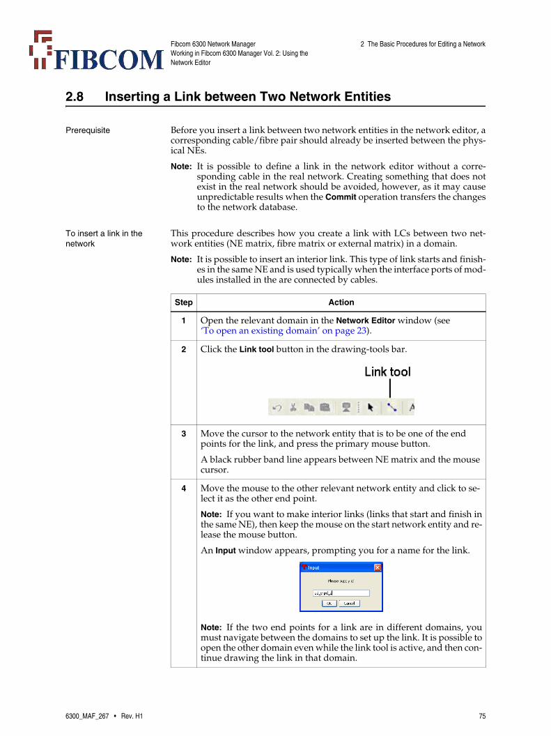
Fibcom 6300 Network ManagerWorking in Fibcom 6300 Manager Vol. 2: Using the Network Editor
2 The Basic Procedures for Editing a Network
2.8 Inserting a Link between Two Network Entities
Prerequisite Before you insert a link between two network entities in the network editor, acorresponding cable/fibre pair should already be inserted between the phys-ical NEs.
Note: It is possible to define a link in the network editor without a corre-sponding cable in the real network. Creating something that does notexist in the real network should be avoided, however, as it may causeunpredictable results when the Commit operation transfers the changesto the network database.
To insert a link in the network
This procedure describes how you create a link with LCs between two net-work entities (NE matrix, fibre matrix or external matrix) in a domain.
Note: It is possible to insert an interior link. This type of link starts and finish-es in the same NE and is used typically when the interface ports of mod-ules installed in the are connected by cables.
Step Action
1 Open the relevant domain in the Network Editor window (see ‘To open an existing domain’ on page 23).
2 Click the Link tool button in the drawing-tools bar.
3 Move the cursor to the network entity that is to be one of the end points for the link, and press the primary mouse button.
A black rubber band line appears between NE matrix and the mouse cursor.
4 Move the mouse to the other relevant network entity and click to se-lect it as the other end point.
Note: If you want to make interior links (links that start and finish inthe same NE), then keep the mouse on the start network entity and re-lease the mouse button.
An Input window appears, prompting you for a name for the link.
Note: If the two end points for a link are in different domains, youmust navigate between the domains to set up the link. It is possible toopen the other domain even while the link tool is active, and then con-tinue drawing the link in that domain.
6300_MAF_267 • Rev. H1 75

Fibcom 6300 Network ManagerWorking in Fibcom 6300 Manager Vol. 2: Using the Network Editor
2 The Basic Procedures for Editing a Network
When the operation is executed in a Commit operation, the network editor cre-ates the link in all domains where at least one of the NE matrices terminatingthe link is present.
To insert an LC between two network entities
This procedure describes how you create an LC in a link between two networkentities (NE matrix, fibre matrix or external matrix).
Note: An LC can only be created between two CTPs with the same signalId(that is, electrical to electrical or optical to optical). When you place thecursor on a CTP, a bubble text appears indicating the CTP’s signalId.
Note: Creating an LC in a link also results in the creation of all trails thattraverse the LC, when the changes are transferred from the network ed-itor to the network database.
5 Type the required name in the field and click OK.
Note: The standard naming of links is aEnd-zEnd.
The link appears as a line between the two end points. If you create an interior link, then the line appears as loop above the NE matrix entity.
Note: The link appears in all domains where the two network entitiesare shown.
Step Action
Step Action
1 Open the relevant domain in the Network Editor window (see ‘To open an existing domain’ on page 23).
2 Double-click on the line representing the link.
The Link window appears.
Note: If you have created an interior link then the aEnd and zEndhave the same CTPs.
76 6300_MAF_267 • Rev. H1

Fibcom 6300 Network ManagerWorking in Fibcom 6300 Manager Vol. 2: Using the Network Editor
2 The Basic Procedures for Editing a Network
3 If there are many LCs in the link already, you can get a better over-view of the available end points by hiding the used end points (and the LCs between them). To do this, click the Hide used button.
All CTPs already used by LCs in this link or used by LCs in other links are removed from the window.
4 Point at the relevant CTP in the aEnd and press the primary mouse button.
A black rubber band line appears between the CTP and the mouse cursor.
Note: Although in interior links the same CTPs are present on bothsides, an LC cannot be created between CTPs with the same label.
5 Keep the primary mouse button pressed and move the cursor to the relevant CTP in the zEnd.
The color of the zEnd CTP changes to green if connection is possible (that is, if the zEnd CTP has the same signalId as the aEnd CTP). Red color indicates that connection is not possible.
Note: If the two end points for a link are too far apart in the list ofCTPs, you must scroll through the list to set up the LC. It is possibleto scroll while you are drawing an LC, and then select the other endpoint.
6 If the zEnd CTP is green, click on it.
The line connects the two CTPs, indicating the LC. The mouse cursor is free again.
Step Action
6300_MAF_267 • Rev. H1 77
Fibcom 6300 Network ManagerWorking in Fibcom 6300 Manager Vol. 2: Using the Network Editor
2 The Basic Procedures for Editing a Network
When the operation is executed during a Commit operation, the network edi-tor creates the LC at the physical layer. Then it creates all trails that can be de-tected in the NEs at any layer to traverse the LC and puts the trails into service(see ‘The trails that are created automatically’ on page 78). The client LCsserved by one of these trails are also created if possible; and if the link contain-ing such a client LC does not exist, the link is also created.
The trails that are created automatically
The following rules apply to the trails that are created automatically when anLC is inserted in the network editor:
• If the end points of the new trail match the end points of a trail that exist-ed previously but has been deleted during a Commit operation, the new trail is a re-establishment of the earlier trail (except for the route). That is, the new trail gets the same identifier, end points, management state, sig-nal structure, customer, user label, revertive and perceived severity at-tribute values as the earlier trail.
• If the new trail has not existed before, it is set up with default attribute values:
• The management state In service, Free, or Free, not connected.
• If it is a VC-4 trail, the signal structure is set to etsiVC4-threeTUG3-twentyoneTU12twentyoneTU12twenty-oneTU12 (that is, ‘3x21 VC-12s’). This may, however, cause problems, as described in 9.
2.9 Changing NE Settings
The NE settings that can be changed
You can change the following parameters for an existing NE and the corre-sponding NE matrices:
• The class or type of the NE
• The name of the NE
• The name of the NE matrix (and all corresponding NE matrices)
• The nick name of the NE matrix
• The icon (in all relevant domains)
• The managing director
78 6300_MAF_267 • Rev. H1
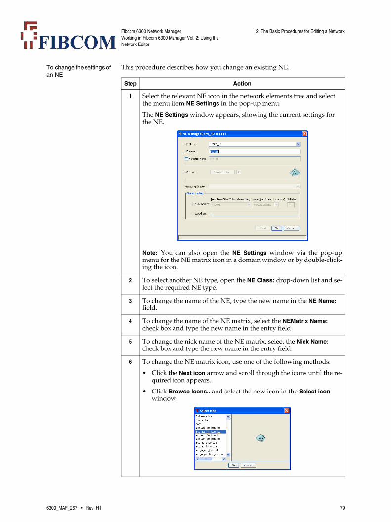
Fibcom 6300 Network ManagerWorking in Fibcom 6300 Manager Vol. 2: Using the Network Editor
2 The Basic Procedures for Editing a Network
To change the settings of an NE
This procedure describes how you change an existing NE.
Step Action
1 Select the relevant NE icon in the network elements tree and select the menu item NE Settings in the pop-up menu.
The NE Settings window appears, showing the current settings for the NE.
Note: You can also open the NE Settings window via the pop-upmenu for the NE matrix icon in a domain window or by double-click-ing the icon.
2 To select another NE type, open the NE Class: drop-down list and se-lect the required NE type.
3 To change the name of the NE, type the new name in the NE Name: field.
4 To change the name of the NE matrix, select the NEMatrix Name: check box and type the new name in the entry field.
5 To change the nick name of the NE matrix, select the Nick Name: check box and type the new name in the entry field.
6 To change the NE matrix icon, use one of the following methods:
• Click the Next icon arrow and scroll through the icons until the re-quired icon appears.
• Click Browse Icons.. and select the new icon in the Select icon window
6300_MAF_267 • Rev. H1 79

Fibcom 6300 Network ManagerWorking in Fibcom 6300 Manager Vol. 2: Using the Network Editor
2 The Basic Procedures for Editing a Network
2.10 Deleting Network Entities from the Network
To delete NE matrices, fibre matrices and external matrices
Before you can delete an NE matrix, fibre matrix or external matrix from thenetwork editor, all LCs terminating in the network entity and all links con-nected to the network entity must be deleted in the network editor (see‘To delete LCs’ on page 80 and ‘To delete links’ on page 80). When the net-work entity is ‘free’, you can delete it as described in this procedure.
To delete links To delete a link:
To delete LCs To delete an LC:
7 To specify another managing director for the NE, open the Managing Director: drop-down list and select the relevant managing director.
Step Action
Step Action
1 Select the network entity node in the relevant tree and then select the menu item Delete in the pop-up menu.
The network node disappears from the tree, and the corresponding icon disappears from all domains in the network editor where it was previously shown.
Note:
While deletion of External Matrix interface or Fibre Matrix interface, warning message will popup only if the interface is connected to LC. No message will be there if connected to trail or MC.
Step Action
1 Open the link and select the menu item Delete Link in the pop-up menu in the Link window.
The network editor removes the link from all domains in which it ap-peared.
Note: If the link contains LCs, the LCs are deleted automaticallyalong with the link.
Step Action
1 If you want to preserve the traffic in trails that normally traverse the LC at VC-x layers, reroute the trail (as described in 9) so that it no longer uses the LC.
2 Double-click on the link that contains the LC.
The Link window appears.
80 6300_MAF_267 • Rev. H1
Fibcom 6300 Network ManagerWorking in Fibcom 6300 Manager Vol. 2: Using the Network Editor
2 The Basic Procedures for Editing a Network
When trails have been rerouted and the LC has been deleted from the networkdatabase, you can remove the cable/fibre pair in the real network.
To delete an interface from an external matrix
To delete an interface from an external matrix:
To delete an MC from an external matrix
To delete an MC from an external matrix:
3 In the Link window, select the line that represents the LC and then click the Delete LC button.
The network editor deletes the LC in the Link window.
When the Commit operation is executed, the network editor removes the LC itself and also all trails that traverse the LC at any layer from the network database. All LCs that are served by the deleted trails are also removed. If a link at any layer is emptied by the operation, the link is also removed.
Note: The trails are not removed from the NEs in the real network.
Step Action
Step Action
1 Double-click on the external matrix icon in the domain window.
The ExternalMatrix window appears.
2 Open the pop-up menu for the interface in the tree structure and se-lect the menu item Delete.
The network editor deletes the interface in the tree structure.
Note: You can delete several interfaces at once by selecting the rele-vant parent node.
When the Commit operation is executed, the network editor removes the interface itself, all related MCs and also all trails that traverse the interface at any layer from the network database.
Note: The trails are not removed from the NEs in the real network.
All LCs that are served by one of the trails are removed. If a link at any layer is emptied by the operation, the link is also removed.
Step Action
1 Double-click on the external matrix icon in the domain window.
The ExternalMatrix window appears.
2 Click the Create MCs button.
The Create MCs window is displayed.
3 In the Create MCs window, select the relevant toggle button to dis-play the MC.
6300_MAF_267 • Rev. H1 81

Fibcom 6300 Network ManagerWorking in Fibcom 6300 Manager Vol. 2: Using the Network Editor
2 The Basic Procedures for Editing a Network
To delete an MC from a fibre matrix
To delete an MC from a fibre matrix:
To delete CTPs from a fibre matrix
Before you can delete a CTP from a fibre matrix, you must make sure that theCTP is ‘free’ to be deleted. This means that any LC and MC terminated in theCTP must first be deleted (see ‘To delete LCs’ on page 80 and ‘To delete an MCfrom a fibre matrix’ on page 82). To delete a free CTP:
4 Click on the line representing the MC to select it and then click the Delete MC button.
The MC line disappears.
When the Commit operation is executed, the network editor removes the MC itself and also all trails that traverse the MC at any layer from the network database.
Note: The trails are not removed from the NEs in the real network.
All LCs that are served by one of the trails are removed. If a link at any layer is emptied by the operation, the link is also removed.
Step Action
Step Action
1 Double-click on the fibre matrix icon in the domain window.
The FibreMatrix window appears.
2 Select the MC in the Connected CTPs part of the FibreMatrix window and click the Delete MC button.
The network editor deletes the MC in the FibreMatrix window.
When the Commit operation is executed, the network editor removes the MC itself and also all trails that traverse the MC at any layer from the network database.
Note: The trails are not removed from the NEs in the real network.
All LCs that are served by one of the trails are removed. If a link at any layer is emptied by the operation, the link is also removed.
Step Action
1 Double-click on the fibre matrix icon in the domain window.
The FibreMatrix window appears.
2 Select the CTP in the Free CTPs part of the FibreMatrix window and click the Delete CTP button.
The network editor deletes the CTP in the FibreMatrix window.
When the Commit operation is executed, the network editor removes the CTP itself from the network database.
82 6300_MAF_267 • Rev. H1

Fibcom 6300 Network ManagerWorking in Fibcom 6300 Manager Vol. 2: Using the Network Editor
2 The Basic Procedures for Editing a Network
2.11 Uploading Information from the Network
Automatic or manual upload
When you open the Network Editor window, the configuration of the NEs isuploaded from the Element Access to the editor memory.
You can, however, also upload configuration information for the individualNEs “manually” to the network database when committing (for example,when new cards have been added to an NE). The network editor contains anupload operation for that purpose. See ‘To upload the NE configuration fromNetwork Manager’ on page 85 for a description of how to use that operation.
Note: The upload is not carried out in the network database until the Commitoperation is executed.
To upload the NE configuration from Network Editor
In most cases, when you create a new NE in the list of NEs, an equipment up-load is carried out automatically. However, you can also upload the configu-ration of the corresponding NE(s) to one or more NE matrices later on in oneoperation. This procedure describes how to specify which NE matrices to up-load information to and how to activate the upload operation.
Step Action
1 Open the relevant domain in the Network Editor window (see ‘To open an existing domain’ on page 23).
2 Drag a “lasso” around the relevant NE matrix icons with the mouse to select them.
When you release the mouse, the “lasso” disappears and the NE ma-trix icons are shown with handles, to indicate that they are selected.
6300_MAF_267 • Rev. H1 83
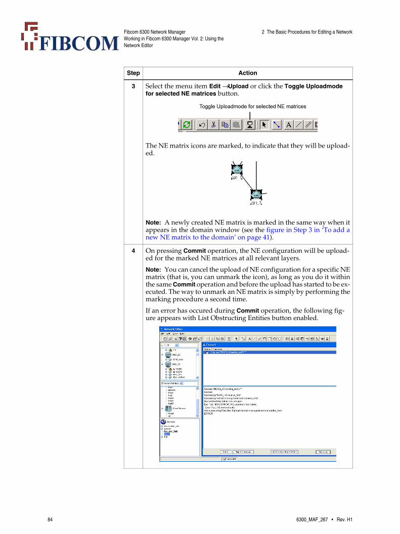
Fibcom 6300 Network ManagerWorking in Fibcom 6300 Manager Vol. 2: Using the Network Editor
2 The Basic Procedures for Editing a Network
3 Select the menu item Edit → Upload or click the Toggle Uploadmode for selected NE matrices button.
The NE matrix icons are marked, to indicate that they will be upload-ed.
Note: A newly created NE matrix is marked in the same way when itappears in the domain window (see the figure in Step 3 in ‘To add anew NE matrix to the domain’ on page 41).
4 On pressing Commit operation, the NE configuration will be upload-ed for the marked NE matrices at all relevant layers.
Note: You can cancel the upload of NE configuration for a specific NEmatrix (that is, you can unmark the icon), as long as you do it withinthe same Commit operation and before the upload has started to be ex-ecuted. The way to unmark an NE matrix is simply by performing themarking procedure a second time.
If an error has occured during Commit operation, the following fig-ure appears with List Obstructing Entities button enabled.
Step Action
84 6300_MAF_267 • Rev. H1

Fibcom 6300 Network ManagerWorking in Fibcom 6300 Manager Vol. 2: Using the Network Editor
2 The Basic Procedures for Editing a Network
To upload the NE configuration from Network Manager
This procedure describes how to specify which NE matrices to upload infor-mation to and how to activate the upload operation form the Network Manag-er.
5 On pressing List Obstructing Entities, a new Dialog i.e. Obstructing Entities is launched listing the obstructing entities which could be any of these entities i.e. trails, LCs or packet links in a table with their respective IDs and AEnd and ZEnd points. You can select the indi-vidual entity or select multiple entities and perform delete operation by pressing the Delete Entities button.
Step Action
Step Action
1 Open the Network Manager window. Select the NE for which upload operation is to be carried out.
2 Right click on selected NE, select the menu item Tools → Upload to Network Database.
6300_MAF_267 • Rev. H1 85

Fibcom 6300 Network ManagerWorking in Fibcom 6300 Manager Vol. 2: Using the Network Editor
2 The Basic Procedures for Editing a Network
3 On pressing Upload to Network Database on NE, Upload Message Di-alog is launched.
It has two radio buttons i.e. Resolve Conflicts & Show Conflicts and a check box Local Reestablish Trails.
The user may unselect Local Reestablish Trails checkbox as required. The user may also select one out of Show Conflicts and Resolve Con-flicts.
Unselect the Local Reestablish Trails check box postpones the rees-tablish trails after a number of uploads, which is more efficient.
4 On pressing OK in the Message Dialog the Upload directive is fired and the Progress monitor Dialog is launched which displays the result of the directive as it progresses.
In the Upload Dialog there are two buttons Close and List Obstruct-ing Entities. List Obstructing Entities would be enabled only when the user selected Show Conflicts in the previous step and there are some inconsistencies between NM data base and actual NE configu-rations discovered during Upload process.
Step Action
86 6300_MAF_267 • Rev. H1
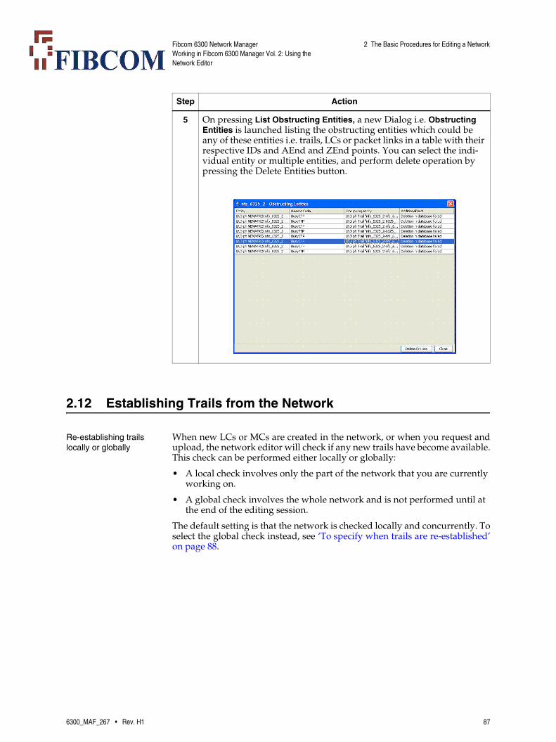
Fibcom 6300 Network ManagerWorking in Fibcom 6300 Manager Vol. 2: Using the Network Editor
2 The Basic Procedures for Editing a Network
2.12 Establishing Trails from the Network
Re-establishing trails locally or globally
When new LCs or MCs are created in the network, or when you request andupload, the network editor will check if any new trails have become available.This check can be performed either locally or globally:
• A local check involves only the part of the network that you are currently working on.
• A global check involves the whole network and is not performed until at the end of the editing session.
The default setting is that the network is checked locally and concurrently. Toselect the global check instead, see ‘To specify when trails are re-established’on page 88.
5 On pressing List Obstructing Entities, a new Dialog i.e. Obstructing Entities is launched listing the obstructing entities which could be any of these entities i.e. trails, LCs or packet links in a table with their respective IDs and AEnd and ZEnd points. You can select the indi-vidual entity or multiple entities, and perform delete operation by pressing the Delete Entities button.
Step Action
6300_MAF_267 • Rev. H1 87

Fibcom 6300 Network ManagerWorking in Fibcom 6300 Manager Vol. 2: Using the Network Editor
2 The Basic Procedures for Editing a Network
To specify when trails are re-established
You can specify whether trails are to be re-established locally (the default set-ting) or globally. This procedure describes how to change the current setting.
2.13 Creating and Re-organizing Domains
Working with domains We recommend that you organize your network model in a hierarchy of do-mains and subdomains, according to traffic type, geography or topology.Each domain within that hierarchy represents a group of network resources.The procedures below describe how you work with the domains themselveswithin the network editor. That is:
• How you create a new domain
• How you create a domain hierarchy by using existing domains as subdo-mains
• How you rearrange the contents of domains in a domain hierarchy, by moving some of the contents of one domain into another domain (using cut and paste)
• How you transfer any changes in the domain hierarchy to the Network Management window
• How you specify whether you want to use NE matrix icons or NE icons.
• How you create graphics objects in a domain
• How you add a background to a domain.
Note: You can show the same matrix or link in several domains. For example,a link can be shown with aEnd in one domain and zEnd in another.
Step Action
1 Select the menu entry File → Properties or click the Properties button.
The Properties window appears, containing a Reestablish Trails mode: part with a Local and a Global toggle button.
2 Click the required toggle button and then click OK.
The Properties window is closed and the new setting takes effect.
88 6300_MAF_267 • Rev. H1
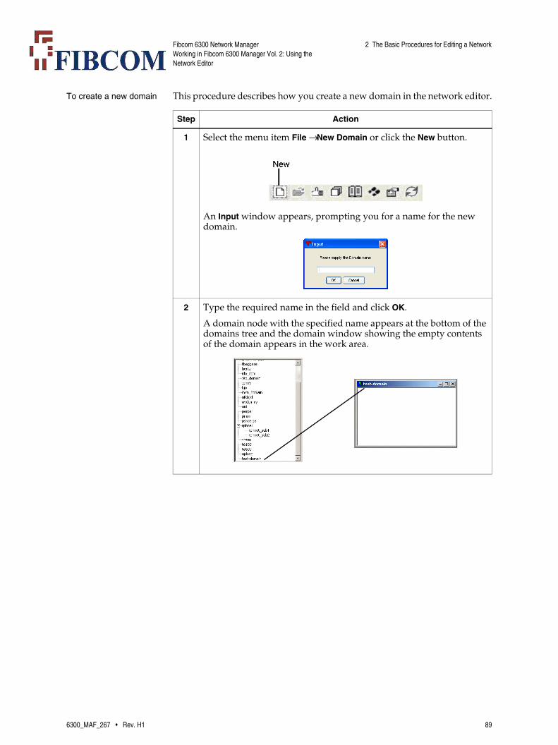
Fibcom 6300 Network ManagerWorking in Fibcom 6300 Manager Vol. 2: Using the Network Editor
2 The Basic Procedures for Editing a Network
To create a new domain This procedure describes how you create a new domain in the network editor.
Step Action
1 Select the menu item File → New Domain or click the New button.
An Input window appears, prompting you for a name for the new domain.
2 Type the required name in the field and click OK.
A domain node with the specified name appears at the bottom of the domains tree and the domain window showing the empty contents of the domain appears in the work area.
6300_MAF_267 • Rev. H1 89
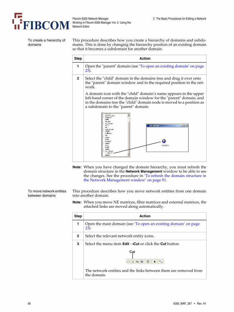
Fibcom 6300 Network ManagerWorking in Fibcom 6300 Manager Vol. 2: Using the Network Editor
2 The Basic Procedures for Editing a Network
To create a hierarchy of domains
This procedure describes how you create a hierarchy of domains and subdo-mains. This is done by changing the hierarchy position of an existing domainso that it becomes a subdomain for another domain.
Note: When you have changed the domain hierarchy, you must refresh thedomain structure in the Network Management window to be able to seethe changes. See the procedure in ‘To refresh the domain structure inthe Network Management window’ on page 91.
To move network entities between domains
This procedure describes how you move network entities from one domaininto another domain.
Note: When you move NE matrices, fibre matrices and external matrices, theattached links are moved along automatically.
Step Action
1 Open the "parent" domain (see ‘To open an existing domain’ on page 23).
2 Select the "child" domain in the domains tree and drag it over onto the "parent" domain window and to the required position in the net-work.
A domain icon with the "child" domain’s name appears in the upper left-hand corner of the domain window for the "parent" domain, and in the domains tree the "child" domain node is moved to a position as a subdomain to the "parent" domain.
Step Action
1 Open the main domain (see ‘To open an existing domain’ on page 23).
2 Select the relevant network entity icons.
3 Select the menu item Edit → Cut or click the Cut button.
The network entities and the links between them are removed from the domain.
90 6300_MAF_267 • Rev. H1

Fibcom 6300 Network ManagerWorking in Fibcom 6300 Manager Vol. 2: Using the Network Editor
2 The Basic Procedures for Editing a Network
To refresh the domain structure in the Network Management window
When you change the domain hierarchy in the network editor, the changes arenot transferred to the open Network Management window. To refresh the do-main structure:
To specify the use of NE matrix icons or NE icons
You can specify whether the icons shown in the domains are NE matrix iconsor NE icons. This procedure describes how to change the current setting.
4 Open the subdomain window and then paste the network entities into the domain window, either by selecting the menu item Edit → Paste or by clicking on the Paste button.
The network entities and the links between them appear in the do-main window for the subdomain.
Step Action
Step Action
1 In the Network Management window, select the menu item Navigation → Reset Domain Hierarchy.
The domain structure seen from the Network Management window is refreshed so that is includes the recent changes made in the network editor.
Step Action
1 Select the menu entry File → Properties or click the Properties button.
The Properties window appears, containing an Icon mode: part with an NE Icons and a Matrix Icons toggle button.
2 Click the required toggle button and then click OK.
The Properties window is closed and the new setting takes effect.
6300_MAF_267 • Rev. H1 91
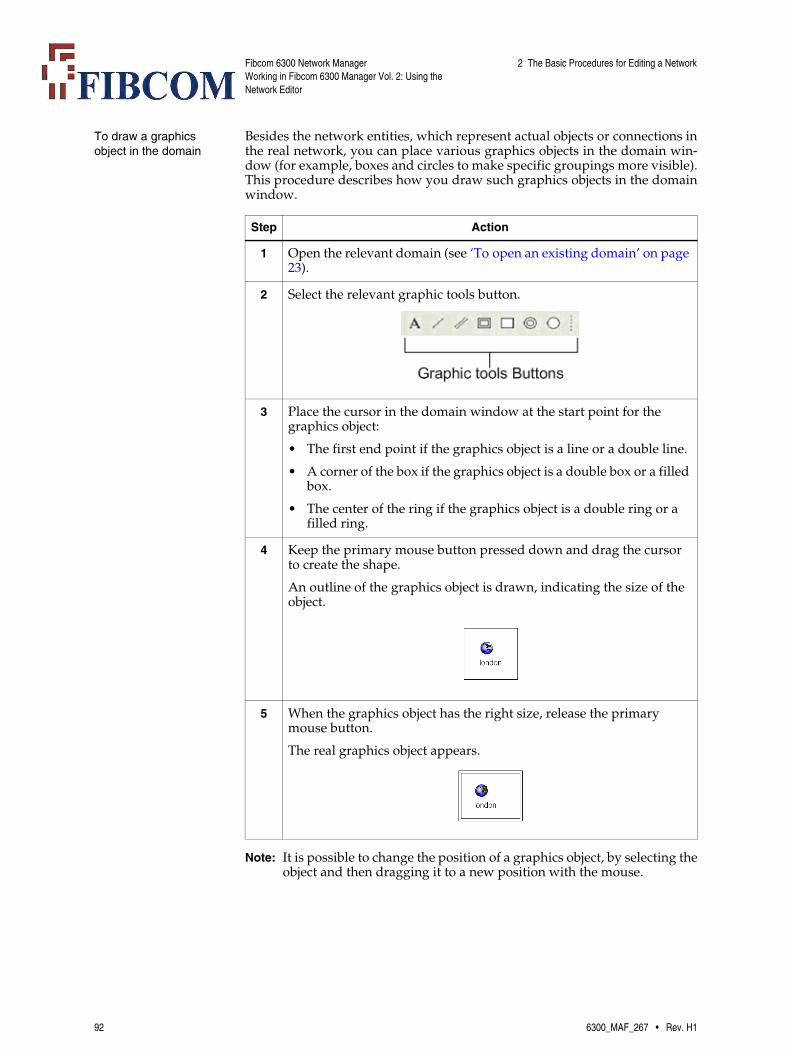
Fibcom 6300 Network ManagerWorking in Fibcom 6300 Manager Vol. 2: Using the Network Editor
2 The Basic Procedures for Editing a Network
To draw a graphics object in the domain
Besides the network entities, which represent actual objects or connections inthe real network, you can place various graphics objects in the domain win-dow (for example, boxes and circles to make specific groupings more visible).This procedure describes how you draw such graphics objects in the domainwindow.
Note: It is possible to change the position of a graphics object, by selecting theobject and then dragging it to a new position with the mouse.
Step Action
1 Open the relevant domain (see ‘To open an existing domain’ on page 23).
2 Select the relevant graphic tools button.
3 Place the cursor in the domain window at the start point for the graphics object:
• The first end point if the graphics object is a line or a double line.
• A corner of the box if the graphics object is a double box or a filled box.
• The center of the ring if the graphics object is a double ring or a filled ring.
4 Keep the primary mouse button pressed down and drag the cursor to create the shape.
An outline of the graphics object is drawn, indicating the size of the object.
5 When the graphics object has the right size, release the primary mouse button.
The real graphics object appears.
92 6300_MAF_267 • Rev. H1

Fibcom 6300 Network ManagerWorking in Fibcom 6300 Manager Vol. 2: Using the Network Editor
2 The Basic Procedures for Editing a Network
To write text in the domain
In the domain window, you can place text that is not connected to any specificobject. This procedure describes how you create that kind of text.
Note: It is possible to change the position of a text, by clicking on the text toselect it and then dragging it to a new position with the mouse.
To add a background to the domain
This procedure describes how you use a graphics file as background in the do-main window (that is, how you add a backdrop to a domain). The default set-ting for a new domain is no background.
Note: Initially, for a new system, when the user selects this option, a messagepops up with information that there are no backdrop images available.This is because, there are no images available for selection and only thesyatem administrator can insert images at relevent location(s) in theserver.
Step Action
1 Open the relevant domain (see ‘To open an existing domain’ on page 23).
2 Click the Text tool button in the drawing tool bar.
3 Place the mouse cursor where you want the text to appear in the do-main window and press the primary mouse button.
An Input window appears, prompting you for the new text.
4 Type the relevant text in the field and click OK.
The text is now placed in the domain at the position where you clicked with the text tool.
Step Action
1 Open the relevant domain (see ‘To open an existing domain’ on page 23).
6300_MAF_267 • Rev. H1 93

Fibcom 6300 Network ManagerWorking in Fibcom 6300 Manager Vol. 2: Using the Network Editor
2 The Basic Procedures for Editing a Network
Note: To remove the background in a domain, select the menu item File → Re-move backdrop.
2 Select the menu item File → Set backdrop as ....
The Select backdrop window is opened, listing the available back-drop files.
3 Select the relevant graphics file as background and then click OK.
The contents of the selected file appears as background in the do-main window.
Step Action
94 6300_MAF_267 • Rev. H1

Fibcom 6300 Network ManagerWorking in Fibcom 6300 Manager Vol. 2: Using the Network Editor
3 Examples of Work Scenarios
3 Examples of Work Scenarios
Overview The use of the network editor is described in a few typical work situations(scenarios):
• ‘3.2 Inserting a New NE Matrix in the Network’ on page 96
• ‘3.3 Inserting a New NE Matrix by Modifying the Existing Network’ on page 98
• ‘3.4 Moving Two Links’ on page 100
• ‘3.5 Synchronizing NE Matrices with NEs’ on page 102
• ‘3.6 Inserting a Fibre Matrix in the Network’ on page 104
• ‘3.7 Inserting an External Matrix in the Network’ on page 107
• ‘3.8 Inserting an External Matrix Representing a Leased Line’ on page 109
• ‘3.9 Inserting a TeMIP Object in the DCN Domain’ on page 111
Each work procedure combines a number of the individual basic proceduresdescribed in ‘2 The Basic Procedures for Editing a Network’ on page 37.
3.1 Introduction
Symbols used in examples
The procedures are described in connection with specific network examples.The following symbols are used in the examples:
6300_MAF_267 • Rev. H1 95
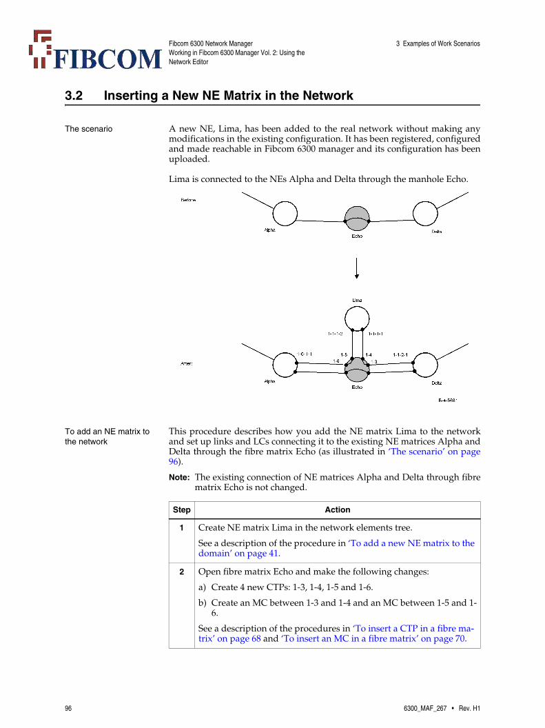
Fibcom 6300 Network ManagerWorking in Fibcom 6300 Manager Vol. 2: Using the Network Editor
3 Examples of Work Scenarios
3.2 Inserting a New NE Matrix in the Network
The scenario A new NE, Lima, has been added to the real network without making anymodifications in the existing configuration. It has been registered, configuredand made reachable in Fibcom 6300 manager and its configuration has beenuploaded.
Lima is connected to the NEs Alpha and Delta through the manhole Echo.
To add an NE matrix to the network
This procedure describes how you add the NE matrix Lima to the networkand set up links and LCs connecting it to the existing NE matrices Alpha andDelta through the fibre matrix Echo (as illustrated in ‘The scenario’ on page96).
Note: The existing connection of NE matrices Alpha and Delta through fibrematrix Echo is not changed.
Step Action
1 Create NE matrix Lima in the network elements tree.
See a description of the procedure in ‘To add a new NE matrix to the domain’ on page 41.
2 Open fibre matrix Echo and make the following changes:
a) Create 4 new CTPs: 1-3, 1-4, 1-5 and 1-6.
b) Create an MC between 1-3 and 1-4 and an MC between 1-5 and 1-6.
See a description of the procedures in ‘To insert a CTP in a fibre ma-trix’ on page 68 and ‘To insert an MC in a fibre matrix’ on page 70.
96 6300_MAF_267 • Rev. H1
Fibcom 6300 Network ManagerWorking in Fibcom 6300 Manager Vol. 2: Using the Network Editor
3 Examples of Work Scenarios
3 Place NE matrix Lima in the domain window.
See a description of the procedure in ‘To add a new NE matrix to the domain’ on page 41
4 Select the link tool and draw a link between NE matrix Lima and fi-bre matrix Echo.
See a description of the procedure in ‘To insert a link in the network’ on page 75.
5 Open link Lima-Echo and create the following 2 LCs:
• One LC between CTP 1-1-1-1 in NE matrix Lima and CTP 1-4 in fibre matrix Echo
• One LC between CTP 1-1-1-2 in NE matrix Lima and CTP 1-5 in fibre matrix Echo.
See a description of the procedure in ‘To insert an LC between two network entities’ on page 76.
6 Open link Alpha-Echo and create an LC with the following end points:
• CTP 1-6-1-1 in NE matrix Alpha
• CTP 1-6 in fibre matrix Echo.
See a description of the procedure in ‘To insert an LC between two network entities’ on page 76.
7 Open link Echo-Delta and create an LC with the end points:
• CTP 1-3 in fibre matrix Echo
• CTP 1-1-2-1 in NE matrix Delta.
See a description of the procedure in ‘To insert an LC between two network entities’ on page 76.
8 Commit the changes to the network database.
See a description of the procedure in ‘To transfer (commit) your work in the network editor to the network database’ on page 29.
Step Action
6300_MAF_267 • Rev. H1 97

Fibcom 6300 Network ManagerWorking in Fibcom 6300 Manager Vol. 2: Using the Network Editor
3 Examples of Work Scenarios
3.3 Inserting a New NE Matrix by Modifying the Existing Network
The scenario A new NE, Tetra, has been added to the real network and has been added tothe list of NEs in Fibcom 6300 manager’s network editor (its configuration hasbeen uploaded at the same time).
NE Tetra is included in the route of the physical trail between NEs Alpha andBeta, changing the previous route from NE Alpha through manholes Echoand Rio to NE Beta to two new physical routes where NE Tetra is placed be-tween the two manholes.
The proper cross connections have been set up in the new NE so that trafficwas only interrupted while the cables where moved.
Note: The LCs between NEs Alpha and Beta and the two manholes are un-changed in the new route. The LC between the two manholes is also un-changed. The only changes are made in the manholes, where MCs aremoved.
98 6300_MAF_267 • Rev. H1
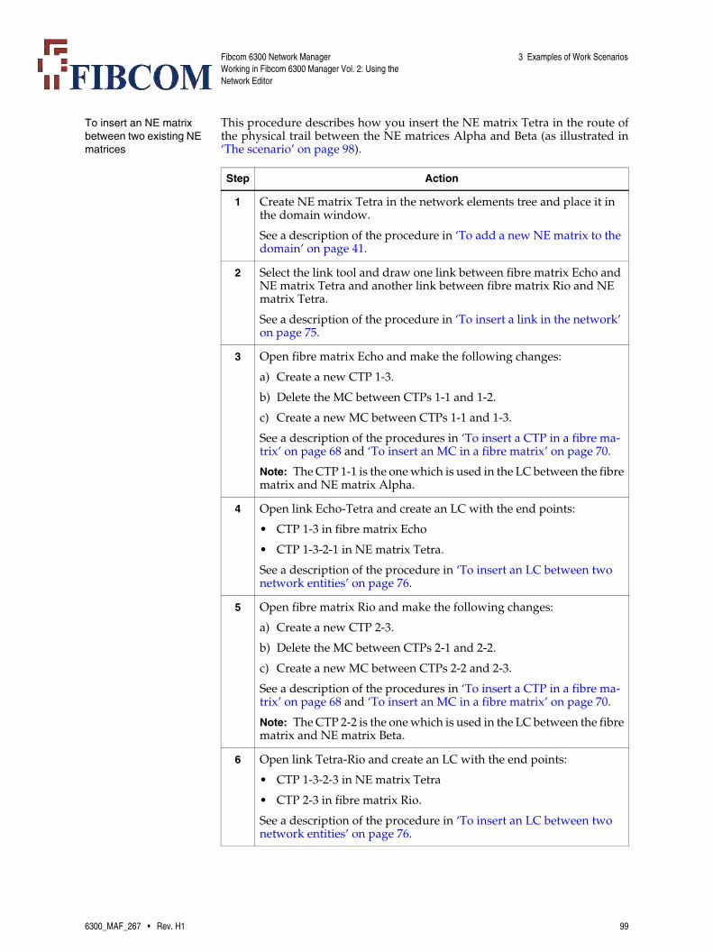
Fibcom 6300 Network ManagerWorking in Fibcom 6300 Manager Vol. 2: Using the Network Editor
3 Examples of Work Scenarios
To insert an NE matrix between two existing NE matrices
This procedure describes how you insert the NE matrix Tetra in the route ofthe physical trail between the NE matrices Alpha and Beta (as illustrated in‘The scenario’ on page 98).
Step Action
1 Create NE matrix Tetra in the network elements tree and place it in the domain window.
See a description of the procedure in ‘To add a new NE matrix to the domain’ on page 41.
2 Select the link tool and draw one link between fibre matrix Echo and NE matrix Tetra and another link between fibre matrix Rio and NE matrix Tetra.
See a description of the procedure in ‘To insert a link in the network’ on page 75.
3 Open fibre matrix Echo and make the following changes:
a) Create a new CTP 1-3.
b) Delete the MC between CTPs 1-1 and 1-2.
c) Create a new MC between CTPs 1-1 and 1-3.
See a description of the procedures in ‘To insert a CTP in a fibre ma-trix’ on page 68 and ‘To insert an MC in a fibre matrix’ on page 70.
Note: The CTP 1-1 is the one which is used in the LC between the fibrematrix and NE matrix Alpha.
4 Open link Echo-Tetra and create an LC with the end points:
• CTP 1-3 in fibre matrix Echo
• CTP 1-3-2-1 in NE matrix Tetra.
See a description of the procedure in ‘To insert an LC between two network entities’ on page 76.
5 Open fibre matrix Rio and make the following changes:
a) Create a new CTP 2-3.
b) Delete the MC between CTPs 2-1 and 2-2.
c) Create a new MC between CTPs 2-2 and 2-3.
See a description of the procedures in ‘To insert a CTP in a fibre ma-trix’ on page 68 and ‘To insert an MC in a fibre matrix’ on page 70.
Note: The CTP 2-2 is the one which is used in the LC between the fibrematrix and NE matrix Beta.
6 Open link Tetra-Rio and create an LC with the end points:
• CTP 1-3-2-3 in NE matrix Tetra
• CTP 2-3 in fibre matrix Rio.
See a description of the procedure in ‘To insert an LC between two network entities’ on page 76.
6300_MAF_267 • Rev. H1 99

Fibcom 6300 Network ManagerWorking in Fibcom 6300 Manager Vol. 2: Using the Network Editor
3 Examples of Work Scenarios
3.4 Moving Two Links
The scenario A new NE section, consisting of two NEs (Sirius and Beta) and a connectionbetween them, has been inserted in the real network. The two cables that pre-viously connected NEs Delta and Gamma to the NE Tetra have been movedso that Delta is now connected to Sirius and Gamma is connected to Beta (thatis, Sirius and Beta replace Tetra).
The proper cross-connections have been set up in the new NE section, so traf-fic was interrupted only while the two cables were moved.
A representation of the new section, consisting of Sirius and Beta and the con-nection between them, has already been set up in the network editor.
7 Commit the changes to the network database.
See a description of the procedure in ‘To transfer (commit) your work in the network editor to the network database’ on page 29.
Step Action
100 6300_MAF_267 • Rev. H1

Fibcom 6300 Network ManagerWorking in Fibcom 6300 Manager Vol. 2: Using the Network Editor
3 Examples of Work Scenarios
To move two links from one NE section to another
This procedure describes how you change the two links Delta-Tetra and Tetra-Gamma to the links Delta-Sirius and Gamma-Beta (as illustrated in ‘The sce-nario’ on page 100).
Step Action
1 Delete the links Delta-Tetra and Tetra-Gamma.
See a description of the procedure in ‘To delete links’ on page 80.
2 Select the link tool and draw a link between the NE matrices Delta and Sirius.
See a description of the procedure in ‘To insert a link in the network’ on page 75.
3 Open link Delta-Sirius and create an LC with the end points:
• CTP 1-5-1-1 in NE matrix Delta
• CTP 2-1-1-1 in NE matrix Sirius.
See a description of the procedure in ‘To insert an LC between two network entities’ on page 76.
Note: The CTP in NE matrix Delta is the one that was previously usedby the link removed in Step 1.
4 Select the link tool and draw a link between the NE matrices Beta and Gamma.
See a description of the procedure in ‘To insert a link in the network’ on page 75.
5 Open link Gamma-Beta and create an LC with the end points:
• CTP 1-2-4-1 in NE matrix Gamma
• CTP 1-1-2-6 in NE matrix Beta.
See a description of the procedure in ‘To insert an LC between two network entities’ on page 76.
Note: The CTP in NE matrix Gamma is the one that was previouslyused by the link removed in Step 1.
6 Commit the changes to the network database.
See a description of the procedure in ‘To transfer (commit) your work in the network editor to the network database’ on page 29.
6300_MAF_267 • Rev. H1 101
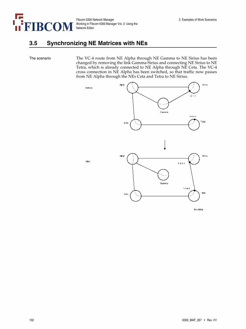
Fibcom 6300 Network ManagerWorking in Fibcom 6300 Manager Vol. 2: Using the Network Editor
3 Examples of Work Scenarios
3.5 Synchronizing NE Matrices with NEs
The scenario The VC-4 route from NE Alpha through NE Gamma to NE Sirius has beenchanged by removing the link Gamma-Sirius and connecting NE Sirius to NETetra, which is already connected to NE Alpha through NE Ceta. The VC-4cross connection in NE Alpha has been switched, so that traffic now passesfrom NE Alpha through the NEs Ceta and Tetra to NE Sirius.
102 6300_MAF_267 • Rev. H1

Fibcom 6300 Network ManagerWorking in Fibcom 6300 Manager Vol. 2: Using the Network Editor
3 Examples of Work Scenarios
To synchronize an NE matrix after changing the trail route
This procedure describes how you change the link Sirius-Gamma to the linkSirius-Tetra and also synchronize NE matrix Alpha (as illustrated in ‘The sce-nario’ on page 102).
Step Action
1 Delete the link Sirius-Gamma.
See a description of the procedure in ‘To delete links’ on page 80.
2 Select the link tool and draw a link between the NE matrices Sirius and Tetra.
See a description of the procedure in ‘To insert a link in the network’ on page 75.
3 Open link Sirius-Tetra and create an LC with the end points:
• CTP 1-2-1-1 in NE matrix Sirius
• CTP 1-1-4-1 in NE matrix Tetra.
See a description of the procedure in ‘To insert an LC between two network entities’ on page 76.
Note: The CTP in NE matrix Sirius is the one that was previouslyused by the link removed in Step 1.
Note: The CTP in NE matrix Tetra is the one connected to the rest ofthe VC-4 trail.
4 Mark NE matrix Alpha to have its NE configuration uploaded.
See a description of the procedure in ‘To upload the NE configura-tion from Network Manager’ on page 85.
Note: In some NEs (for example, Marconi XC-1), it is not possible toswitch one end point of a VC-4 cross connection.If this is the case for NE matrix Alpha, a new VC-4 cross connection isuploaded instead and the old one is discarded. This will mean that theVC-4 trail is not re-established during the execution of the Commit op-eration, but a new VC-4 trail is created instead.
5 Commit the changes to the network database.
See a description of the procedure in ‘To transfer (commit) your work in the network editor to the network database’ on page 29.
6300_MAF_267 • Rev. H1 103

Fibcom 6300 Network ManagerWorking in Fibcom 6300 Manager Vol. 2: Using the Network Editor
3 Examples of Work Scenarios
3.6 Inserting a Fibre Matrix in the Network
The scenario In the real network, the connection between NEs Alpha and Ceta and the con-nection between NEs Gamma and Ceta actually pass through the manholeEcho. This has not yet been registered in Fibcom 6300 manager.
104 6300_MAF_267 • Rev. H1

Fibcom 6300 Network ManagerWorking in Fibcom 6300 Manager Vol. 2: Using the Network Editor
3 Examples of Work Scenarios
To insert a fibre matrix in the network
This procedure describes how you insert fibre matrix Echo in the network andthen change the links Alpha-Ceta and Gamma-Ceta to pass through the newfibre matrix (as illustrated in ‘The scenario’ on page 104).
Step Action
1 Create fibre matrix Echo in the network objects tree and place it in the domain window.
See a description of the procedure in ‘To add a fibre matrix to the do-main’ on page 67.
2 Open the fibre matrix Echo and make the following configuration:
a) Insert CTPs 1-1, 1-2, 1-3 and 1-4.
b) Create an MC between CTPs 1-1 and 1-3 and an MC between CTPs 1-2 and 1-4.
c) Click OK to close the fibre matrix.
See a description of the procedures in ‘To insert a CTP in a fibre ma-trix’ on page 68 and ‘To insert an MC in a fibre matrix’ on page 70.
3 Delete the links Alpha-Ceta and Gamma-Ceta.
See a description of the procedure in ‘To delete links’ on page 80.
4 Select the link tool and draw one link between NE matrix Alpha and fibre matrix Echo, and another link between fibre matrix Echo and NE matrix Ceta.
See a description of the procedure in ‘To insert a link in the network’ on page 75.
5 Open link Alpha-Echo and create an LC with the end points:
• CTP 1-1-1-2 in NE matrix Alpha
• CTP 1-1 in fibre matrix Echo.
See a description of the procedure in ‘To insert an LC between two network entities’ on page 76.
Note: The CTP in NE matrix Alpha is the one that was previouslyused by the link removed in Step 3.
6 Open link Echo-Ceta and create an LC with the end points:
• CTP 1-3 in fibre matrix Echo
• CTP 2-1-1-2 in NE matrix Ceta.
See a description of the procedure in ‘To insert an LC between two network entities’ on page 76.
Note: The CTP in NE matrix Ceta is the one that was previously usedby the link removed in Step 3.
6300_MAF_267 • Rev. H1 105
Fibcom 6300 Network ManagerWorking in Fibcom 6300 Manager Vol. 2: Using the Network Editor
3 Examples of Work Scenarios
7 Repeat Steps 4 to 6 to create one link and LC between NE matrix Gamma and fibre matrix Echo, and one link and LC between fibre matrix Echo and NE matrix Ceta.
Use the following end points for the LC between Gamma and Echo:
• CTP 1-3-2-2 in NE matrix Gamma (used by the LC in the link de-leted in Step 3).
• CTP 1-2 in fibre matrix Echo.
Use the following end points for the LC between Echo and Ceta:
• CTP 1-4 in fibre matrix Echo
• CTP 2-1-1-4 in NE matrix Ceta (used by the LC in the link deleted in Step 3).
8 Commit the changes to the network database.
See a description of the procedure in ‘To transfer (commit) your work in the network editor to the network database’ on page 29.
Step Action
106 6300_MAF_267 • Rev. H1

Fibcom 6300 Network ManagerWorking in Fibcom 6300 Manager Vol. 2: Using the Network Editor
3 Examples of Work Scenarios
3.7 Inserting an External Matrix in the Network
The scenario NEs Ceta and Tetra are connected to a network that is not managed by Fibcom6300 manager. To be able to manage the trails that go via this ‘foreign’ net-work, the interfaces to the network are represented by external matrixNetwork2 in Fibcom 6300 manager.
6300_MAF_267 • Rev. H1 107

Fibcom 6300 Network ManagerWorking in Fibcom 6300 Manager Vol. 2: Using the Network Editor
3 Examples of Work Scenarios
To insert an external matrix in the network
This procedure describes how you insert external matrix Network2 in the net-work and let it represent the ‘foreign’ network connected to NEs Ceta and Tet-ra (as illustrated in ‘The scenario’ on page 107).
Step Action
1 Create external matrix Network2 in the network objects tree and place it in the domain window.
See a description of the procedure in ‘To add an external matrix to the domain’ on page 46.
2 Open the external matrix Network2 and represent the two interfaces in the ‘foreign’ network with the relevant interface types for ports 1-1-1-1 and 1-1-1-2.
See a description of the procedures in ‘Deciding which interface types are needed’ on page 45 and ‘To create SDH and PDH interfac-es’ on page 48.
3 Select the link tool and draw a link between NE matrix Ceta and ex-ternal matrix Network2.
See a description of the procedure in ‘To insert a link in the network’ on page 75.
4 Open link Ceta-Network2 and create an LC with the end points:
• CTP 1-3-1-1 in NeMatrix Ceta
• CTP 1-1-1-1 in external matrix Network2.
See a description of the procedure in ‘To insert an LC between two network entities’ on page 76.
5 Repeat Steps 3 to 4 to create another link and LC between NE matrix Tetra and external matrix Network2.
Use the following end points for the LC:
• CTP 1-1-4-2 in NE matrix Tetra
• CTP 1-1-1-2 in external matrix Network2.
6 Commit the changes to the network database.
See a description of the procedure in ‘To transfer (commit) your work in the network editor to the network database’ on page 29.
108 6300_MAF_267 • Rev. H1

Fibcom 6300 Network ManagerWorking in Fibcom 6300 Manager Vol. 2: Using the Network Editor
3 Examples of Work Scenarios
3.8 Inserting an External Matrix Representing a Leased Line
The scenario A specific VC-12 line has been leased in the network belonging to the supplierSaturn. Our network uses this line as part of the route for a trail and is con-nected to it via the NEs Delta and Alpha. To be able to manage the trail goingvia the leased line, the line is represented by the inflexible external matrix Sat-urn.
6300_MAF_267 • Rev. H1 109

Fibcom 6300 Network ManagerWorking in Fibcom 6300 Manager Vol. 2: Using the Network Editor
3 Examples of Work Scenarios
To insert an external matrix that represents a leased line
This procedure describes how you insert external matrix Saturn in the net-work and let it represent the leased VC-12 line in the Saturn network (as illus-trated in ‘The scenario’ on page 109).
Step Action
1 Create external matrix Saturn in the network objects tree and place it in the domain window.
See a description of the procedure in ‘To add an external matrix to the domain’ on page 46.
2 Open the external matrix Saturn and represent the two interfaces at either end of the leased line with the relevant interface structures for ports 2-4-1-5 and 3-1-1-2.
Note: The naming of the ports corresponds to the actual placement ofthe ports in the NEs in the Saturn network.
See a description of the procedures in ‘Deciding which interface types are needed’ on page 45 and ‘To create SDH and PDH interfac-es’ on page 48.
3 Select the link tool and draw a link between NE matrix Delta and ex-ternal matrix Saturn.
See a description of the procedure in ‘To insert a link in the network’ on page 75.
4 Open link Delta-Saturn and create an LC with the end points:
• CTP 1-2-1-3 in Ne Matrix Delta
• CTP 2-4-1-5 in external matrix Saturn.
See a description of the procedure in ‘To insert an LC between two network entities’ on page 76.
5 Repeat Steps 3 to 4 to create another link and LC between NE matrix Alpha and external matrix Saturn.
Use the following end points for the LC:
• CTP 1-4-1-1 in NE matrix Alpha
• CTP 3-1-1-2 in external matrix Saturn.
6 Commit the changes to the network database.
See a description of the procedure in ‘To transfer (commit) your work in the network editor to the network database’ on page 29.
7 Open the VC-4 domain in the Network Management window ad set up one VC-4 trail between NE matrix Delta and external matrix Sat-urn and another VC-4 trail between NE matrix Alpha and external matrix Saturn.
See a description of the procedure in [5].
8 Open the Matrix View for external matrix Saturn at the VC-12 layer, make the external matrix inflexible at that layer and create the matrix connection representing the leased line.
See a description of the Matrix View and the relevant procedures in [5].
110 6300_MAF_267 • Rev. H1

Fibcom 6300 Network ManagerWorking in Fibcom 6300 Manager Vol. 2: Using the Network Editor
3 Examples of Work Scenarios
3.9 Inserting a TeMIP Object in the DCN Domain
To insert a TeMIP object in the DCN domain
This procedure describes how to add a DCN_10 child entity to the DCN do-main. When DCN_10 child entities for NEs are added to this domain it is pos-sible to create a graphical representation of your actual DCN network. By add-ing child entities for each of the NEs present in the network, it is possible toobtain alarms in the Network Management window when communication toone or more of these NEs is lost.
9 Display the VC-12 network layer in the Network Management win-dow and set up the VC-12 trail transversing the leased line.
See a description of the trail set-up procedure in [5].
Step Action
Step Action
1 Open the DCN domain in the Network Editor window (see ‘To open an existing domain’ on page 23).
2 Open the pop-up menu for the domain and select Insert TeMIP Ob-ject.
The Insert TeMIP Object window appears.
3 Open the Entity View window. Using the Network Management win-dow, select Operations → Entity Browser.
The Entity View window appears.
4 In the Entity View window:
a) Select DCN_10 in the Global Classes list. All the child entities un-der this object appear in a list.
b) Select the NE class that you want to monitor, for example t6325_10_ccf. A new NE child entity appears below the selected NE class.
c) Select NE. A list of all the NEs created in this class appears.
d) Select Show in the pop-up menu for the specific NE object present in your network. A Directive View window appears.
e) Copy the text that appears in the Entity field of the Directive View window. This is the full name for the entity.
f) Click the bell icon (Top) to return to the Global Classes list.
g) Return to the Insert TeMIP Object window.
5 Paste the full entity name in the Name field.
6 Type in a short unique name for the NE in the Nick Name field.
This nick name appears with the selected icon in the Network Man-agement window.
6300_MAF_267 • Rev. H1 111

Fibcom 6300 Network ManagerWorking in Fibcom 6300 Manager Vol. 2: Using the Network Editor
3 Examples of Work Scenarios
7 Select the temip_dt_term_icon.dat icon. This will represent the NE in the Network Management window.
The mcc_dcn_10_ne_icon.dat option produces a small icon which has the nick name label located on the right-hand side of the icon.
8 Click OK.
The icon and nick name you provided appear in the DCN domain.
9 Repeat Steps 2 through 8 until all the child entities for the NEs present in the network are included in the dcn domain.
You are now able to see colored DCN alarms for the separate NEs in the Network Management window.
Step Action
112 6300_MAF_267 • Rev. H1
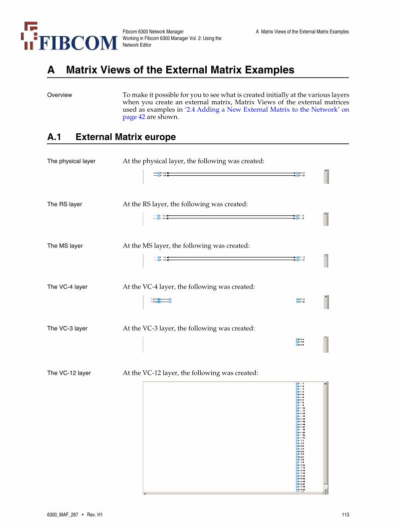
Fibcom 6300 Network ManagerWorking in Fibcom 6300 Manager Vol. 2: Using the Network Editor
A Matrix Views of the External Matrix Examples
A Matrix Views of the External Matrix Examples
Overview To make it possible for you to see what is created initially at the various layerswhen you create an external matrix, Matrix Views of the external matricesused as examples in ‘2.4 Adding a New External Matrix to the Network’ onpage 42 are shown.
A.1 External Matrix europe
The physical layer At the physical layer, the following was created:
The RS layer At the RS layer, the following was created:
The MS layer At the MS layer, the following was created:
The VC-4 layer At the VC-4 layer, the following was created:
The VC-3 layer At the VC-3 layer, the following was created:
The VC-12 layer At the VC-12 layer, the following was created:
6300_MAF_267 • Rev. H1 113

Fibcom 6300 Network ManagerWorking in Fibcom 6300 Manager Vol. 2: Using the Network Editor
A Matrix Views of the External Matrix Examples
A.2 External Matrix wdm_nets
The physical layer At the physical layer, the following was created:
The OMS layer At the OMS layer, the following was created:
The OCH layer At the OCH layer, the following was created:
The RS layer At the RS layer, the following was created:
A.3 External Matrix VCG_ETH
The physical layer At the physical layer, the following was created:
The VC-4 layer At the VC-4 layer, the following was created:
The VC-3 layer At the VC-3 layer, the following was created:
The VC-12 layer At the VC-12 layer, the following was created:
114 6300_MAF_267 • Rev. H1
Fibcom 6300 Network ManagerWorking in Fibcom 6300 Manager Vol. 2: Using the Network Editor
Index
Index
AAlignment buttons 24Arrows
use of 8
BBackground
adding 93Bold
use of 8Buttons 16
for aligning and distributing 19for graphic tools 18for operations 17
CCommit button
using 29Commit menu item 29Commit operation
activating 29if problem occurs 33
Commit window 30using 29
Courieruse of 8
Create MCs windowusing 63, 65, 81
Create NEMatrix menu item 41CTPs
deleting from FibreMatrix 82inserting in FibreMatrix 68
Cut buttonusing 90
Cut menu item 90
DDelete menu item 80Distribution buttons 24Domains
creating hierarchy 90creating new 89moving network entities between 90opening 23refreshing domain structure 91re-organizing 88using as subdomains 90
Drawing tools
using 92
EETEX NEs
adding 40Ethernet address
where to find it 39Exit menu item 28Exit window 34
Delete and Exit button warning 34using 28
External Matrix menu item 47ExternalMatrices
adding 46creating ETH and VCG intrfaces 56creating interface structure 48creating required MCs 62creating SDH and PDH interfaces 48creating WDM interfaces 53deciding configuration 44deleting 80deleting interface 81deleting MC 81flexibility 42inflexibility 42inserting (work scenario) 107interface types 44moving to subdomain 90representing leased line (work scenario) 109
ExternalMatrix window 48using 48, 53, 56, 81
FFibre Matrix menu item 67FibreMatrices
adding 67deleting 80inserting (work scenario) 104moving to subdomain 90
FibreMatrix windowusing 68, 69, 70, 82
GGenerate Map Files window
using 27Generate maps button
using 27Generate Maps menu item 27Generating map files 27
6300_MAF_267 • Rev. H1 115

Fibcom 6300 Network ManagerWorking in Fibcom 6300 Manager Vol. 2: Using the Network Editor
Index
Graphics objectsdrawing 92
IIcons in domain window
arranging 24using NE matrix or NE icons 91
Input windowusing 47, 67, 68, 75, 89, 93
Insert Interface windowusing 49, 54, 57
Insert menu item 49, 54, 57Interfaces
deleting from ExternalMatrix 81Interior links 75Italics
use of 8
KKeyboard shortcuts
using 8
LLayers
working wth 13LCs
deleting 80inserting 76
Link tool buttonusing 75
Link windowusing 76, 80, 81
Linksdeleting 80inserting 75moving (work scenario) 100moving to subdomain 90
Logviewew window 32
MMap files
generating 27MCs
creating required in ExternalMatrix 62deleting from ExternalMatrix 81deleting from FibreMatrix 82inserting in FibreMatrix 70
Menu structureindication of 8
Menus 15Monospaced font
use of 8
Mouse buttonprimary 8secondary 8
NNE matrices
adding 41cancelling upload 84changing NE settings 79deleting 80moving to subdomain 90uploading NE configuration from network
editor 83uploading NE configuration from network
manager 85NEMatrices
inserting (work scenario) 96inserting in link (work scenario) 98synchronizing (work scenario) 102uploading (work scenario) 102
NEsadding 37adding ETEX NEs 40changing settings 79
Network editingwork environment 12
Network Editorprinciples of 14
Network Editor window 12closing 28handling objects in 23opening 14working in 21
Network layersworking with 13
Network Management windowrefreshing domain structure 91
New buttonusing 89
New Domain menu itemin File menu 89
New menu itemExternal Matrix 47FibreMatrix 67
NSAP addressdescription of 39
OOpen button
using 23Open domain menu item 23
116 6300_MAF_267 • Rev. H1

Fibcom 6300 Network ManagerWorking in Fibcom 6300 Manager Vol. 2: Using the Network Editor
Index
PPaste button
using 91Paste menu item 91Primary mouse button 8Procedures
basic 37work scenarios 95
Properties menu item 88, 91Properties window 88, 91
QQuotation marks
use of 8
RRemove backdrop menu item 94Reset Domain Hierarchy menu item 91
SSecondary mouse button 8Set backdrop as .. menu item 94Show trail log button
using 35Show Trail Log menu item 35Show Trail Log window
using 35Signal structure
settings for VC-4 trail 62Sort menu item 22Sorting nodes in a tree 22Style conventions 8Subdomains
creating 90moving network entities to 90
sub-multiplex checkboxin Setup Trail window 50, 57
TText
writing 93Text tool button
using 93Toggle Uploadmode for selected NE matrices
buttonusing 84, 85, 86, 87
Toolbar buttons 16for aligning and distributing 19for graphic tools 18for operations 17
Trail log 34
displaying 35Tree structure
sorting nodes 22
UUpload
List Obstructing Entities 85, 87Local Reestablish Trails 86Show Conflicts 86
Upload menu item 84, 85, 86, 87Uploading 83, 85
WWarning
using the Delete and Exit button 34
6300_MAF_267 • Rev. H1 117

Fibcom 6300 Network ManagerWorking in Fibcom 6300 Manager Vol. 2: Using the Network Editor
Index
118 6300_MAF_267 • Rev. H1