fiberglass reinforced plastics (frp) as the construction ... · pdf fileup to 300 ⁰c author:...
TRANSCRIPT
Fiberglass Reinforced Plastics (FRP) as the Construction Material of Chimney Liners and Ducts in Power Plants with Bypass Conditions and Temperatures up to 300⁰C
Author: Jelle WARNAR, Robert KOENIS
Company: Plasticon Composites International Contracting BV
Country: The Netherlands
Presented during the Power-Gen India & Central Asia during the Conference
Program, on Friday 19 May 2017, New-Delhi, India
2
This document is owned and written by Plasticon Composites International Contracting BV | [email protected] | Phone: +31(0)88 – 85 85 000 | www.plasticoncomposites.com
Index
1. Introduction .......................................................................................................................................... 3
1.1 Ambient Air Quality ....................................................................................................................... 3
1.2 Flue Gas Desulphurization ............................................................................................................ 3
1.3 Reconsideration of material used for construction ........................................................................ 3
1.4 Bypass conditions ......................................................................................................................... 4
1.5 Temperature resistance of FRP .................................................................................................... 5
1.6 In reality ......................................................................................................................................... 5
2. General assumptions and information ................................................................................................. 6
2.1 No track record .............................................................................................................................. 6
2.2 In short: construction of a FRP laminate ....................................................................................... 6
2.2.1 Glass material ............................................................................................................................ 7
2.2.2 Resin .......................................................................................................................................... 7
2.2.3 HDT of a resin ............................................................................................................................ 8
2.3 Calculation methods ...................................................................................................................... 8
2.3.1 Example of the assessment of an FRP construction ................................................................. 9
3. Research for temperatures up to 300° Celsius ................................................................................. 10
3.1 Impact of temperature ................................................................................................................. 10
3.1.1 Laminate temperature .............................................................................................................. 10
3.2 Load design ................................................................................................................................. 10
4. The theory behind a high temperature .............................................................................................. 12
4.1 Design base ................................................................................................................................ 12
4.2 Laminate and stiffeners ............................................................................................................... 13
4.3 Check of design / axial stress (dead weight, process & thermal expansion) .............................. 15
4.4 Check of design / buckling factor (from external pressure) ........................................................ 16
5. Degradation of mechanical properties .............................................................................................. 17
5.1 Tensile tests by Indian Institute of Technology, Madras ............................................................. 17
5.3 Bending tests by University of Aachen ....................................................................................... 18
5.4 Outcome of the tests ................................................................................................................... 18
6. Conclusion ......................................................................................................................................... 20
3
This document is owned and written by Plasticon Composites International Contracting BV | [email protected] | Phone: +31(0)88 – 85 85 000 | www.plasticoncomposites.com
1. Introduction
1.1 Ambient Air Quality
As of January 1st, this year, the Indian Government revised the environmental norms for thermal power plants to cut pollution. The new standard is aimed at reducing emission of particulate matter (PM), Sulphur Dioxide, and Oxide of Nitrogen, which will in turn help bring about an improvement in the Ambient Air Quality (AAQ) in and around thermal power stations in India. This means, India wants to enhance the quality of the air which has positive effects for people’s health.
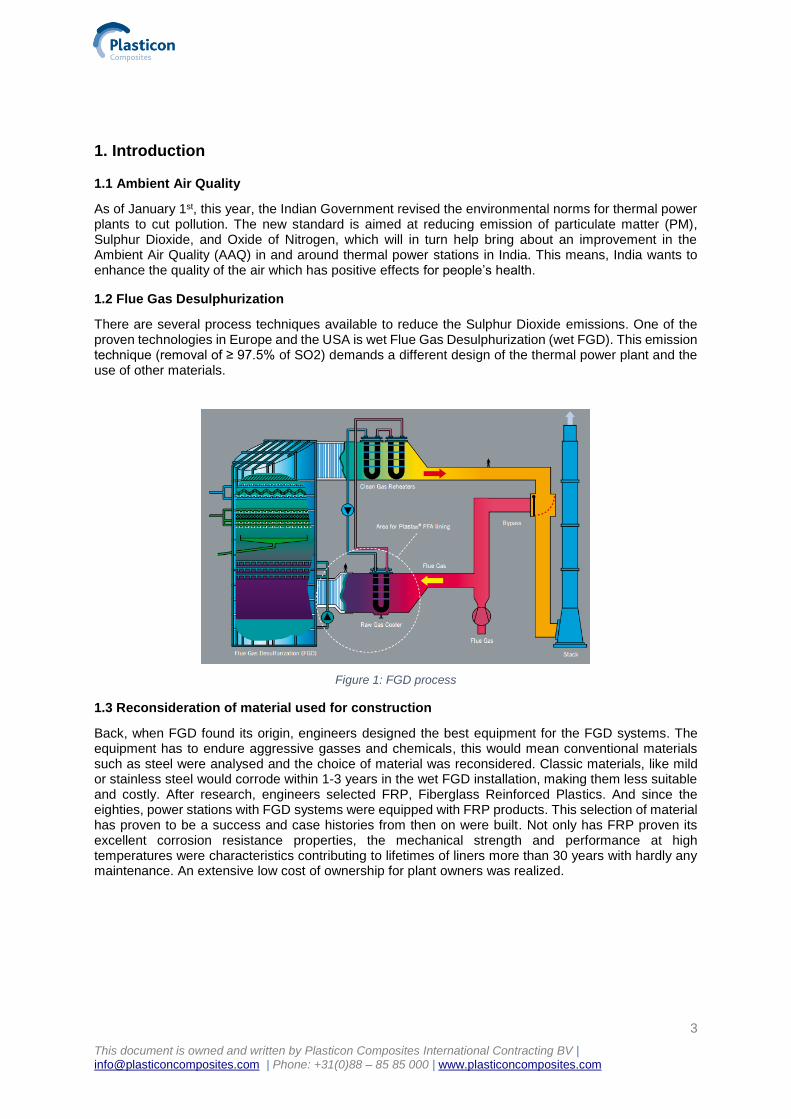
1.2 Flue Gas Desulphurization
There are several process techniques available to reduce the Sulphur Dioxide emissions. One of the proven technologies in Europe and the USA is wet Flue Gas Desulphurization (wet FGD). This emission technique (removal of ≥ 97.5% of SO2) demands a different design of the thermal power plant and the use of other materials.
Figure 1: FGD process
1.3 Reconsideration of material used for construction
Back, when FGD found its origin, engineers designed the best equipment for the FGD systems. The equipment has to endure aggressive gasses and chemicals, this would mean conventional materials such as steel were analysed and the choice of material was reconsidered. Classic materials, like mild or stainless steel would corrode within 1-3 years in the wet FGD installation, making them less suitable and costly. After research, engineers selected FRP, Fiberglass Reinforced Plastics. And since the eighties, power stations with FGD systems were equipped with FRP products. This selection of material has proven to be a success and case histories from then on were built. Not only has FRP proven its excellent corrosion resistance properties, the mechanical strength and performance at high temperatures were characteristics contributing to lifetimes of liners more than 30 years with hardly any maintenance. An extensive low cost of ownership for plant owners was realized.
4
This document is owned and written by Plasticon Composites International Contracting BV | [email protected] | Phone: +31(0)88 – 85 85 000 | www.plasticoncomposites.com
Chemical Max. concentration
H₂O 25.6 [vol%]
SO₂ 2,500 [mg/m3]
SO₃ 20 [mg/m3]
HCl 20 - 200 [mg/m3]
HF 5 – 30 [mg/m3]
CO 500 [mg/m3]
NOₓ 400 [mg/m3]
Figure 2: The composition of the flue gas
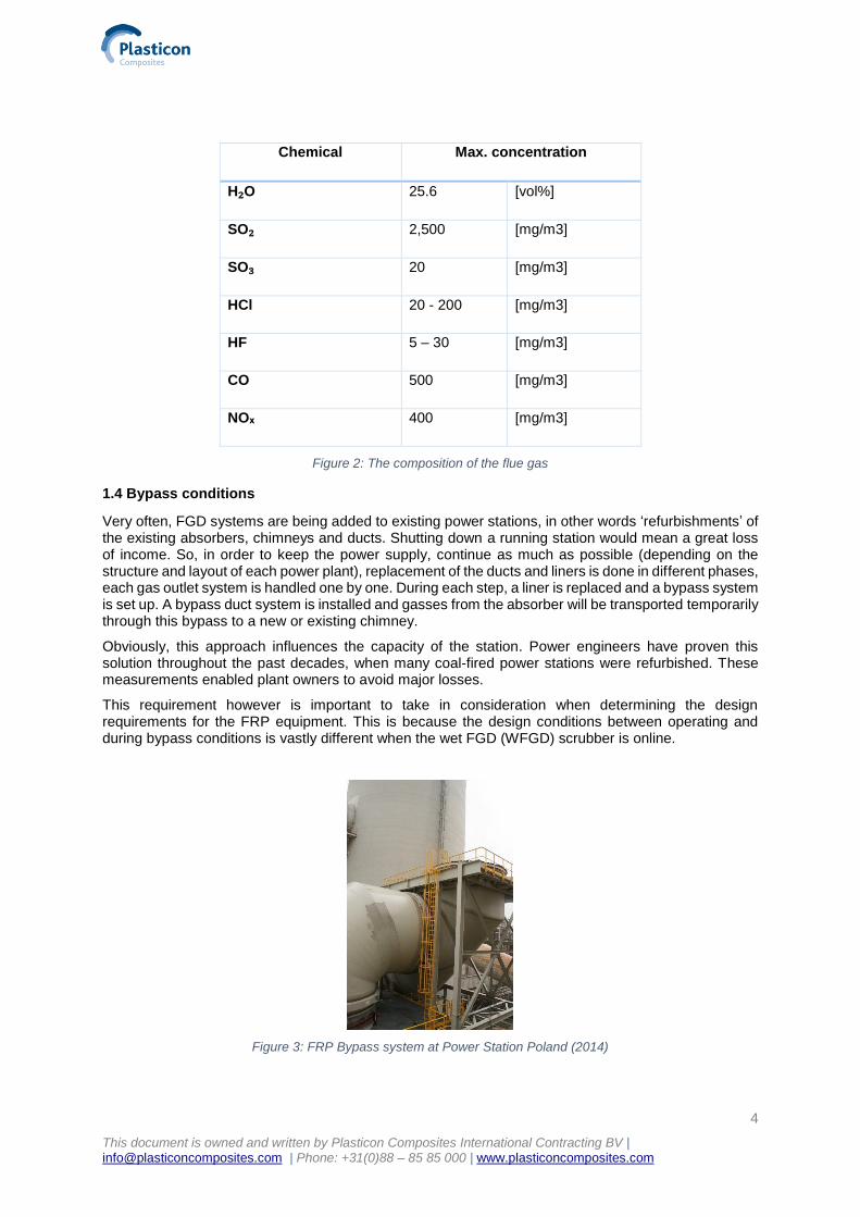
1.4 Bypass conditions
Very often, FGD systems are being added to existing power stations, in other words ‘refurbishments’ of the existing absorbers, chimneys and ducts. Shutting down a running station would mean a great loss of income. So, in order to keep the power supply, continue as much as possible (depending on the structure and layout of each power plant), replacement of the ducts and liners is done in different phases, each gas outlet system is handled one by one. During each step, a liner is replaced and a bypass system is set up. A bypass duct system is installed and gasses from the absorber will be transported temporarily through this bypass to a new or existing chimney.
Obviously, this approach influences the capacity of the station. Power engineers have proven this solution throughout the past decades, when many coal-fired power stations were refurbished. These measurements enabled plant owners to avoid major losses.
This requirement however is important to take in consideration when determining the design requirements for the FRP equipment. This is because the design conditions between operating and during bypass conditions is vastly different when the wet FGD (WFGD) scrubber is online.
Figure 3: FRP Bypass system at Power Station Poland (2014)
5
This document is owned and written by Plasticon Composites International Contracting BV | [email protected] | Phone: +31(0)88 – 85 85 000 | www.plasticoncomposites.com
1.5 Temperature resistance of FRP
For a normal set up FGD process, FRP has proven itself to be excellent choice of material for ducts and liners. Under normal circumstances, a wet FGD installation operates at a temperature of about 70°C. Therefore engineers cope with the question: how would FRP perform during bypass conditions? Process engineers examined the circumstances during a bypass operation. Chemical resistance, mechanical strength and practical topics turned out to be nonetheless a reason to stick with FRP. However, engineers defined the operating temperature under severe bypass conditions to be unregular and high peeks could occur.
The bypass system however has to be designed for an excursion temperature up to 300 °Celsius (30 min).
1.6 In reality
Practically, it turns out that during start up after a shutdown, the power plant firstly uses with heavy oil under bypass condition. During by-pass operation, the temperature of the system can reach temperatures up to max 165°C and with maximum SO2 concentrations. During operation, there is a small possibility that once in the lifetime of a power plant, the temperature of the flue gas will go up to a temperature of 300°C for no longer than a period of 30 minutes.
Different engineering companies in India have stated that this is a condition that should be taken in count. The reason might be that all possible risks must of course be avoided. Besides, the refurbishment constructions of existing coal-fired power stations with FGD systems is something relatively unknown for the Indian market.
However, with this new requirement added, more focus was created to explore the temperature
resistance at a temperature of 300 °C FRP for a duration of no longer than 30-minutes time. These
requirements come from the engineers from leading EPC’s responsible for the design and projects of
refurbishments of some key coal-fired power stations in India.
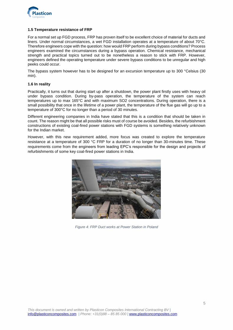
Figure 4: FRP Duct works at Power Station in Poland
6
This document is owned and written by Plasticon Composites International Contracting BV | [email protected] | Phone: +31(0)88 – 85 85 000 | www.plasticoncomposites.com
2. General assumptions and information
In order to understand the question about the temperatures and the effect on FRP materials, one needs
to have a deeper understanding of the raw materials used, how FRP is designed and manufactured.
2.1 No track record
Never before did the market demand an excursion temperature resistance of 300 °C of FRP material.
For instance, high temperature equipment used for waste incineration plants was a combination of FRP
and Fluor Plastic lining materials, known for its high temperature and chemical resistant characteristics.
In these cases severe conditions were expected and investment are done based on these operations.
Normal conditions at coal-fired Power Stations are less severe and the equipment does not necessarily
operate under temperatures higher than 70 °C. What needs to be stated:
Till today, no problems ever occurred related to high temperatures and FRP ducts and liners.
Leading European engineers and designers from companies with extensive experience in designing
power stations, FGD processes and other gas cleaning systems, such as MHPS, BNG or Alstom Power.
2.2 In short: construction of a FRP laminate
Making a suitable FRP duct, chimney, absorber or any product for industrial usage requires design and
engineering by people with extensive FRP experience and knowledge. FRP, Fibreglass Reinforced
Plastic, is a composition of resin and glass fibres. Both resin and glass are to be selected based on the
application. The FRP product consists of a 1) inner laminate, called a CBL, Chemical Barrier Layer; 2)
the structural layer; 3) top layer. The type and percentage of glass fibres varies from 30% wt. up to 70%
wt. depending on the functionality of the layer.
1. The Chemical Barrier Layer protects the structural layer against influences from the inside
(flue gas), it consists of 70% resin and 30% glass;
2. The Structural Layer carries the load, it consists of 30% resin and 70% glass;
3. The Top Layer protects the Structural Layer against influences from the outside.
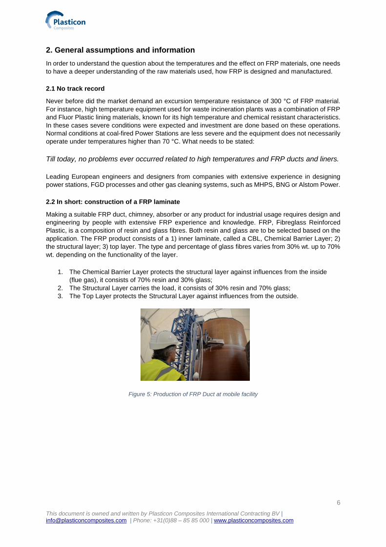
Figure 5: Production of FRP Duct at mobile facility
7
This document is owned and written by Plasticon Composites International Contracting BV | [email protected] | Phone: +31(0)88 – 85 85 000 | www.plasticoncomposites.com
2.2.1 Glass material
Different types of technical glass roving’s and fabrics are available, but for FGD applications E-CR glass
is used. This is specified by industrial standards and selected due to its excellent performance in
corrosive environments, such as FGD systems. Requirements for the E-CR glass fibre are written in the
EN 13121-1 or ASTM D5364. Depending on the design requirements, different types of glass
reinforcements can be used to build up a laminate.
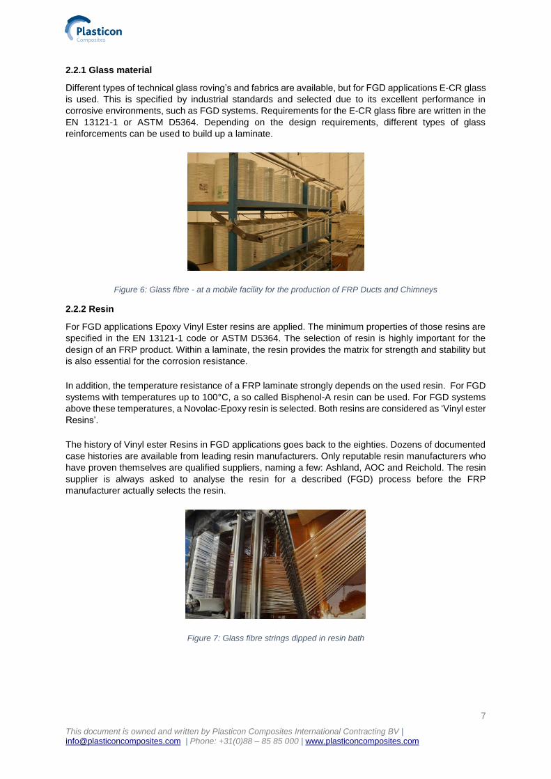
Figure 6: Glass fibre - at a mobile facility for the production of FRP Ducts and Chimneys
2.2.2 Resin
For FGD applications Epoxy Vinyl Ester resins are applied. The minimum properties of those resins are
specified in the EN 13121-1 code or ASTM D5364. The selection of resin is highly important for the
design of an FRP product. Within a laminate, the resin provides the matrix for strength and stability but
is also essential for the corrosion resistance.
In addition, the temperature resistance of a FRP laminate strongly depends on the used resin. For FGD
systems with temperatures up to 100°C, a so called Bisphenol-A resin can be used. For FGD systems
above these temperatures, a Novolac-Epoxy resin is selected. Both resins are considered as ‘Vinyl ester
Resins’.
The history of Vinyl ester Resins in FGD applications goes back to the eighties. Dozens of documented
case histories are available from leading resin manufacturers. Only reputable resin manufacturers who
have proven themselves are qualified suppliers, naming a few: Ashland, AOC and Reichold. The resin
supplier is always asked to analyse the resin for a described (FGD) process before the FRP
manufacturer actually selects the resin.
Figure 7: Glass fibre strings dipped in resin bath
8
This document is owned and written by Plasticon Composites International Contracting BV | [email protected] | Phone: +31(0)88 – 85 85 000 | www.plasticoncomposites.com
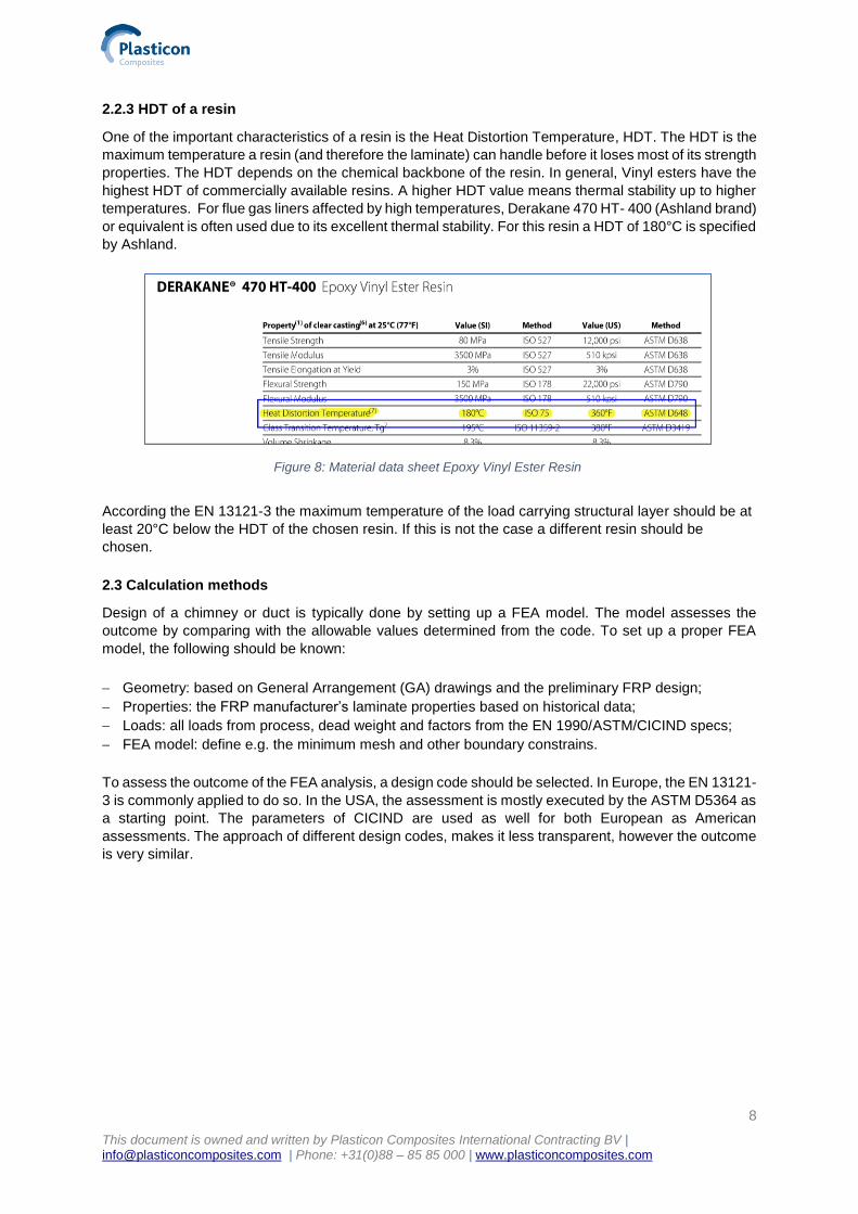
2.2.3 HDT of a resin
One of the important characteristics of a resin is the Heat Distortion Temperature, HDT. The HDT is the
maximum temperature a resin (and therefore the laminate) can handle before it loses most of its strength
properties. The HDT depends on the chemical backbone of the resin. In general, Vinyl esters have the
highest HDT of commercially available resins. A higher HDT value means thermal stability up to higher
temperatures. For flue gas liners affected by high temperatures, Derakane 470 HT- 400 (Ashland brand)
or equivalent is often used due to its excellent thermal stability. For this resin a HDT of 180°C is specified
by Ashland.
According the EN 13121-3 the maximum temperature of the load carrying structural layer should be at
least 20°C below the HDT of the chosen resin. If this is not the case a different resin should be
chosen.
2.3 Calculation methods
Design of a chimney or duct is typically done by setting up a FEA model. The model assesses the
outcome by comparing with the allowable values determined from the code. To set up a proper FEA
model, the following should be known:
Geometry: based on General Arrangement (GA) drawings and the preliminary FRP design;
Properties: the FRP manufacturer’s laminate properties based on historical data;
Loads: all loads from process, dead weight and factors from the EN 1990/ASTM/CICIND specs;
FEA model: define e.g. the minimum mesh and other boundary constrains.
To assess the outcome of the FEA analysis, a design code should be selected. In Europe, the EN 13121-
3 is commonly applied to do so. In the USA, the assessment is mostly executed by the ASTM D5364 as
a starting point. The parameters of CICIND are used as well for both European as American
assessments. The approach of different design codes, makes it less transparent, however the outcome
is very similar.
Figure 8: Material data sheet Epoxy Vinyl Ester Resin
9
This document is owned and written by Plasticon Composites International Contracting BV | [email protected] | Phone: +31(0)88 – 85 85 000 | www.plasticoncomposites.com
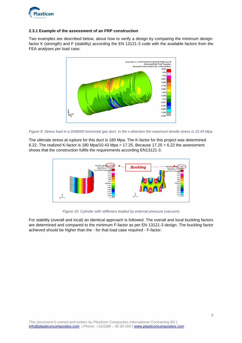
2.3.1 Example of the assessment of an FRP construction
Two examples are described below, about how to verify a design by comparing the minimum design-
factor K (strength) and F (stability) according the EN 13121-3 code with the available factors from the
FEA analyses per load case.
Figure 9: Stress load in a DN8000 horizontal gas duct. In the x-direction the maximum tensile stress is 10.43 Mpa.
The ultimate stress at rupture for this duct is 180 Mpa. The K-factor for this project was determined
6.22. The realized K-factor is 180 Mpa/10.43 Mpa = 17.25. Because 17.25 > 6.22 the assessment
shows that the construction fulfils the requirements according EN13121-3.
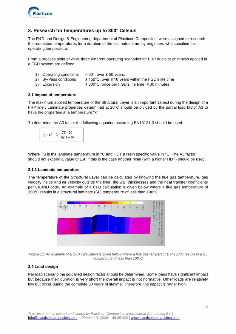
Figure 10: Cylinder with stiffeners loaded by external pressure (vacuum)
For stability (overall and local) an identical approach is followed. The overall and local buckling factors
are determined and compared to the minimum F-factor as per EN 13121-3 design. The buckling factor
achieved should be higher than the - for that load case required - F-factor.
10
This document is owned and written by Plasticon Composites International Contracting BV | [email protected] | Phone: +31(0)88 – 85 85 000 | www.plasticoncomposites.com
3. Research for temperatures up to 300° Celsius
The R&D and Design & Engineering department of Plasticon Composites, were assigned to research
the requested temperatures for a duration of the estimated time, by engineers who specified this
operating temperature.
From a process point of view, three different operating scenarios for FRP ducts or chimneys applied in
a FGD system are defined:
1) Operating conditions ≈ 60°, over ≤ 50 years.
2) By-Pass conditions ≤ 150°C, over ≤ 10 years within the FGD’s life time
3) Excursion ≤ 300°C, once per FGD’s life time, ≤ 30 minutes
3.1 Impact of temperature
The maximum applied temperature of the Structural Layer is an important aspect during the design of a
FRP liner. Laminate properties determined at 20°C should be divided by the partial load factor A3 to
have the properties at a temperature “x”
To determine the A3 factor the following equation according EN13121-3 should be used.
Where TS is the laminate temperature in °C and HDT a resin specific value in °C. The A3 factor
should not exceed a value of 1.4. If this is the case another resin (with a higher HDT) should be used.
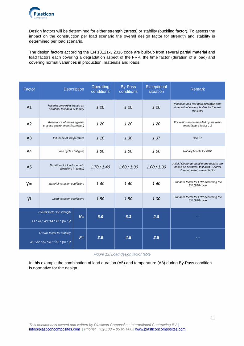
3.1.1 Laminate temperature
The temperature of the Structural Layer can be calculated by knowing the flue gas temperature, gas
velocity inside and air velocity outside the liner, the wall thicknesses and the heat transfer coefficients
per CICIND code. An example of a CFD calculation is given below where a flue gas temperature of
150°C results in a structural laminate (SL) temperature of less than 100°C.
Figure 11: An example of a CFD calculation is given below where a flue gas temperature of 150°C results in a SL temperature of less than 100°C
3.2 Load design
Per load scenario the so-called design factor should be determined. Some loads have significant impact
but because their duration is very short the overall impact is not normative. Other loads are relatively
low but occur during the complete 50 years of lifetime. Therefore, the impact is rather high.
11
This document is owned and written by Plasticon Composites International Contracting BV | [email protected] | Phone: +31(0)88 – 85 85 000 | www.plasticoncomposites.com
Design factors will be determined for either strength (stress) or stability (buckling factor). To assess the
impact on the construction per load scenario the overall design factor for strength and stability is
determined per load scenario.
The design factors according the EN 13121-3:2016 code are built-up from several partial material and
load factors each covering a degradation aspect of the FRP, the time factor (duration of a load) and
covering normal variances in production, materials and loads.
Factor Description Operating conditions
By-Pass conditions
Exceptional situation
Remark
A1 Material properties based on
historical test data or theory 1.20 1.20 1.20 Plasticon has test data available from different laboratory tested for the last
decades
A2 Resistance of resins against
process environment (corrosion) 1.20 1.20 1.20 For resins recommended by the resin
manufacture factor 1.2
A3 Influence of temperature 1.10 1.30 1.37 See 6.1
A4 Load cycles (fatigue) 1.00 1.00 1.00 Not applicable for FGD
A5 Duration of a load scenario
(resulting in creep) 1.70 / 1.40 1.60 / 1.30 1.00 / 1.00 Axial / Circumferential creep factors are
based on historical test data. Shorter duration means lower factor
Ɣm Material variation coefficient 1.40 1.40 1.40 Standard factor for FRP according the
EN 1990 code
Ɣf Load variation coefficient 1.50 1.50 1.00 Standard factor for FRP according the
EN 1990 code
Overall factor for strength
A1 * A2 * A3 *A4 * A5 * Ɣm * Ɣf
K= 6.0 6.3 2.8 - -
Overall factor for stability
A1 * A2 * A3 *A4 * √A5 * Ɣm * Ɣf
F= 3.9 4.5 2.8 - -
Figure 12: Load design factor table
In this example the combination of load duration (A5) and temperature (A3) during By-Pass condition
is normative for the design.
12
This document is owned and written by Plasticon Composites International Contracting BV | [email protected] | Phone: +31(0)88 – 85 85 000 | www.plasticoncomposites.com
4. The theory behind a high temperature
The actual theory of safety factors and standards which are described by different known and leading
engineering agencies must be compared. Experience is one, but what about the standard, how do
chimneys perform and which factors are applicable in what conditions?
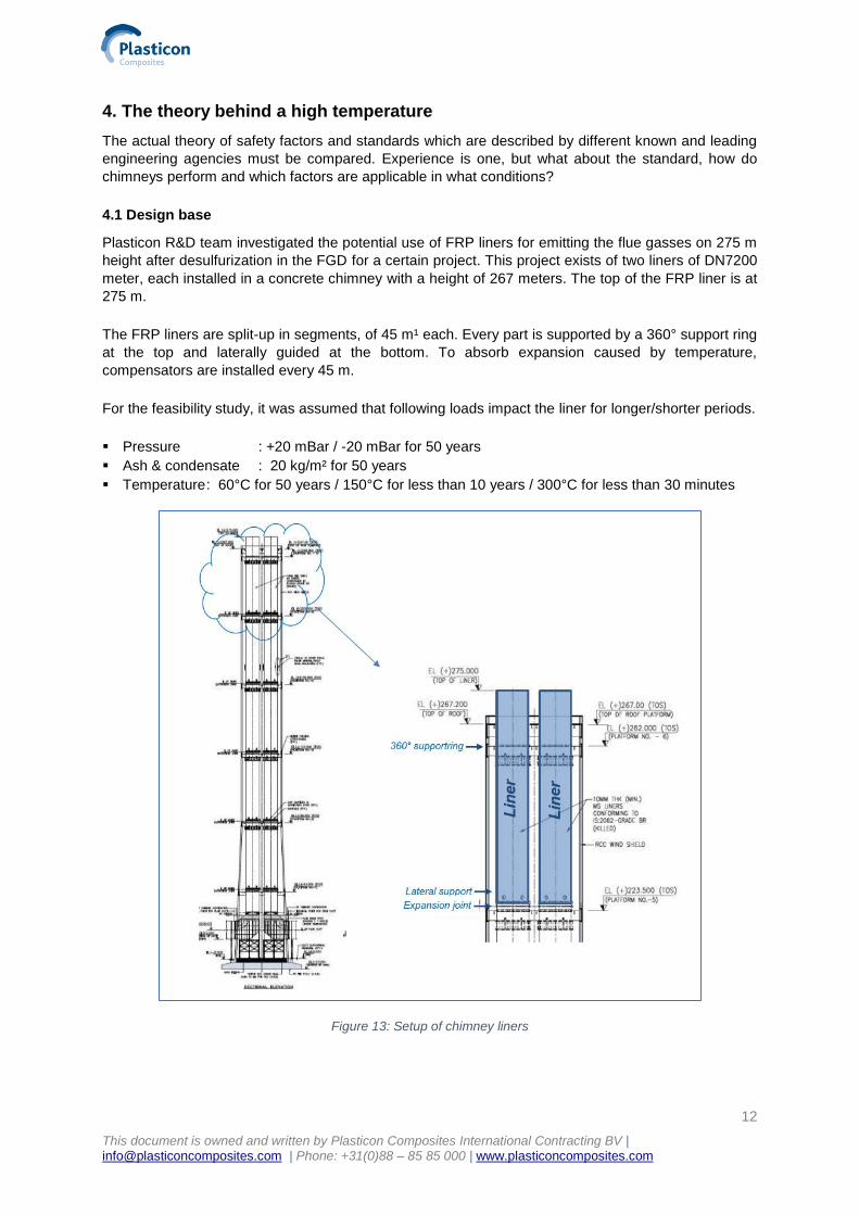
4.1 Design base
Plasticon R&D team investigated the potential use of FRP liners for emitting the flue gasses on 275 m
height after desulfurization in the FGD for a certain project. This project exists of two liners of DN7200
meter, each installed in a concrete chimney with a height of 267 meters. The top of the FRP liner is at
275 m.
The FRP liners are split-up in segments, of 45 m¹ each. Every part is supported by a 360° support ring
at the top and laterally guided at the bottom. To absorb expansion caused by temperature,
compensators are installed every 45 m.
For the feasibility study, it was assumed that following loads impact the liner for longer/shorter periods.
▪ Pressure : +20 mBar / -20 mBar for 50 years
▪ Ash & condensate : 20 kg/m² for 50 years
▪ Temperature : 60°C for 50 years / 150°C for less than 10 years / 300°C for less than 30 minutes
Figure 13: Setup of chimney liners
13
This document is owned and written by Plasticon Composites International Contracting BV | [email protected] | Phone: +31(0)88 – 85 85 000 | www.plasticoncomposites.com
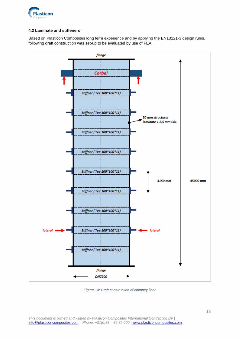
4.2 Laminate and stiffeners
Based on Plasticon Composites long term experience and by applying the EN13121-3 design rules,
following draft construction was set-up to be evaluated by use of FEA.
Figure 14: Draft construction of chimney liner
14
This document is owned and written by Plasticon Composites International Contracting BV | [email protected] | Phone: +31(0)88 – 85 85 000 | www.plasticoncomposites.com
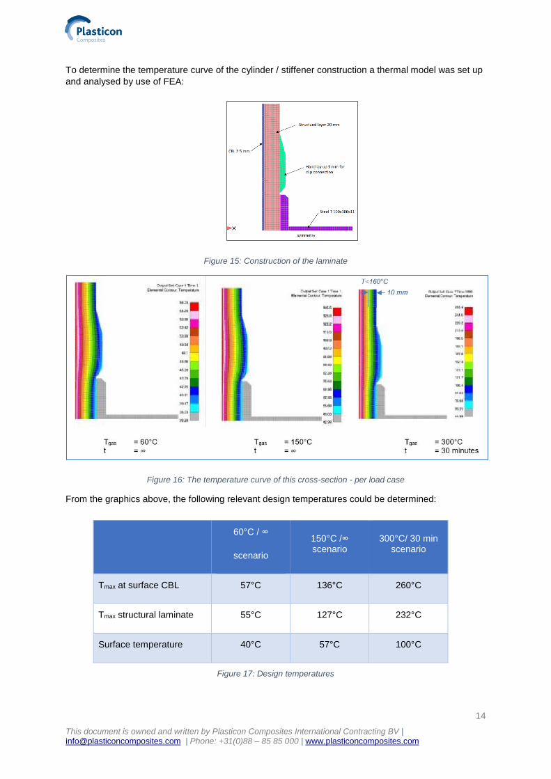
To determine the temperature curve of the cylinder / stiffener construction a thermal model was set up
and analysed by use of FEA:
Figure 15: Construction of the laminate
Figure 16: The temperature curve of this cross-section - per load case
From the graphics above, the following relevant design temperatures could be determined:
60°C / ∞
scenario
150°C /∞ scenario
300°C/ 30 min scenario
Tmax at surface CBL 57°C 136°C 260°C
Tmax structural laminate 55°C 127°C 232°C
Surface temperature 40°C 57°C 100°C
Figure 17: Design temperatures
15
This document is owned and written by Plasticon Composites International Contracting BV | [email protected] | Phone: +31(0)88 – 85 85 000 | www.plasticoncomposites.com
This would mean, that with the exceptional loading of 300°C/30 minutes, the maximum temperature of the Structural Layer is higher than the (HDT -/- 20°C) requirement according EN13121-3. Though, the temperature will decrease by moving outwards in the Structural Layer of the laminate. Eventually, the temperature will drop to a 100°C at the surface.
The detailed analyses showed that 10 mm into the structural layer the temperature is <160°C. This means that the outer 10 mm of the Structural Layer is still perfectly able to transfer loads and to resist buckling loads.
Of course, the applicable stress will be higher and the buckling factor will be lower (due to reduced “load carrying thickness”). Yet, due to the short timeframe in which this situation would occur, the calculated design factors are also significantly lower (see figure 11: Load design table).
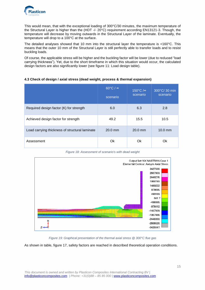
4.3 Check of design / axial stress (dead weight, process & thermal expansion)
60°C / ∞
scenario
150°C /∞ scenario
300°C/ 30 min scenario
Required design factor (K) for strength 6.0 6.3 2.8
Achieved design factor for strength 49.2 15.5 10.5
Load carrying thickness of structural laminate 20.0 mm 20.0 mm 10.0 mm
Assessment Ok Ok Ok
Figure 18: Assessment of scenario's with dead weight
Figure 19: Graphical presentation of the thermal axial stress @ 300°C flue gas
As shown in table, figure 17, safety factors are reached in described theoretical operation conditions.

16
This document is owned and written by Plasticon Composites International Contracting BV | [email protected] | Phone: +31(0)88 – 85 85 000 | www.plasticoncomposites.com
4.4 Check of design / buckling factor (from external pressure)
60°C / ∞
Scenario
150°C /∞ scenario
300°C/ 30 min scenario
Required design factor (F) for stability 3.9 4.5 2.8
Achieved design factor for strength 4.8 4.8 3.2
Load carrying thickness of structural laminate 20.0 mm 20.0 mm 10.0 mm
Assessment Ok Ok Ok
Figure 20: Assessment of scenario’s with buckling factor
Figure 21: Graphical presentation of the local and global buckling of the '10 mm load carrying cylinder’ @ 300°C flue gas
17
This document is owned and written by Plasticon Composites International Contracting BV | [email protected] | Phone: +31(0)88 – 85 85 000 | www.plasticoncomposites.com
5. Degradation of mechanical properties
In general, FRP properties will degrade less or more linear until the Tg of the resin has been reached
(Tg: glass transition temperature: the temperature when the resin loses its properties, shape and
characteristics). Above that temperature reduction will continue less linear and stabilize at 300°C finally
on a level of ± 25% of the original properties.
Over temperature the reduction of the tensile properties is less than the reduction of the flexural
properties. This has to do with the way the loads are transferred through the laminate. Due to flexural
loads shear stresses between the layers will occur. The shear strength of the resin reduces at higher
temperature. From tensile loads this type of stresses not occur so impact of temperature is less.
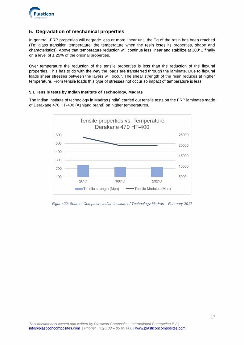
5.1 Tensile tests by Indian Institute of Technology, Madras
The Indian Institute of technology in Madras (India) carried out tensile tests on the FRP laminates made
of Derakane 470 HT-400 (Ashland brand) on higher temperatures.
Figure 22: Source: Comptech, Indian Institute of Technology Madras – February 2017
18
This document is owned and written by Plasticon Composites International Contracting BV | [email protected] | Phone: +31(0)88 – 85 85 000 | www.plasticoncomposites.com
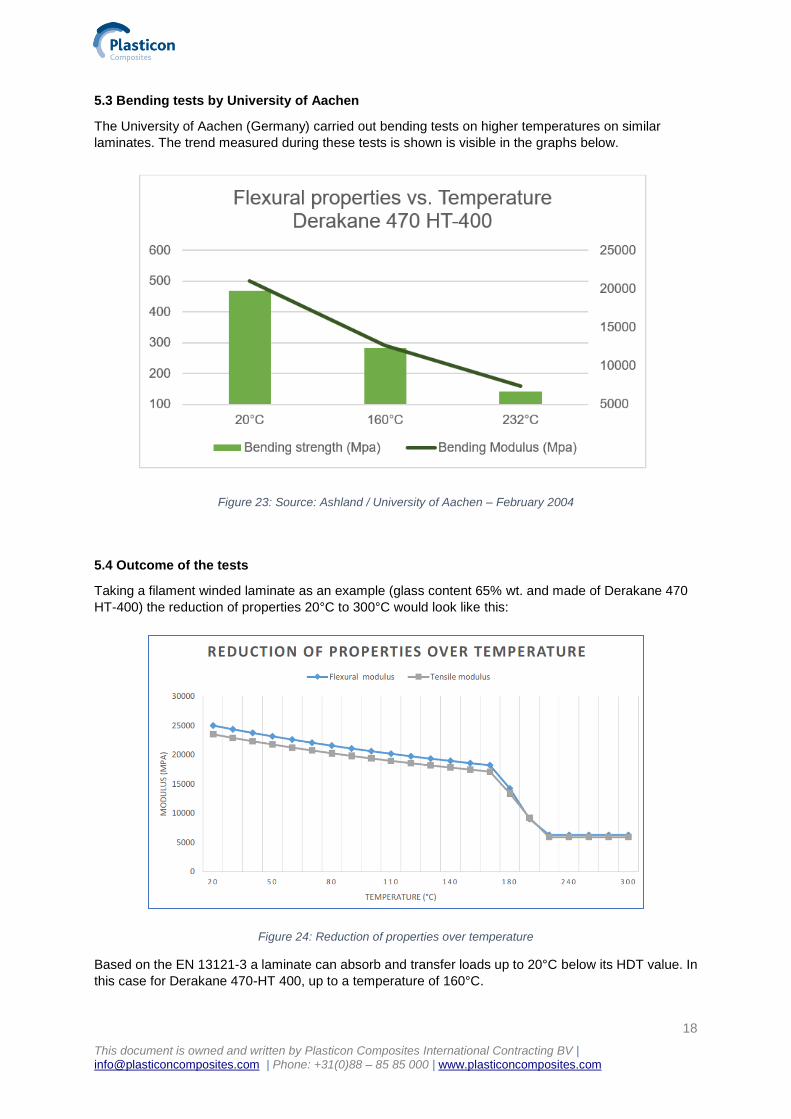
5.3 Bending tests by University of Aachen
The University of Aachen (Germany) carried out bending tests on higher temperatures on similar
laminates. The trend measured during these tests is shown is visible in the graphs below.
Figure 23: Source: Ashland / University of Aachen – February 2004
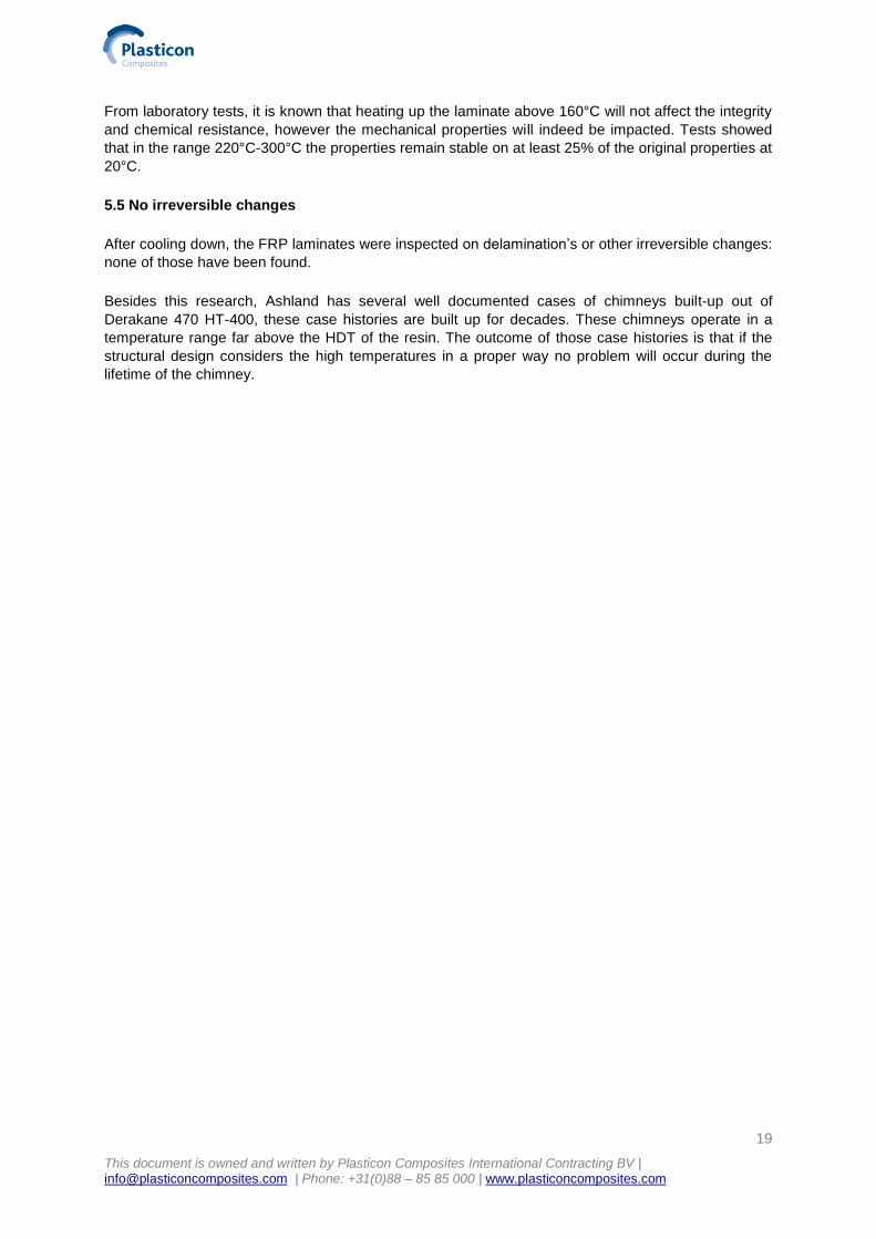
5.4 Outcome of the tests
Taking a filament winded laminate as an example (glass content 65% wt. and made of Derakane 470
HT-400) the reduction of properties 20°C to 300°C would look like this:
Figure 24: Reduction of properties over temperature
Based on the EN 13121-3 a laminate can absorb and transfer loads up to 20°C below its HDT value. In
this case for Derakane 470-HT 400, up to a temperature of 160°C.
19
This document is owned and written by Plasticon Composites International Contracting BV | [email protected] | Phone: +31(0)88 – 85 85 000 | www.plasticoncomposites.com
From laboratory tests, it is known that heating up the laminate above 160°C will not affect the integrity
and chemical resistance, however the mechanical properties will indeed be impacted. Tests showed
that in the range 220°C-300°C the properties remain stable on at least 25% of the original properties at
20°C.
5.5 No irreversible changes
After cooling down, the FRP laminates were inspected on delamination’s or other irreversible changes:
none of those have been found.
Besides this research, Ashland has several well documented cases of chimneys built-up out of
Derakane 470 HT-400, these case histories are built up for decades. These chimneys operate in a
temperature range far above the HDT of the resin. The outcome of those case histories is that if the
structural design considers the high temperatures in a proper way no problem will occur during the
lifetime of the chimney.
20
This document is owned and written by Plasticon Composites International Contracting BV | [email protected] | Phone: +31(0)88 – 85 85 000 | www.plasticoncomposites.com
6. Conclusion
For the design & engineering phase, as well as the test phase at different independent institutes in both
Europe as India, it was concluded that the exposure to a temperature of 300°C for an FRP laminate,
which is constructed with high-temperature resin and for a period of 30 minutes, would not have any
influences on performance.
The FRP laminate that is specially designed for FGD chimneys is proven to have excellent properties,
this is concluded out of different point of views:
1) FRP has proven track record in FGD applications for over 40 years with an expected life span
of 30 years.
2) FEA analysis based using internationally recognized design codes proof 300°C for a period of
30 minutes is not an issue.
3) Independent institutions concluded detailed tests on FRP laminates, that were constructed for
FGD applications. These tests show that performance of the laminates will not be affected
irreversibly in any way after the exposure to 300°C degrees for a time of 30 minutes.
Therefore it is proven that FRP ducts and chimneys can resist a short-term excursion temperature up to
300°C degrees without any permanent damages in the Structural Laminate, shape or corrosion resistant
properties or any other characteristics.
This report writes that FRP laminates and constructions would be a material that could be selected and
considered as suitable material for chimney liners, duct systems as well as bypass systems for FGD
applications. The FGD conditions differ per design and process of each power station, this challenges
engineers to analyse designs and processes and understanding key standards and case histories.
The reason why the government of India will invest in the refurbishments of coal fired power stations is
the health and safety for its people. Researching all factors and collecting information on the process
designs and constructions are key to come to a solution which offers long term solutions.
FRP chimney liners and ducts are corrosion resistant and have been proven to be a long term solution
in other regions of the world. Maintenance or repair costs have turned out, the last decades, to be
minimal compared to conventional materials. When a low cost of ownership for a construction is a reason
to select equipment for power stations, the option of FRP material is to be discussed.