fieldbus integration in simatic pcs 7 - siemens · fieldbus integration in simatic pcs 7 ......
TRANSCRIPT

SIMATIC PCS 7
Fieldbus Integration in SIMATIC PCS 7
siemens.com/simatic-pcs7
BrochureNovember2015
BR_Feldbusintegration_11_2015_en.indd 1 01.12.2015 16:46:27
© Siemens AG 2015

Compared to conventional 4-20 mA / HART technology, fieldbus architectures based on PROFIBUS PA or FOUNDATION Fieldbus H1 can achieve significant cost advantages – in design technology, assembly and wiring, as well as in planning, engineering and commissioning, and maintenance and service – over the entire life cycle of a plant. Both fieldbuses can be seamlessly integrated into the SIMATIC PCS 7 process control system with gateways, whereby topologies with active field distributors can also provide high availability in addition to high flexibility.
When you select PROFIBUS PA as the fieldbus system, you have addi-tional benefits with the innovative field distributors of Siemens. Its software will guide you to success in only 6 steps during commission-ing of the fieldbus segment. This enables you to avoid errors and start operation of the plant faster. During operation, the inte grated fieldbus diagnostics enables continuous monitoring of the PROFIBUS PA seg-ment as well as identification of field devices requiring maintenance. This supports preventive maintenance in the context of asset manage-ment and helps to avoid plant downtimes.
BR_Feldbusintegration_11_2015_en.indd 2 01.12.2015 16:46:44
© Siemens AG 2015

Distributed I/O devices such as remote I/O stations with their I/O modules, transmitters, drives, valves, operator terminals, etc., communicate with the automation systems on the field level through a powerful fieldbus system.
Since primary processes during production in the process industry are often combined with discrete sub-processes (secondary processes, inbound and outbound logistics), the demands on the fieldbus system are varied. Speed and determinism are of primary importance for discrete sub-processes. In the automation of industrial processes, how-ever, the decisive factors are availability, direct connection of intrinsically-safe devices and their power supply over the communication medium, as well as high information content of the communication.
The universal PROFIBUS can satisfy these different require-ments with supplementary transmission technologies, a uniform communication profile, and additive application profiles for typical device functions, such as PA profiles or PROFIsafe. With 50.9 million units (as of the end of 2014) including more than 9 million in the process industry, it is the most successful fieldbus worldwide.
Fieldbus systems
G_P
CS
7_X
X_0
0247
SIMATIC PCS 7 automation system
Maintenance/OS server
OS multi-clientsEngineering station
Drives PROFIBUS PA
Industrial Ethernet
FOUNDATION Fieldbus H1
PROFIBUS DP
Compact FF LinkPA Link
Remote I/O
System integration of PROFIBUS PA and FOUNDATION Fieldbus H1 via PROFIBUS DP
INTR
OD
UC
TIO
N
BR_Feldbusintegration_11_2015_en.indd 3 01.12.2015 16:46:49
© Siemens AG 2015

Technical specifications PROFIBUS PA FOUNDATION Fieldbus H1
Data transmission MBP MBP
Transmission rate 31.25 Kbps 31.25 Kbps
Cable Two-wire shielded Two-wire shielded
Type of protection Ex ia/ib/ic Ex ia/ib/ic
Topology Line, tree, ring Line, tree, ring
Safety Integrated –
Control in the field –
Interoperability
Field devices per segment/coupler 31 (typical 16 … 20) 31 (typical 8 … 10)
Field devices per link 64 31
Active field distributors per segment/coupler- AFD- AFDiSD or combinations of AFDiSD and AFD
85
85
Max. total current consumption of all field devices 1 A 0.5 A
Max. cable length per segment 1 900 m 1 900 m
PROFIBUS DP Designed for data transfer rates of up to 12 Mbps and fast response times down to 1 ms, PROFIBUS DP, which is based on the IEC 61158 and IEC 61784 standards, has proven itself in numerous projects around the world as a rugged and reliable communication medium for the field. PROFIBUS DP can be implemented in electrical or optical transmission systems, which may be redundant if required, and can be operated as an intrinsically-safe fieldbus in Ex zone 1 or 21 via a fieldbus isolating repeater. It also supports the HART protocol and is at the same time:
A communication medium for data transfer between automation systems and remote I/O stations of the ET 200 series, as well as field/process devices, drives, analyzers, CPUs/CPs, operator panels etc.
An integrator for the PROFIBUS PA fieldbus and FOUNDATION Fieldbus H1, which are typical in the process industry
PROFIBUS PA and FOUNDATION Fieldbus H1 With the PROFIBUS PA and FOUNDATION Fieldbus H1 (FF H1), two competing fieldbus systems are available for industrial processes, which often run in harsh, potentially explosive environments that could pose risks to health.
Both fieldbuses are optimally suitable for direct integration of actuators and sensors in operating environments up to Ex zone 1/21 or 0/20 into the process control system. The intrinsically-safe transmission technology MBP (Manchester Coded; Bus Powered) provides the power sup-ply to the field devices as well as digital data transmission with a constant transfer rate of 31.25 Kbps over a two-wire cable.
The bus hardware of PROFIBUS PA and FOUNDATION Fieldbus is identical to IEC 61158. Both can be integrated seamlessly in the SIMATIC PCS 7 process control system using PROFIBUS DP as a link. PROFIBUS PA and FOUNDATION Fieldbus thus benefit equally from the higher-level PROFIBUS DP architecture, which means that the SIMATIC PCS 7 process control customer is not restricted to a specific fieldbus. In keeping with the opti-mum field instrumentation, the customer can freely select the fieldbus based on the project-specific requirements, the optimum field devices used, and personal preferences.
INTR
OD
UC
TIO
N
PROFIBUS DP, PROFIBUS PA and FOUNDATION Fieldbus H1
BR_Feldbusintegration_11_2015_en.indd 4 01.12.2015 16:46:50
© Siemens AG 2015

Fieldbuses in explosive atmospheres
INTR
OD
UC
TIO
N
Typical configurations in explosive gas and dust atmospheres
Explosive atmospheresFieldbuses can also be operated in potentially explosive atmospheres when physical changes are made.
Architecture with DP/PA Coupler Ex [i] The PROFIBUS PA can be decoupled from the PROFIBUS DP using a DP/PA Coupler Ex [i] (in the PA Link or stand-alone). The DP/PA Coupler Ex [i] can be operated in environments according to Ex zone 2/22. PROFIBUS PA field devices placed in the intrinsically-safe line segment at the coupler output can be integrated in Ex zones 1/21 or 0/20 via SplitConnect taps (via spur line or directly via SplitConnect M12 outlet). This intrinsically-safe line segment meets the requirements of the Ex ia and Ex ib types of protection.
Architecture with active field distributors AFDAccording to type of protection Ex ic, AFD active field dis-tributors that can be operated in Ex zone 2/22, e.g. AFD4, AFD4 RAILMOUNT, AFD4 FM or AFD8, can integrate field devices placed in the same hazardous zone via spur lines in a PROFIBUS PA or FF H1 bus segment.
Architecture with active field distributors AFDiSDAccording to type of protection Ex ia or Ex ib, intrinsically-safe field devices in explosive atmospheres according to Ex zone 0/20 or 1/21 are integrated in bus segments of the PROFIBUS PA or FF H1 via spur lines of the active field dis-tributor AFDiSD. In addition to the spur lines, a configu-rable subsegment for 3 to 4 field devices (max. 500 m) up to zone 0/20 can also be created at terminal S1 of the AFDiSD. The AFDiSD can be installed in operating environ-ments according to Ex zone 1/21 or 2/22.
The use of AFDiSD on PROFIBUS PA offers significant advantages for fieldbus commissioning and diagnostics. To reap these benefits, AFDiSD according to type of protec-tion Ex ic can be used instead of the more economical AFD in Ex zone 2/22.
FM/UL
ATEX
ATEX
FM/UL
Zone 2 Zone 1 Zone 0
Class I Zone 2 Class I Zone 1 Class I Zone 0
Zone 22 Zone 21 Zone 20
Class II Zone 2 Class II Zone 1 Class II Zone 0
Dust
Gas
Hazardous area
1) Dust atmospheres: installation of components always in an enclosure with IP6x degree of protection
PA link with DP/PA coupler Ex [i]1)
Compact FF link or PA link withDP/PA coupler1)
SIMATIC PCS 7 automation system
Industrial Ethernet
PROFIBUS PA/FF H1 AFDiSD
PROFIBUS DP
PROFIBUS PA
G_P
CS
7_X
X_0
0147
BR_Feldbusintegration_11_2015_en.indd 5 01.12.2015 16:46:51
© Siemens AG 2015

DP/PA Coupler and PA Link
Gateways PROFIBUS PA
DP/PA Coupler When the data volume and time requirements are low, DP/PA couplers can be independently used as a gateway for PROFIBUS PA segments in a simple line or tree structure. The data transfer rate on the PROFIBUS DP is limited to 45.45 Kbps in this case.
The following coupler variants are available for this:
DP/PA Coupler Ex [i] (max. 110 mA output current) DP/PA Coupler FDC 157-0 (max. 1 000 mA output cur-
rent)
FDC 157-0 DP/PA couplers configured as PROFIBUS diag-nostics slaves with their own PROFIBUS address supply comprehensive diagnostic and status information for quick localization and correction of faults:
I&M (Identification & Maintenance) data Current and voltage values on the main line Redundancy status Wire break Short-circuit
PA Link The PA Link is the first choice for more demanding require-ments relating to the number of nodes, availability and cycle time. It supports data transfer rates on PROFIBUS DP of up to 12 Mbps.
The PA link is a modular combination in S7-300 design consisting of the IM 153-2 High Feature Outdoor interface module (with optional redundancy) and up to 5 DP/PA cou-plers (FDC 157-0 or Ex [i]). FDC 157-0 DP/PA couplers are mandatory for bus architectures with active field distributors.
To create bus segments with higher availability (line with coupler redundancy or ring with coupler and media redun-dancy), you can configure two of the up to 5 FDC 157-0 DP/PA couplers as a redundant coupler pair in a PA Link. Additional line segments to individual couplers can be operated on this PA Link.
The S7 backplane bus constructed with passive bus con-nectors or active bus modules interconnects all PA Link components. The redundant configuration of interface module and FDC 157-0 DP/PA coupler as well as changes in runtime require the use of an active bus.
PRO
FIB
US
PA
BR_Feldbusintegration_11_2015_en.indd 6 01.12.2015 16:46:51
© Siemens AG 2015

Compact FF Link single and redundant
Gateways FOUNDATION Fieldbus H1
Compact FF Link The Compact FF Link with an S7-300 design, consisting of a PROFIBUS DP interface (DPV1 slave) and a field device coupler for a subordinate FF bus segment, can be operated as a gateway either alone or redundantly in pairs. A single Compact FF Link is able to connect an FF line segment to a single PROFIBUS DP segment. With a redundant pair, how-ever, a FF line/ring segment can connect to a redundant PROFIBUS DP.
When a single Compact FF Link is used, it can be mounted directly on a standard mounting rail. When the FF segment is connected via two redundant Compact FF Links, the BM bus module installed on a mounting rail for "hot swapping" serves as a host for the Compact FF Link. This allows a Compact FF Link to be replaced during runtime.
FOU
ND
ATI
ON
FIE
LDB
US
H1
Highlights Compact FF Link
Lower space requirements- 40 mm instead of 120 mm single- 80 mm instead of 240 mm redundantThis allows additional Compact FF Links to be installed in the control cabinet, meaning that fewer control cabi-nets are required.
Extended temperature range of -40 to +70° C, allowing distributed use of Compact FF Links
HIST Class 61b certified system
BR_Feldbusintegration_11_2015_en.indd 7 01.12.2015 16:46:55
© Siemens AG 2015

Active field distributors
With conventional fieldbus installations, changes during runtime are only possible to a very limited extent. Extreme caution is necessary when connecting new devices. Short-circuits or bouncing of the connections during installation can result in failure of the complete segment.
Fieldbus installations with active field distributors from SIMATIC offer many more possibilities with regard to modi-fications and availability, particularly in a ring architecture:
Automatic termination Support for a ring architecture Status LED on enclosure Short-circuit-proof spur lines Detection of short-circuits and cable breaks Detection of chatter
These features enable you to add/remove field devices and AFDs in runtime without repercussions.
The total length of such a fieldbus segment can be up to 1 900 m. Up to 31 field devices per fieldbus segment can be integrated via active field distributors AFD, e.g. AFD4, AFD4 RAILMOUNT, AFD4 FM or AFD8 and AFDiSD.
Alternatively, it is possible to operate up to 8 AFD field distributors, up to 5 AFDiSD field distributors or any com-bination of up to 5 AFDiSD and AFD field distributors in a fieldbus segment. The spur lines for connecting the devices to the active field distributors can be up to 120 m long according to IEC 61158-2 and up to 60 m according to IEC 60079-27 (intrinsically safe according to FISCO). The maximum length of 120 m may be reduced with AFD active field distributors depending on the total number of spur lines of the bus segment. With AFDiSD active field dis-tributors, this is not the case due to the integrated repeater function.
Active field distributor AFD4 RAILMOUNT (left) and AFD4 (right)
AC
TIV
E FI
ELD
DIS
TRIB
UTO
RS
BR_Feldbusintegration_11_2015_en.indd 8 01.12.2015 16:47:07
© Siemens AG 2015
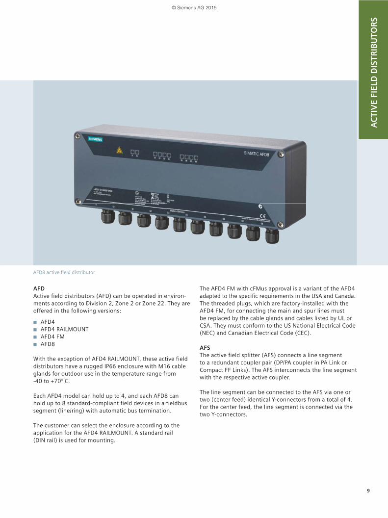
AFDActive field distributors (AFD) can be operated in environ-ments according to Division 2, Zone 2 or Zone 22. They are offered in the following versions:
AFD4 AFD4 RAILMOUNT AFD4 FM AFD8
With the exception of AFD4 RAILMOUNT, these active field distributors have a rugged IP66 enclosure with M16 cable glands for outdoor use in the temperature range from -40 to +70° C.
Each AFD4 model can hold up to 4, and each AFD8 can hold up to 8 standard-compliant field devices in a fieldbus segment (line/ring) with automatic bus termination.
The customer can select the enclosure according to the application for the AFD4 RAILMOUNT. A standard rail (DIN rail) is used for mounting.
The AFD4 FM with cFMus approval is a variant of the AFD4 adapted to the specific requirements in the USA and Canada. The threaded plugs, which are factory-installed with the AFD4 FM, for connecting the main and spur lines must be replaced by the cable glands and cables listed by UL or CSA. They must conform to the US National Electrical Code (NEC) and Canadian Electrical Code (CEC).
AFSThe active field splitter (AFS) connects a line segment to a redundant coupler pair (DP/PA coupler in PA Link or Compact FF Links). The AFS interconnects the line segment with the respective active coupler.
The line segment can be connected to the AFS via one or two (center feed) identical Y-connectors from a total of 4. For the center feed, the line segment is connected via the two Y-connectors.
AFD8 active field distributor
AC
TIV
E FI
ELD
DIS
TRIB
UTO
RS
BR_Feldbusintegration_11_2015_en.indd 9 01.12.2015 16:47:20
© Siemens AG 2015

AFDiSD active field distributor
AFDiSD active field distributor
AFDiSDAFDiSDs (Active field distributors intrinsically-safe with extended fieldbus diagnostics for PROFIBUS PA segments) can be operated in environments according to Ex zone 1/21 and 2/22. They have the following features:
Rugged IP66 enclosure for outdoor use Temperature range from -40 to +70 °C Cable gland (main line M20, spur line M16)
AFDiSDs can integrate up to 6 standard-compliant intrinsi-cally-safe field devices in a fieldbus segment (line/ring) via its intrinsically-safe, short-circuit proof spur line connec-tions. A subsegment for 3 to 4 devices with a max. length of 500 m at connection S1 can be operated instead of the spur line. The spur lines and the subsegment can also be installed in Ex zone 0/20.
AFDiSD highlights
Integrated power management at startup
Integrated circuit repeater (signal processing, segmentation)
System-guided commissioning
Increased productivity and reduced downtimes
Increased flexibility
Cost savings
AC
TIV
E FI
ELD
DIS
TRIB
UTO
RS
BR_Feldbusintegration_11_2015_en.indd 10 01.12.2015 16:47:29
© Siemens AG 2015

Extended PROFIBUS PA diagnostics
Extended PROFIBUS PA diagnosticsAFDiSD standard diagnostics is limited to short-circuits, loss of redundancy, detection of chatter, and failure of field devices. Using a mode selector on the AFDiSD, the functionality can be extended for PROFIBUS PA with a com-missioning wizard, continuous operational monitoring and support for troubleshooting. This enables comprehensive diagnostics of the entire PROFIBUS PA segment. Errors in the configuration or defects can thus be quickly identified and remedied. However, this requires all active field dis-tributors of the segment as well as the components of the PA Link to support the extended diagnostics functionality.
Extended PROFIBUS PA diagnostics enables identification, detection and monitoring of:
Topology (DP/PA coupler, AFDiSD) Voltage and current on the main and spur lines Signal and noise levels (e.g. noise and jitter) Capacitive imbalance to the shield of the main line
The interface module of the PA Link creates a topology model of the connected bus segment, and maps its status information. The DP/PA coupler and the locally installed active field distributor AFDiSD provide the interface mod-ule with the physical data of the bus segment for this pur-pose, as well as information on the status of the connected lines. The information provided by the interface module can be displayed and evaluated on the SIMATIC PCS 7 Maintenance Station and SIMATIC PDM.
The use of SIMATIC AFDiSD enables system-guided and simpler addressing of the PROFIBUS PA field devices. Furthermore, PROFIBUS PA spur lines can be conveniently enabled and disabled remotely.
Physical layer data
AC
TIV
E FI
ELD
DIS
TRIB
UTO
RS
Highlights
Measurement takes place at the point at which the event occurs
Full integration in the SIMATIC PCS 7 workflow Preventive maintenance: AFDiSD brings transparency
to fieldbus installation
Status of main line (input T1)- Detection of short-circuit/cable break- Detection of voltage setpoint / actual value- Detection of current setpoint / actual value
If the actual value is outside the warning and alarm range of the respective values, the status is displayed accordingly.
Status of main line (output T2)- Detection of short-circuit/cable break- Detection of voltage setpoint / actual value- Detection of current setpoint / actual value
General signal state- Signal level setpoint / actual value- Signal asymmetry setpoint / actual value- Signal noise setpoint / actual value- Signal jitter setpoint / actual value
BR_Feldbusintegration_11_2015_en.indd 11 01.12.2015 16:47:37
© Siemens AG 2015

Commissioning wizard6 steps to success!
Provision/loading current data of the fieldbus components
Automatic detection and activation of the spur line of the field device including status display and system support for address assignment of PROFIBUS PA field devices
Definition of specifications for the fieldbus seg-ment, e.g. alarm and warning limits (by the system or by the user)
Summary with current status of the commissioning, access to extended diagnostic data, export function for archiving and long-term evaluation as well as generation of a com-missioning report
Entering identification and maintenance data
Scanning and visualization of the fieldbus topology
Commissioning wizardAs an integral part of the extended PROFIBUS PA diagnostics, the commissioning wizard is able to analyze and archive the physical data of the PROFIBUS PA segment for installation and maintenance, and to define limits for preventive maintenance. It can be used to significantly simplify and rationalize commis-
sioning. It guides the user in a few steps through commission-ing and maintenance of a PROFIBUS PA installation.
AC
TIV
E FI
ELD
DIS
TRIB
UTO
RS
BR_Feldbusintegration_11_2015_en.indd 12 01.12.2015 16:47:37
© Siemens AG 2015

ArchitecturesSIMATIC Fieldbus Calculator
The design requirements for the fieldbus segments consist of the optimum combination of application area, scaling and topology. It is important to observe physical and sys-tem-related stipulations and restrictions in this regard.
The SIMATIC Fieldbus Calculator provides help in designing and calculating fieldbus segments: https://support.industry.siemens.com/cs/ww/en/view/53842953
Scope of SIMATIC Fieldbus Calculators:
Flexible design of fieldbus segments, changing cable lengths, relocating field devices
Information on limit violations of individual electrical variables
Analysis and expansion of existing configurations
AR
CH
ITEC
TUR
ES
BR_Feldbusintegration_11_2015_en.indd 13 01.12.2015 16:47:40
© Siemens AG 2015

AR
CH
ITEC
TUR
ES
PROFIBUS PA at an AS single station / AS redundancy station as PROFIBUS DP master
The PROFIBUS PA is integrated in SIMATIC PCS 7 via PROFIBUS DP. The PROFIBUS PA installations possible depend on whether PROFIBUS DP master and PROFIBUS DP are configured single or redundant.
Linear architecture with single couplerIn the line architecture with single couplers, each line seg-ment is connected to one DP/PA coupler. If the PA gateway is an independent DP/PA coupler, a single line segment can be connected to it. A maximum of 5 line segments can be operated via sin-gle couplers (max. 3 for mixed configurations with ring or coupler redundancy) on a PA Link. By grouping individual devices in different line segments, Flexible Modular Redun-dancy is possible on the device level.
The FDC 157-0 is the first choice for a DP/PA coupler. When this coupler is used, the PA devices can be integrated into the line segment via the active field distributors AFD (approval for Ex zone 2/22) and AFDiSD (approval for Ex zone 1/21). The last field distributor at the end of the line leading away from the DP/PA coupler automatically activates its bus terminating resistor.
Line architecture with redundant couplerThe PA Link operable as a PA gateway on a single or redun-dant PROFIBUS DP can only be equipped with one redun-dant DP/PA coupler pair (up to 3 single couplers can be optionally configured in addition). The redundant DP/PA coupler pair can be used either for a line architecture with active field splitter (AFS) or for a ring architecture.
With a line architecture, the AFS is connected to the redun-dant DP/PA coupler pair (2 × FDC 157-0) in the PA gateway. It interconnects the line segment connected to it to the active DP/PA coupler of the redundant pair. A DP/PA coupler can be replaced without interrupting ongoing operation.
Ring architecture with coupler and media redundancyWith the redundant DP/PA coupler pair (2 × FDC 157-0) of a PA gateway, a ring segment with automatic bus termina-tion can also be implemented instead of a line segment with AFS. Apart from the ring segment, only line segments with individual couplers can be configured on this PA gateway. The PA gateway can be connected to a single or a redundant PROFIBUS DP.
Examples of PROFIBUS PA architectures
G_P
CS
7_X
X_0
0527
SIMATIC PCS 7 automation system(AS Single Station)
DP/PA coupler in PA Link or separately
DP/PA coupler pair in PA Link
DP/PA coupler pair in PA Link
Active field distributors
Active field distributors
Active field distributors
AFS
PROFIBUS PA
PROFIBUS PA
PROFIBUS PA
PR
OFI
BU
S D
P
G_P
CS
7_X
X_0
0146
SIMATIC PCS 7 automation system(AS Redundancy Station)
DP/PA coupler in PA Link
DP/PA coupler pair in PA Link
DP/PA coupler pair in PA Link
Active field distributors
Active field distributors
Active field distributors
AFS
PROFIBUS PA
PROFIBUS PA
PROFIBUS PA
PR
OFI
BU
S D
P
BR_Feldbusintegration_11_2015_en.indd 14 01.12.2015 16:47:43
© Siemens AG 2015

Examples of FOUNDATION Fieldbus H1 architectures
FOUNDATION Fieldbus H1 on an AS single station/AS redundancy station as PROFIBUS DP master
AR
CH
ITEC
TUR
ES
When FOUNDATION Fieldbus H1 (FF H1) is integrated in the SIMATIC PCS 7 process control system, PROFIBUS DP acts as a link. The FF H1 installations possible depend on whether PROFIBUS DP master and PROFIBUS DP are config-ured single or redundant.
Accordingly, the gateway between PROFIBUS DP and FOUNDATION Fieldbus H1 is formed by a single Compact FF Link or a redundant Compact FF Link pair. An FF fieldbus segment can be operated at each gateway.
Line architecture with single Compact FF LinkA line segment can be connected to an individual PROFIBUS DP line via a Compact FF Link. The FF field devices can be integrated into the line segment via the active field distributors AFD (approval for Ex zone 2/22) and AFDiSD (approval for Ex zone 1/21). The last field distributor at the end of the line farthest away from the Compact FF Link automatically activates its bus terminat-ing resistor.
Line architecture with redundant Compact FF LinksA line segment on the AFS (active field splitter) can be connected to a redundant PROFIBUS DP via a redundant Compact FF Link pair. The AFS connected to both Compact FF Links interconnects the line segment connected to it with the active Compact FF Link in each case. A Compact FF Link can be replaced without interrupting ongoing operation.
Ring architecture with redundant Compact FF LinksThe highest availability can be achieved with a FOUNDATION Fieldbus H1 ring segment, which can be con-nected to redundant PROFIBUS DP via a redundant Com-pact FF Link pair. The bus is terminated automatically and is immediately adapted in the event of changes or faults on the bus.
G_P
CS
7_X
X_0
0528
SIMATIC PCS 7 automation system (AS Single Station)
Active field distributors
FOUNDATION Fieldbus H1
PR
OFI
BU
S D
P
Compact FF Link
SIMATIC PCS 7 automation system (AS Redundancy Station)
Active field distributors
Active field distributors
AFS
FOUNDATION Fieldbus H1
FOUNDATION Fieldbus H1P
RO
FIB
US
DP
Compact FF Link
Compact FF Link
G_P
CS
7_X
X_0
0284
BR_Feldbusintegration_11_2015_en.indd 15 01.12.2015 16:47:44
© Siemens AG 2015

The information provided in this brochure contains merely general descriptions or characteristics of performance which in case of actual use do not always apply as described or which may change as a result of further development of the products. An obligation to provide the respective characteristics shall only exist if expressly agreed in the terms of contract. Availability and technical specifications are subject to change without notice.All product designations may be trademarks or product names of Siemens AG or supplier companies whose use by third parties for their own purposes could violate the rights of the owners.
Siemens AGProcess Industries and DrivesAutomation and Engineering76181 KARLSRUHEGERMANY
Subject to change without prior noticeArticle no. E86060-A4678-A271-A2-7600W-FPN16-PD-PA236 / Dispo 09508BR 1115 2. PES 16 EnPrinted in Germany © Siemens AG 2015
www.siemens.com/automation
Security information
Siemens offers products and solutions with industrial security functions which support the secure operation of plants, solutions, machines, devices and/or networks. They are important components in a holistic industrial security concept. With this in mind, Siemens’ products and solutions undergo continuous development. Siemens recommends strongly that you regularly check for product updates.
For the secure operation of Siemens products and solutions, it is necessary to take suitable preventive action (e.g. cell protection concept) and integrate each component into a holistic, state-of-the-art industrial security concept. Third-party products that may be in use should also be considered. For more information about industrial security, visit: www.siemens.com/industrialsecurity
In order to keep yourself informed about product updates, we recommend subscribing to our product-specific newsletter. For additional information, refer to:support.industry.siemens.com
BR_Feldbusintegration_11_2015_en.indd 16 01.12.2015 16:47:45
© Siemens AG 2015