figure 1710 flow data - nibco.com
TRANSCRIPT

Figure 1710Flow Data
A H E A D O F T H E F L O W ™
C i r c u i t B a l a n c i n g Va l v e

NIBCO INC. WORLD HEADQUARTERS • 1516 MIDDLEBURY ST. • ELKHART, IN 46516-4740 • USA • PH: 1.800.234.0227 TECH SERVICES PH: 1.888.446.4226 • FAX: 1.800.234.0557 • INTERNATIONAL SERVICE PH: +1.574.295.3221 • FAX: +1.574.295.3455
www.nibco.com
2
Engineering Data
The NIBCO Commercial Valve Line is one ofthe most highly specified mechanical serv-ice Quarter-Turn and Multi-turn lines in usetoday. Specifying Engineers recognizeNIBCO Valves by name and figure numberand have made them the choice in buildingservice and general utility service applica-tions. This versatile valve line is specifiedworld wide in applications such as:
• Hot and Cold Water
• Condenser and Chilled Water
• Hot Water Heating
• Low & Medium Pressure Steam
• Fire Protection
• Compressed Air and Gas
• Vacuum
• Natural Gas Systems
• Medical Gas Systems
Why Engineers Specify NIBCO Valves:
• Multiple Design Options
• Ball Valves
• Butterfly Valves
• Gate Valves
• Globe Valves
• Check Valves
• Circuit Balancing Valves
• Actuators & Controls
• Constructed of High Quality Materials
• ISO Registered Manufacturing Plants
• Well Trained Factory Direct Sales Force
• Leader in “e-Commerce”
Why balance your system?
Whether a system is designed for heating or chilling it must be properlyadjusted and balanced for optimum design performance. An unbal-anced system will produce temperature variations of up to 14°Fbetween rooms which can typically add 35% to energy costs.
Engineers save valuable time and money when the system they areinstalling matches a pre-determined design and if accurate pressuredrop calculations have already been made.
The concept of proportional balancing
Balancing is dependent upon two basic principles:
I The adjustment of a valve in a sub-circuit alters the flow not only inthe sub-circuit but also in other circuits within the system. If suchan adjustment reduces the flow in the sub-circuit then the flowelsewhere must increase. By such means the flow through parallelcircuits may be adjusted so that the proportion of design flow isequalized.
II If water flows through a pipe which has a number of branches thenthe percentage of the total flow in each branch remains constantirrespective of how the total mass flow alters.
By the use of these principles a circuit can be adjusted so that eachsub-circuit receives its design flow rate within acceptable tolerances.
The benefits to the client of system balancing
• A balanced system ensures a comfortable indoor climate.
• The correct flow in boilers and chillers.
• The desired flow distribution throughout the building.
• Energy savings - and thereby cost savings.
• Trouble-free operation and ease of maintenance.
• Lower capital costs.

Engineering Data
NIBCO INC. WORLD HEADQUARTERS • 1516 MIDDLEBURY ST. • ELKHART, IN 46516-4740 • USA • PH: 1.800.234.0227 TECH SERVICES PH: 1.888.446.4226 • FAX: 1.800.234.0557 • INTERNATIONAL SERVICE PH: +1.574.295.3221 • FAX: +1.574.295.3455
www.nibco.com3
Circuit Balancing ValveTypical Specifications
Manual Circuit Balancing Valves installed in DomesticHot Water Service
Circuit Balancing Valves 1/2" to 2" for domestic hot water serviceshall be NIBCO Globe Style, Series 1710 or approved equal. Valveshall have integral metering/test ports for flow balancing and flowmeasurement. Test ports shall have internal check valve and beequipped with caps. Valves shall be manufactured from dezincifica-tion resistant brass or bronze rated 240 psi at 250°F. All balancingvalves shall have position indication readout and built in memorystop for repeatable regulation and control.
Manual Circuit Balancing Valves installed on Fan CoilUnits
Circuit Balancing Valves 1/2" to 3/4" to be installed on fan coil unitsshall be NIBCO Figure S1709 with solder end connections orapproved equal. Valve shall be globe style of dezincification resist-ant brass or bronze alloy. All valves shall have two integral meter-ing/test ports with internal check valves and protective caps. Thevalves must be equipped with visual position readout and memorystop for repeatable regulation and control.
Manual Circuit Balancing Valves installed in HVACSystems
Circuit Balancing Valves for heating and chilled water service shallbe based on NIBCO Figure 1710, 1/2" to 2" and NIBCO Figure 737 2"to 12" or approved equal. 1/2" to 2" valves shall be constructed ofdezincification resistant brass or bronze alloy. 2" to 12" valves willbe constructed of iron with ANSI Class 125/150 flanged or groovedends. All valves shall be globe style for precise regulation and con-trol and rated 175 psi for iron and 240 psi for bronze at 250°F. Eachvalve shall have two metering/test ports with internal check valvesand protective caps. All valves must be equipped with visual posi-tion readout and memory stop for repeatable regulation and control.
DZR Metal
Dezincification of duplex brass, which is a form of corrosion, mayoccur when in contact with certain aggressive waters.
Dezincification is the selective attack, by electrolytic corrosion, of thezinc rich beta phase in duplex brasses and is characterized by aporous coppery appearance.
To overcome the problem special copper alloys, which contain aninhibitor and undergo heat treatment, have been developed whichare resistant to corrosion by dezincification.
These materials are known as DZR or DZR metal.
A Comparison of Throttling Characteristics — Why Choose NIBCO
These curves illustrate the advantages of multi-turn adjustment available with all NIBCO Fig.1710 balancing valves.
A quarter turn 90° open valve would require a15° change in adjustment to result in a 30%change in flow measurement.
A one turn 360° open valve would require a 96°change in adjustment to result in a 30% changein flow measurement.
All NIBCO Fig. 1710 valves would require a mini-mum of 502° change in adjustment to result in a30% change in the flow measurement.

NIBCO INC. WORLD HEADQUARTERS • 1516 MIDDLEBURY ST. • ELKHART, IN 46516-4740 • USA • PH: 1.800.234.0227 TECH SERVICES PH: 1.888.446.4226 • FAX: 1.800.234.0557 • INTERNATIONAL SERVICE PH: +1.574.295.3221 • FAX: +1.574.295.3455
www.nibco.com
4
Engineering Data
Pressure/Temperature Rating
240 psi to 250°F300 psi from -20°F to 150°F
Test Pressures (Hydraulic)
Shell: 450 psiSeat: 330 psi
Specification
Non-rising stemScrewed bonnetParabolic regulating diskDouble regulating (memory stop) deviceFlow measurement accuracy
Full open ±5%25% open ±10%
Supplied fitted with two DuSeal testpoints (Fig. 631) which accept commercialpressure and temperature probes.End connections threaded to ANSI B1.20(NPT) and solder end to ANSI B16.18
Options
Drain PlugExtended test pointsPre-formed insulation
DZR Balancing ValvesFig. T1710 - S1710
Component MaterialHandwheel Polymer
Isolating Stem DZR Metal
Stem Seals EPDM
Regulating Stem DZR Metal
Bonnet DZR Metal
Disk Nut DZR Metal
Disk Seat Ring DZR Metal
Disk O-Ring EPDM
Body DZR Metal
Nominal Size A B C Weight
in. mm in. mm in. mm in. mm lb. kg
1/2 15 4 100 37/8 97 23/4 70 1.7 0.773/4 20 4 100 37/8 97 23/4 70 2.0 0.911 25 43/4 120 41/4 107 23/4 70 3.1 1.41
11/4 32 51/2 140 43/8 112 23/4 70 4.2 1.9111/2 40 57/8 150 43/8 112 33/4 95 5.1 2.322 50 61/2 165 53/8 136 33/4 95 8.0 3.64
Dimensions
Material Specifications

Engineering Data
NIBCO INC. WORLD HEADQUARTERS • 1516 MIDDLEBURY ST. • ELKHART, IN 46516-4740 • USA • PH: 1.800.234.0227 TECH SERVICES PH: 1.888.446.4226 • FAX: 1.800.234.0557 • INTERNATIONAL SERVICE PH: +1.574.295.3221 • FAX: +1.574.295.3455
www.nibco.com5
Notes: 1)Cv = Cvs = where Q = flow rate in USgpmand = head loss for Cv and signal for Cvs in psi
Valve Position
Figure 1710 Cv/Cvs Values
QP
P
25% OpenPosition
Key
ParabolicDisc
BonnetSeal
BonnetAssembly
RetainingScrew
HandwheelAssembly
MemoryStop
Test Point
Body
ValveSize (in) 1.5 1.75 2.0 2.25 2.5 3.0 3.5 4.0 4.5 5.0 5.5 6.0 7.0 8.0 9.0
1/2 0.76 0.87 0.98 1.16 1.34 13.84 2.40 2.90 3.42 3.84 4.10 4.30
3/4 1.02 1.17 1.33 1.61 1.90 2.68 3.69 4.82 5.80 6.60 7.31 8.06
1 2.10 2.37 3.14 4.00 4.98 6.06 7.9 8.10 8.92 10.40 11.83 13.55
11/4 3.64 4.23 4.80 6.15 7.66 9.38 11.13 13.18 15.16 17.18 20.44 23.99
11/2 2.10 2.62 3.14 4.59 6.27 8.20 10.37 12.91 15.71 18.76 24.57 29.10
2 5.51 6.58 7.91 9.25 12.37 16.14 20.74 26.60 31.77 36.24 40.70 43.30
√
NIBCO INC. WORLD HEADQUARTERS • 1516 MIDDLEBURY ST. • ELKHART, IN 46516-4740 • USA • PH: 1.800.234.0227 TECH SERVICES PH: 1.888.446.4226 • FAX: 1.800.234.0557 • INTERNATIONAL SERVICE PH: +1.574.295.3221 • FAX: +1.574.295.3455
www.nibco.com
6
Engineering Data
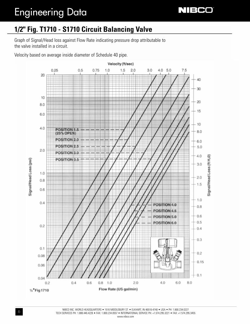
1/2" Fig. T1710 - S1710 Circuit Balancing ValveGraph of Signal/Head loss against Flow Rate indicating pressure drop attributable tothe valve installed in a circuit.
Velocity based on average inside diameter of Schedule 40 pipe.

Engineering Data
NIBCO INC. WORLD HEADQUARTERS • 1516 MIDDLEBURY ST. • ELKHART, IN 46516-4740 • USA • PH: 1.800.234.0227 TECH SERVICES PH: 1.888.446.4226 • FAX: 1.800.234.0557 • INTERNATIONAL SERVICE PH: +1.574.295.3221 • FAX: +1.574.295.3455
www.nibco.com7
3/4" Fig. T1710 - S1710 Circuit Balancing ValveGraph of Signal/Head loss against Flow Rate indicating pressure drop attributable tothe valve installed in a circuit.
Velocity based on average inside diameter of Schedule 40 pipe.

NIBCO INC. WORLD HEADQUARTERS • 1516 MIDDLEBURY ST. • ELKHART, IN 46516-4740 • USA • PH: 1.800.234.0227 TECH SERVICES PH: 1.888.446.4226 • FAX: 1.800.234.0557 • INTERNATIONAL SERVICE PH: +1.574.295.3221 • FAX: +1.574.295.3455
www.nibco.com
8
Engineering Data
1" Fig. T1710 - S1710 Circuit Balancing ValveGraph of Signal/Head loss against Flow Rate indicating pressure drop attributable tothe valve installed in a circuit.
Velocity based on average inside diameter of Schedule 40 pipe.

Engineering Data
NIBCO INC. WORLD HEADQUARTERS • 1516 MIDDLEBURY ST. • ELKHART, IN 46516-4740 • USA • PH: 1.800.234.0227 TECH SERVICES PH: 1.888.446.4226 • FAX: 1.800.234.0557 • INTERNATIONAL SERVICE PH: +1.574.295.3221 • FAX: +1.574.295.3455
www.nibco.com9
11/4" Fig. T1710 - S1710 Circuit Balancing ValveGraph of Signal/Head loss against Flow Rate indicating pressure drop attributable tothe valve installed in a circuit.
Velocity based on average inside diameter of Schedule 40 pipe.

NIBCO INC. WORLD HEADQUARTERS • 1516 MIDDLEBURY ST. • ELKHART, IN 46516-4740 • USA • PH: 1.800.234.0227 TECH SERVICES PH: 1.888.446.4226 • FAX: 1.800.234.0557 • INTERNATIONAL SERVICE PH: +1.574.295.3221 • FAX: +1.574.295.3455
www.nibco.com
10
Engineering Data
11/2" Fig. T1710 - S1710 Circuit Balancing ValveGraph of Signal/Head loss against Flow Rate indicating pressure drop attributable tothe valve installed in a circuit.
Velocity based on average inside diameter of Schedule 40 pipe.
Engineering Data
NIBCO INC. WORLD HEADQUARTERS • 1516 MIDDLEBURY ST. • ELKHART, IN 46516-4740 • USA • PH: 1.800.234.0227 TECH SERVICES PH: 1.888.446.4226 • FAX: 1.800.234.0557 • INTERNATIONAL SERVICE PH: +1.574.295.3221 • FAX: +1.574.295.3455
www.nibco.com11
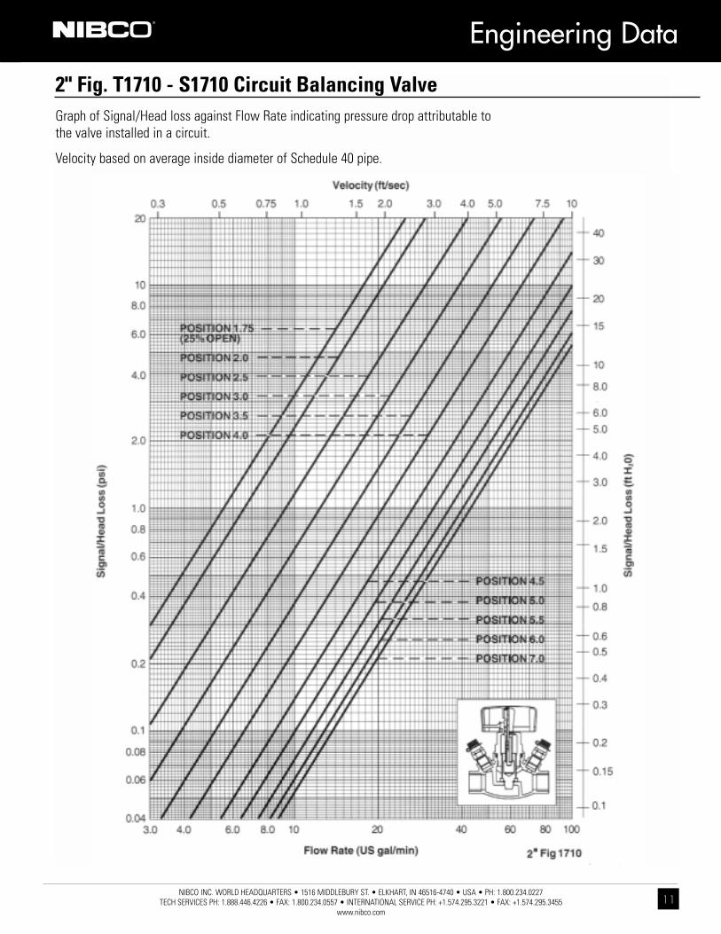
2" Fig. T1710 - S1710 Circuit Balancing ValveGraph of Signal/Head loss against Flow Rate indicating pressure drop attributable tothe valve installed in a circuit.
Velocity based on average inside diameter of Schedule 40 pipe.

N I B C O I N C .
W O R L D H E A D Q U A R T E R S
W E B : w w w . n i b c o . c o m
1 5 1 6 M I D D L E B U R Y S T R E E T
E L K H A R T, I N 4 6 5 1 6 - 4 7 4 0
U S A
D O M E S T I C C U S T O M E R S E R V I C E
P H O N E : 8 0 0 . 2 3 4 . 0 2 2 7
F A X : 8 0 0 . 2 3 4 . 0 5 5 7
T E C H N I C A L S E R V I C E
P H O N E : 8 8 8 . 4 4 6 . 4 2 2 6
F A X : 8 8 8 . 3 3 6 . 4 2 2 6
I N T E R N A T I O N A L S E R V I C E
P H O N E : + 1 / 5 7 4 . 2 9 5 . 3 2 2 1
F A X : + 1 / 5 7 4 . 2 9 5 . 3 4 5 5