final presentation murray state university industry mentor
TRANSCRIPT

Final PresentationMurray State University
Staff Advisor – Roger RiquelmeIndustry Mentor - Joshua Scarbrough
04/07/2021
Team Members
Roger Riquelme
Team Advisor
Instructor Murray
Team Members
Nate Heady
ElectroMechanical
Senior
Dami Ogunjimi
Electromechanical Engineering Tech
Sophomore
Team Members
Carson Elliott
ElectroMechanical
Junior
Problem Statement
To design a hydraulic bike that is driven
solely on human power through the use of
fluid power components in a reasonably safe
manner.
Design Goals
• Redesign steering of the vehicle
• Optimize the accumulator circuit
• Regear the Human Powered circuit for a
Higher Pressure/Lower Flow Rate system
• Integrate and properly utilize a pneumatic
system
• Redesign power input
• Integrate Electronics
• Minimize custom fabrication
Winning Tactics: Sprint Race
• Make efficient use of our stored potential
energy– Minimize coasting
– Use all energy before crossing the finish
line
• Control our acceleration via gear ratios
and timing– Multi Speed gear box
• Allow for max flow rate with the D03
Winning Tactics:Efficiency and Lap Race
• Keep the system pressure above 1700 psi
to maximize efficiency
• Make use of our 2 speed gearbox and
clutch system– Disengaging the clutch allows us to coast after
discharging the fluid in the accumulator
– The 2 speed gearbox allows us to easily
charge up potential energy after the initial
discharged
– Freewheel (ratchet) on the human powered
side prevents pedals from turning while
coasting
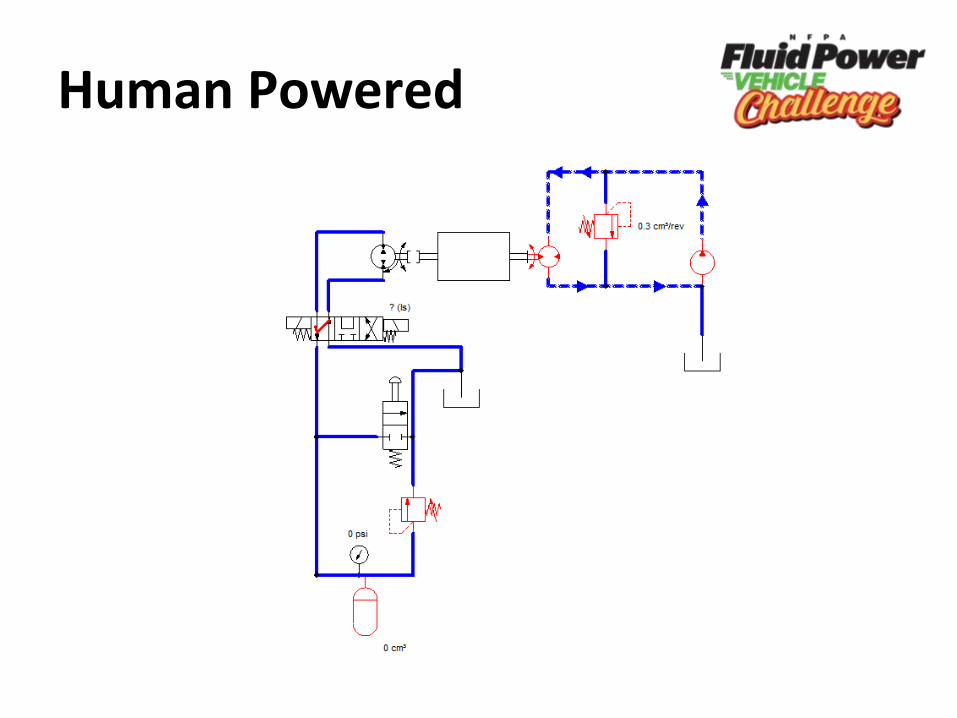
Human Powered
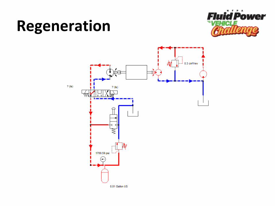
Regeneration
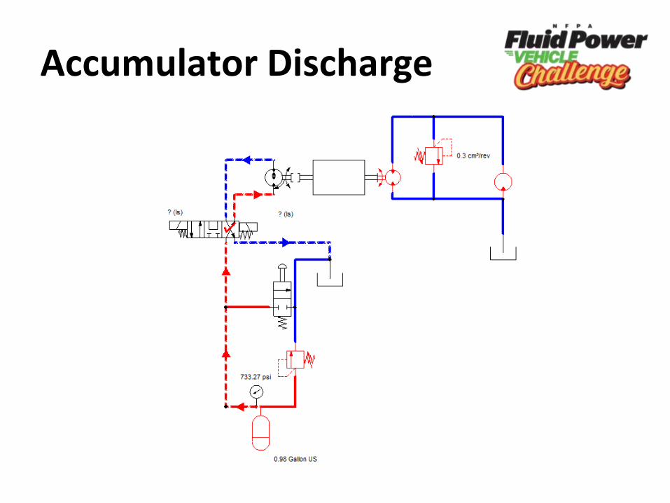
Accumulator Discharge
Power Input
Chain and Sprocket
• Much more efficient
• Easy to use
• Allows for a variety of gear ratios
• Easier to obtain parts
• Cheaper to buy components
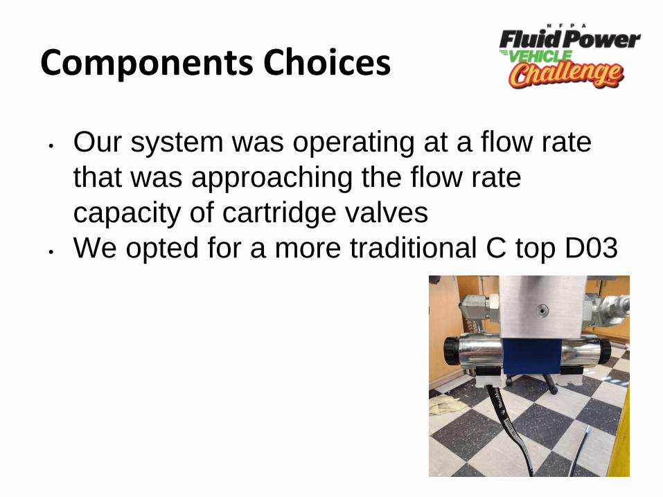
Components Choices
• Our system was operating at a flow rate
that was approaching the flow rate
capacity of cartridge valves
• We opted for a more traditional C top D03
Motor/Pump Choice
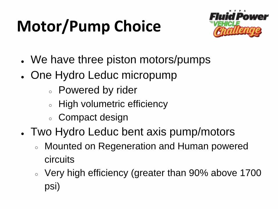
● We have three piston motors/pumps
● One Hydro Leduc micropump
○ Powered by rider
○ High volumetric efficiency
○ Compact design
● Two Hydro Leduc bent axis pump/motors
○ Mounted on Regeneration and Human powered
circuits
○ Very high efficiency (greater than 90% above 1700
psi)
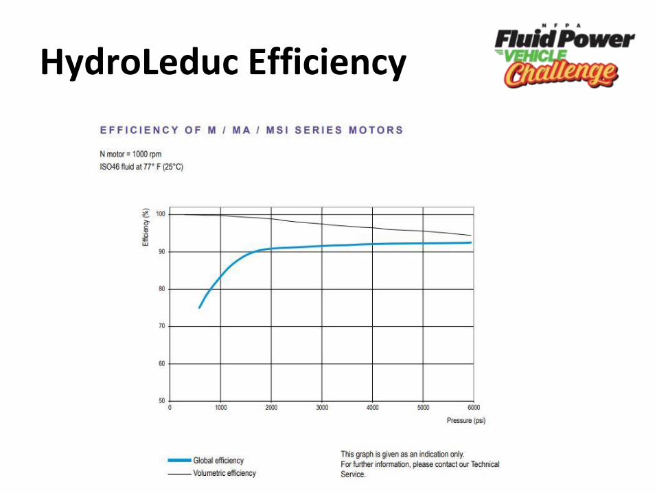
HydroLeduc Efficiency
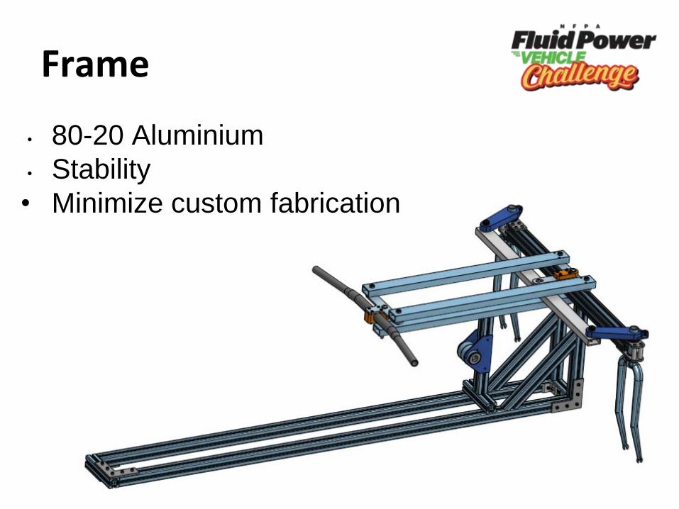
Frame
• 80-20 Aluminium
• Stability
• Minimize custom fabrication
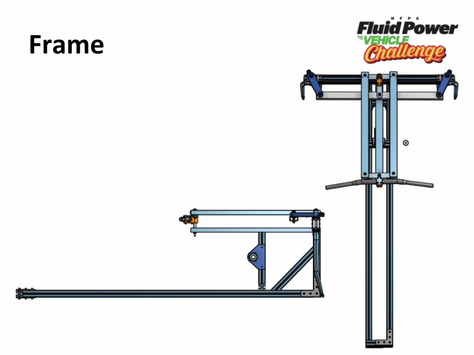
Frame
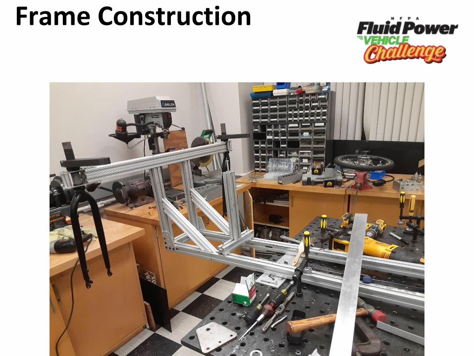
Frame Construction
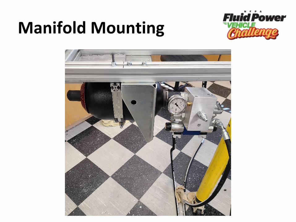
Manifold Mounting
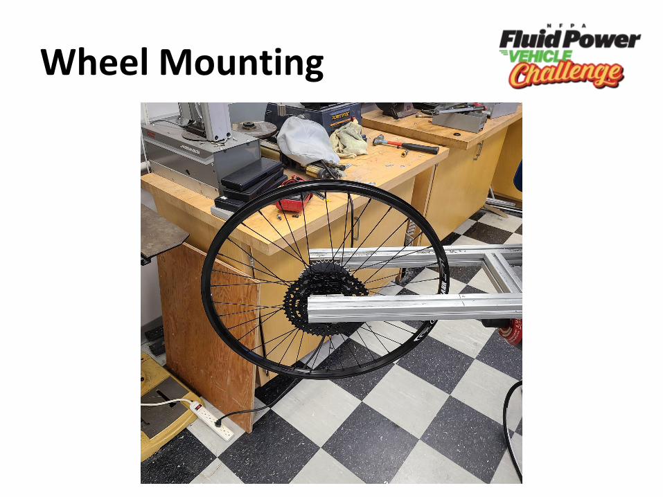
Wheel Mounting
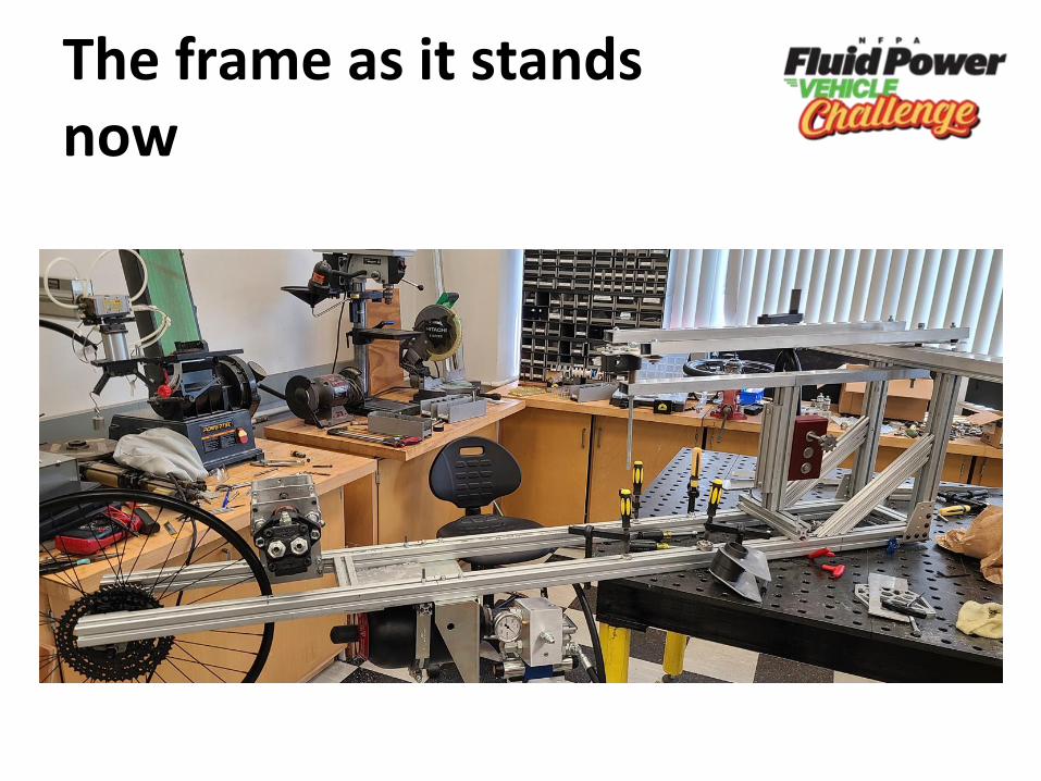
The frame as it stands now
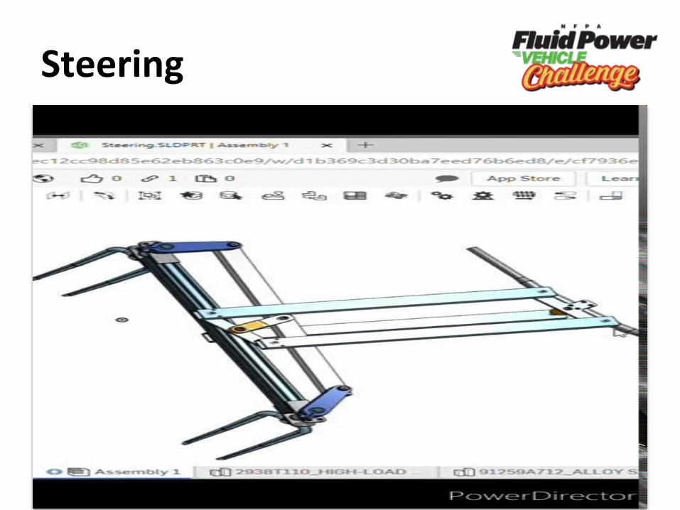
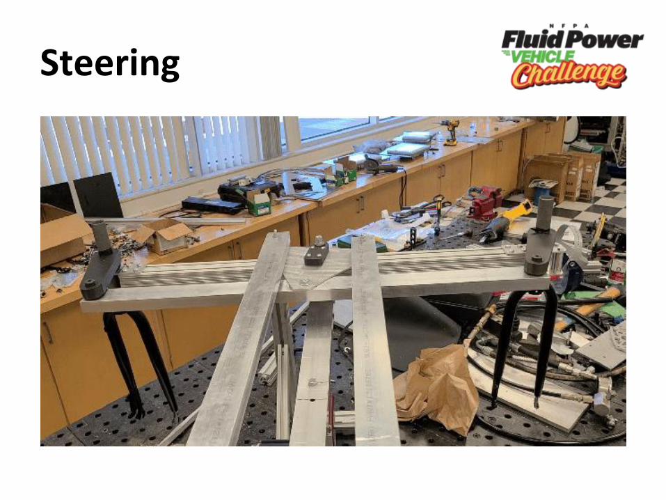
Steering
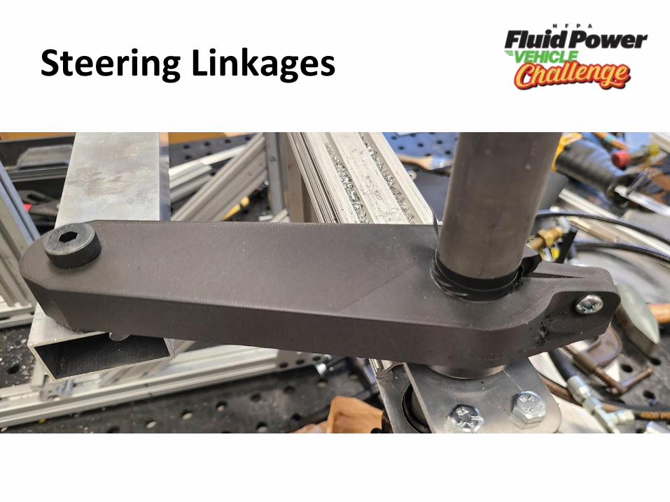
Steering Linkages
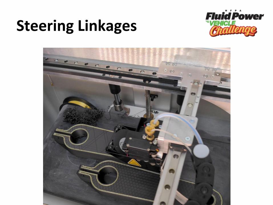
Steering Linkages
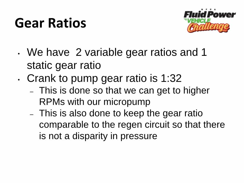
Gear Ratios
• We have 2 variable gear ratios and 1
static gear ratio
• Crank to pump gear ratio is 1:32– This is done so that we can get to higher
RPMs with our micropump
– This is also done to keep the gear ratio
comparable to the regen circuit so that there
is not a disparity in pressure
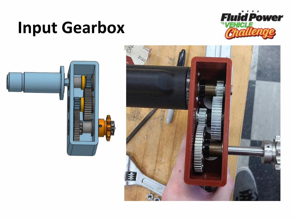
Input Gearbox
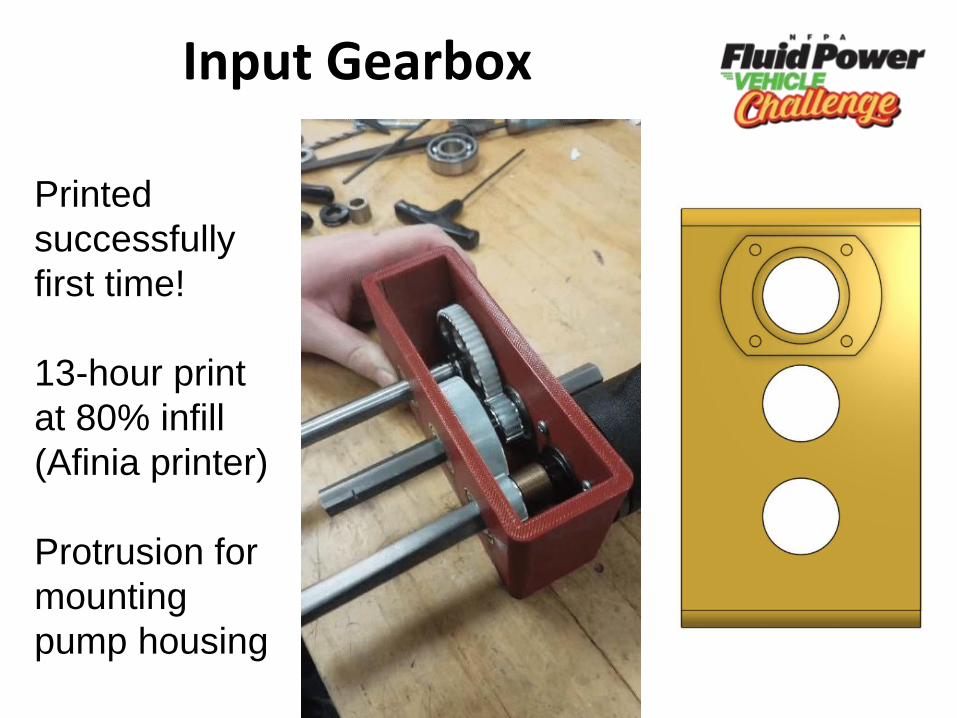
Input Gearbox
Printed
successfully
first time!
13-hour print
at 80% infill
(Afinia printer)
Protrusion for
mounting
pump housing
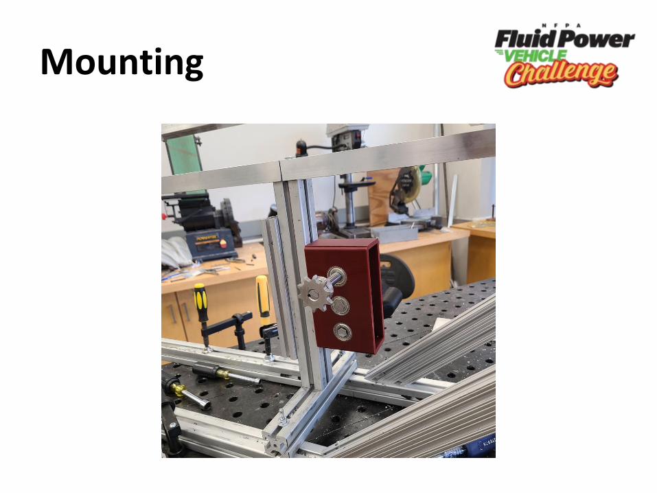
Mounting
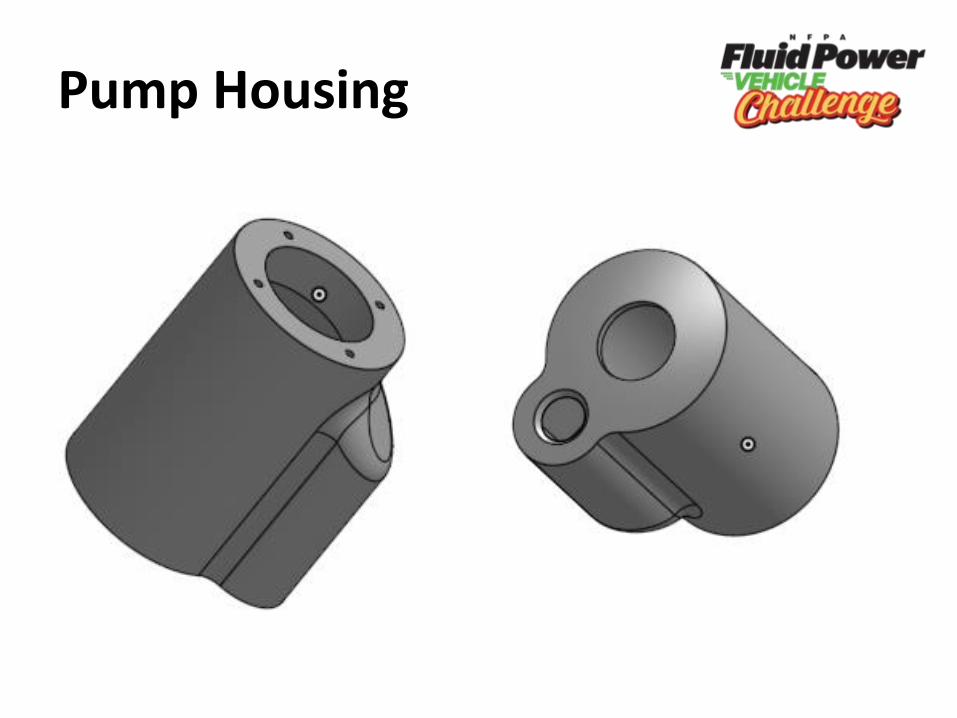
Pump Housing
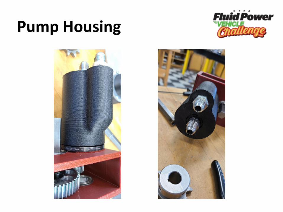
Pump Housing
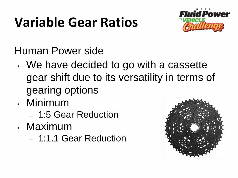
Variable Gear Ratios
Human Power side
• We have decided to go with a cassette
gear shift due to its versatility in terms of
gearing options
• Minimum– 1:5 Gear Reduction
• Maximum– 1:1.1 Gear Reduction

Cassette Disk
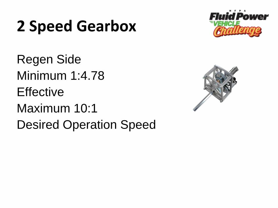
2 Speed Gearbox
Regen Side
Minimum 1:4.78
Effective
Maximum 10:1
Desired Operation Speed
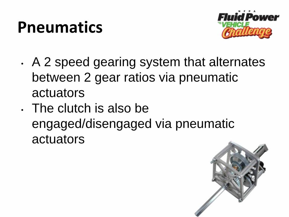
Pneumatics
• A 2 speed gearing system that alternates
between 2 gear ratios via pneumatic
actuators
• The clutch is also be
engaged/disengaged via pneumatic
actuators
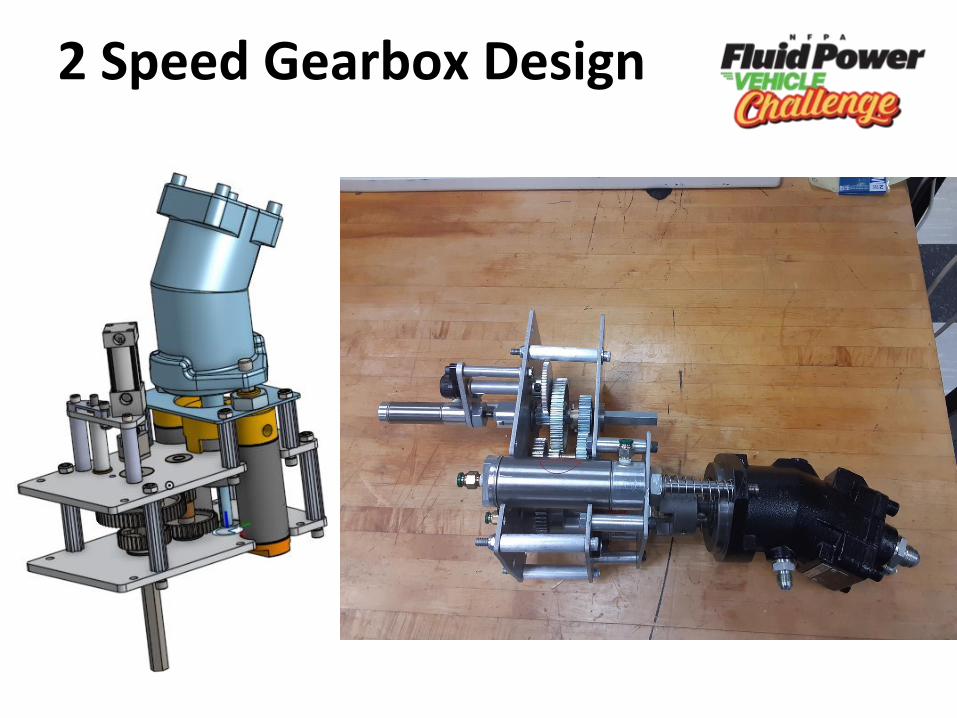
2 Speed Gearbox Design
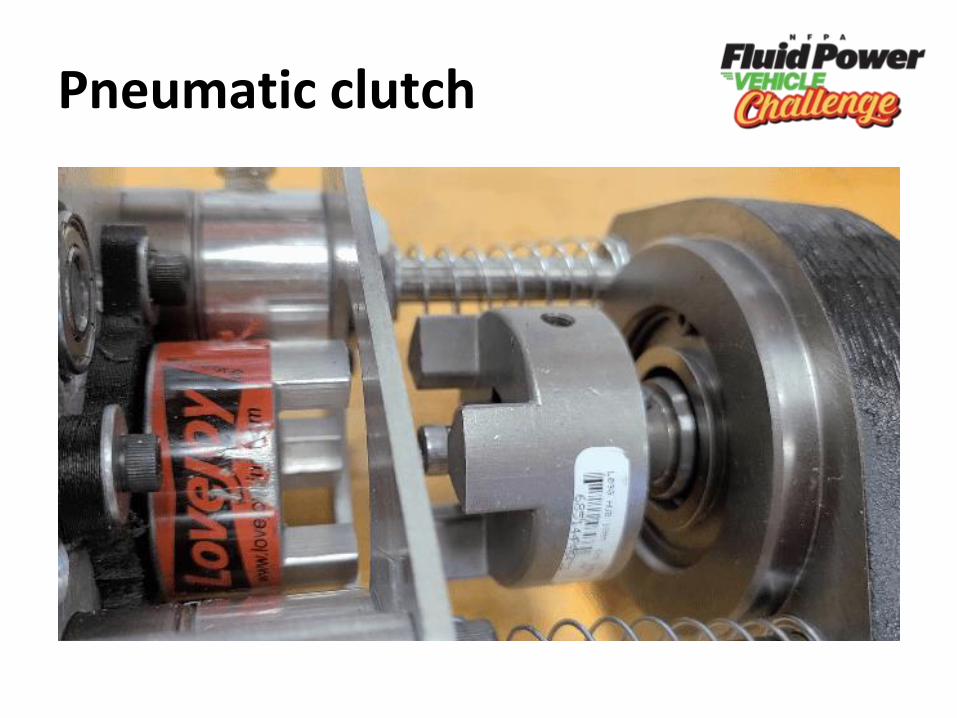
Pneumatic clutch
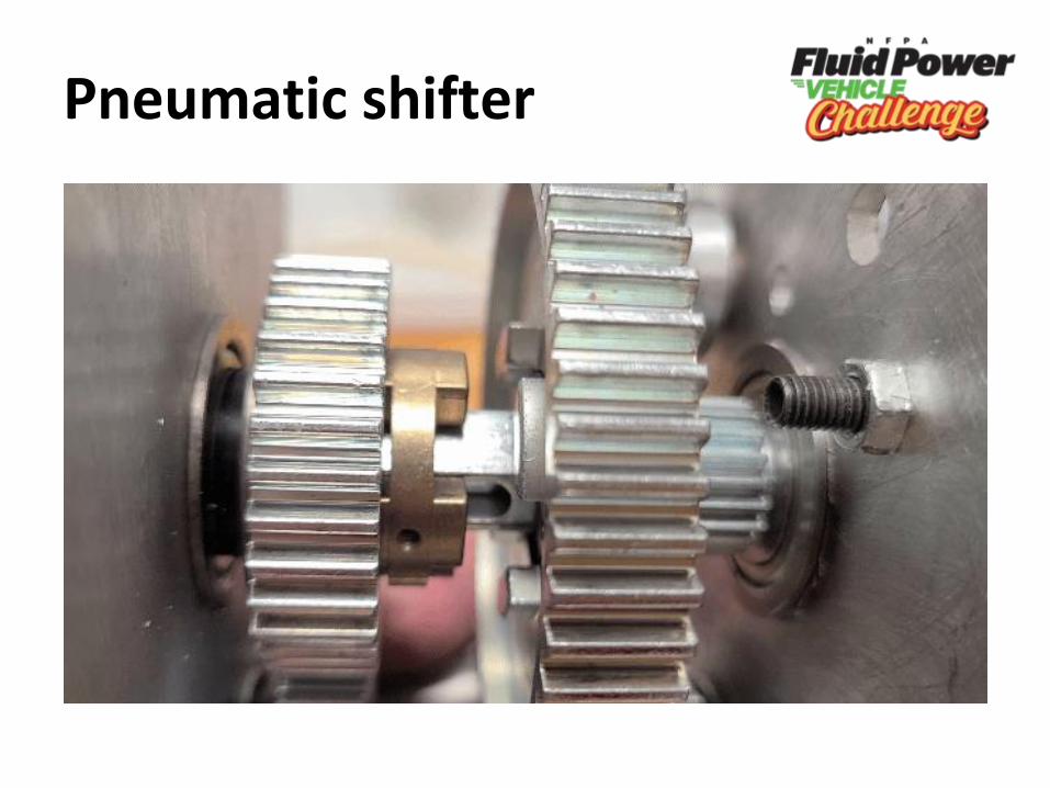
Pneumatic shifter
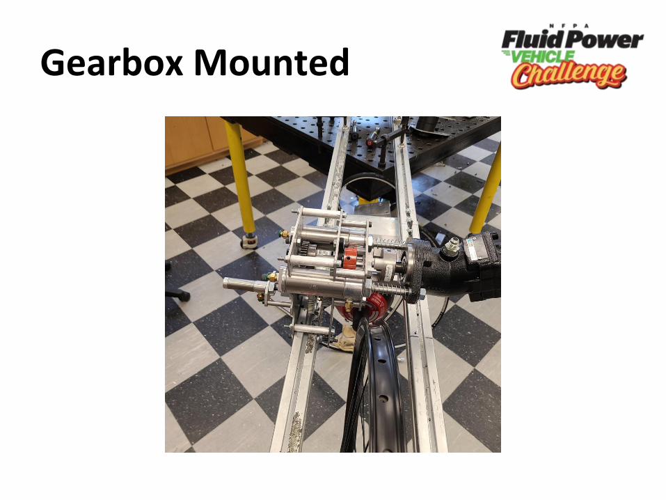
Gearbox Mounted
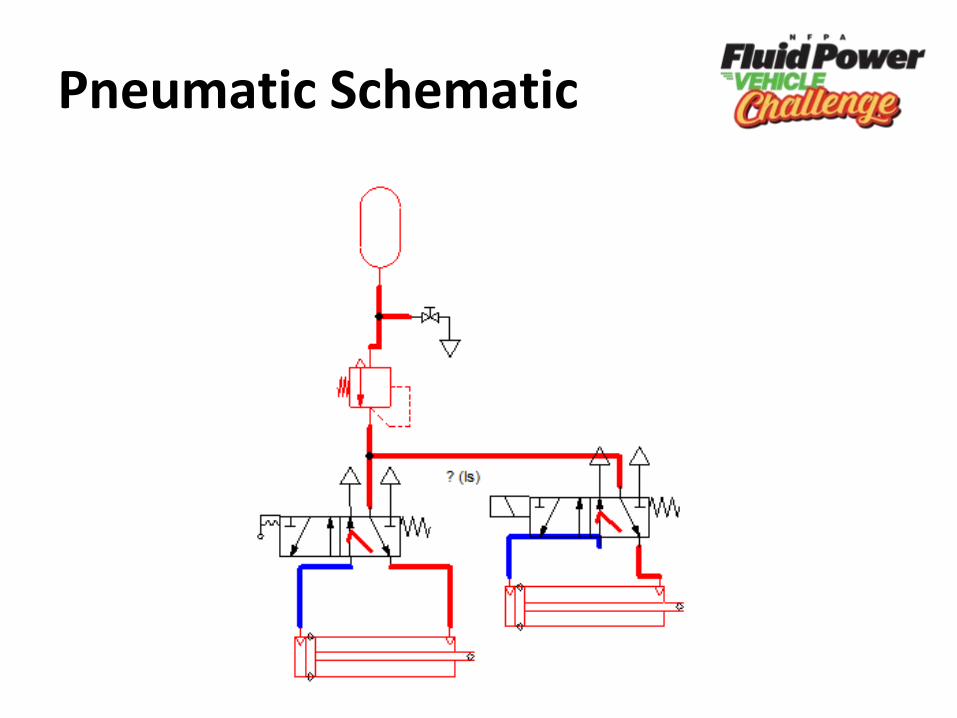
Pneumatic Schematic
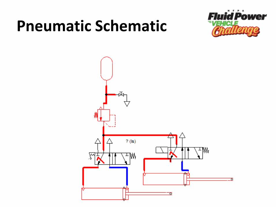
Pneumatic Schematic
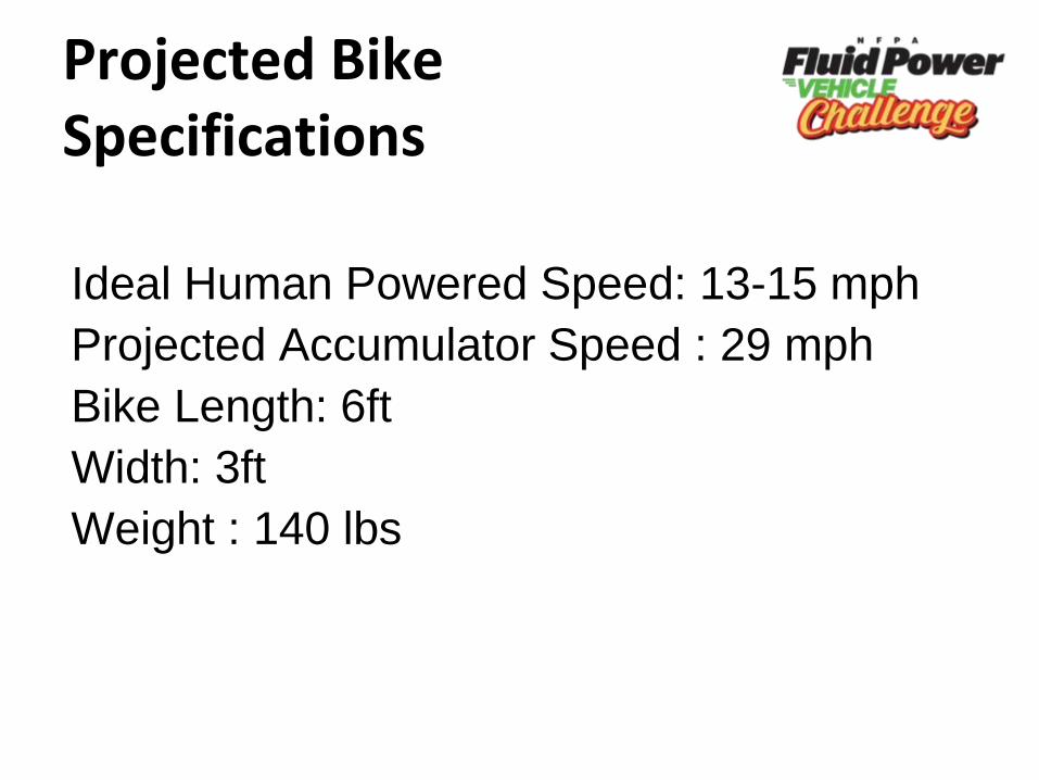
Projected Bike Specifications
Ideal Human Powered Speed: 13-15 mph
Projected Accumulator Speed : 29 mph
Bike Length: 6ft
Width: 3ft
Weight : 140 lbs
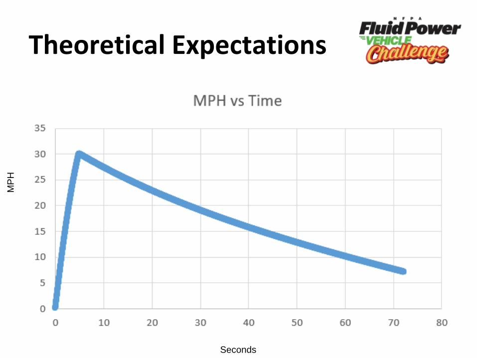
Theoretical Expectations
Seconds
MP
H
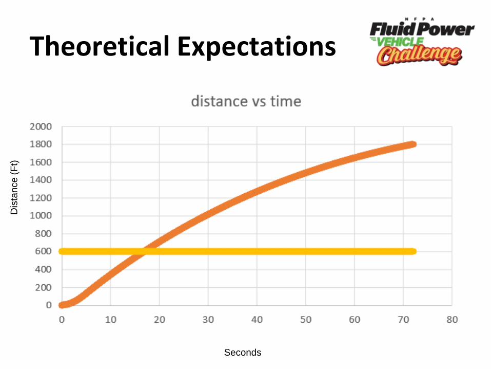
Theoretical Expectations
Seconds
Dis
tan
ce
(F
t)
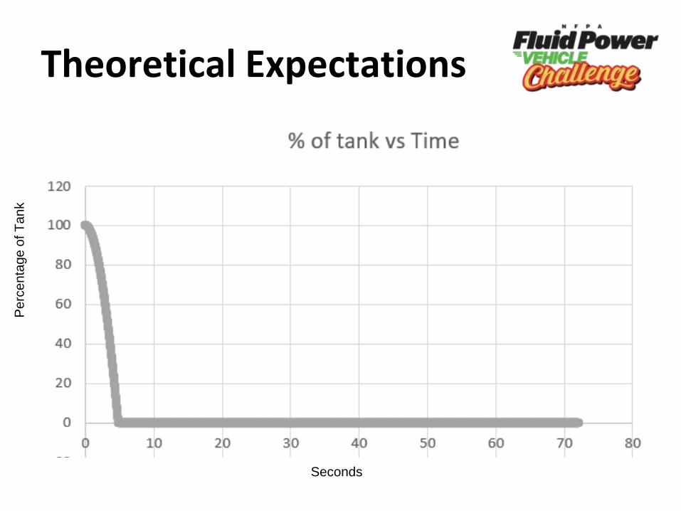
Theoretical Expectations
Seconds
Pe
rce
nta
ge
of T
an
k
PLC Operations
• Operate the pneumatic clutch
• Operate the 2 speed gearbox
• Operate the directional control valve
Program Setup
• Button 1: Activate sol A, clutch, gear
shifter
• Button 2: Activate Sol B
• Button 3: Reset/ E stop
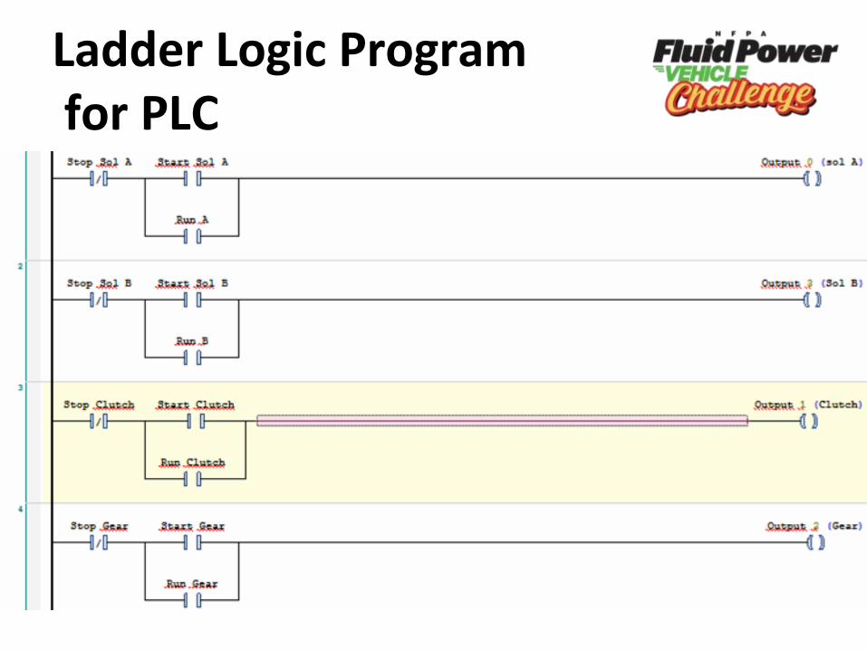
Ladder Logic Programfor PLC
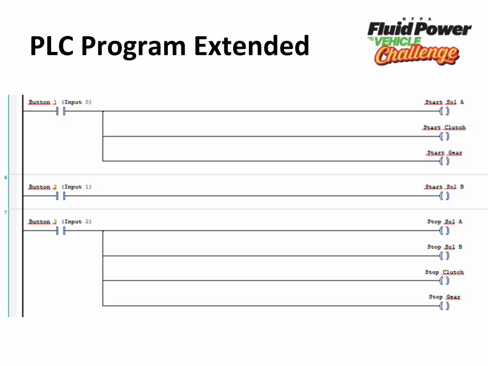
PLC Program Extended
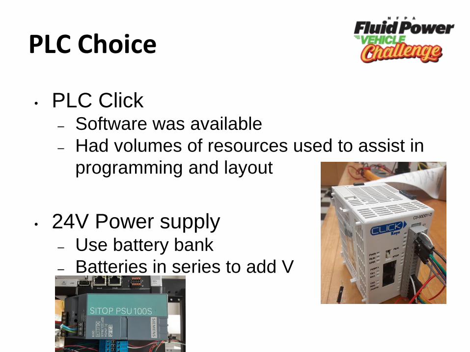
PLC Choice
• PLC Click – Software was available
– Had volumes of resources used to assist in
programming and layout
• 24V Power supply– Use battery bank
– Batteries in series to add V
Challenges
• Volunteers
– Too few members
– Not a lot of experienced members
– Poor Communication
• Mechanical Components
– Parts ordered too late
– Focused too little on assembly
– Not experienced with bicycle components
• Equipment Failure
• Pandemic/Covid-19 (shipping)
Learning as we go
● Efficient time management
○ Working when parts aren’t physically
available
● Maintaining healthy work schedule
● Supporting other team members
● Plan for different experience levels
● Teaching members while maintaining
work efficiency
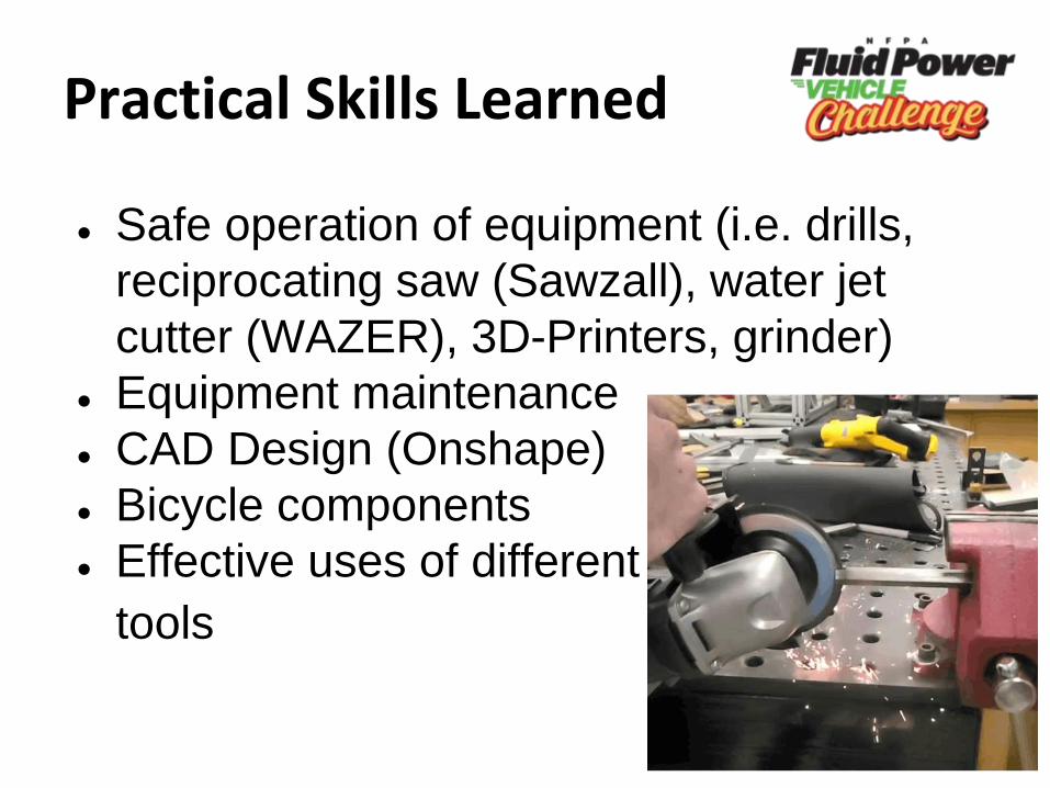
Practical Skills Learned
● Safe operation of equipment (i.e. drills,
reciprocating saw (Sawzall), water jet
cutter (WAZER), 3D-Printers, grinder)
● Equipment maintenance
● CAD Design (Onshape)
● Bicycle components
● Effective uses of different
tools
Social/Teamwork Skills Learned
● Prioritization and delegation of tasks
● Learning to effectively teach each other
● Seeking collaboration
● Concise and effective communication
Machines/Software Used
• WAZER Water Jet Cutter
• Automation Studio
• Onshape
• Afinia 3D Printer
• Markforged 3D Printer
• Basic metal working
• General hand tools
• Excel
Water Jet Cutter (WAZER)
• Setup– Proper set up procedures
– Proper setup of the .dxf files
– Correctly securing material to cut bed
• Running– Looking for cut errors / General supervision
• Maintenance– Diagnosing issues
– Fixing issues
– Preventing further issues
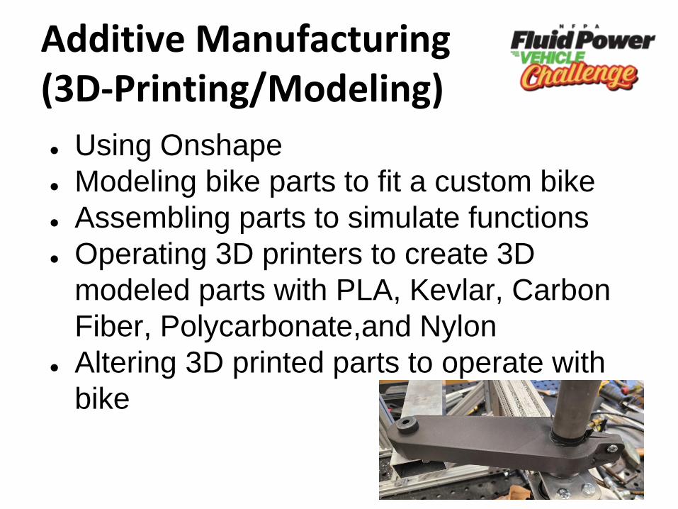
Additive Manufacturing (3D-Printing/Modeling)
● Using Onshape
● Modeling bike parts to fit a custom bike
● Assembling parts to simulate functions
● Operating 3D printers to create 3D
modeled parts with PLA, Kevlar, Carbon
Fiber, Polycarbonate,and Nylon
● Altering 3D printed parts to operate with
bike
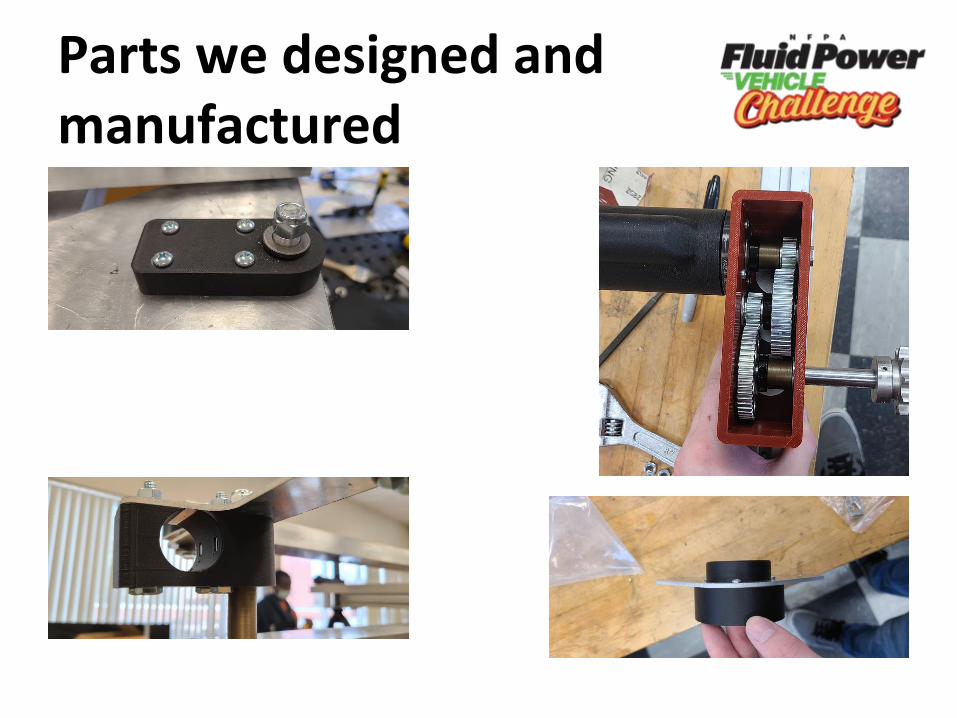
Parts we designed and manufactured
Communication / Team Management
• Weekly Meetings– Task delegation
– Group problem solving
– Checkups
• Individual Meetings– Work 1:1 with team advisor
– Prevented further collaboration
• Communication– Email
– Text
What could be done differently
● Create CAD of the entire bike first
● Deadline for delegated tasks
● Avoid over reliance on machines
(WAZAR)
● Minimize custom fabrication (almost
impossible)
● Better Organization and structure
● More recruitment
What we will continue working on
• Electronics– Flesh out and wire PLC
• Mounting– Mount Motors
– Fully mount manifold/hydraulics
– Set up power input
• Steering– Add Handlebar
– Attach wheels to steering hook
– Finish manufacturing plates
• Make it race worthy!

Thank you for your time!