final report - lehigh university · all specimens were fabricated at full-scale and tested in a...
TRANSCRIPT

ATLSS is a National Center for Engineering Research on Advanced Technology for Large Structural Systems
117 ATLSS Drive
Bethlehem, PA 18015-4729
Phone: (610)758-3525 www.atlss.lehigh.edu Fax: (610)758-5902 Email: [email protected]
T.C.S. TWISTER CONNECTOR UNIVERSAL FORM CLAMP COMPANY
IN-PLANE PERFORMANCE
FINAL REPORT
By Clay Naito, Principal Investigator
Wesley Peter, Graduate Research Assistant Joe Creek, Graduate Research Assistant
March 2006
ATLSS REPORT NO. 06-08

ATLSS #06-08 Universal Form Clamp Co. TCS Twister Connector Page 1 of 14 Final Report
ABSTRACT
This report summarizes the in-plane performance of the Twister Connector Type T.C.S. developed by Universal Form Clamp Company. They are intended for use as flange-to-flange connectors between precast double tee panels with 2-in. flanges. The connector was tested under monotonically increasing shear, monotonically increasing tension, cyclic shear, and monotonically increasing shear with tension opening of half the shear deformation. The resulting capacities and associated damage are summarized in the report. This work was funded by Universal Form Clamp Co. and was conducted at the ATLSS Center at Lehigh University.

ATLSS #06-08 Universal Form Clamp Co. TCS Twister Connector Page 2 of 14 Final Report
BACKGROUND
As a means of assessing the displacement capacity and structural stiffness of connections in precast diaphragms, an experimental study was conducted. A subassembly consisting of the connector and a portion of the surrounding diaphragm was developed. The subassemblies include two connectors embedded in a standard 2-in. precast section. All specimens were fabricated at full-scale and tested in a combinations of horizontal shear and/or tension. This report summarizes the experimental results of the Twister connector type T.C.S. tested under displacement control in monotonic tension, monotonic shear, cyclic shear and combined shear with tension.
SUBASSEMBLY DETAILS
The subassembly was developed assuming that the connectors are spaced at 4 feet and embedded in a double tee panel with a 2ft distance from the DT web to the free flange face. The test specimens are fabricated from two panels 2ft wide and 4ft long (Figure 1). The panels are connected to form a 4ft square subassembly. Welded wire reinforcement (WWR) is included in each panel to meet ACI temperature and shrinkage reinforcement requirements. In addition to the WWR conventional reinforcement is used to maintain integrity during testing. The bars are placed at the periphery of the panel to minimize influence on the connector response. The supplemental reinforcement is illustrated in Figure 3.
The Twister Connector Type T.C.S. developed by Universal Form Clamp Company was evaluated. The connector (Figure 2) is designed for placement in 2-in. DT flanges. The connector is fabricated from fabricated from A304 stainless steel and connected to the adjacent panel using an A304 stainless steel slug and 308-16 welding electrode. The welds were conducted at room temperature using a SMAW process according to AWS specifications.
4'
6"
6"
4'-014"
TOP PLAN
6X6 W2.9XW2.9
4"
SIDE ELEVATION
4x1x3/8RectangularS.S.304 Slug
TwisterConnector BStainless Stl. 304
8"
2"1/4 4
SMAW308-16 Electrode
TwisterConnector
Figure 1: Specimen details

ATLSS #06-08 Universal Form Clamp Co. TCS Twister Connector Page 3 of 14 Final Report
6.7500
7.5000
120°120°
1.0000
7.000-TCS
19.5547
73°
.1876
55°-70°
R.250
R.5000
180°
R.500
7.5000
6.7500
60°
60°
3.5000
Ø.2500
T C S
FORGE INWARD TYP.
.5000
Ø.3500
1.2500
1.1250
3.2500
.5000Ø.3500
1.1250
TOP VIEW
SIDE VIEW
BOTTOM VIEW
.3215
.3215
DETAIL "A"
UP
FORGE INWARD LOGO TYP.
1.00
R.3143
Figure 2: Twister Connector B
Plan View
#4 SupplementalReinforcement
234"
1'
4'
8"
8"
1'
4'-014"
8" 118" diameter
anchor holes
Figure 3: Supplemental reinforcement layout and construction details
DEFORMATION PROTOCOLS The connectors were evaluated under in-plane shear, tension, and combined shear with tension. All tests were conducted under quasi-static displacement control at a rate less than 0.05in/sec. The tests were continued until failure. Failure is defined as the point where the specimen capacity drops below 25% of the measured ultimate. Five displacement protocols have been developed to represent the spectrum of demands a local diaphragm connector could experience under lateral loading [Naito 2005]. Three of these deformation protocols were used in the current study:
1. Monotonic Shear 2. Cyclic Shear 3. Monotonic Tension

ATLSS #06-08 Universal Form Clamp Co. TCS Twister Connector Page 4 of 14 Final Report
Monotonic Shear
The monotonic shear tests were conducted to evaluate the connector response under pure shear deformation. The original panel separation of was maintained through the test. The test represents the joint condition where the panels are shearing without any flexural opening or closing. The test thus provides an estimate of average connector yield, peak strength, and the deformation capacity. Monotonic shear protocol consists of three cycles to 0.01-in. to estimate initial stiffness and verify equipment operation. Afterwards, the specimens were loaded monotonically to failure (Figure 4).
Cyclic Shear
Cyclic shear tests provide insight on the degradation of shear properties (i.e., stiffness and ultimate strength) under loading reversals. The loading protocol is based on the PRESSS program [Priestley 1992]. Three preliminary cycles to 0.01-in. are conducted to evaluate control and acquisition accuracy. The remaining protocol consisted of groups of three symmetric shear cycles at increasing deformation levels. Each level is based on a percentage of a reference deformation computed from the preceding monotonic test. The reference deformation represents the effective yield deformation of the connector. It is computed by taking the intercept of a horizontal line at the max load and a secant stiffness line at 75% of the max load (Figure 4 inset). Three elastic levels of 0.25D, 0.50D and 0.75D followed by inelastic cycles to 1.0D, 1.5D, 2.0D, 3.0D, 4.0D, 6.0D, 8.0D, etc… were conducted. The loading protocol is illustrated in Figure 4.
Monotonic Tension
In current diaphragm design, the flexural diaphragm tensile forces are assumed to be resisted by the chord reinforcement. The contribution of shear connectors to flexural resistance is commonly neglected. Previous research has shown that in many cases web connectors provide high tension stiffness. To quantify the relative tensile contribution of the web connectors and chord connectors, a monotonic tension tests were conducted. The loading protocol consisted of three tension/compression deformations to 0.01-in. followed by a monotonically increasing tension deformation to failure (Figure 5). The test was paused at each 0.1-in. for observations. The test was conducted with no shear force. This was achieved by disconnecting the shear actuator prior to testing.
Note, ∆=Reference Deformation From Monotonic Test
1.0∆
0
Shear Displacement
0 10 20 30 Cycle #
Monotonically Increasing Displacement
Incr
ease
in in
crem
ents
of
2.0∆
unt
il fa
ilure
Applied Shear
Displacement
[email protected]∆ [email protected]∆ [email protected]∆ [email protected]∆[email protected]∆
2.0∆
3.0∆
4.0∆
5.0∆
6.0∆
7.0∆
8.0∆
Tension Displacement Compensation to provide constant panel spacing
Vmax0.75Vmax
∆
Monotonic response
Force
Displacement
Figure 4: Shear loading protocol

ATLSS #06-08 Universal Form Clamp Co. TCS Twister Connector Page 5 of 14 Final Report
Tmax0.75Tmax
∆
Monotonic response
Force
Displacement
Applied Tension/Compression
Displacement
Note, ∆=Reference Deformation
1.0∆
0
Tension Displacement
10 20 30 Cycle #
Monotonically Increasing Displacement
Incr
ease
in in
crem
ents
of
2.0∆
unt
il fa
ilure
Shear Displacement Compensation to
provide zero shear
[email protected]∆[email protected]∆ [email protected]∆ [email protected]∆
[email protected]∆[email protected]∆
2.0∆
3.0∆
4.0∆
5.0∆
6.0∆
7.0∆
8.0∆
Applied Tension/Compression Displacement
Compression Force
Deform in Compression until Force Equals Preceding Cycle Tension Force
Figure 5: Tension/Compression protocol
MATERIAL PROPERTIES The base 4-in. and 2-in. precast panels were fabricated using ready mix concrete with design 28-day strength of 6000 psi. The measured compressive strengths from 4x8 cylinder tests indicate that the concrete panels were between 5 ksi and 6 ksi during when tested. The WWR used in the base panel met the requirements of ASTM A185 grade 65 steel. The connectors were furnished by Universal Form Clamp. Material data supplied with the connectors indicated that the connector was fabricated from A-304 stainless steel, mill certifications were not available. The slugs were fabricated from A304 stainless steel. The measured concrete strengths and mill certified steel properties are presented in Table 1.
Table 1: Material Properties Capacity
Age of Concrete Compressive Strength, f’c (psi) 7-day 4880 ±280 28-day 5490 ± 430
Size Reinforcement Usage Grade Yield Stress (ksi) Ultimate Strength (ksi) 4x1x3/8 Connector Slug A304 40.0 84.3
#4 Reinforcing Bars A706 68.0* 90.0* W2.9XW2.9 6X6 Precast Panel Mesh A185 Gr.65 65.00* 108.5*
* Data unavailable, value assumed

ATLSS #06-08 Universal Form Clamp Co. TCS Twister Connector Page 6 of 14 Final Report
TEST B1: TCS TWISTER CONNECTOR UNDER MONOTONIC TENSION The performance of TCS Twister Connector subjected to monotonic tension is presented in this section. As discussed in the loading protocol, tensile displacement was applied with shear force unrestrained, Fv=0. Panel failure consisted of cracking near the connector faceplates on the underside of the panel. This was followed by significant bending of the connector faceplate and pullout of the connector tension legs in the fixed panel. Noticeable slips were observed at 1.56-in and 3.14-in. Spalling of the cover concrete below the connector occurred as pullout progressed. As shown in Figure 3 the WWR was placed above the connector legs. Placing the WWR below the connector would have likely moved the damage to the top surface. The observed key events and the corresponding displacement level are presented in Table 2. The photos of the damage are presented in Figure 6 and Figure 7. The global force deformation response and backbone curve are presented in Table 3 and Figure 8.
Figure 6: Damage state at 0 and 3.0 inch tensile opening
a) b)
c) Figure 7: Damage state at tension deformation of a) 1.0-in., b) 1.6-in. (from underside) and c) end of test

ATLSS #06-08 Universal Form Clamp Co. TCS Twister Connector Page 7 of 14 Final Report
Table 2: Key Test Observations TCS (Monotonic Tension)
Event # Tensile ∆ [in.] Event Description
1 0.02 Minor bending of free panel face plate. 2 0.06 Minor bending of fixed panel face plate. 3 0.1 Additional bending of fixed panel face plate. 4 0.2 Concrete cracking on both panels at connector legs bend. 5 0.3 Concrete cracking audible. Spalling underneath fixed panel 6 0.4 Both panel face plates display significant bending. 7 0.5 Concrete spalling audible. 8 0.6 Connector slightly rotated. 9 0.8 Spalling at free panel connection corner.
10 0.9 Connector rotation stopped. 11 1.3 Concrete cracking audible. 12 1.4 Concrete cracking audible.
13 1.6 Spalling under fixed panel observed. Audible pullout of connector leg from fixed
panel. Minor weld fracture observed. 14 1.9 Concrete spalling visible under fixed panel. 15 3.5 End of Test
Table 3: Experimental Results Backbone Curve TCS (Monotonic Tension)
Step Tensile Displacement Tensile Force Minor faceplate bending 0.059 2.55 Concrete cracking at legs 0.152 3.74 Spalling under panel 0.220 2.42 Max load 1.486 7.55 Tension pullout of one leg 1.557 1.84 - 2.084 3.32 - 2.281 2.18 Tension pullout of other leg 3.139 5.23 End of test 3.524 1.02
0
1
2
3
4
5
6
7
8
0 1 2 3 4Axial Displacement [in]
Forc
e [k
ips]
Figure 8: Force and axial displacement (Monotonic Tension)

ATLSS #06-08 Universal Form Clamp Co. TCS Twister Connector Page 8 of 14 Final Report
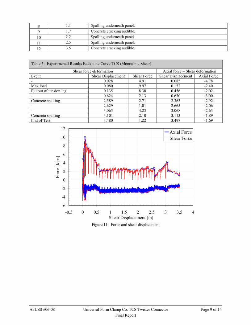
TEST B2: TCS TWISTER CONNECTOR UNDER MONOTONIC SHEAR The performance of TCS Twister Connector subjected to monotonic shear is presented in this section. As discussed in the loading protocol, shear displacement was applied with tensile displacement restrained, ∆T=0. Connector damage was characterized by cracking near the connector compression legs at the face of the panel. This was followed by pullout of the connector tension legs at a shear deformation of 0.14-in. Following pullout a low level of shear resistance (approximately 2 kips) was provided through bearing of the connector on the concrete. At approximately 3-in of shear wedging of concrete occurred at the joint resulting in a small increase in resistance. The observed key events and the corresponding displacement level are presented in Table 4. The photos of the damage are presented in Figure 9 and Figure 10. The global force deformation response and backbone curve are presented in Table 5 and Figure 11.
Figure 9: Damage state at 0 and 3.0 inch shear opening
a) b)
c) d) Figure 10: Damage state at shear deformation of a) 0.2, b) 0.7, c) 2.6, and d) 3.5-in.
Table 4: Key Test Observations TCS (Monotonic Shear)
Event # Shear ∆ [in.] Event Description
1 0.1 Cracking at connector in free panel. 2 0.2 Cracking at compression legs. Concrete cracking audible. 3 0.3 Extension of compression leg cracks. 4 0.4 Spalling underneath the panel. Bending of compression leg in free panel. 5 0.5 Concrete cracking audible. 6 0.7 Spalling at connector compression legs. 7 1 Spalling at connector compression legs.
ATLSS #06-08 Universal Form Clamp Co. TCS Twister Connector Page 9 of 14 Final Report
8 1.1 Spalling underneath panel. 9 1.7 Concrete cracking audible.
10 2.2 Spalling underneath panel. 11 2.5 Spalling underneath panel. 12 3.5 Concrete cracking audible.
Table 5: Experimental Results Backbone Curve TCS (Monotonic Shear)
Shear force-deformation Axial force – Shear deformation Event Shear Displacement Shear Force Shear Displacement Axial Force - 0.028 4.91 0.085 -4.78 Max load 0.080 9.97 0.152 -2.40 Pullout of tension leg 0.135 8.30 0.456 -2.02 - 0.624 2.13 0.630 -3.00 Concrete spalling 2.589 2.71 2.363 -2.92 - 2.629 1.01 2.665 -2.06 - 3.065 4.23 3.068 -2.63 Concrete spalling 3.101 2.10 3.113 -1.89 End of Test 3.480 1.22 3.497 -1.69
-6
-4
-2
0
2
4
6
8
10
12
-0.5 0 0.5 1 1.5 2 2.5 3 3.5 4Shear Displacement [in]
Forc
e [k
ips]
Axial ForceShear Force
Figure 11: Force and shear displacement
ATLSS #06-08 Universal Form Clamp Co. TCS Twister Connector Page 10 of 14 Final Report
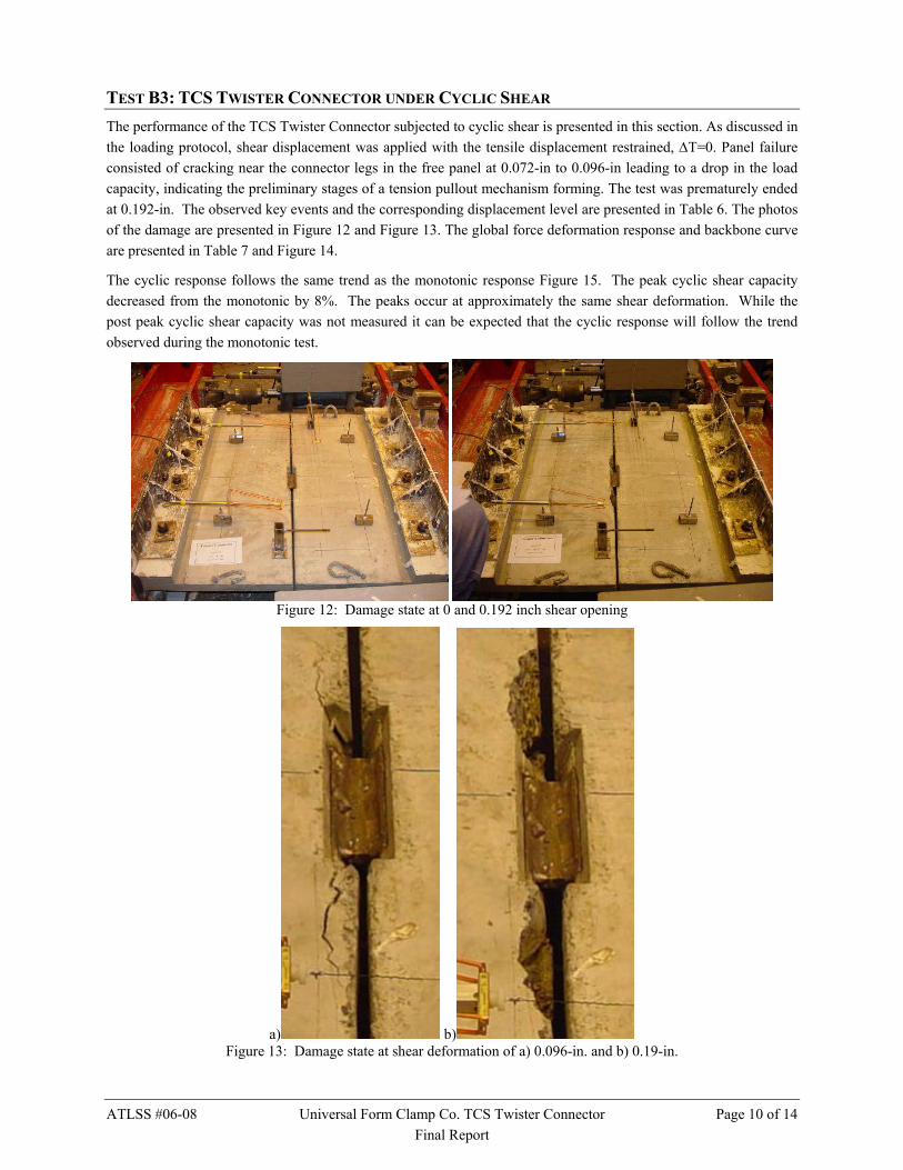
TEST B3: TCS TWISTER CONNECTOR UNDER CYCLIC SHEAR The performance of the TCS Twister Connector subjected to cyclic shear is presented in this section. As discussed in the loading protocol, shear displacement was applied with the tensile displacement restrained, ∆T=0. Panel failure consisted of cracking near the connector legs in the free panel at 0.072-in to 0.096-in leading to a drop in the load capacity, indicating the preliminary stages of a tension pullout mechanism forming. The test was prematurely ended at 0.192-in. The observed key events and the corresponding displacement level are presented in Table 6. The photos of the damage are presented in Figure 12 and Figure 13. The global force deformation response and backbone curve are presented in Table 7 and Figure 14.
The cyclic response follows the same trend as the monotonic response Figure 15. The peak cyclic shear capacity decreased from the monotonic by 8%. The peaks occur at approximately the same shear deformation. While the post peak cyclic shear capacity was not measured it can be expected that the cyclic response will follow the trend observed during the monotonic test.
Figure 12: Damage state at 0 and 0.192 inch shear opening
a) b) Figure 13: Damage state at shear deformation of a) 0.096-in. and b) 0.19-in.

ATLSS #06-08 Universal Form Clamp Co. TCS Twister Connector Page 11 of 14 Final Report
Table 6: Key Test Observations TCS (Cyclic Shear)
Event # Shear ∆ [in.] Event Description 1 0.01 Concrete cracking audible. 2 -0.024 Concrete cracking audible. 3 0 Concrete cracking audible. 4 0.048 Concrete cracking audible. 5 0.072 Increase in load capacity. 6 -0.072 Concrete cracking at connector on free panel. 7 0.096 Additional cracking near connector on free panel. Decrease in load. 8 -0.096 Decrease in load. 9 0.192 Spalling near connector on free panel, bending of compression leg of connector.
10 -0.192 HSM pressure shutoff, end of test.
Table 7: Experimental Results Backbone Curve TCS (Cyclic Shear)
Event Shear Displacement [in.] Shear Force [kip] End of test -0.193 -7.38 - -0.141 -7.69 Cracking at legs in free panel -0.094 -7.41 Max reverse load -0.070 -8.25 - -0.033 -7.52 - -0.011 -5.75 - 0 0 - 0.009 4.98 - 0.021 6.87 0.047 7.48 Max load 0.071 9.85 Cracking at legs in free panel 0.143 9.32 Spalling at free panel comp. leg 0.185 8.43
-10-8-6-4-202468
1012
-0.3 -0.2 -0.1 0 0.1 0.2 0.3Shear Displacement [in]
Forc
e [k
ips]
Figure 14: Force and shear displacement

ATLSS #06-08 Universal Form Clamp Co. TCS Twister Connector Page 12 of 14 Final Report
-10-8-6-4-202468
10
-1 -0.5 0 0.5 1Shear Displacement [in]
Forc
e [k
ips]
Shear Force
Cyclic Shear Backbone
Monotonic Shear Backbone
Figure 15: Comparative cyclic and monotonic response
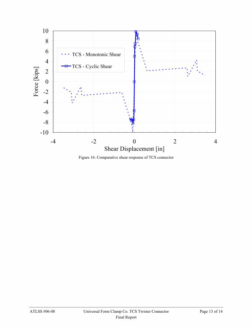
CONCLUSIONS The TCS Twister Connector developed by Universal Form Clamp Company was examined under in-plane loads. The connectors are intended for use as flange-to-flange connectors between precast double tee panels with 2-in. flanges. The connectors were precast in 2-ft. x 4-ft. panels of appropriate thickness. The connectors were tested under monotonically increasing shear, monotonically increasing tension, and cyclic shear.
The resulting capacities of the connector under the applied demands are summarized in Table 8. The shear and tension capacities are on the same order. The monotonic and cyclic shear responses are summarized in Figure 16. The cyclic shear resulted in a decrease in load capacity of approximately 10% in one direction. In the other direction the cyclic and monotonic strength was comparable.
Table 8: Maximum load capacity [kips]
Connector MT MV CV MTV
TCS 7.55 9.97 +9.85 / -8.25 N.A.
N.A. – Not Available
ATLSS #06-08 Universal Form Clamp Co. TCS Twister Connector Page 13 of 14 Final Report
-10-8-6-4-202468
10
-4 -2 0 2 4Shear Displacement [in]
Forc
e [k
ips]
TCS - Monotonic Shear
TCS - Cyclic Shear
Figure 16: Comparative shear response of TCS connector