final water design report - buckeyeaz.gov
TRANSCRIPT

�
FINAL WATER DESIGN REPORT CITY OF BUCKEYE – ROOSEVELT STREET IMPROVEMENT DISTRICT
ENGINEERING SERVICES Contract No. 2014-071
April 2017
Prepared for:
Prepared by:
5727 N. 7th Street, Suite 120 Phoenix, AZ 85014
O: 602.263.1177 | F: 602.277.6286
DISCLAIMER: THE CITY APPROVES THIS REPORT FOR CONCEPT ONLY AND ACCEPTS NO LIABILITY FOR ERRORS OR OMISSIONS
BY: BUCKEYE CITY ENGINEER DATE

Roosevelt Street Improvement District Engineering Services Final Water Report
April 2017 City of Buckeye, AZ
��
TABLE OF CONTENTS
1.0 EXECUTIVE SUMMARY ............................................................................................ 1
2.0 INTRODUCTION ......................................................................................................... 1 2.1 GENERAL BACKGROUND .................................................................................... 1 2.2 PROJECT LOCATION ........................................................................................... 2 2.3 FLOW TEST RESULTS......................................................................................... 3
3.0 WATER IMPROVEMENTS ......................................................................................... 4 3.1 EXISTING WATER IMPROVEMENTS ...................................................................... 4 3.2 ON-SITE WATER IMPROVEMENTS ....................................................................... 4
4.0 WATER SYSTEM DESIGN AND ANALYSIS ............................................................. 5 4.1 DESIGN CRITERIA .............................................................................................. 5 4.2 PRESSURE ZONES ............................................................................................. 5 4.3 WATER DEMAND ................................................................................................ 6 4.4 MODELING RESULTS .......................................................................................... 8
5.0 CONCLUSION ............................................................................................................ 9
6.0 REFERENCES .......................................................................................................... 10
TABLES Table 1: City of Buckeye Pressure Zones ..................................................................................... 6�Table 2: Water Demands .............................................................................................................. 7�
FIGURES Figure 1 – Vicinity Map ................................................................................................................. 3Figure 2 – Water Demand Areas .................................................................................................. 8
APPENDICES
Appendix A Fire Flow Tests & Pump Curves Appendix B Link/Node Map & WaterCAD Results
Roosevelt Street Improvement District Engineering Services Final Water Report
April 2017 City of Buckeye, AZ
��
1.0 EXECUTIVE SUMMARY This Water Report has, been prepared for the City of Buckeye’s Roosevelt Street Improvement District Project (RSID). The purpose of this report is to describe the proposed water distribution system for RSID and demonstrate the parameters used to design the system. The criteria used for this report is based on the City of Buckeye Engineering Design Standards, Section 3-1 (Water).
The project site is partially developed and mostly undisturbed desert rangeland. The existing ground generally slopes from the northwest to the southeast. The development will be served by proposed 12” waterlines that will tie into existing waterlines in 215th Avenue and Verrado Way. The proposed water system will require installation of 12” waterlines under Interstate Highway 10 (I-10).
A water Master Design Report was previously prepared for the general area of this project location. The North Airport Road Water Master Plan was prepared July 2006 by RBF Consulting (Project No. JN 45-102450), and revised in August 2010. The proposed transmission and distribution water system facilities from these reports are based on demands/usage that corresponded to the land use categories assigned to parcels at that time. A review of the current land use and zoning for the parcels affected by and adjacent to this project indicate these categories have changed. As such, overall configurations, demands and design of proposed water system facilities will need to vary from what was contemplated in the Master Design Report. This report details these updated system configurations, demands and designs of the proposed water system.
2.0 INTRODUCTION
2.1 General Background The proposed improvements consist of construction of new roadways, water lines, sewer lines, and storm drain facilities. The project site is located near Verrado Way and I-10 in Buckeye, Arizona. This water analysis describes the water system that will be installed as a part of this project.
The proposed system consists of 12” waterlines along public roadway that tie into existing waterlines at several locations. The connection points to the

�
Roosevelt Street Improvement District Engineering Services Final Water Report
April 2017 City of Buckeye, AZ
��
existing systems are at 215th Avenue and Fillmore Street as well as Roosevelt Street and Verrado Way. The connection point at Verrado Way is to an existing 12” PVC waterline west of the intersection. The connection at 215th Avenue north of Fillmore Street is to an existing 12” D.I.P. waterline.
The City of Buckeye Engineering Design Standards, Section 3-1 requires a minimum line size of 16” for water mains located within arterial streets and 12” for water mains located within collector streets unless approved by the City Engineer (para. 3-1.202.D.3.a). 215th Avenue has been identified as a collector street and is designed as a 12” water main to be extended matching the existing 12” water main. Roosevelt Street has been identified as an arterial street and as such the City standard calls for the use of a 16” water main. A 16” water main modelled for Roosevelt Street as a part of the system design was found to not be beneficial to the overall system design, and only resulted in marginal increases in system pressures. It was also found that a 16” water main is not warranted based on the land use classification of the area. Based upon engineering judgement, the water main within Roosevelt Street is designed as a 12” waterline which matches the existing stub at the connection point.
2.2 Project Location The RSID project is generally located southeast of the intersection of Verrado Way and I-10 in Buckeye, Arizona. The area is located in portions of Sections 5 and 6, Township 1 North, Range 2 West, and portions of Sections 11 and 12, Township 1 North, Range 3 West. A vicinity map of the project location is shown below in Figure 1. The project site is not developed, with predominantly undeveloped desert rangeland, and minimal improved areas adjacent to the project area. The project area on the east segment of Roosevelt Street is within the Arizona Water Company service area and there will be no waterline construction in this area. This area of the project will consist of paving and sewer improvements only.

�
Roosevelt Street Improvement District Engineering Services Final Water Report
April 2017 City of Buckeye, AZ
��
Figure 1 – Vicinity Map
2.3 Flow Test Results Flow tests were performed on November 19, 2015 by EJ Flow Tests and results are included in Appendix A. Fire hydrants were tested near the two connection points located at 215th Avenue and Roosevelt Street, in order to obtain pressure data used in the analysis of the proposed system. It was later determined that a third flow test was required to adequately represent the system and a third flow test was performed on May 5, 2016 by EJ Flow Tests. The first hydrant tested located at Verrado Way and Roosevelt Street showed a static pressure of 63.0 psi, residual pressure of 46.0 psi, and total flow of 1,914 gpm. The second hydrant tested located at 215th Avenue and Fillmore Street showed a static pressure of 67.5 psi, residual pressure of 47.5 psi, and total flow of 1,760 gpm. The third hydrant tested located at Van Buren Street and the end of Sundance Subdivision showed a static pressure of 54.9 psi, residual pressure of 39.9 psi, and total flow of 1,610 gpm. These values were used to generate three pump curves to simulate the pressure being supplied to the system. These pump curves are included in Appendix A.
Van�Buren�Street
Roosevelt�Street
McDowell�Road�
Fillmore�Street
Verrad
o�Way�
215t
h �Avenu
e�

�
Roosevelt Street Improvement District Engineering Services Final Water Report
April 2017 City of Buckeye, AZ
��
3.0 WATER IMPROVEMENTS
3.1 Existing Water Improvements Existing water lines are located along roads adjacent to this project. There is an existing 12" PVC water main running east and west along Roosevelt Street with a stub west of Verrado Way (proposed system connection location). This line connects to a 16" water main located within Verrado Way. There is an existing 12" water main along 215th Avenue between Van Buren Street with a stub immediately north of the Fillmore Street alignment (proposed system connection location). These existing facilities are ductile iron pipe, and are owned and operated by the City of Buckeye.
3.2 On-site Water Improvements The on-site water improvements include the installation of new 12” class 350 poly-wrapped D.I.P. waterline. There will be a new 12” waterline installed along Roosevelt Street from 215th Avenue to Verrado Way. Valve locations will not exceed 600’ along the new alignment. The connection at Verrado Way is to an existing 12” PVC waterline. There will also be a new 12” waterline installed along 215th Avenue from Fillmore Street north, extending beyond Roosevelt St to the I-10. The waterline from Roosevelt also turns north and heads to the I-10 parallel to the line in 215th Avenue. Both of these lines run parallel to the I-10, in a proposed 80’ wide water and sewer utility easement, then head southwest for approximately 400’ before they turn perpendicular to, and cross under the I-10. The waterlines will be cased with a 36” steel casing under all storm drain crossings as well as under the I-10. The waterline will be installed utilizing jack and bore under the I-10. Both waterlines installed will be connected at the intersection of Roosevelt Street and 215th Avenue. This connection will be controlled by a valve that will remain closed except for maintenance reasons or as determined by the water services department.

�
Roosevelt Street Improvement District Engineering Services Final Water Report
April 2017 City of Buckeye, AZ
��
4.0 WATER SYSTEM DESIGN AND ANALYSIS
4.1 Design Criteria Per the City of Buckeye Engineering Design Standards Section 3-1, Section 3-1.202, the following design criteria was used to design the water distribution system for the RSID Project. The proposed water system is required to meet average day, maximum day and peak hour demands while maintaining system pressures above 50 psi. The system must also be capable of meeting maximum day demand plus fire flow conditions, while maintaining system pressures above 20 psi.
Additional design criteria for distribution mains include: - Average day, maximum day and peak hour flow demand
o Minimum pressure = 50 psi o Maximum residual pressure = 110 psi o Maximum velocity = 5 fps
- Maximum day plus coincident fire flow demand o Minimum pressure = 20 psi o Maximum residual pressure = 110 psi o Maximum velocity = 10 fps
- City of Buckeye fire flow requirements: o High Density Residential 2,000 gpm for 6 hrs. o Commercial/Mixed Use 3,000 gpm for 4 hrs. o School 3,000 gpm for 4 hrs.
- Headloss Coefficient (Hazen-Williams “C” Value): o New Ductile Iron Pipe = 130
- Demand Peaking Factors: o Maximum Day = 1.8 x Average Day Demand o Peak Hour = 3.0 x Average Day Demand
4.2 Pressure Zones The City of Buckeye has predefined pressure zone boundaries which follow natural contours. Table 1 below shows the City’s pressure zone boundaries. All of the proposed water system falls between the 1,080 ft. and 1,210 ft. elevations; therefore, the proposed service area lies entirely within pressure zone 3.

�
Roosevelt Street Improvement District Engineering Services Final Water Report
April 2017 City of Buckeye, AZ
��
Table 1: City of Buckeye Pressure Zones Pressure�Zone� Low�Elevation�(feet)� High�Elevation�(feet)�
1� 820� 950�2� 950� 1,080�3� 1,080� 1,210�4� 1,210� 1,340�5� 1,340� 1,470�6� 1,470� 1,600�7� 1,600� 1,730�8� 1,730� 1,860�9� 1,860� 1,990�10� 1,990� 2,120�
4.3 Water Demand The following water demands for this project were calculated in accordance with the design criteria discussed in Section 4.1 of this report. Table 2 below shows the water demands for this project based on land use maps for the adjacent parcels. The associated areas used to calculate the demands are shown in Figure 2. The number of dwelling units per acre was assumed to be 18 units/acre for the residential areas.
For Area 1 (north of I-10), the demand was split between the two nodes where the proposed improvements end, and no additional pipes were modeled in this area. The proposed model incorporates these future demands; however, the developer will need to verify pressures for any future improvements in Area 1.

�
Roosevelt Street Improvement District Engineering Services Final Water Report
April 2017 City of Buckeye, AZ
��
Table 2: Water Demands
Area�No.� Land�Use� Area�
(acres)�
Approximate�Dwelling�Units�per�Acre�
Total�Use�
(g/DU)
Average�Day�Flow�Factor�(gpapd)�
Average�Day�
Demand�(gpd)�
Average�Day�
Demand�(gpm)�
Maximum�Day�
Demand����(gpm)�
Peak�Hour�
Demand���(gpm)�
1�
Mixed�Use� 110� �� �� 2,009� 220,990� 153.46� 276.22� 460.37�
High�Density�Residential� 40� 18� 375� 6,750� 270,000� 187.49� 337.48� 562.46�
���� 490,990� 340.94� 613.70� 1,022.83�
2�
Business�Park�(Commercial)� 130� �� �� 2,009� 261,170� 181.36� 326.44� 544.07�
High�Density�Residential� 20� 18� 375� 6,750� 135,000� 93.74� 168.74� 281.23�
���� 396,170� 275.10� 495.18� 825.30�
3� School� 33� �� �� 5,000� 165,000� 114.58� 206.24� 343.73�
4� Commercial�� 36� �� �� 2,009� 72,324� 50.22� 90.40� 150.67�
5� Commercial� 38� �� �� 2,009� 76,342� 53.01� 95.42� 159.04�

�
Roosevelt Street Improvement District Engineering Services Final Water Report
April 2017 City of Buckeye, AZ
��
Figure 2: Water Demand Areas
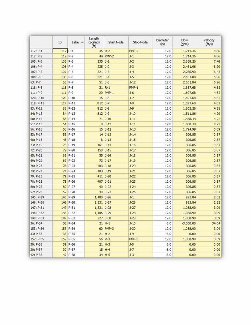
4.4 Modeling Results The computer software Bentley WaterCAD V8i (Select Series 6) was used to analyze the proposed water system for RSID. The analysis was based on the raw test data from the flow test results shown in Appendix A (Section 2.3) and design criteria discussed in Section 4.1. The raw flow data was used to generate the three pump curves to simulate the pressure being supplied to the system with a 10% safety factor applied. The water system supply was modeled as a constant pressure source for each scenario using a reservoir and pump to simulate the pressure being supplied to the system at each tie-in location and at a hydrant at the Sundance Subdivision to the west of the site.
Van�Buren�Street

�
Roosevelt Street Improvement District Engineering Services Final Water Report
April 2017 City of Buckeye, AZ
��
The WaterCAD model was used to represent Normal Conditions (average day, maximum day, and peak hour) and Fire Flow (maximum day plus fire flow) conditions. Fire Flow conditions were modeled as 3,000 gpm for 4 hours. The WaterCAD model is shown in Appendix B. The model was designed to handle demands from future developments adjacent to the project area, for which the proposed system will supply water. All pipes in the network are 12” D.I.P. Under Normal Conditions (Peak Hour Demand), the minimum pressure in the proposed system is 54.63 psi and max velocity is 4.01 fps. For Fire Flow conditions, the worst case scenario (lowest pressures) was used. This occurs when the fire flow of 3,000 gpm was applied at hydrant H-1. Under Fire Flow conditions, the minimum pressure in the proposed system is 39.64 psi and max velocity is 7.48 fps.
5.0 CONCLUSION All pressures and velocities for the proposed water system are within the City Of Buckeye standards in both normal and fire flow scenarios. 12” water pipe will provide adequate flow and pressure for the proposed system. Future demand for the area north of I-10 was included in the design model. The complete WaterCAD output results are included in Appendix B. The pressures north of I-10 were greater than the minimum pressure of 50 psi, however our model was conservatively based on fire flow values of dead end lines. The residual pressures in these locations are expected to improve once the new system is in place. The developer will need to verify that pressures meet City of Buckeye standards when connected to the proposed system in the future. A booster pump may need to be designed to provide adequate flow to future developments north of I-10.
�
Roosevelt Street Improvement District Engineering Services Final Water Report
April 2017 City of Buckeye, AZ
��
6.0 REFERENCES
Engineering Design Standards, City of Buckeye – December 2012
Roosevelt Street Improvement District Engineering Services Final Water Report
April 2017 City of Buckeye, AZ
��
APPENDIX A – Fire Flows & Pump Curves
� �
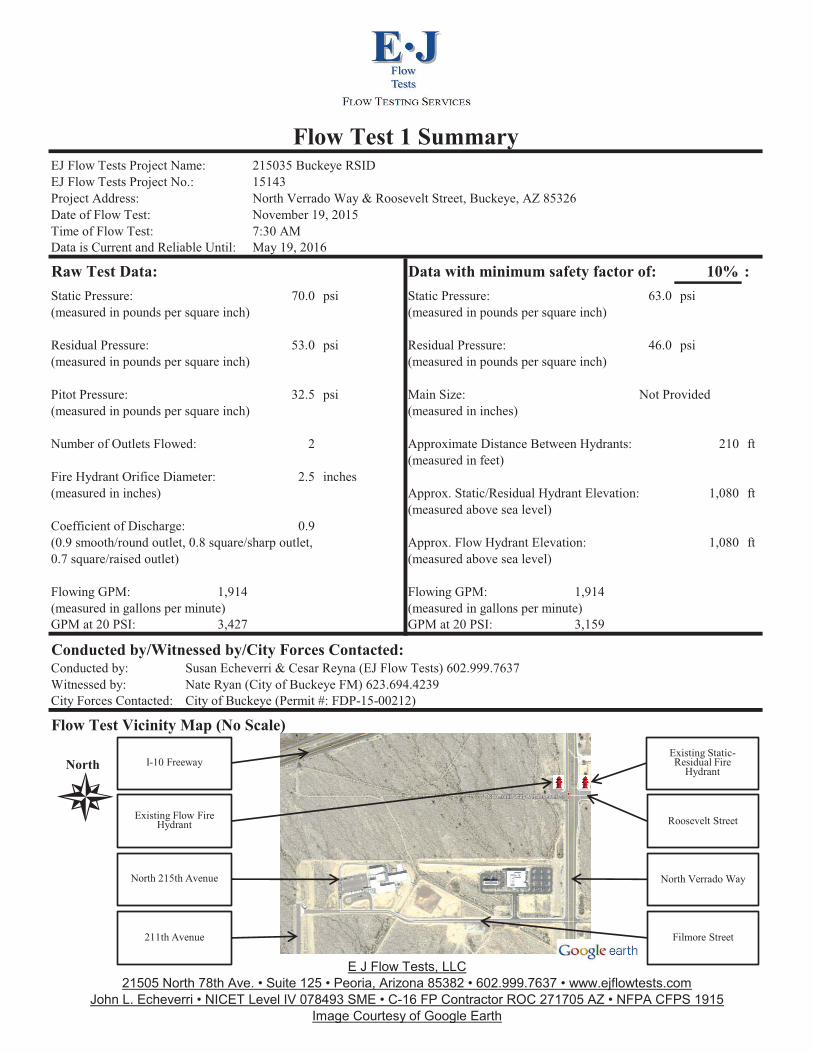
Raw Test Data: 10% :70.0 psi 63.0 psi
(measured in pounds per square inch) (measured in pounds per square inch)
53.0 psi 46.0 psi(measured in pounds per square inch) (measured in pounds per square inch)
32.5 psi (measured in pounds per square inch) (measured in inches)
2 210 ft(measured in feet)
2.5 inches (measured in inches) 1,080 ft
(measured above sea level)0.9
1,080 ft(measured above sea level)
1,914 1,914(measured in gallons per minute) (measured in gallons per minute)
3,427 3,159
Conducted by/Witnessed by/City Forces Contacted:
Flow Test Vicinity Map (No Scale)
North
Data is Current and Reliable Until:
Flow Test 1 SummaryEJ Flow Tests Project Name: EJ Flow Tests Project No.: Project Address:Date of Flow Test: Time of Flow Test:
Static Pressure:
Pitot Pressure:
City of Buckeye (Permit #: FDP-15-00212)
Fire Hydrant Orifice Diameter:
Coefficient of Discharge:
Flowing GPM:
GPM at 20 PSI:
Susan Echeverri & Cesar Reyna (EJ Flow Tests) 602.999.7637Nate Ryan (City of Buckeye FM) 623.694.4239
City Forces Contacted:
Conducted by:Witnessed by:
Approximate Distance Between Hydrants:
Approx. Static/Residual Hydrant Elevation:
GPM at 20 PSI:
215035 Buckeye RSID15143North Verrado Way & Roosevelt Street, Buckeye, AZ 85326November 19, 20157:30 AMMay 19, 2016
Data with minimum safety factor of:
Approx. Flow Hydrant Elevation:
Flowing GPM:
Static Pressure:
(0.9 smooth/round outlet, 0.8 square/sharp outlet, 0.7 square/raised outlet)
Residual Pressure:
Main Size:
Number of Outlets Flowed:
Residual Pressure:
Not Provided
Existing Flow Fire Hydrant
211th Avenue Filmore Street
North Verrado Way
Existing Static-Residual Fire
Hydrant I-10 Freeway
North 215th Avenue
Roosevelt Street
E J Flow Tests, LLC21505 North 78th Ave. • Suite 125 • Peoria, Arizona 85382 • 602.999.7637 • www.ejflowtests.com
John L. Echeverri • NICET Level IV 078493 SME • C-16 FP Contractor ROC 271705 AZ • NFPA CFPS 1915Image Courtesy of Google Earth
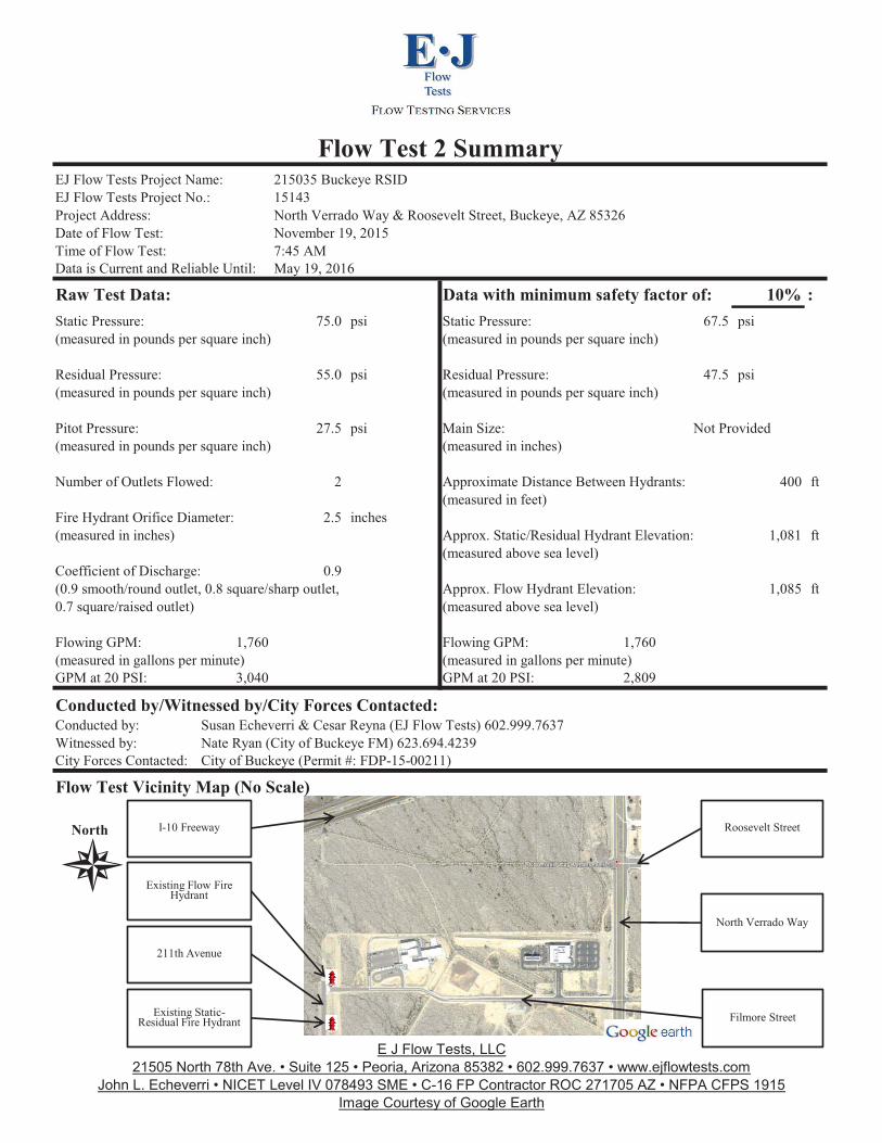
Raw Test Data: 10% :75.0 psi 67.5 psi
(measured in pounds per square inch) (measured in pounds per square inch)
55.0 psi 47.5 psi(measured in pounds per square inch) (measured in pounds per square inch)
27.5 psi (measured in pounds per square inch) (measured in inches)
2 400 ft(measured in feet)
2.5 inches (measured in inches) 1,081 ft
(measured above sea level)0.9
1,085 ft(measured above sea level)
1,760 1,760(measured in gallons per minute) (measured in gallons per minute)
3,040 2,809
Conducted by/Witnessed by/City Forces Contacted:
Flow Test Vicinity Map (No Scale)
North
Approx. Flow Hydrant Elevation:
Flowing GPM:
Static Pressure:
(0.9 smooth/round outlet, 0.8 square/sharp outlet, 0.7 square/raised outlet)
Residual Pressure:
Main Size:
Number of Outlets Flowed:
Residual Pressure:
Not Provided
215035 Buckeye RSID15143North Verrado Way & Roosevelt Street, Buckeye, AZ 85326November 19, 20157:45 AMMay 19, 2016
Data with minimum safety factor of:
City Forces Contacted:
Conducted by:Witnessed by:
Approximate Distance Between Hydrants:
Approx. Static/Residual Hydrant Elevation:
GPM at 20 PSI:
Static Pressure:
Pitot Pressure:
City of Buckeye (Permit #: FDP-15-00211)
Fire Hydrant Orifice Diameter:
Coefficient of Discharge:
Flowing GPM:
GPM at 20 PSI:
Susan Echeverri & Cesar Reyna (EJ Flow Tests) 602.999.7637Nate Ryan (City of Buckeye FM) 623.694.4239
Data is Current and Reliable Until:
Flow Test 2 SummaryEJ Flow Tests Project Name: EJ Flow Tests Project No.: Project Address:Date of Flow Test: Time of Flow Test:
Existing Flow Fire Hydrant
Existing Static-Residual Fire Hydrant Filmore Street
North Verrado Way
Roosevelt StreetI-10 Freeway
211th Avenue
E J Flow Tests, LLC21505 North 78th Ave. • Suite 125 • Peoria, Arizona 85382 • 602.999.7637 • www.ejflowtests.com
John L. Echeverri • NICET Level IV 078493 SME • C-16 FP Contractor ROC 271705 AZ • NFPA CFPS 1915Image Courtesy of Google Earth

EJ Project ID: Project Address: Date of Flow Test: Time of Flow Test: Data Reliable Until: Conducted By: Witnessed By: City Forces Contacted: Permit Number:
16081W Van Buren St, Buckeye, AZ, 853262016-05-057:36 AM2016-11-05Austin Gourley (EJ Flow Test) & Eder Cueva (EJ Flow Test)Nate Ryan (City of Buckeye Fire Department) 623.694.4239City of BuckeyeFDP-16-00142
Raw Flow Test Data: Static Pressure: 61.0 PSIResidual Pressure: 46.0 PSIFlowing GPM: 1,610GPM @ 20 PSI: 2,771Pitot Pressure One: 23 PSIHydrant Orifice Diameter: 2.5 inchesPitot Pressure Two: 23 PSIHydrant Orifice Diameter: 2.5 inchesCoefficient of Discharge: 0.9
Data with a 10 % Safety FactorStatic Pressure: 54.9 PSIResidual Pressure: 39.9 PSIFlowing GPM: 1,610GPM @ 20 PSI: 2,540
Static-Residual Hydrant
Flow Hydrant
Distance Between Hydrants808 ft (measured linearly)
Static-Residual Elevation1114 ft (above sea level)
Flow Hydrant Elevation1117 ft (above sea level)
Elevation & distance values are approximate
EJ Flow Tests, LLC21505 North 78th Ave. | Suite 125 | Peoria, Arizona 85382 | (602) 999-7637 | www.ejengineering.com
John L. Echeverri | NICET Level IV 078493 SME | C-16 FP Contractor ROC 271705 AZ | NFPA CFPS 1915
Page 1 of 2

PUMP CURVE 1
0
10
20
30
40
50
60
70
0.0
20.0
40.0
60.0
80.0
100.0
120.0
140.0
160.0
0 500 1000 1500 2000 2500 3000 3500
Pres
sure
, P (p
si)
Hea
d, H
(ft)
Flow Rate, Q (gpm)
Pump Curve Extrapolated from Fire Flow Test Results

PUMP CURVE 2
0
10
20
30
40
50
60
70
80
0.0
20.0
40.0
60.0
80.0
100.0
120.0
140.0
160.0
180.0
0 500 1000 1500 2000 2500 3000
Pres
sure
, P (p
si)
Hea
d, H
(ft)
Flow Rate, Q (gpm)
Pump Curve Extrapolated from Fire Flow Test Results

PUMP CURVE 3
0
10
20
30
40
50
60
0.0
20.0
40.0
60.0
80.0
100.0
120.0
140.0
0 500 1000 1500 2000 2500 3000
Pres
sure
, P (p
si)
Hea
d, H
(ft)
Flow Rate, Q (gpm)
Pump Curve Extrapolated from Fire Flow Test Results
�
Roosevelt Street Improvement District Engineering Services Final Water Report
April 2017 City of Buckeye, AZ
��
�
APPENDIX B – Link/Node Map & WaterCAD Results
�

AREA 1
AREA 2
AREA 3
AREA 4
AREA 5

WATERCAD RESULTS – NORMAL CONDITION (AVERAGE DAY DEMAND)

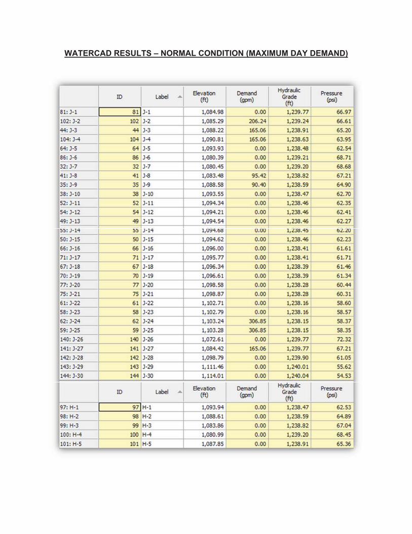
WATERCAD RESULTS – NORMAL CONDITION (MAXIMUM DAY DEMAND)


WATERCAD RESULTS – NORMAL CONDITION (PEAK HOUR DEMAND)


WATERCAD RESULTS – FIRE FLOW CONDITION (MAXIMUM DAY DEMAND)