final year project 2 produce electricity nurul …umpir.ump.edu.my/id/eprint/7624/1/cd7739.pdf ·...
TRANSCRIPT

FINAL YEAR PROJECT 2
ENERGY CONVERSION FROM DC GENERATOR PART IN WIND TURBINE TO
PRODUCE ELECTRICITY
NURUL HAFIZAH BINTI ABDULLAH HASIM
FB09048
Report submitted in fulfillment of the requirements for the award of the degree of
Bachelor of Manufacturing Engineering
FACULTY OF MANUFACTURING ENGINEERING
UNIVERSITY MALAYSIA PAHANG
JUNE 2013
vi
ABSTRACT
A wind turbine is a rotating machine which converts the kinetic energy of wind into
mechanical energy. If the mechanical energy is used directly by machinery, such as a
pump or grinding stones, the machine is usually called a windmill. If the mechanical
energy is instead converted to electricity, the machine is called a wind generator, or
more commonly called a wind turbine. This study presents of doing an experiment of a
simple wind turbine. The project is to analyze the suitable DC motor that can act as
generator part in wind turbine and operate properly. Besides that, the wind turbine
should generate electricity as it functions. For this process, after choosing the suitable
DC generator, an experiment was undergone to determine the output voltage which is
the electricity and also to check whether the DC generator operates properly. Actually
the experiment was undergone using wind velocity that can be gain around us but
because the wind velocity is too slow and not windy, I am using the wind velocity from
fan and act as the alternative method to undergo the experiment. So to make sure that all
the objectives for the Projek Sarjana Muda is achieved, the experiment and procedure
must be done properly and also by referring the scope of the project.

vii
ABSTRAK
Sebuah turbin angin adalah sebuah mesin berputar yang menukarkan tenaga kinetik
angin kepada tenaga mekanikal. Jika tenaga mekanikal digunakan secara langsung oleh
jentera, seperti pam atau batu pengisar, mesin biasanya dipanggil kincir angin. Jika
tenaga mekanikal sebaliknya ditukar kepada elektrik, mesin dipanggil penjana angin,
atau lebih dikenali sebagai turbin angin. Kajian ini membentangkan menjalankan
eksperimen turbin angin mudah. Projek ini adalah untuk menganalisis motor DC yang
sesuai yang boleh bertindak sebagai sebahagian penjana dalam turbin angin dan
beroperasi dengan betul. Selain itu, turbin angin yang perlu berfungsi perlu menjana
elektrik. Untuk proses ini, selepas memilih penjana DC yang sesuai, eksperimen telah
dijalankan untuk menentukan keluaran arus voltan elektrik dan juga untuk memeriksa
sama ada penjana DC beroperasi dengan betul. Sebenarnya eksperimen telah dijalnkan
menggunakan halaju angin yang boleh terdapat di sekeliling kita tetapi oleh kerana
halaju angin yang terlalu perlahan dan tidak berangin, saya menggunakan halaju angin
dari kipas angin dan bertindak sebagai kaedah alternatif untuk menjalani eksperimen.
Jadi untuk memastikan bahawa semua objektif untuk Projek Sarjana Muda dicapai,
eksperimen dan prosedur perlu dilakukan dengan betul dan juga dengan merujuk skop
projek.
viii
TABLE OF CONTENT
PAGE
SUPERVISOR’S DECLARATION ii
STUDENTDECLARATION iii
DEDICATION iv
ACKNOWLEDGEMENT v
ABSTRACT vi
ABSTRAK vii
TABLE OF CONTENT viii
LIST OF FIGURES xii
LIST OF TABLES xiii
LIST OF SYMBOLS xiv
CHAPTER 1 INTRODUCTION
1.1 Project Background 1
1.2 Problem Statement 3
1.3 Objectives 3
1.4 Scope of Study 3
ix
CHAPTER 2 LITERATURE REVIEW
2.0 Description 4
2.1 Experiment 4
2.2 Theoretical Analysis 5
2.3 Wind Turbine Research 6
2.4 Advantage Of Wind Turbine 7
2.5 Small Wind Turbine 8
2.5.1 Basic Component 9
2.5.2 Permanent DC Motor 10
2.5.3 Permanent Magnet Generator 11
2.5.4 Low-Speed Direct Drive Permanent 13
Synchronous Generators
2.5.5 Emulator Construction 14
2.5.6 Variable Shaft Speed Operation
2.6 Summary 15
CHAPTER 3 METHODOLOGY
3.1 Overall Methodology 17
3.2 Literature Review 17
3.3 Complete Wind Turbine System 18
3.4 Block Diagram 18
3.5 Flow of Development 19

x
3.6 Experiment Procedures 20
3.6.1 Dc Generator 21
3.6.2 Multi-Meter 22
3.6.3 Light Emitting Diode 24
3.7 Experimental Set-Up 25
3.7.1 Dc Motor (Generator)‟s Testing 26
– Without Load
3.7.2 Dc Motor (Generator)‟s Testing 26
– With Load
CHAPTER 4 RESULT AND ANALYSIS
4.1 Introduction 27
4.2 Theoretical Result 27
4.3 Experimental Result 28
4.4 Data Recorded 29
4.5 Output Voltage Vs Distance 29
4.5.1 Output Voltage With No Load Graph 30
4.5.2 Output Voltage With Load Graph 31
4.6 Discussions 32

xi
CHAPTER 5 CONCLUSIONS AND RECOMMENDATION
5.1 Introduction 35
5.2 Conclusions 35
5.3 Recommendation 36
REFERENCES 37
APPENDICES
A1 Final Year Project 1 Gantt Chart 40
A2 Final Year Project 2 Gantt Chart 41
xii
LIST OF FIGURES
Figure No Title Page
Figure 2.1 Wind Turbine Close Up 8
Figure 2.2 Principle Of A Rotating Dc Machine 10
Figure 2.3 AC/DC/AC Power Electronic Interfaces For A 12
Wind Generator
Figure 2.4 Typical Structures Of Gearbox Generator (a) And 12
Direct-Drive Generator (b) Of A Wind Plant
Figure 2.5 Wind Turbine System 14
Figure 2.6 Wind Turbine Simulator System 14
Figure 3.1 Block Diagram 18
Figure 3.2 Flow Of Development 19
Figure 3.3 12V DC Generator 21
Figure 3.4 Multimeter 21
Figure 3.5 Light Emitting Diode 23
Figure 3.6 Experimental Set-Up 25
Figure 4.1 Output Voltage With No Load 30
Figure 4.2 Output Voltage With Load 31
xiii
LIST OF TABLES
Table No Title Page
Table 3.1 List Of Component 20
Table 4.1 Data Recorded 29

xiv
LIST OF SYMBOLS
T = rotor torque
B = magnetic flux
R = average winding radius
l = effective conductor length (stack length)
Z = number of conductors
i = current flowing in the conductor
V = induced voltage
vy = velocity of inductor perpendicular to the magnetic field
Bx = magnetic flux vector
RPM = rotation per minute
ω = angular velocity
P = power

1
CHAPTER 1
INTRODUCTION
1.1 PROJECT BACKGROUND
“Wind energy” or “wind power” describes the process which is used wind to
generate mechanical power. This mechanical power can be used for specific tasks or a
generator can convert this mechanical power into electricity to power homes. Wind
turbines turn in the moving air and power on electric generator that supplies an electric
current.
Wind turbine work is like a fan but fan using electricity to make wind, however
wind turbines turns the blade which spin a shaft, then connects to generator and lastly it
will makes electricity. In energy-generating windmills, the shaft is connected to an
induction generator inside the structure. The wind turns the fans, which provides the
kinetic energy to spin the wires in the generator
Wind power means using the wind - harnessed by either a turbine, wind mill,
wind pump or even sails (for ships) - to generate the desired amount of electricity to be
used for home and commercial purposes. This provides an efficient power alternative
that is clean, abundant and completely environmentally friendly. This means that a
natural resource is used to produce clean, environmentally friendly power.
The most common ways of harnessing the power of the wind is using sails to
propel ships and sail boats across the water. The most desirable way of using the wind
to generate electricity is by erecting wind turbines.

2
There are two categories of wind turbines: the horizontal axis design (HAWT)
and the vertical axis design (VAWT). Since it is the more practical and popular, the
HAWT enjoys more attention than its sibling, the VAWT.
The HAWT has its main rotor shaft at the top of the column along with the
electrical generator. The turbines must be pointed into the wind and is positioned
favourably by either a small weathervane or a wind sensor. The rotor shaft and gearbox
of the VAWT are positioned vertically and are also installed near the ground. This
makes it more accessible for maintenance and other necessary adjustments. One of the
reasons why this type of wind turbine is less popular is that it can produce what is
known as pulsating torque.
As the wind turns the blades of the turbine they, in turn, turn the shafts running
down the tower and are connected to a generator. The working of the shafts and the
friction of the turning shafts link into the generator which then converts the energy
created by the wind turbine into the useful electricity that is needed.
Windmills works in 3 parts :-
1) Blades (the parts that look like fan) - “catch” the wind. Sitting at a slight angle
to the direction of the wind, the blades are pushed in a circle as the wind blows
against them.
2) Hub of the windmill – like the hub of a wheel, with the fans sticking out likes
spokes around it. Then the fans turn the hub as they move in a circle.
3) The part where hub is attached to the shaft, which spins as the hub spins. The
shaft is connected to whatever mechanism the windmill is designed to turn such
as generator part.
3
After finish the blade part, the next part is induction generators. Windmills that
generate energy contain induction energy. It does not make energy, but rather
converts kinetic (physical) energy into electrical by spinning a wire within a
magnetic field, which causes an electrical current to flow through the wire.
1.2 PROBLEM STATEMENT
During the development of generator part for wind turbine, the analysis of each
element need to be criticized so that the specific component used can be known. The
details of type of material used also must consider in order determining the production
of generator part of wind turbine experiment. Therefore, analysis must be done in order
to know the strength and weakness of making the generator part in order to produce the
output voltage.
1.3 OBJECTIVE
The objectives of this study are:
To generate the DC permanent magnet motor as generator part in wind turbine.
To gain the output power from the shaft rotation of DC permanent magnet
motor.
1.4 SCOPE OF STUDY
Literature review and study of wind turbine generator.
Research and analysis component that use in generator part.

4
CHAPTER 2
LITERATURE REVIEW
2.0 DESCRIPTION
Literature review and research on theories related to the projects begin after the
title of project was decided. These involve theories of numerous of wind turbine by
obtaining most of the information from the internet and a few reference book. Small
scale wind turbine was chosen to be developed in this project because it was relevant
based on size and cost involved.
2.1 EXPERIMENT
F. Wang, L. Bai, J. Fletcher, J. Whiteford, and D. Cullen (2007) studied on a
small domestic wind turbine with scoop. The aim of this study is to investigate the
possibility of improving wind energy capture, under low wind speed conditions, in a
built-up area, and the design of a small wind generator for domestic use in such
areas.The activities reported in this paper are optimization of a scoop design and
validation of the CFD model. The final design of scoop boosts the air flow speed by a
factor of 1.5 times equivalent to an increase in power output of 2.2 times with the same
swept area. Wind tunnel tests show that the scoop increases the output power of the
wind turbine. The results also indicate that, by using a scoop, energy capture can be
improved at lower wind speeds. The power generation of such a new wind turbine is
expected to be increased, particularly at locations where average wind speed is lower
and more turbulent.

5
A.K. Wright and D.H. Wood (2007) analyze that the magnitude of gyroscopic
rotor shaft and blade bending moments on a free yaw wind turbine rotor are
proportional to the product of rotor speed and yaw rate. An analysis is presented of the
relationship between two variables and wind speed, based on field test data from a 2 m
diameter wind turbine with a tail-fin furling system, and in reference to the recent
revision of the International Electro technical Commission standard for small wind
turbine design. Examples are given of fast yaw rates caused by furling, and by large
wind direction changes at relatively small wind and rotor speeds. Analyses of data
showed that reducing turbine yaw moment of inertia increases the magnitude of
maximum yaw rate for a given rotor speed, and that yaw rate is highly influenced by tail
fin aerodynamics.
2.2 THEORETICAL ANALYSIS
S. Roy (1997) studied on optimal planning of wind energy conversion systems
over an energy scenario. The wind power system design must optimize the annual
energy capture at a given site. The only operating mode for extracting the maximum
energy is to vary the turbine speed with varying wind speed such that at all times the
TSR is continuously equal to that required for the maximum power coefficient. The
theory and field experience indicate that the variable-speed operation yields 20 to 30%
more power than with the fixed-speed operation. In the system design, this trade-off
between energy increase and cost increase has to be optimized. In the past, the added
costs of designing the variable pitch rotor, or the speed control with power electronics,
outweighed the benefit of the increased energy capture. However, the falling prices of
power electronics for speed control and the availability of high-strength fiber
composites for constructing high-speed rotors have made it economical to capture more
energy when the speed is high.
6
J.S. Rohatgi and V. Nelson (1994) present the analysis for the generation of
wind power. Power regulation and control issues must be addressed in a modern
HAWT. When the wind speed increases to a value at which the generator is producing
rated power, some control action must occur so that the generator does not exceed its
rated capacity and overheat. Typical methods of power regulation at rated wind speed
are pitch regulation, stall regulation, and yaw control or furling. Pitch regulation is
accomplished by providing rotating bearings at the blade root and actively changing the
blade pitch angle relative to the wind, thus regulating power. Stall control is
accomplished by designing the rotor so that aerodynamic stall is reached at rated wind
speed and the rotor power is limited by airfoil stall. Yaw control or furling turns the
entire rotor out of the wind either vertically or horizontally at rated wind speed and
regulates power by reducing the rotor area exposed to the wind. The latter approach is
generally only employed on small wind turbines.
2.3 WIND TURBINE RESEARCH
Wind turbine is a rotating machine which converts the HT kinetic energy TH in
HT wind TH into HT mechanical energy. The developments of wind turbine start since
200 B.C which in Persia but until 250 A.D the usage of wind turbine had been
introduced by Roman Empire. In 7PthP century, the first vertical axle windmills had
been developing at Sistan, Afghanistan. These windmills had long vertical drive shafts
with rectangle shaped blades. It was made of six to twelve sails covered in reed matting
or cloth material and used to grind corn and draw up water and was used in the grist
milling and sugarcane industries.
Besides that, wind turbine technologies still grown up until 1908 at United
States. There have 72 wind-driven electric generators from 5 kW to 25 kW. The largest
machines were on 24 m (79 ft) towers with four-bladed 23 m (75 ft) diameter rotors.
Around the time of World War I, American windmill makers were producing 100,000
farm windmills each year, most for water-pumping.
7
However in 1954, the first utility grid-connected wind turbine operated was built
by the John Brown Company at Orkney Islands, United Kingdom. It had an 18 meters
diameter, three-bladed rotor and a rated output of 100 kW. From 1955 until nowadays,
every country want to used these technologies as alternative and renewal energy. More
developments and research have been done to use wind turbine as renewal energy
because have more advantages for natural. There have 3 level of range for the wind
turbine. They are large scale for 500 kW until 5 MW, medium scale between 10 kW
until 500 kW and the small scale is below than 10 kW.
2.4 ADVANTAGE OF WIND TURBINE
Wind for now is the renewable energy, that‟s why we use wind turbine energy
for resource and technology of choice. The most important is it was a “free” resource
and naturally. Also its a “clean” resource due to replacement of a “dirty” energy source
(coal) and no emissions associated with its use. Wind turbine can be utilized on
underutilized land or on lands and currently in commodity crop production. Also which
is can be “harvest” on the surface and “harvest” above the surface. Then it will
primarily be used for electricity generation for immediate end-use.
Wind turbine one of the best choose that we have because it was no air
emissions and also don‟t have Greenhouse Gas Emissions. The most important is, it no
need for fuel to mine, transport, or store for the source. It also don‟t need any equipment
like cooling water that we always use at fuel engine and nuclear reactor. There are free
from making pollution for example water pollution that always produces by human
activity. After all there is no waste when used wind turbine.

8
2.5 SMALL WIND TURBINE
In this project, I need to build a prototype of inner component in the wind
turbine that can converting the energy of the wind into mechanical energy. Wind power
is the conversion of wind energy, such as using wind turbines to make electricity .
The vast majority of wind turbines consist of rotor blades which rotate around a
horizontal hub. The hub is connected to a gearbox and generator, which are located
inside the nacelle. The nacelle houses the electrical components and is mounted at the
top of the tower. In a grid-tied configuration the electricity from the generator is routed
to an inverter which converts the electricity from direct current (DC) to the alternating
current (AC) that electrical grids use. [3]
Figure 2.1 : Wind Turbine Close Up
System operation of wind turbine is when the rotor begins to rotate (spin) after
the wind speed reaches, the battery charging commences at a slightly higher speed,
depending on the battery state of charge. Then when the battery is fully charged, the
charge controller disconnects the turbine from the battery. The turbine will produces a
three phase alternating current (AC) that varies in voltage and frequency as the wind
speed varies. Next ,the controller (regulator) rectifies this AC into the direct current
(DC) required for battery charging and controls the energy supplied to the batteries to
avoid overcharging.
9
2.5.1 BASIC COMPONENT
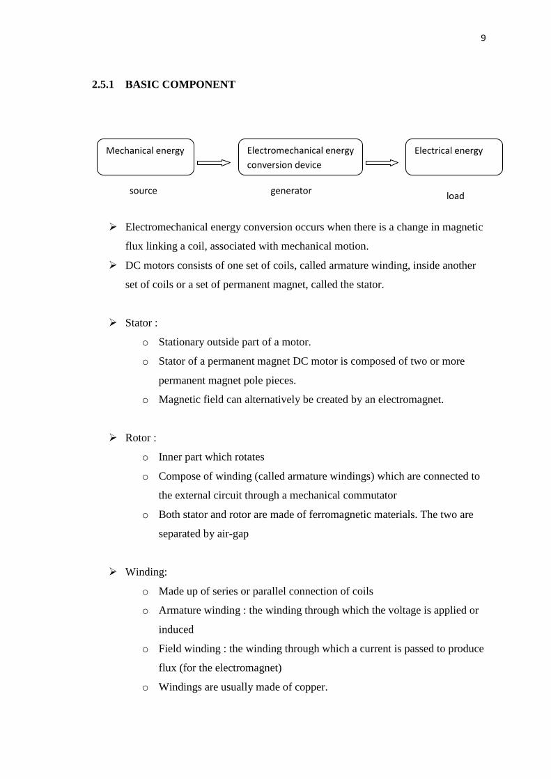
Electromechanical energy conversion occurs when there is a change in magnetic
flux linking a coil, associated with mechanical motion.
DC motors consists of one set of coils, called armature winding, inside another
set of coils or a set of permanent magnet, called the stator.
Stator :
o Stationary outside part of a motor.
o Stator of a permanent magnet DC motor is composed of two or more
permanent magnet pole pieces.
o Magnetic field can alternatively be created by an electromagnet.
Rotor :
o Inner part which rotates
o Compose of winding (called armature windings) which are connected to
the external circuit through a mechanical commutator
o Both stator and rotor are made of ferromagnetic materials. The two are
separated by air-gap
Winding:
o Made up of series or parallel connection of coils
o Armature winding : the winding through which the voltage is applied or
induced
o Field winding : the winding through which a current is passed to produce
flux (for the electromagnet)
o Windings are usually made of copper.
Mechanical energy Electromechanical energy
conversion device
Electrical energy
source generator load

10
2.5.2 PERMANENT DC MOTOR
Electromechanical energy conversion employing generators and motors play a
crucial role in energy consumption and production. Permanent magnet technology
represents a new enhanced area that can be used both in generators and motors.
Permanent magnet motors are well-known class of rotating and linear electric machines
used in both motoring and generating modes. Permanent magnet machine describes all
electromagnetic energy conversion devices in which the magnetic excitation is supplied
by a permanent magnet or several permanent magnets. The energy converters using
permanent magnet include a variety of configurations, and such terms as motor,
generator, alternator, stepper motor, linear motor, actuator and many others to describe
them.
A machine with a high torque or high power density and high efficiency at a low
design operating speed can be considered for the direct-drive wind turbine application.
A machine‟s ability to provide a significant reduction in the cost of converting wind
derived mechanical power to electric power by eliminating the geared speed increaser,
typically used into wind power applications. For this reason, the technology of low-
speed, high-torque motors requires scrupulous evaluation in order to determine their
suitability for a direct-drive wind turbine application.
Figure 2.2 : Principle Of A Rotating DC Machine

11
The principle can directly be used to develop a 2-pole rotating DC machine.
Motor as well generator operation can be derived from figure above. The collector or
commutator guarantees the un in directionality of the current.
We can use permanent magnet motors, because they are widely available,
reliable because of the nature of their construction, and start generating electricity at
almost any RPM. Inside a permanent magnet motor is a coil of wound copper
surrounded by permanent magnets. These type of motors rotate using electromagnetic
induction, which means electricity is supplied to wound copper wire which creates a
magnetic field. The magnetic field created by the electricity flowing through the copper
wire opposes the permanent magnets in the motor housing. As a result, the copper wire
that is attached to the shaft of the motor tries “to push” itself away from the permanent
magnets. So your motor starts spinning.
2.5.3 PERMANENT MAGNET GENERATOR
Random output variation is one of the significant characteristics of wind power.
With a PM generator coupled to a wind turbine, the voltage output will be varying with
its rotor speed because of the wind speed variation. A permanent magnet generator has
no excitation control and hence produces a voltage proportional to the shaft speed which
in turn varies with the wind speed. The earliest and still most widely used power
electronic circuit for this application uses an AC/DC/AC technology in which the
variable frequency, variable voltage from the generator is first rectified to DC and then
converted to AC and fed to the grid
12
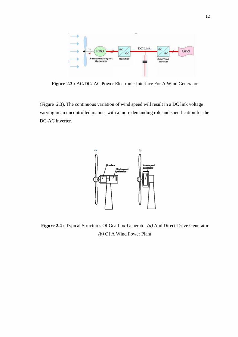
Figure 2.3 : AC/DC/ AC Power Electronic Interface For A Wind Generator
(Figure 2.3). The continuous variation of wind speed will result in a DC link voltage
varying in an uncontrolled manner with a more demanding role and specification for the
DC-AC inverter.
Figure 2.4 : Typical Structures Of Gearbox-Generator (a) And Direct-Drive Generator
(b) Of A Wind Power Plant

13
Permanent-magnet (PM) synchronous generators are one of the best solutions
for small-scale wind power plants. Low-speed multiple PM generators are
maintenance-free and may be used in different climate conditions. The use of a gearbox
causes many technological problems in a wind power plant, as it demands regular
maintenance, increases the weight of the wind plant, generates noise and increases
power losses. These problems may be avoided using an alternative – a direct-drive low-
speed PM synchronous generator (Fig. 2.4b).
2.5.4 LOW-SPEED DIRECT-DRIVE PERMANENT MAGNET
SYNCHRONOUS GENERATORS
In small-scale wind power plants very often low-speed direct-drive synchronous
generators are used. Due to low rotational speed of the synchronous generator directly
connected to the mechanical shaft of the wind rotor, the generator has a multiple
construction. A synchronous generator may be excited by traditional current-carrying
field winding or by permanent magnet system of high energy. Synchronous generators
with permanent magnet excitation for small-scale wind power units are more
maintenance-free and reliable in long-term exploitation. The generators were of a
conventional construction of a typical synchronous generator with radial magnetic flux
in the air gap between the inner rotor and the outer stator.[2] Alternator are designed to
charge (storage) batteries (accumulators). Then, the alternator converts the mechanical
(rotational) energy of the rotor into electricity (three phase alternating current). The
magnets are in the rotor, which allows suppression of the rings and brushes for
connection. The number of poles will improves the alternator performance at low speed,
increases the mechanical parts life and reduces the noise level. The rotor system allows
the efficient conversion of wind linear movement in to alternator rotational movement.
14
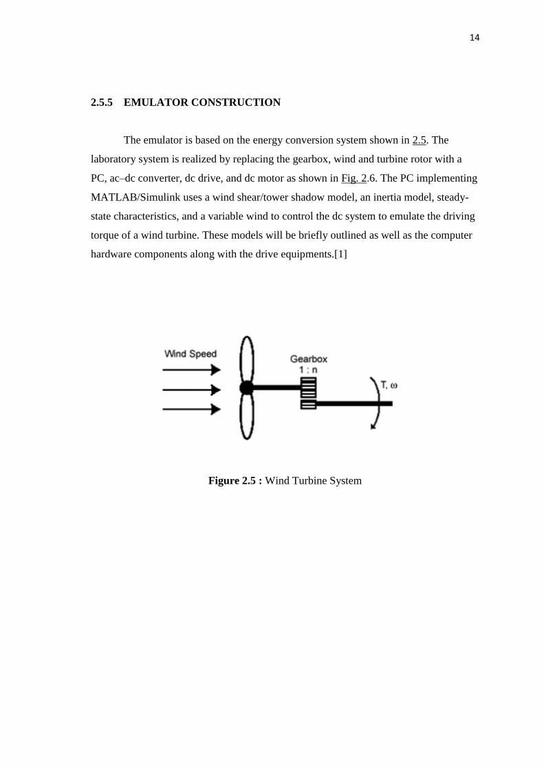
2.5.5 EMULATOR CONSTRUCTION
The emulator is based on the energy conversion system shown in 2.5. The
laboratory system is realized by replacing the gearbox, wind and turbine rotor with a
PC, ac–dc converter, dc drive, and dc motor as shown in Fig. 2.6. The PC implementing
MATLAB/Simulink uses a wind shear/tower shadow model, an inertia model, steady-
state characteristics, and a variable wind to control the dc system to emulate the driving
torque of a wind turbine. These models will be briefly outlined as well as the computer
hardware components along with the drive equipments.[1]
Figure 2.5 : Wind Turbine System

15
Figure 2.6 : Wind Turbine Simulator System
2.6.6 VARIABLE SHAFT SPEED OPERATION
In the wind turbine systems, the turbine is allowed to rotate at different speeds
with the varying wind speed. It is usually desired to ensure optimum power transfer.
The actual speed of rotation is determined by the torque versus speed characteristics of
both the turbine and the generator. In the operating mode, major control means are
inevitably placed on the electrical side. Obviously, the control of electrical systems is
easy to implement, more reliable and less costly than the control of mechanical systems.
In addition, synchronous machines may be used in variable shaft speed. In this case,
operation of the system at the most efficient working condition is possible.