finally
TRANSCRIPT

DTMF CONTROLLED SPY ROBOT AISSMS College of Engineering, Pune
TE Electronics Engineering, Academic Year 2014-15 1
CHAPTER 1
INTRODUCTION

DTMF CONTROLLED SPY ROBOT AISSMS College of Engineering, Pune
TE Electronics Engineering, Academic Year 2014-15 2
CHAPTER 1
INTRODUCTION
As interest in robotics continues to grow, robots are increasingly being integrated
into everyday life. The results of this integration are end-users possessing less and less
technical knowledge of the technology. For example, consider the application of mobile
robots in the health care industry, where the intended end users are patients themselves. In
this case, the need for simplified, reliable, and user-friendly robot designs is of almost
importance. Mobile phones today became very popular an essential entity for one and all
and so, for any mobile based application there is great reception. Wireless controlled
robots utilize RF circuits. However, the use of RF contributes to enhancing the already
mysterious nature of robotic technology, which had limitations like limited range, limited
frequency ranges and controls. But a mobile phone controlled robot can hold up these
limitations. It has a robust control, unlimited range (coverage area of the service
provider), and we can have as much as 12 controls.
1.1 OBJECTIVES
The main objectives of our project are
1. To control the wireless robot using DTMF technology.
2. For gas detection using MQ7 sensor in remote areas.
3. To use wireless robot for surveillances and spying purposes.
1.2 LITERATURE SURVEY
Conventionally, Wireless-controlled robots use RF circuits which have the
drawbacks of limited working range, limited frequency range and the limited controls.
Use of a mobile phones for robotic control can overcome these limitations. It provides the
advantage of robust control, working range as large as the coverage area of the service
provider, no interference with other controllers and up to twelve controllers.
Although the appearance and the capabilities of robots vary vastly, all robots share
the feature of a mechanical, movable structure under some form of control. The Control
of robot involves three distinct phases: perception, processing and action. Generally, the
preceptors are sensors mounted on the robot such as MQ7 smoke sensor, processing is
done by the on-board microcontroller or processor, and the task is performed using
DTMF CONTROLLED SPY ROBOT AISSMS College of Engineering, Pune
TE Electronics Engineering, Academic Year 2014-15 3
motors or with some other actuators. Man has come long way In terms of development
over a period of time we would use the RF modules for the purpose wireless after that we
overcome with the techniques of GSM modems and we use the DTMF in wireless
system.
The DTMF technology has overcome the problem of limitation which we can
work only in limited range or limited area was in RF technology by using cell phone
(DTMF). We can access our device or the robot as large as the working space of the
service provider, no interference with other controllers and up to 12 controls.
1.3 DTMF TECHNOLOGY
DTMF is a generic communication term for touch tone (a Registered Trademark
of AT&T). The tones produced when dialing on the keypad on the phone could be used to
represent the digits, and a separate tone is used for each digit. However, there is always a
chance that a random sound will be on the same frequency which will trip up the system.
It was suggested that if two tones were used to represent a digit, the likelihood of a false
signal occurring is ruled out.
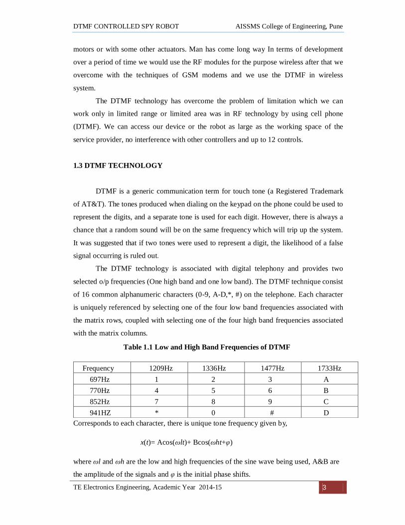
The DTMF technology is associated with digital telephony and provides two
selected o/p frequencies (One high band and one low band). The DTMF technique consist
of 16 common alphanumeric characters (0-9, A-D,*, #) on the telephone. Each character
is uniquely referenced by selecting one of the four low band frequencies associated with
the matrix rows, coupled with selecting one of the four high band frequencies associated
with the matrix columns.
Table 1.1 Low and High Band Frequencies of DTMF
Frequency 1209Hz 1336Hz 1477Hz 1733Hz 697Hz 1 2 3 A 770Hz 4 5 6 B 852Hz 7 8 9 C 941HZ * 0 # D
Corresponds to each character, there is unique tone frequency given by,
x(t)= Acos(ωlt)+ Bcos(ωht+φ)
where ωl and ωh are the low and high frequencies of the sine wave being used, A&B are
the amplitude of the signals and φ is the initial phase shifts.

DTMF CONTROLLED SPY ROBOT AISSMS College of Engineering, Pune
TE Electronics Engineering, Academic Year 2014-15 4
1.4 WIRELESS VIDEO SURVIELLANCE
In current state-of-the-art wireless video surveillance systems, each source node is
usually equipped with one or more cameras, a microprocessor, the storage unit, a
transceiver, and a power supply. The basic functions of each node include video capture,
video compression and data transmission. The process of video analysis for different
surveillance purposes is implemented either by the sender or by the receiver, depending
on their computational capability. The remote control unit at the receiver's end can also
provide some useful information feedback to the sender in order to enhance the system
performance.
IP Webcam turns an android phone into a network camera with multiple vewing
options The phone’s camera can be viewed on any platform with VLC player or web
browser. The video streaming can be done inside WiFi Network without internet access.
Here we are using the same phone for wireless video streaming which is going to detect
the DTMF tones sent by the end user. The video on the mobile camera is streamed on to
the PC or laptop by the end user.
The advantage of using this android application is that the cost of wireless camera
modules is eliminated and the user can have multiple viewing options and controls of the
camera from a remote location. This android application can take photos, record videos,
audios and change the camera’s resolution all from a remote location.

DTMF CONTROLLED SPY ROBOT AISSMS College of Engineering, Pune
TE Electronics Engineering, Academic Year 2014-15 5
CHAPTER 2
SPECIFICATIONS

DTMF CONTROLLED SPY ROBOT AISSMS College of Engineering, Pune
TE Electronics Engineering, Academic Year 2014-15 6
CHAPTER 2
SPECIFICATIONS
2.1 SPY ROBOT
Surveillance or spying involves individual obtaining information that is
considered secret or confidential without the permission of the holder of the information.
Spying area in military ground where enemy stay can be took before taking any action. A
robot is a virtual or mechanical artificial agent. In practice, it is usually an electro
mechanical system which, by its appearance or movements, conveys a sense that it has
intent or agency of its own
The DTMF controlled spy robot has been designed in such a way that it can fulfill
all the needs of military, police and also for personal security. It has countless application
and can be used in different environment and scenario. For instance, at one place it can be
used for bomb disposal squad, while at another application can be provide up to date
information in hostage situation.
2.2 FEATURES OF THE PROJECT
1. Effective in implementation.
2. Low cost.
3. Small Size.
4. Low maintenance.
5. Low power consumption.
6. Long control range due the use of DTMF technology.
7. Robot monitored from a remote area (no need of ‘line-of-sight’ arrangement).
8. Gas detection.
9. Buzzer indication (for alerting).
10. Video Surveillance using mobile’s camera.

DTMF CONTROLLED SPY ROBOT AISSMS College of Engineering, Pune
TE Electronics Engineering, Academic Year 2014-15 7
2.3 SPECIFICATIONS
1. Operating Range: Unlimited(as provided by service provider).
2. Power Supply: 12V, 1.3A battery .
3. Motors : 45 RPM
4. Project Size : 31.5cm x 27.5cm x 11 cm
5. Chassis : 29cm x 16 cm
6. Wheels Dimension: Diameter – 7cm
7. Smoke Sensor Sensitivity: 10-10000ppm CO.
8. Camera: a) Resolution - 8 Mega Pixel.
b) Range – 50 meters.
9. Android Applications : a) IP Webcam
b) Auto call receiver.

DTMF CONTROLLED SPY ROBOT AISSMS College of Engineering, Pune
TE Electronics Engineering, Academic Year 2014-15 8
CHAPTER 3
BLOCK DIAGRAM

DTMF CONTROLLED SPY ROBOT AISSMS College of Engineering, Pune
TE Electronics Engineering, Academic Year 2014-15 9
CHAPTER 3
BLOCK DIAGRAM
In this project the robot, is controlled by a mobile phone that makes call to the
mobile phone attached to the robot. In the course of the call, if any button is pressed, a
tone corresponding to the button pressed is heard at the other end of the call. This tone is
called ‘DUAL TONE MULTI-FREQUENCY’ (DTMF) tone. The robot receives this
DTMF tone with the help of phone stacked in the robot.
The received tone is processed by the PIC microcontroller with the help of DTMF
decoder MT8870. The decoder decodes the DTMF tone in to its equivalent binary digit
and this binary number is send to the microcontroller. The microcontroller is
preprogrammed to take a decision for any give input and outputs its decision to motor
drivers in order to drive the motors for forward or backward motion or a turn.
Fig. 3.1 Block Diagram

DTMF CONTROLLED SPY ROBOT AISSMS College of Engineering, Pune
TE Electronics Engineering, Academic Year 2014-15 10
3.1 DESCRIPTION
1) Remote Mobile:
The remote mobile is with the operator which is used to send DTMF tones on the
other mobile on the vehicle.
2) Receiver Mobile:
It is used to receive DTMF signals transmitted by the remote mobile.
3) DTMF Decoder:
The decoder decodes the DTMF tone into its equivalent Binary Digits & this
binary number is send to the microcontroller. It acts as an intermediate device between
receiver mobile and microcontroller to decode the DTMF tone in a compatible signal
accepted by microcontroller.
4) Microcontroller:
It processes on the DTMF signal and gives corresponding actions which is to be
taken by the motor driver on which the direction is controlled by the operator. The
Microcontroller is pre-programmed to take a decision for any given input & outputs its
decision to motor drivers in order to drive the motors for forward or backward motion or
a turn
5) Motor Driver:
Motor driver integrated circuit (IC) act as current amplifiers since they takes low-
current control signal and provide a higher-current signal. This higher current signal is
used to drive the motor.
6) Smoke Sensor(MQ7):
The Smoke Sensor will detect the smoke from surrounding environment and send
the data back to the microcontroller.
7) Buzzer:
The buzzer is used for indicating that smoke (CO) has been detected.
8) Camera:
The camera is used for spying purpose. The mobile’s camera can take pictures,
record video or show live streaming of the remote location.

DTMF CONTROLLED SPY ROBOT AISSMS College of Engineering, Pune
TE Electronics Engineering, Academic Year 2014-15 11
CHAPTER 4
SYSTEM DESIGN

DTMF CONTROLLED SPY ROBOT AISSMS College of Engineering, Pune
TE Electronics Engineering, Academic Year 2014-15 12
CHAPTER 4
SYSTEM DESIGN
4.1 CIRCUIT DIAGRAM
Fig. 4.1 Circuit Diagram

DTMF CONTROLLED SPY ROBOT AISSMS College of Engineering, Pune
TE Electronics Engineering, Academic Year 2014-15 13
4.1.1 Description
The important components of this robot are DTMF decoder, microcontroller and
motor driver. An MT8870 DTMF decoder IC is used here. MT8870 IC uses digital
counting techniques to detect and decode all the 16 DTMF tone pairs into a 4-bit code
output. The built-in dial tone rejection circuit eliminates the need of pre-filtering. The
correct 4-bit decode signal of the DTMF tone is transferred to (pin11) through (pin14)
outputs. The pin11 to pin14 of DTMF decoder are connected to the pins of
microcontroller (RB0 to RB3).The PIC16F876A is a low power, 8-bit CMOS
microcontroller based on the enhanced RISC architecture. Switch S1 is used for manual
reset. The microcontroller output is not sufficient to drive the dc motors, so current
drivers are required for motor rotation. The L298 is a quad, high-current, full-H driver
designed to provide bidirectional drive currents of up to 4A at voltages from 4.5V to 46V.
It makes it easier to drive the dc motors. The L298 consists of four drivers. Pins IN1
through IN4 and OUT1 through OUT4 are the input and output pins respectively, of
driver 1 through driver 4. Drivers 1 and 2, and driver 3 and 4 are enabled by enable pin
6(EN1) and pin11 (EN2), respectively. When enable input EN1 (pin6) is high, drivers 1
and 2 are enabled and the outputs corresponding to their inputs are active. Similarly,
enable input EN2 (pin11) enables drivers 3 and driver 4. In order to control the robot, a
call need to make to the cell phone attached to the toy car (through headphone) from any
phone, which sends DTMF tunes on pressing the numeric buttons. The cell phone in the
robot kept in ‘auto answer’ mode. So after a ring, the cell phone accepts the call. Now
particular button may press on the mobile phone for pre defined desired action. The
DTMF tones thus produced are received by the cell phone in the car. These tones are fed
to the circuit by headset of the cell phone. The MT8870 decodes the received tone and
sends the equivalent binary number to the microcontroller. According to the program in
the microcontroller, the car starts moving. When the number key ‘2’ (binary equivalent
00000010) is pressed on the mobile phone. Port pins RA0 and RA3 drive motors M1 and
M2 in forward direction (as per table). Similarly, stop condition as per the condition.
Details conditions are shown in the flow chart diagram.
The primary objective of this project was to build a cell phone link between a
transmitter and a robot and provide the capability to operate the car from a remote
location. The purpose of using the cell phone was to make the operation possible from
any remote location in the world where cell phone use is available. The product would

DTMF CONTROLLED SPY ROBOT AISSMS College of Engineering, Pune
TE Electronics Engineering, Academic Year 2014-15 14
include two interface systems. One interface would operate between the transmitter and a
sending cell phone, and a second interface would operate between the receiving cell
phone and the dumb car. The interface on the sending side would allow production and
encoding of signals suitable for transmission via a cell phone. The interface on the
receiving end would process the signals received by the cell phone and control the robot.
The output on the Q1 to Q4 pins of the decoder IC has been shown in the image.
Fig. 4.2 Output of DTMF Decoder
The output of the decoder IC then can be connected to a motor driver IC
like(L298) to drive some motors the Mobile phone connected can be called from
anywhere in the world and by pressing the keys the DTMF tones can be transmitted to the
receiving end mobile and hence any device connected can be operated globally.

DTMF CONTROLLED SPY ROBOT AISSMS College of Engineering, Pune
TE Electronics Engineering, Academic Year 2014-15 15
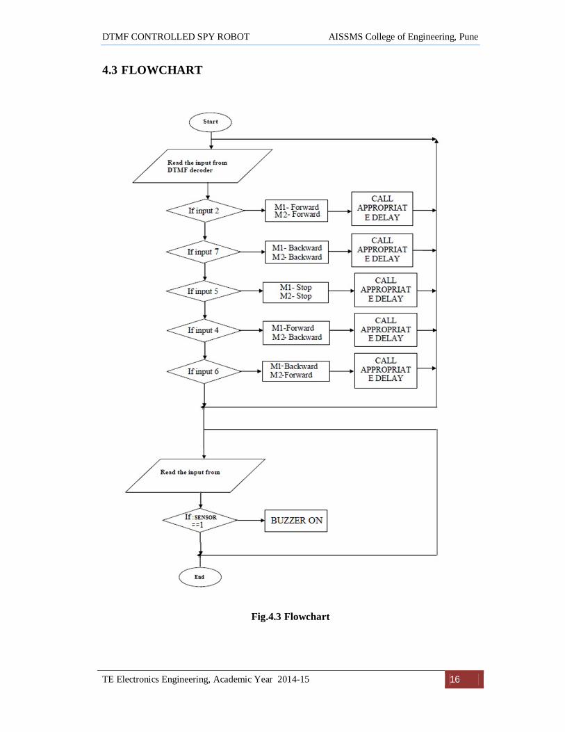
4.2 ALGORITHM
Step 1: Start
Step 2: Initialize PORT B as input port.
Step 3: Initialize PORTA and PORT C as output port.
Step 4: Take input from decoder IC MT8870 at PORT B
Step 5: If PORTB = 0b00000010 then goto forward( ) function then give some amount of
delay and goto STEP4.
Step 6: If PORTB = 0b00000111 then goto reverse( ) function then give some amount of
delay and goto STEP4.
Step 7: If PORTB = 0b00000100 then goto left ( ) function then give some amount of
delay and goto STEP4.
Step 8: If PORTB = 0b00000101 then goto stop ( ) function then give some amount of
delay and goto STEP4.
Step 9: If PORTB = 0b00000110 then goto right ( ) function then give some amount of
delay and goto STEP4.
Step 10: Take input from the Sensor at PORT C3
Step 11: If Sensor = = 1 then BUZZER ON.Step 12: Else BUZZER OFF.
DTMF CONTROLLED SPY ROBOT AISSMS College of Engineering, Pune
TE Electronics Engineering, Academic Year 2014-15 16
4.3 FLOWCHART
Fig.4.3 Flowchart

DTMF CONTROLLED SPY ROBOT AISSMS College of Engineering, Pune
TE Electronics Engineering, Academic Year 2014-15 17
4.4 PROGRAMMING
4.4.1 Using PICkit 2
The PICkit 2 Development Programmer/Debugger is a low-cost development
programmer. It is capable of programming most of Microchip’s Flash microcontrollers
and serial EEPROM devices.
One advantage of this programmer is that it does not require external power: it’s
powered from the USB cable. Another advantage is that you can often leave the
programmer connected while testing your circuit: no need to keep moving your chip back
and forth between the programmer and the breadboard.
Fig. 4.4 PICkit 2 Programmer Connector Pinout

DTMF CONTROLLED SPY ROBOT AISSMS College of Engineering, Pune
TE Electronics Engineering, Academic Year 2014-15 18
4.4.2 Code
#include <pic.h>
#define buzzer RC4
#define sensor RC3
#define motorr1 RA0
#define motorr2 RA1
#define motorl1 RA2
#define motorl2 RA3
void DelayMs (unsigned char cnt)
{
unsigned char i;
do {
i = 250;
do {
} while(--i);
} while(--cnt);
}
void forward()
{
motorr1 = 1;
motorr2 = 0;
motorl1 = 0;
motorl2 = 1;
}
void stop()
{
motorr1 = 0;
motorr2 = 0;
motorl1 = 0;

DTMF CONTROLLED SPY ROBOT AISSMS College of Engineering, Pune
TE Electronics Engineering, Academic Year 2014-15 19
motorl2 = 0;
}
void right()
{
motorr1 = 1;
motorr2 = 0;
motorl1 = 1;
motorl2 = 0;
}
void left()
{
motorr1 = 0;
motorr2 = 1;
motorl1 = 0;
motorl2 = 1;
}
void reverse()
{
motorr1 = 0;
motorr2 = 1;
motorl1 = 1;
motorl2 = 0;
void main(void)
{
char x,x1;
TRISB = 0x0F;
TRISA = 0x00;
TRISC = 0x08;
buzzer = 0;

DTMF CONTROLLED SPY ROBOT AISSMS College of Engineering, Pune
TE Electronics Engineering, Academic Year 2014-15 20
motorr1 = 0;
motorr2 = 0;
motorl1 = 0;
motorl2 = 0;
x1 = 0;
while(1)
{
read_new:
if(sensor == 0)
{
buzzer = 1;
}
else
{
buzzer = 0;
}
x = PORTB;
x = x & 0x0f;
if (x == x1)
{
goto read_new;
}
x1 = x;
if(x == 0b00000010)
{
stop();
DelayMs(100);
forward();
DelayMs(500);

DTMF CONTROLLED SPY ROBOT AISSMS College of Engineering, Pune
TE Electronics Engineering, Academic Year 2014-15 21
}
else if(x == 0b00000100)
{
stop();
DelayMs(100);
left();
DelayMs(500);
}
else if(x == 0b00000110)
{
stop();
DelayMs(100);
right();
DelayMs(500);
}
else if(x == 0b00000111)
{
stop();
DelayMs(100);
reverse();
DelayMs(500);
}
else if(x == 0b00000101)
{
stop();
DelayMs(500);
}
}
}

DTMF CONTROLLED SPY ROBOT AISSMS College of Engineering, Pune
TE Electronics Engineering, Academic Year 2014-15 22
CHAPTER 5
SELECTION OF
COMPONENTS

DTMF CONTROLLED SPY ROBOT AISSMS College of Engineering, Pune
TE Electronics Engineering, Academic Year 2014-15 23
CHAPTER 5
SELECTION OF COMPONENTS 5.1 HARDWARE SELECTION:
PIC Microcontroller
DTMF Decoder
Cell Phones
12 V DC Motors
Motor Driver
Buzzer
Smoke Sensor(MQ7)
Battery
3.5mm audio cable (for connecting mobile to DTMF module)
Crystal Oscillator
Resistors
Capacitors
Connectors
Wheels
Chassis
LED
PICKIT 2 Programmer
5.2 MICROCONTROLLER(PIC16F876A)
All PIC® microcontrollers employ an advanced RISC architecture. PIC16F8X
devices have enhanced core features, eight-level deep stack, and multiple internal and
external interrupt sources. The separate instruction and data buses of the Harvard
architecture allow a 14-bit wide instruction word with a separate 8-bit wide data bus. The
two stage instruction pipeline allows all instructions to execute in a single cycle, except
for program branches (which require two cycles). A total of 35 instructions (reduced
instruction set) are available. Additionally, a large register set is used to achieve a very
high performance level.

DTMF CONTROLLED SPY ROBOT AISSMS College of Engineering, Pune
TE Electronics Engineering, Academic Year 2014-15 24
5.2.1 Description
PIC is a family of modified Harvard architecture microcontrollers made by
Microchip Technology, derived from the PIC1650 originally developed by General
Instrument’s Microelectronics Division. The name PIC initially referred to Peripheral
Interface Controller. The first parts of the family were available in 1976; by 2013 the
company had shipped more than twelve billion individual parts, used in a wide variety of
embedded systems. The manufacturer supplies computer software for development
known as MPLAB, assemblers and C/C++ compilers, and programmer/debugger
hardware under the MPLAB and PICKit series. Third party and some open-source tools
are also available. Some parts have in-circuit programming capability; low-cost
development programmers are available as well has high-production programmers.
PIC devices are popular with both industrial developers and hobbyists due to their
low cost, wide availability, large user base, extensive collection of application notes,
availability of low cost or free development tools, serial programming, and re-
programmable Flash-memory capability.
5.2.2 Features:
High-Performance RISC CPU:
1. Only 35 single-word instructions to learn
2. All single-cycle instructions except for program branches, which are two-
cycle.
3. Operating speed: DC – 20 MHz clock input
4. DC – 200 ns instruction cycle
5. Up to 8K x 14 words of Flash Program Memory
6. Synchronous Serial Port (SSP) with SPI™
7. (Master mode) and I2C™ (Master/Slave)
Analog Features:
1. 10-bit, up to 8-channel Analog-to-Digital Converter (A/D)
2. Brown-out Reset (BOR)
3. Analog Comparator module with:
a. Two analog comparators
b. Programmable on-chip voltage reference (VREF) module

DTMF CONTROLLED SPY ROBOT AISSMS College of Engineering, Pune
TE Electronics Engineering, Academic Year 2014-15 25
c. Programmable input multiplexing from device.
Special Microcontroller Features:
1. 100,000 erase/write cycle Enhanced Flash program memory typical
2. 1,000,000 erase/write cycle Data EEPROM memory typical
3. Data EEPROM Retention > 40 years
4. Self-reprogrammable under software control
5. In-Circuit Serial Programming™ (ICSP™) via two pins
6. Single-supply 5V In-Circuit Serial Programming
7. Watchdog Timer (WDT) with its own on-chip RC oscillator for reliable
operation
8. Programmable code protection
9. Power saving Sleep mode.
CMOS Technology:
1. Low-power, high-speed Flash/EEPROM technology
2. Fully static design
3. Wide operating voltage range (2.0V to 5.5V)
4. Commercial and Industrial temperature ranges
5. Low-power consumption
Fig. 5.1 Pin Diagram of PIC16F876A

DTMF CONTROLLED SPY ROBOT AISSMS College of Engineering, Pune
TE Electronics Engineering, Academic Year 2014-15 26
5.3 DTMF RECEIVER AND DECODER(MT8870D) The 8870D/8870D-1 is a complete DTMF receiver integrating both the band split
Filter and digital decoder functions. The filter section uses switched capacitor techniques
for high and low group filters; the decoder uses digital counting techniques to detect and
decode all 16 DTMF tone pairs into a 14 bit code. External component count is
minimized by on chip provision of a differential input amplifier, clock oscillator and
latched three state bus interface.
5.3.1 Features
1. Complete DTMF receiver
2. Low power consumption
3. Internal gain setting amplifier
4. Adjustable guard time
5. Central office quality
6. Power down mode
7. Inhibit mode
8. Backward compatible with 8870C/8870C-1
Fig. 5.2 Pin Diagram of MT8870

DTMF CONTROLLED SPY ROBOT AISSMS College of Engineering, Pune
TE Electronics Engineering, Academic Year 2014-15 27
5.3.2 Pin Description
Table no. 5.1 MT8870 Pin Function
PIN NA DESCRIPTION 1 IN+ Non-Inverting Op-Amp (Input). 2 IN- Inverting Op-Amp (Input). 3 GS Gain Select. Gives access to output of front end differential
amplifier for connection of feedback resistor.
4 VRef Reference Voltage (Output).Nominally VDD/2 is used to bias inputs at mid-rail
5 INH Inhibit (Input). Logic high inhibits the detection of tones representing characters A, B, C
6 PWDN Power Down (Input). Active high. Powers down the device and inhibits the oscillator. This pin input is internally pulled down.
7 OSC1 Clock (Input).
8 OSC2 Clock (Output). A 3.579545 MHz crystal connected between pins OSC1 and OSC2 completes the internal oscillator circuit.
9 VSS Ground (Input). 0V typical.
10 TOE Three State Output Enable (Input). Logic high enables the outputs Q1-Q4. This pin is pulled up internally.
11-14 Q1-Q4 Three State Data (Output). When enabled by TOE, provide the code corresponding to the last valid tone pair received (seeTable1). When TOE is logic low, the data outputs are high impedance.
15 StD Delayed Steering (Output).Presents a logic high when a received tone-pair has been registered and the output latch up dated ;returns to logic low when the voltage on St/GT falls below VTSt.
16 ESt Early Steering (Output). Presents a logic high once the digital algorithm has detected a valid tone pair (signal condition). Any momentary loss of signal condition will cause ESt to return to a logic low.
17 St/GT Steering Input/Guardtime (Output)Bidirectional. A voltage greater thanVTSt detected at St causes the device to register the detected tone pair and update the output latch. A voltage less than VTSt frees the device to accept a new tone pair. The GT output acts to reset the external steering time-constant; its state is a function of ESt and the voltage on St.
18 VDD Positive power supply (Input). +5V typical.

DTMF CONTROLLED SPY ROBOT AISSMS College of Engineering, Pune
TE Electronics Engineering, Academic Year 2014-15 28
Table 5.2 Decoder Output for Corresponding Key Press
Flow Fhigh Key TOE Q4 Q3 Q2 Q1
697 1209 1 H 0 0 0 1
697 1336 2 H 0 0 1 0
697 1477 3 H 0 0 1 1
770 1209 4 H 0 1 0 0
770 1336 5 H 0 1 0 1
770 1477 6 H 0 1 1 0
852 1209 7 H 0 1 1 1
852 1336 8 H 1 0 0 0
852 1477 9 H 1 0 0 1
941 1209 0 H 1 0 1 0
941 1336 * H 1 0 1 1
971 1477 # H 1 1 0 0
697 1633 A H 1 1 0 1
770 1633 B H 1 1 1 0
852 1633 C H 1 1 1 1
941 1633 D H 0 0 0 0
- - ANY L Z Z Z Z
5.4 MOTOR DRIVER
There are some main factors to choose a microcontroller for any application.
They are:
1. Supply Voltage (Vs)
2. Input Voltage (Vi)
3. Peak Output Current (Io)
4. Power Dissipation (PD)
5. Protection (Over-temperature)
Different motor drivers have different Peak Output Current. In some motor
drivers, the logical supply voltage (Vss) is same Supply Voltage (Vs). The Enable pin
must be always high. The needs of current and voltage are determined by the application.

DTMF CONTROLLED SPY ROBOT AISSMS College of Engineering, Pune
TE Electronics Engineering, Academic Year 2014-15 29
The L298 is an integrated monolithic circuit in a 15-lead Multiwatt and
PowerSO20 packages. It is a high voltage, high current dual full-bridge driver designed to
accept standard TTL logic levels and drive inductive loads such as relays, solenoids, DC
and stepping motors. Two enable inputs are provided to enable or disable the device
independently of the input signals. The emitters of the lower transistors of each bridge are
connected together and the corresponding external terminal can be used for the
connection of an external sensing resistor. An additional supply input is provided so that
the logic works at a lower voltage.
Fig. 5.3 Pin Diagram of L298
5.4.1 Pin Description
Table 5.2 L298 Pin Functions
MW.15 Name Function
1;15
Sense A;
Sense B
Between this pin and ground is connected the sense resistor to
control the current of the load.
2;3 Out 1; Out 2
Outputs of the Bridge A; the current that flows through the
load connected between these two pins is monitored at pin 1.
4 VS
Supply Voltage for the Power Output Stages. A non-inductive
100nF capacitor must be connected between this pin and
DTMF CONTROLLED SPY ROBOT AISSMS College of Engineering, Pune
TE Electronics Engineering, Academic Year 2014-15 30
ground.
5;7
Input 1; Input
2 TTL Compatible Inputs of the Bridge A.
6;11
Enable A;
Enable B
TTL Compatible Enable Input: the L state disables the bridge
A
(enable A) and/or the bridge B (enable B).
8 GND Ground.
9 VSS
Supply Voltage for the Logic Blocks. A100nF capacitor must
be connected between this pin and ground.
10; 12
Input 3; Input
4 TTL Compatible Inputs of the Bridge B.
13; 14 Out 3; Out 4
Outputs of the Bridge B. The current that flows through the
load connected between these two pins is monitored at pin 15.
5.4.2 Specifications of L298:
1. Driver power supply: +5V~+46V
2. Driver Io: 2A
3. Logic power output Vss: +5~+7V (internal supply +5V)
4. Logic current: 0~36mA
5. Controlling level: Low -0.3V~1.5V, high: 2.3V~Vss
6. Enable signal level: Low -0.3V~1.5V, high: 2.3V~Vss
7. Max power: 25W (Temperature 75 Celsius)
8. Working temperature: -25C~+130C
9. Dimension: 60mm*54mm
5.4.3 H-Bridge Circuit
An H bridge is an electronic circuit which enables a voltage to be applied across a
load in either direction. These circuits are often used in robotics and other applications to
allow DC motors to run forwards and backwards.
The term H bridge is derived from the typical graphical representation of such a
circuit. An H bridge is built with four switches (solid-state or mechanical). When the
switches S1 and S4 are closed (and S2 and S3 are open) a positive voltage will be applied

DTMF CONTROLLED SPY ROBOT AISSMS College of Engineering, Pune
TE Electronics Engineering, Academic Year 2014-15 31
across the motor. By opening S1 and S4 switches and closing S2 and S3 switches, this
voltage is reversed, allowing reverse operation of the motor.
Fig. 5.4 H-Bridge Circuit
Using the nomenclature above, the switches S1 and S2 should never be closed at the
same time, as this would cause a short circuit on the input voltage source. The same
applies to the switches S3 and S4. This condition is known as shoot-through. The two
basic states of an H bridge The H-bridge arrangement is generally used to reverse the
polarity of the motor, but can also be used to 'brake' the motor, where the motor comes to
a sudden stop, as the motor's terminals are shorted, or to let the motor 'free run' to a stop,
as the motor is effectively disconnected from the circuit.
Fig. 5.5 Switch Positions for Motor

DTMF CONTROLLED SPY ROBOT AISSMS College of Engineering, Pune
TE Electronics Engineering, Academic Year 2014-15 32
5.5 D.C. MOTOR
Generally Three types of motors
1. DC Motors
2. Stepper Motors
3. Servo Motors
Two 45 rpm geared DC motors of 500mA current rating will be used for drive purpose.
So here we are using low power 12V brushed DC motor.
5.5.1 Specifications
1. 3VNominal Voltage: 1.5-12V
2. Speed: 45 rpm
3. Torque: 1Kg
Fig. 5.6 DC Motor

DTMF CONTROLLED SPY ROBOT AISSMS College of Engineering, Pune
TE Electronics Engineering, Academic Year 2014-15 33
5.6 SMOKE SENSOR (MQ – 7)
A smoke detector is a device that senses smoke, typically as an indicator of fire.
Commercial and residential security devices issue a signal to a fire alarm control panel as
part of a fire alarm system, while household detectors, known as smoke alarms, generally
issue a local audible or visual alarm from the detector itself.
Fig. 5.7 Smoke Detector (MQ-7)
Sensitive material of MQ-7 gas sensor is SnO2, which with lower conductivity in
clean air. It make detection by method of cycle high and low temperature, and detect CO
when low temperature (heated by 1.5V). The sensor’s conductivity is more higher along
with the gas concentration rising. When high temperature (heated by 5.0V), it cleans the
other gases adsorbed under low temperature. MQ-7 gas sensor has high sensitivity to
Carbon Monoxide. The sensor could be used to detect different gases contains CO, it is
with low cost and suitable for different application.
5.6.1 Features:
1. Good sensitivity to Combustible gas in wide range
2. High sensitivity to Natural gas
3. Long life and low cost
4. Simple drive circuit

DTMF CONTROLLED SPY ROBOT AISSMS College of Engineering, Pune
TE Electronics Engineering, Academic Year 2014-15 34
5.6.2 Specifications:
1. Model No: MQ-7
2. Sensor Type: Semiconductor
3. Standard Encapsulation: Plastic
4. Detection Gas: Carbon Monoxide
5. Concentration: 10-10000ppm CO
5.6.2 Application
1. Domestic gas leakage detector
2. Industrial CO detector
3. Portable gas detector
5.7 MAGNETIC BUZZER
The signalling element used to alert is a buzzer. As the smoke(CO) is detected by
the smoke sensor the indication is shown by the buzzer.
Fig. 5.8 Magnetic Buzzer
5.7.1 Specifications:
1. 5V continuous tone buzzer
2. Output frequency: Approx. 2300Hz
3. Diameter: 10mm

DTMF CONTROLLED SPY ROBOT AISSMS College of Engineering, Pune
TE Electronics Engineering, Academic Year 2014-15 35
CHAPTER 6
SIMULATION
RESULTS

DTMF CONTROLLED SPY ROBOT AISSMS College of Engineering, Pune
TE Electronics Engineering, Academic Year 2014-15 36
CHAPTER 6
SIMULATION RESULTS
6.1 LED INTERFACING
Fig. 6.1 Simulation of LEDs
The above image shows the interfacing of LEDs with the microcontroller. This
simulation was performed to understand the logic of code. Here we have interfaced two
LEDs on PORTB. When RB0 and RB1 pin is HIGH both the LED’s glow and when these
pins are LOW LEDs do not glow.
Table 6.1 Blinkling Logic For LEDs
RBO RB1 LED1 LED2
HIGH HIGH ON ON
HIGH LOW ON OFF
LOW HIGH OFF ON
LOW LOW OFF OFF

DTMF CONTROLLED SPY ROBOT AISSMS College of Engineering, Pune
TE Electronics Engineering, Academic Year 2014-15 37
6.2 MOTOR INTERFACING
Fig. 6.2 Simulation of Motors
The above image shows the interfacing of motors with the microcontroller. This
simulation was performed to understand the interfacing of motors to microcontroller
through L298 where L298 is used as current amplifier. Here we have interfaced two
motors on PORTB of microcontroller and motor is rotated with the logic as shown below.
Table 6.2 Logic for Motor Rotation
OUT1 OUT2 OUT3 OUT4 Motor1 Motor2
1 0 1 0 Clockwise Clockwise
1 0 0 1 Clockwise Anticlockwise
0 1 1 0 Anticlockwise Clockwise
0 1 0 1 Anticlockwise Anticlockwise

DTMF CONTROLLED SPY ROBOT AISSMS College of Engineering, Pune
TE Electronics Engineering, Academic Year 2014-15 38
CHAPTER 7
LAYOUT VERSUS
SCHEMATIC
VERIFICATION
REPORT

DTMF CONTROLLED SPY ROBOT AISSMS College of Engineering, Pune
TE Electronics Engineering, Academic Year 2014-15 39
CHAPTER 7
LAYOUT VERSUS SCHEMATIC VERIFICATION REPORT
7.1 MICROCONTROLLER BOARD
Fig. 7.1 Microcontroller Board PCB Layout
Fig. 7.2 Component Layout

DTMF CONTROLLED SPY ROBOT AISSMS College of Engineering, Pune
TE Electronics Engineering, Academic Year 2014-15 40
7.2 SENSOR
Fig. 7.3 Sensor PCB Layout Fig. 7.4 Sensor Component Layout
7.3 BUZZER
Fig. 7.5 Buzzer PCB Layout Fig. 7.6 Buzzer Component Layout

DTMF CONTROLLED SPY ROBOT AISSMS College of Engineering, Pune
TE Electronics Engineering, Academic Year 2014-15 41
7.4 PCB Description
We are using single sided PCB. This is the least complex of the Printed Circuit
Boards, since there is only a single layer of substrate. All electrical parts and components
are fixed on one side and copper traces are on the other side. One side is the soldering
side and the other the component placing side.
7.4.1 Size Description
1. Microcontroller board PCB
Length = 10cm
Breadth = 8cm
2. Sensor PCB
Length = 5cm
Breadth = 2.5cm
3. Buzzer PCB
Length = 4cm
Breadth = 2.5cm
7.4.2 Track Description
1. Width of Ground = 1mm
2. Width of Vcc = 1mm
3. Width of other tracks = 0.6mm

DTMF CONTROLLED SPY ROBOT AISSMS College of Engineering, Pune
TE Electronics Engineering, Academic Year 2014-15 42
CHAPTER 8
TESTING PROCEDURE

DTMF CONTROLLED SPY ROBOT AISSMS College of Engineering, Pune
TE Electronics Engineering, Academic Year 2014-15 43
CHAPTER 8
TESTING PROCEDURE
8.1 HARDWARE TESTING In order to the work properly this system, certain specifications are made. They are:
1. The system must have an interface between the transmitter, the sending phone and
another interface between the receiver phone and the robot.
2. The cell phones should be any common cell phone. However, a specific model
can be chosen because of hands free set connection type.
3. Very negligible delay compare to the operation of the off-the-shelf unit one.
4. The system should be a low power device.
5. Both mobile phones should have activated DTMF service for controlling the robot
from a remote location.
8.2 SOFTWARE TESTING
8.2.1 Error1
Fig. 8.1 Error due to mismatch of variable name
The above error occured due to mismatch of variable name.
DTMF CONTROLLED SPY ROBOT AISSMS College of Engineering, Pune
TE Electronics Engineering, Academic Year 2014-15 44
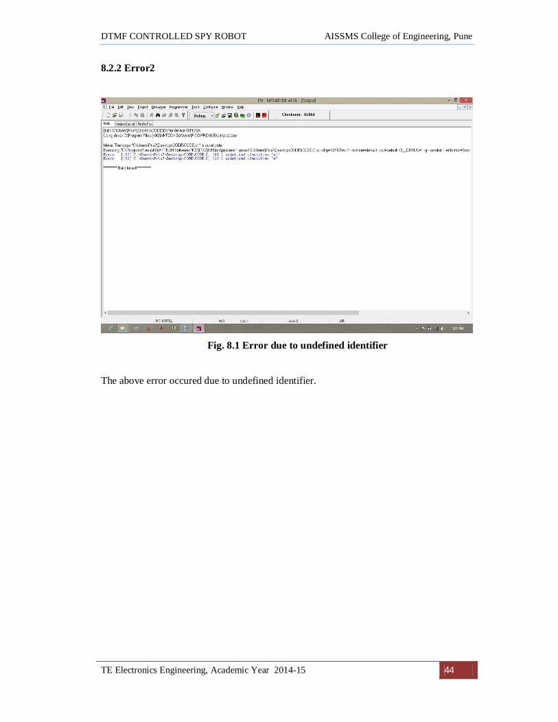
8.2.2 Error2
Fig. 8.1 Error due to undefined identifier
The above error occured due to undefined identifier.

DTMF CONTROLLED SPY ROBOT AISSMS College of Engineering, Pune
TE Electronics Engineering, Academic Year 2014-15 45
CHAPTER 9
ENCLOSURE DESIGN

DTMF CONTROLLED SPY ROBOT AISSMS College of Engineering, Pune
TE Electronics Engineering, Academic Year 2014-15 46
CHAPTER 9
ENCLOSURE DESIGN
9.1 DIMENSIONS OF THE PROJECT
1. Microcontroller board
2. Sensor PCB 3.Buzzer PCB

DTMF CONTROLLED SPY ROBOT AISSMS College of Engineering, Pune
TE Electronics Engineering, Academic Year 2014-15 47
4. Chassis 5. Wheels
6. Battery

DTMF CONTROLLED SPY ROBOT AISSMS College of Engineering, Pune
TE Electronics Engineering, Academic Year 2014-15 48
7. Robot

DTMF CONTROLLED SPY ROBOT AISSMS College of Engineering, Pune
TE Electronics Engineering, Academic Year 2014-15 49
CHAPTER 10
TESTING RESULTS

DTMF CONTROLLED SPY ROBOT AISSMS College of Engineering, Pune
TE Electronics Engineering, Academic Year 2014-15 50
CHAPTER 10
TESTING RESULTS
10.1 POWER SUPPLY
Fig. 10.1 Power Supply
a) We are using power supply of 5V and 12V.
b) 5V power supply required for PIC16F876A, L298, MT8870.
c) 12V power supply is required for Motors.
d) For 5V power supply 7805 regulator IC is used.
e) Capacitors are used for filtering purpose.
f) Output of power supply is given to the Vcc pin of every IC used in the circuit
diagram.

DTMF CONTROLLED SPY ROBOT AISSMS College of Engineering, Pune
TE Electronics Engineering, Academic Year 2014-15 51
10.2 TESTING OF POWER SUPPLY
Fig. 10.2 Power Supply Output
The above image shows the output of the power supply(5V) which is required for the
microcontroller, sensor, motor driver and buzzer to operate.
10.3 TESTING OF MOTORS
Fig. 10.3 Motor Driver Output
The above image shows the output of the motor driver which is required to drive the
motors.

DTMF CONTROLLED SPY ROBOT AISSMS College of Engineering, Pune
TE Electronics Engineering, Academic Year 2014-15 52
CHAPTER 11
CONCLUSION

DTMF CONTROLLED SPY ROBOT AISSMS College of Engineering, Pune
TE Electronics Engineering, Academic Year 2014-15 53
CHAPTER 11
CONCLUSION
From this investigation we should conclude that it is possible to produce an
alternative method to RF communication and reduces the amount of RF noise in the
environment. It should decrease the mystery of robots for the average user. This is a
wireless controlled robot hence the limitation of wired is completely overcome by using
latest technology of mobile phones. However, there are still lots of scopes to improve the
stability and ability of this system. The mobile phone that makes a call to mobile phone
stacked on the robot acts as a remote. Hence this project does not require the construction
of receiver and transmitter units. It is undoubtedly true that, this model can be a very
significant device in case of the information acquisition from the remote areas where
direct interference of human being is quite impossible hence it would be a very crucial
topic to do further research on it.

DTMF CONTROLLED SPY ROBOT AISSMS College of Engineering, Pune
TE Electronics Engineering, Academic Year 2014-15 54
FUTURESCOPE
1. IR Sensors
IR sensors can be used to automatically detect & avoid obstacles if the robot goes
beyond line of sight. This avoids damage to the vehicle if we are maneuvering it from
a distant place.
2. Password Protection
Project can be modified in order to password protect the robot so that it can be
operated only if correct password is entered. Either cell phone should be password
protected or necessary modification should be made in the assembly language code.
This introduces conditioned access & increases security to a great extent.
3. Alarm Phone Dialer
By replacing DTMF Decoder IC CM8870 by a 'DTMF Transceiver IC’ CM8880,
DTMF tones can be generated from the robot. So, a project called 'Alarm Phone
Dialer' can be built which will generate necessary alarms for something that is desired
to be monitored (usually by triggering a relay). For example, a high water alarm, low
temperature alarm, opening of back window, garage door, etc.
When the system is activated it will call a number of programmed numbers to let
the user know the alarm has been activated. This would be great to get alerts of alarm
conditions from home when user is at work.

DTMF CONTROLLED SPY ROBOT AISSMS College of Engineering, Pune
TE Electronics Engineering, Academic Year 2014-15 55
REFERENCES Books:
[1]Muhammad Ali Mazidi ,Rolin D. McKinlay , Danny Cause,llPIC Microcontrollers
And Embedded Systems, Pearson Education International.
[2]Kirk Zurell, C Programming for Embedded System.ARentice
Papers:
[1] Ashish Jadhav, Mahesh Kumbhar, and Meenakshi Pawar, Cell Phone Controlled
Ground Combat Vehicle, International Journal of Computer and Communication
Engineering, Vol. 1, No. 2, July 2012.
[2] Sabuj Das Gupta, Arman Riaz Ochi, Mohammad Sakib Hossain, Nahid Alam
Siddique, Design And Implementation of Mobile Operated Toy Car by DTMF,
International Journal of Scientific and Research Publications, Volume 3, Issue 1, January
2013.