“finite element modeling of radiofrequency cardiac and hepatic ablation” supan tungjitkusolmun...
TRANSCRIPT

““Finite Element Modeling of Finite Element Modeling of Radiofrequency Cardiac and Radiofrequency Cardiac and
Hepatic Ablation”Hepatic Ablation”
SUPAN TUNGJITKUSOLMUNSUPAN TUNGJITKUSOLMUNDept. Of Electrical and Computer Engineering
University of Wisconsin-Madison
Advisor: Professor John G. Webster

GoalGoal
Use Finite Element Modeling (FEM) to Improve the Efficacy of
Current RF Ablation Technologies and to Design New Electrodes

Introduction: RF ablation & FEMOverview: Finite element modeling process1. Effects of changes in myocardial properties2. Needle electrode creates deep lesions3. Uniform current density electrodes4. Bipolar phase-shifted multielectrode catheter5. Use FEM to predict lesion dimensions6. FEM of hepatic ablation
OutlineOutline

95% success rate in curing Supraventricular tachycardiasLow success rate for hepatic ablationDevelopment for VT (Large lesions)Development for AFIB (long thin lesions)
IntroductionIntroduction
What Is Ablation?Modes of operation
~500 kHz, < 50 WTemperature-controlledPower-controlled
Present Technology
Heating of cardiac tissue to cure rhythm disturbances and of liver tissue to cure cancer
What Is Ablation?Modes of operation

System for Cardiac AblationSystem for Cardiac Ablation
RF generator
Handle
Reference patchelectrode on the
dorsal side
Catheter body
Ablationelectrode
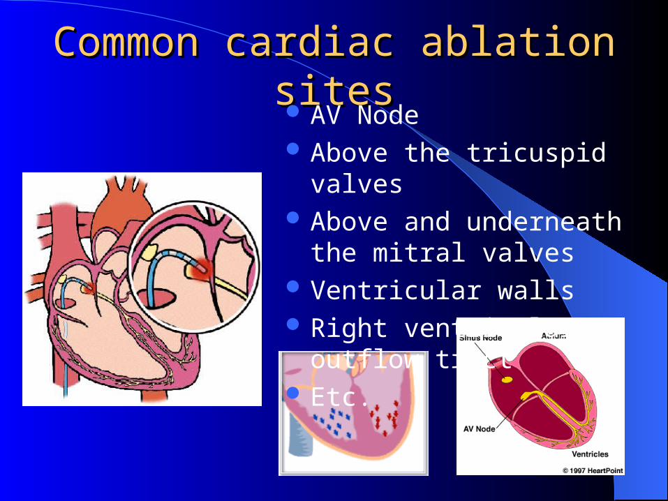
Common cardiac ablation sitesCommon cardiac ablation sites AV Node Above the tricuspid valves Above and underneath the
mitral valves Ventricular walls Right ventricular outflow tract Etc.

Tip ElectrodeTip Electrode RF generatorRF generator

Energies Involved in RF Energies Involved in RF Ablation ProcessAblation Process
Catheterbody
Myocardium
Blood
Convective coolingfrom blood
Electrode
Joule heat
Conduction tomyocardium
Conduction toelectrode
50 °C after1 s
50 °C after60 s
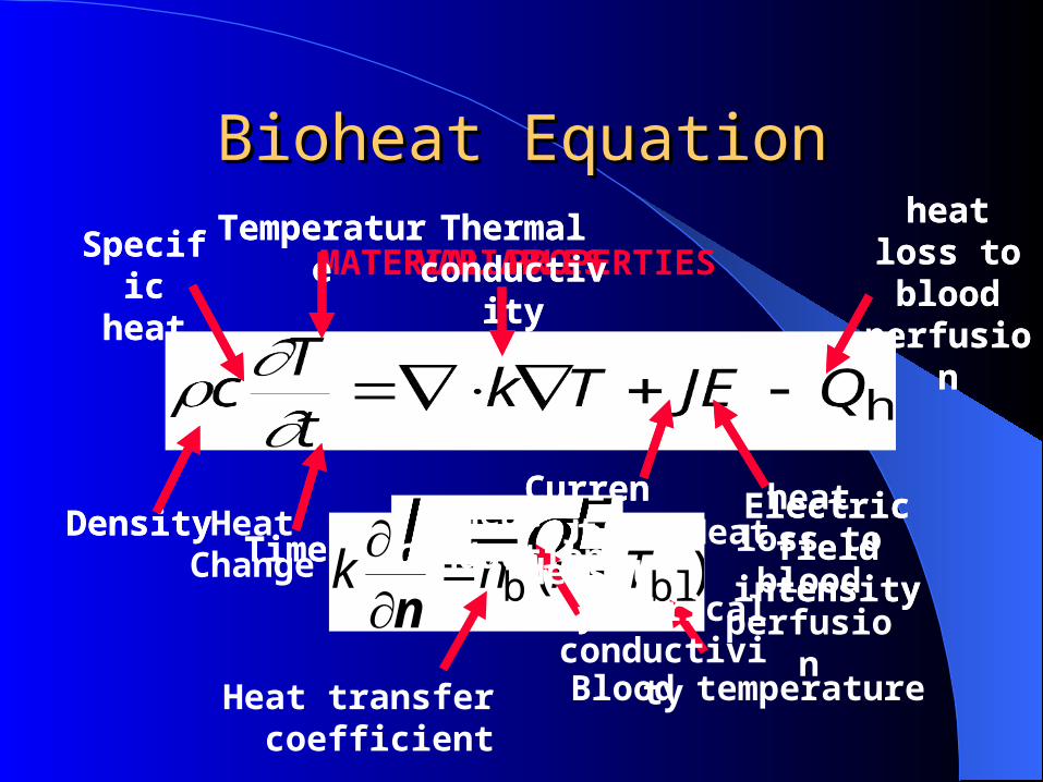
Bioheat EquationBioheat Equation
)( blb TThT
k n
Heat transfer coefficient Blood temperature
Density
Specific heat
Thermal conductivity
Time
Temperature
Current density
Electric field intensity
heat loss to blood
perfusionVARIABLES
Heat Change
MATERIAL PROPERTIES
Electrical conductivity
Density
Specific heat
Thermal conductivity
Time
Temperature
Current density
Electric field intensity
heat loss to blood
perfusion
heat loss to blood
perfusion
Heat Conduction
Joule Heat

Finite Element AnalysisFinite Element Analysis Divide the regions of interest into small “elements” Partial differential equations to algebraic equations 2-D (triangular elements, quadrilateral elements, etc.) 3-D (tetrahedral elements, hexahedral elements, etc.) Nonuniform mesh is allowed Software & Hardware
PATRAN 7.0 (MacNeal-Schwendler, Los Angeles ) ABAQUS 5.8 (Hibbitt, Karlsson & Sorensen, Inc.,
Farmington Hills, MI) HP C-180, 1152 MB of RAM, 34 GB Storage

Process for FEM GenerationProcess for FEM Generation
Geometry Material Properties Initial Conditions
Boundary Cond. Mesh Generation
Preprocessing (PATRAN 7.0)
Solution (ABAQUS/STANDARD 5.8)Duration Production Adjust Loads
Check for desired parameters
Postprocessing (ABAQUS/POST 5.8)Temperature Distribution Current Density
Determine Lesion Dimensions (from 50 C contour)
Convergence test (for optimal number of elements )

Modes of RF Energy ApplicationsModes of RF Energy Applications
Maintain the tip temperature at a preset valueAdjust voltage applied to the electrode
Temperature controlled ablationTemperature controlled ablation
Power controlled ablationPower controlled ablation
Maintain power delivered at a preset valueAdjust voltage applied to the electrode

1. Effects of changes in myocardial 1. Effects of changes in myocardial properties to lesion dimensions*properties to lesion dimensions*
*Tungjitkusolmun, S., Woo, E. J., Cao, H., Tsai, J.-Z., Vorperian, V. R.,and Webster, J. G.., Thermal-electrical finite element modeling for radio-frequency cardiac ablation: effects of changes in myocardialproperties, Med. Biol. Eng. Comput., accepted, 2000.
1.1 Electrical conductivity1.2 Thermal conductivity1.3 Specific heat (Density)
Material Material PropertiesProperties
For each case:For each case: Temperature independentTemperature dependentIncrease by 50%, or 100%Decrease by 50%

FEM resultsFEM results
Lesion growth over time (Red is 50 C or higher)

Temperature distribution after 60 sTemperature distribution after 60 s
Maximum temperature ~ 95 C
Highest temperature

Maximum changes in Lesion SizeMaximum changes in Lesion Size
Property Case % Volume Change
Electrical conductivity
50% 58.6
Thermal conductivity
+100% 60.7
Specific heat 50% +43.2
Power controlled

Property Case % Volume Change
Electrical conductivity
50% +12.9%
Thermal conductivity
50% 21.0%
Specific heat +100% 29.4%
Temperature controlled

ConclusionConclusion
Temperature dependent properties are important
Errors in Power-Controlled Mode are higher
Better measurement techniques are needed

2. Needle electrode design for VT*2. Needle electrode design for VT*
20
40 4010
1.3r
2
d
z
r
E. J. Woo, S. Tungjitkusolmun, H. Cao, J.-Z. Tsai, J. G. Webster, V. R. Vorperian, and J. A. Will, “A new catheter design using needle electrode for subendocardial RF ablation of ventricular muscles: finite element analysis and in-vitro experiments,” IEEE Trans. Biomed. Eng., vol. 47, pp. 2331, 2000.

MethodsMethods
Both FEM & in vitro experimentsVary needle diametersVary insertion depthsVary RF ablation durationChange temperature settingsCompare lesion dimensions

FEM ResultsFEM Results
Insertion depth (mm) Lesion width (mm) Lesion depth (mm)2.0 3.24 2.804.0 4.52 4.906.0 5.30 6.908.0 5.60 9.10
Needle Diameter (insertion = 8 mm)
Insertion Depth (diameter = 0.5 mm)
Diameter of needle (mm) Lesion width (mm) Lesion depth (mm)
0.5 5.60 9.1
0.6 6.06 9.1
0.7 6.24 9.1
0.8 6.50 9.1
0.9 6.77 9.2
1.0 7.04 9.3

ConclusionConclusion
Lesion depths are 1mm deeper than the insertion depth
Lesion width increases with increasing diameter and duration
Confirmed by in vitro experimentsGood contact

Needle electrode designsNeedle electrode designs

3. Uniform current density electrodes*3. Uniform current density electrodes*r
z
s
L 1
Insulator
1.3 mmd
Electrode
(a)
l
L 2
Electrode
(b)
z
1.3 mm
Insulatord
rCoating
*Tungjitkusolmun, S., Woo, E. J., Cao, H., Tsai, J.-Z., Vorperian, V. R., and Webster, J. G., Finite element analyses of uniform current density electrodes for radio-frequency cardiac ablation, IEEE Trans. Biomed. Eng., 47, pp. 32-40, January 2000.
“hot spot” at the edge of the conventional electrode
Uniform current density electrode by– Recession depth– contour on the surface
of the electrode (is the parameter for the shape function).
– Filled with coating material

FEM resultsFEM results
BloodCardiac tissue
Hot spot
+3.70E+01+4.12E+01+4.54E+01+4.96E+01+5.38E+01+5.80E+01+6.23E+01+6.65E+01+7.07E+01+7.49E+01+7.91E+01+8.33E+01+8.75E+01
TEMP VALUE
Hot spot at the edge of the metal electrode

Current densities at the edge Current densities at the edge of the tip electrodeof the tip electrode
0 0.1 0.2 0.3 0.4 0.5 0.6 0.7 0.8 0.9 12
3
4
5
6
7
8
9
10x 10
-3 Current density distribution
Distance (mm)
Cu
rre
nt
den
sity
(A
/mm
2 )
Flat
= 20
= 1 = 5
= 2
is the shape function

Cylindrical electrodesCylindrical electrodes
Changing conductivities Changing the curvatures (S/m) is for the shape function)

Current density distributionsCurrent density distributions
Cardiac tissue
Catheter body
Electrode
Highest currentdensity
+0.00E+00
+2.50E 01
+5.00E 01
+7.50E 01
+1.00E+00
ECDM VALUE
C SCALE = 144.
Flat
Catheter body
Cardiac tissue
Coating
Uniform currentdensity
+0.00E + 00
+2.50E 01
+5.00E 01
+7.50E 01
+1.00E + 00
C SCALE = 582.
ECDM VALUE
Recessed

4. Bipolar phase-shifted 4. Bipolar phase-shifted multielectrode catheter ablation*multielectrode catheter ablation*
*S. Tungjitkusolmun, H. Cao, D. Haemmerich, J.-Z. Tsai, Y. B. Choy, V. R. Vorperian, and J. G. Webster, “Modeling bipolar phase-shifted multielectrode catheter ablation,” in preparation, IEEE Trans. Biomed. Eng., 2000
Te
Tm

MethodMethod
A. 3-D Unipolar Multielectrode Catheter (MEC)B. Optimal phase-shifted for a system with fixed
myocardial properties
Optimal phase-shiftOptimal phase-shift: Te / Tm = 1C. Effects of changes in myocardial properties on
the optimal phase-shiftD. Optimal phase-shift for MEC with 3 mm
spacing

FEM resultsFEM results
Phase = 0Phase = 26.5Phase = 45

Phase vs. Phase vs. TTee//TTmm
Effect of electrical conductivity
00.20.40.60.8
11.21.41.61.8
0 10 20 30 40 50Phase (°)
Te
/Tm
control
low
high23.5° (high)
26.5° (control)
29.5° (low)
Changes in electrical conductivity

Changes in thermal conductivityChanges in thermal conductivity
Effect of thermal conductivity
00.20.40.60.8
11.21.41.61.8
2
0 10 20 30 40 50Phase (°)
Te
/Tm
control
low
high
26.5°

Electrode spacing (2mm vs. 3mm) Electrode spacing (2mm vs. 3mm)
Effect of inter-electrode distance
00.20.40.60.8
11.21.41.61.8
0 10 20 30 40 50Phase (°)
Te
/Tm 2 mm
3 mm
30.5° (3 mm)
26.5° (2 mm)

Simplified Control systemSimplified Control system

5. FEM predicts lesion size*5. FEM predicts lesion size*Ablation over the mitral valve annulusAblation underneath the mitral valve leaflets
*S. Tungjitkusolmun, V. R. Vorperian, N. C. Bhavaraju, H. Cao, J.-Z. Tsai, and J. G. Webster, “Guidelines for predicting lesion size at common endocardial locations during radio-frequency ablation,” submitted to IEEE.Trans. Biomed. Eng., 1999.

Physical conditionsPhysical conditions
Location Blood velocity (cm/s)
hb at bloodmyocardium
interface [(W/(m2K)]
hbe at bloodelectrode
interface [W/(m2K)]
Position 1
11.0 1417 4191
Position 2
2.75 44 2197
Position Contact Blood flow
1. Above the mitral valve 1.3 mm embedded High
2. Underneath the mitral valve 3.0 mm embedded Low
W
D
1.3 mm
Lesion
MyocardiumBlood
D
W
3 mm
Lesion
Blood
Myocardium
(a) (b)

Temperature Controlled RFTemperature Controlled RF
Lesion volume vs. time

Power controlled RFPower controlled RF
Lesion volume vs. time

6. FEM for Hepatic Ablation*6. FEM for Hepatic Ablation*
*S. Tungjitkusolmun, S. T. Staelin, D. Haemmerich, J.-Z. Tsai, H. Cao, V. R. Vorperian, F. T. Lee, D. M. Mahvi, and J. G. Webster, “Three-dimensional finite element analyses for radio-frequency hepatic tumor ablation,” submitted to IEEE. Trans. Biomed.Eng., 2000.
Hepatic Ablation: Use RF probe to destroy tumor cancer, or cirrhosis
Minimally invasive Present: -High recurrence rate
-Small lesions

ModelsModels
4-tine RF ProbeGeometry for FEM, 352,353 tetrahedral elements

Effect of Blood Vessel LocationEffect of Blood Vessel Location
No Blood Vessel Blood Vessel at 1 mm

Blood vessel at 5 mmBlood vessel at 5 mm

Bifurcated blood vesselBifurcated blood vessel
+37.0
+41.1
+45.2
+49.2
+53.3+57.4+61.5
+65.5+69.6
+73.7
+77.8
+81.9
+85.9
+90.0
TEMP VALUE
Blood vessel
Liver
Probe
ABHot spot

SummarySummary
1. Outline a process for FEM creation for RF ablation
2. Show that needle electrode catheter design can create deep lesions by FEM & in vitro studies
3. Uniform current density electrodes reduce “hot spots”
4. Bipolar phase-shifted multielectrode catheter can create long and contiguous lesions
5. We can use FEM to predict lesion formations6. Apply FEM for RF ablation to hepatic ablation

Bipolar Hepatic AblationBipolar Hepatic Ablation
Bipolar Unipolar