fire alarm and control system for fwblaffs acs-1 · typical arrangement of alarm and control system...
TRANSCRIPT

Voyage Data RecorderGeneral Alarm
weitere Bereiche entsprechendfurther sections accordingly
FeuermeldezentraleFire Detection PanelACS01.100
FernauslösegerätRemote ReleasePanelACS01.209
CAN-Bus
SchiffsüberwachungsanlageShip's Control System
Modulgehäusemit PumpenstarterModule Cabinetwith Pump StarterMC06.30x orMC06.40x
Pumpe 3~Pump440V 3~
50/60 Hz
Bereich 1Section 1
CAN-Bus FD FD
FDHandauslösung RP-01Manual Release RP-01
AlarmgeberAlarm Device
FeuermelderFire Detector
Anordnungsbeispiel Löschanlagensteuerung ACS-1Typical Arrangement of Alarm and Control System ACS-1
FD FD
Bereich 2Section 2
BereichsventilSection Valve
DüseNozzle
MENU
FIRE ALARM AND CONTROL SYSTEM ACS-1
FAULT
TEST
DISABLED
FIRE
POWER
SILENCE
DISCHARGE
ACK
Normal Operation
LOCAL APPLICATION FIRE FIGHTING RELEASE PANEL
ACKSILENCELamp Test
FIRE
FIRE
DISCHARGE
ST ART / ST OP
Pump PressurePower Common System Fault
1 Name of Section 1
2 Name of Section 2
4 Name of Section 4
3 Name of Section 3
5 Name of Section 5
6 Name of Section 6
7 Name of Section 7
8 Name of Section 8
9 Name of Section 9
Discharge Automati c OffPump N ot Rea dyDischarge Fai l ure
Po w erSu pp ly
Pum pswi tch
of f / a u t o / o n
Pu mpRun nin g
Pu mpno t rea d y
230V ~50/60 Hz
Fire Alarm and Control System for FWBLAFFSFixed Water Based Local Application Fire Fighting System according IMO MSC/Circ. 913
acs_prospekt_fwblaffs.tcd 06.08.2007
safetec Brandes und Niehoff GmbH Arenskule 7-9 21339 Lüneburg GermanyE-Mail: [email protected] Internet: www.safetec-online.com Tel.: +49-4131-76702-00
ACS-1
MENU
FIRE ALARM AND CONTROL SYSTEM ACS-1
FAULT
TEST
DISABLED
FIRE
POWER
SILENCE
DISCHARGE
ACK
Normal Operation
FeuermeldezentraleFire Alarm PanelMaße (Dimensions):240 x 144 x 50mm
Beschreibung Das Alarm and Control System ACS-1 ist ein flexibles Steuerungssystem für Feuerlöschanlagen mit folgenden Konfigurationsmöglichkeiten: • Steuerungssystem für Löschanlagen mit oder ohne inte-
griertem Feuermeldesystem für automatische Auslösung. Externes Feuermeldesystem kann über optionale Schnittstelle im Anzeigegerät oder Fern-auslösegerät angeschlossen werden.
• Sprinkleralarmsystem • Feuermeldesystem Die sehr kompakten Abmessungen vereinfachen Platzierung und Montage der Geräte erheblich. Der Systembus (CAN) reduziert den erforderlichen Verkabelungsaufwand. Weitere technische Daten: • max. 32 Löschbereiche • Bereichsventilansteuerung für Magnetventile oder
Drehantriebe • weitere Geräte wie Strömungsschalter oder Hauptventil
können angeschlossen werden • überwachte Stromkreise (Kurzschluss, Drahtbruch) • Zulassungen: BV, DNV, GL, LR, RINA, RMRS (Russia)
DescriptionThe Alarm and Control System ACS-1 is a control system for fire extinguishing plants. Due to its flexibility it can be applied in different arrangements: • Control system for extinguishing systems with or witout
integrated fire detection system for automatic release. External Fire Detection System can be connected by optional interfaces in the display panel or remote release panel.
• Sprinkler alarm system • Fire detection system The very compact dimensions of the devices ease planning and mounting of the system. A system bus (CAN) reduces expense for cabling work between the devices. Additional technical data: • max. 32 sections • section valves can be solenoids or motor actuators • additional devices like flow switches and main valve
can be connected • monitored circuits (short circuit, open circuit) • approvals: BV, DNV, GL, LR, RINA, RMRS (Russia)
Rev.1
MENU
16.0
5.20
06A
usga
be:
Rev.Gepr.Bearb. 17.09.03
29.10.04 kbkb15.05.06
1:3Maßstab
kb
5
ACS01.100.01.tcdFeueralarmzentrale Pultmontage, System ACSFire Alarm Panel, Flush Monting
FIRE ALARM AND CONTROL SYSTEM ACS-1
FAULT
TEST
DISABLED
FIRE
POWER
SILENCE
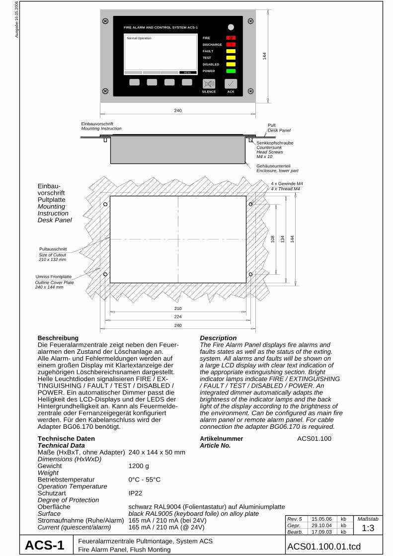
EinbauvorschriftMounting Instruction
PultDesk Panel
GehäuseunterteilEnclosure, lower part
240
144
SenkkopfschraubeCountersunk Head ScrewsM4 x 10
Beschreibung Description
werden. Für den Kabelanschluss wird der Adapter BG06.170 benötigt.
Die Feueralarmzentrale zeigt neben den Feuer-alarmen den Zustand der Löschanlage an. Alle Alarm- und Fehlermeldungen werden auf einem großen Display mit Klartextanzeige der zugehörigen Löschbereichsnamen dargestellt. Helle Leuchtdioden signalisieren FIRE / EX-TINGUISHING / FAULT / TEST / DISABLED / POWER. Ein automatischer Dimmer passt dieHelligkeit des LCD-Displays und der LEDS derHintergrundhelligkeit an. Kann als Feuermelde-zentrale oder Fernanzeigegerät konfiguriert
The Fire Alarm Panel displays fire alarms andfaults states as well as the status of the exting. system. All alarms and faults will be shown on a large LCD display with clear text indication of the appropriate extinguishing section. Bright indicator lamps indicate FIRE / EXTINGUISHING/ FAULT / TEST / DISABLED / POWER. An integrated dimmer automatically adapts the brightness of the indicator lamps and the backlight of the display according to the brightness ofthe environment. Can be configured as main fire alarm panel or remote alarm panel. For cable connection the adapter BG06.170 is required.
Technical Data
Gewicht
Betriebstemperatur
Schutzart
Weight
Operation Temperature
Degree of Protection
Technische Daten
Maße (HxBxT, ohne Adapter)Dimensions (HxWxD)
ArtikelnummerArticle No.
ACS01.100
OberflächeSurface
0°C - 55°C
1200 g
IP22
240 x 144 x 50 mm
schwarz RAL9004 (Folientastatur) auf Aluminiumplatteblack RAL9005 (keyboard foile) on alloy plate
108
224
4 x Gewinde M44 x Thread M4Einbau-
vorschriftPultplatteMountingInstructionDesk Panel
210
134
Pultausschnitt
Umriss Frontplatte
Size of Cutout210 x 132 mm
Outline Cover Plate240 x 144 mm
240
144
DISCHARGE
ACS-1
ACK
Stromaufnahme (Ruhe/Alarm)Current (quiescent/alarm)
165 mA / 210 mA (bei 24V)165 mA / 210 mA (@ 24V)
Normal Operation
Rev.Gepr.Bearb. 02.07.03
22.01.04 kbkb29.09.05
1:2Maßstab
HZ
2
Adaptermodul für FeueralarmzentraleAdapter Module for Fire Alarm Panel BG06.170.01.tcd
13.0
2.20
06A
usga
be:
11
21
11 11b ca a12 12 13 14 15 16 17
a 21b 21c a b22 22 23 24 25 26 27
b
41424344454647484950515253545556
61626364656667686970717273747576
ACS-1
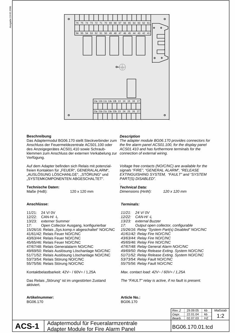
Beschreibung Description Das Adaptermodul BG06.170 stellt Steckverbinder zum Anschluss der Feuermeldezentrale ACS01.100 oder des Anzeigegerätes ACS01.410 sowie Schraub-klemmen zum Anschluss der externen Verkabelung zur Verfügung. Auf dem Adapter befinden sich Relais mit potenzial-freien Kontakten für „FEUER“, GENERALALARM“, „AUSLÖSUNG LÖSCHANLGE“, „STÖRUNG“ und „SYSTEMKOMPONENTEN ABGESCHALTET“.
The adapter module BG06.170 provides connectors for the fire alarm panel ACS01.100, for the display panel ACS01.410 and has furthermore terminals for the connection of external wiring. Voltage free contacts (NO/C/NC) are available for the signals “FIRE”, “GENERAL ALARM”, “RELEASE EXTINGUISHING SYSTEM, “FAULT” and “SYSTEM PART(S) DISABLED”. .
Technische Daten: Maße (HxB): 120 x 120 mm
Technical Data: Dimensions (HxW): 120 x 120 mm
Anschlüsse: 11/21: 24 V/ 0V 12/22: CAN-H/ -L 13/23: externer Summer 17: Open Collector Ausgang, konfigurierbar 15/26/16: Relais „Sys.komp.n abgeschaltet“ NO/C/NC 41/61/42: Relais Feuer NO/C/NC 43/63/44: Relais Feuer NO/C/NC 45/65/46: Relais Feuer NO/C/NC 47/67/48: Relais Generalalarm NO/C/NC 49/69/50: Relais Auslösung Löschanlage NO/C/NC 51/71/52: Relais Auslösung Löschanlage NO/C/NC 53/73/54: Relais Störung NO/C/NC 55/75/56: Relais Störung NO/C/NC Kontaktbelastbarkeit: 42V~ / 60V= / 1,25A Das Relais „Störung“ ist im ungestörten Zustand aktiviert.
Terminals: 11/21: 24 V/ 0V 12/22: CAN-H/ -L 13/23: external Buzzer 17: Output open collector, configurable 15/26/16: Relay “System Part(s) Disabled” NO/C/NC 41/61/42: Relay Fire NO/C/NC 43/63/44: Relay Fire NO/C/NC 45/65/46: Relay Fire NO/C/NC 47/67/48: Relay General Alarm NO/C/NC 49/69/50: Relay Release Exting. System NO/C/NC 51/71/52: Relay Release Exting. System NO/C/NC 53/73/54: Relay Fault NO/C/NC 55/75/56: Relay Fault NO/C/NC Max. contact load: 42V~ / 60V= / 1,25A The “FAULT” relay is active, if no fault is present.
Artikelnummer: BG06.170
Article No.: BG06.170
31.1
0.20
05A
usga
be:
Rev.Gepr.Bearb. 29.09.05
kb21.01.04
1:3Maßstab
kb
3
ACS01.209.01.tcdFernauslösegerät max. 9 Bereiche, System ACS-1Remote Release Panel, max. 9 Sections
Technische DatenTechnical DataGehäusemaße (HxBxT)
Abstand Befestigungsbohrungen
Gewicht
Schutzart
Betriebstemperatur
Stromaufnahme (Ruhe/Alarm)
Gehäusefarbe
Oberfläche Bedienfeld
Dimensions Enclosure (HxWxD)
Distance Mounting Holes
Weight
Degree of Protection
Operation Temperature
Current (quiescent/alarm)
Colour of Enclosure
Surface of Operation Field
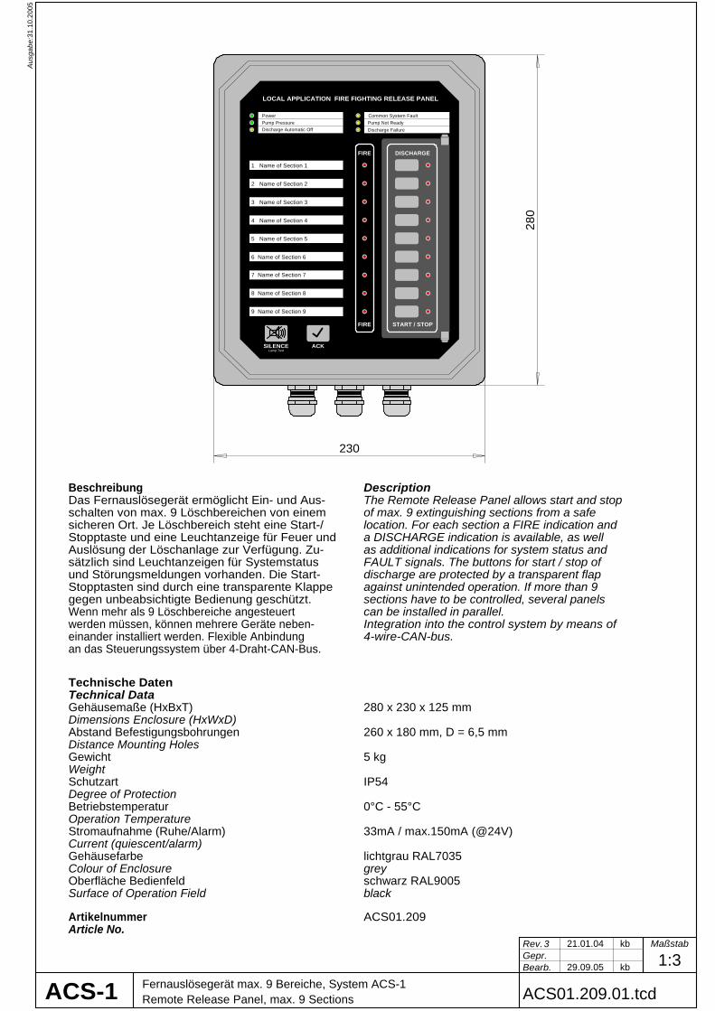
Beschreibung DescriptionDas Fernauslösegerät ermöglicht Ein- und Aus-schalten von max. 9 Löschbereichen von einemsicheren Ort. Je Löschbereich steht eine Start-/Stopptaste und eine Leuchtanzeige für Feuer und Auslösung der Löschanlage zur Verfügung. Zu-sätzlich sind Leuchtanzeigen für Systemstatus und Störungsmeldungen vorhanden. Die Start-Stopptasten sind durch eine transparente Klappegegen unbeabsichtigte Bedienung geschützt.Wenn mehr als 9 Löschbereiche angesteuertwerden müssen, können mehrere Geräte neben-einander installiert werden. Flexible Anbindung an das Steuerungssystem über 4-Draht-CAN-Bus.
The Remote Release Panel allows start and stopof max. 9 extinguishing sections from a safelocation. For each section a FIRE indication anda DISCHARGE indication is available, as well as additional indications for system status and FAULT signals. The buttons for start / stop ofdischarge are protected by a transparent flapagainst unintended operation. If more than 9sections have to be controlled, several panelscan be installed in parallel.Integration into the control system by means of 4-wire-CAN-bus.
280 x 230 x 125 mm
260 x 180 mm, D = 6,5 mm
5 kg
IP54
0°C - 55°C
33mA / max.150mA (@24V)
lichtgrau RAL7035
schwarz RAL9005
280
230
ArtikelnummerArticle No.
ACS01.209
grey
black
ACS-1
LOCAL APPLICATION FIRE FIGHTING RELEASE PANEL
ACKSILENCELamp Test
FIRE
FIRE
DISCHARGE
START / STOP
Pump PressurePower Common System Fault
1 Name of Section 1
2 Name of Section 2
4 Name of Section 4
3 Name of Section 3
5 Name of Section 5
6 Name of Section 6
7 Name of Section 7
8 Name of Section 8
9 Name of Section 9
Discharge Automatic OffPump Not ReadyDischarge Failure
11.0
2.20
08A
usga
be:
Rev.Gepr.Bearb. 07.08.03
30.06.05 kbkb05.02.08
1:7Maßstab
HZ
5
Modulgehäuse ACS01.308 für FWBLAFFSModule Cabinet ACS01.308 for FWBLAFFS ACS01.308.01.tcdACS-1
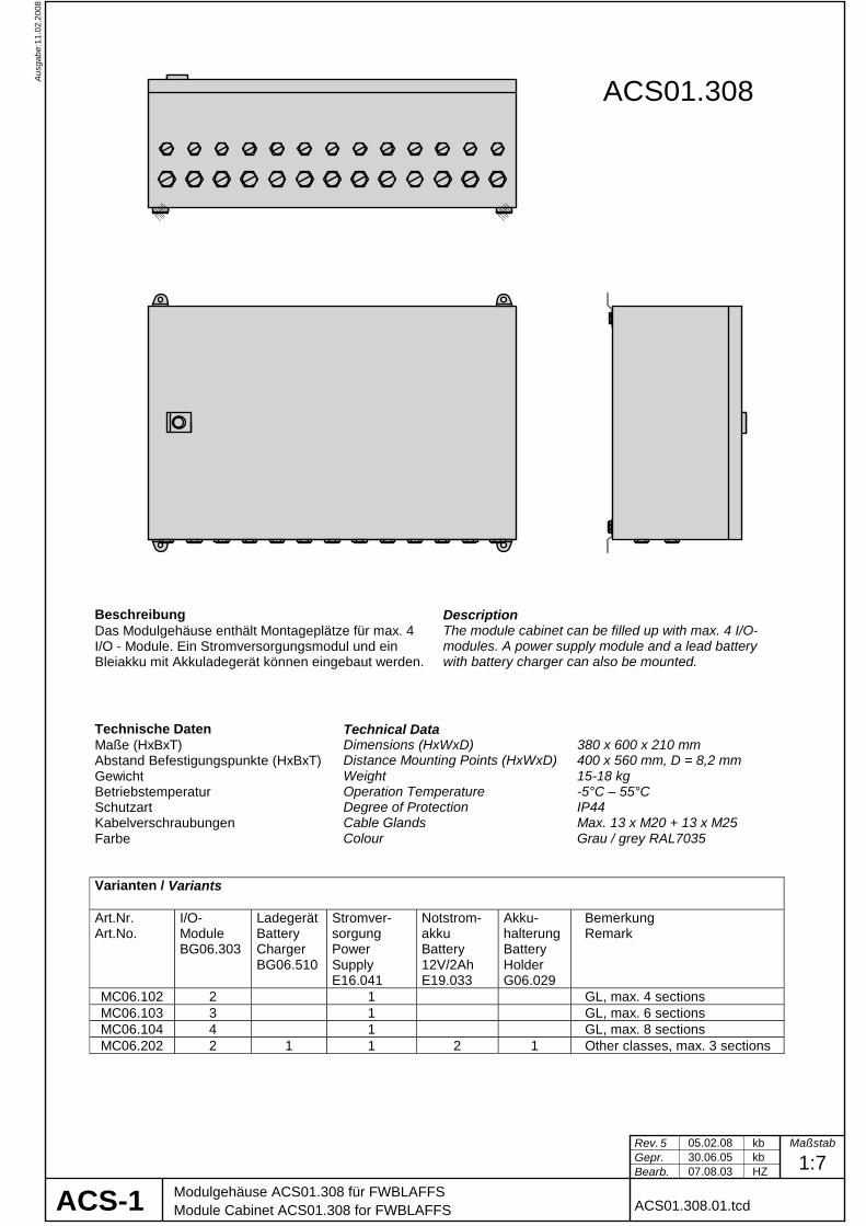
Beschreibung Das Modulgehäuse enthält Montageplätze für max. 4 I/O - Module. Ein Stromversorgungsmodul und ein Bleiakku mit Akkuladegerät können eingebaut werden.
Description The module cabinet can be filled up with max. 4 I/O-modules. A power supply module and a lead battery with battery charger can also be mounted.
Technische Daten Technical Data Maße (HxBxT) Dimensions (HxWxD) 380 x 600 x 210 mm Abstand Befestigungspunkte (HxBxT) Distance Mounting Points (HxWxD) 400 x 560 mm, D = 8,2 mm Gewicht Weight 15-18 kg Betriebstemperatur Operation Temperature -5°C – 55°C Schutzart Degree of Protection IP44 Kabelverschraubungen Cable Glands Max. 13 x M20 + 13 x M25 Farbe Colour Grau / grey RAL7035
Varianten / Variants Art.Nr. Art.No.
I/O-Module BG06.303
Ladegerät Battery Charger BG06.510
Stromver-sorgung Power Supply E16.041
Notstrom-akku Battery 12V/2Ah E19.033
Akku-halterung Battery Holder G06.029
Bemerkung Remark
MC06.102 2 1 GL, max. 4 sections MC06.103 3 1 GL, max. 6 sections MC06.104 4 1 GL, max. 8 sections MC06.202 2 1 1 2 1 Other classes, max. 3 sections
ACS01.308
11.0
2.20
08A
usga
be:
Rev.Gepr.Bearb. 15.06.04
30.06.05 kbkb05.02.08
1:7Maßstab
dt
2
Modulgehäuse mit integriertem Pumpenstarter, für FWBLAFFSModule Cabinet with integrated Pump Starter, for FWBLAFFS ACS01.308.02.tcdACS-1
PowerSupply
Pumpswitch
off/ auto/ on
PumpRunning
Pumpnot ready
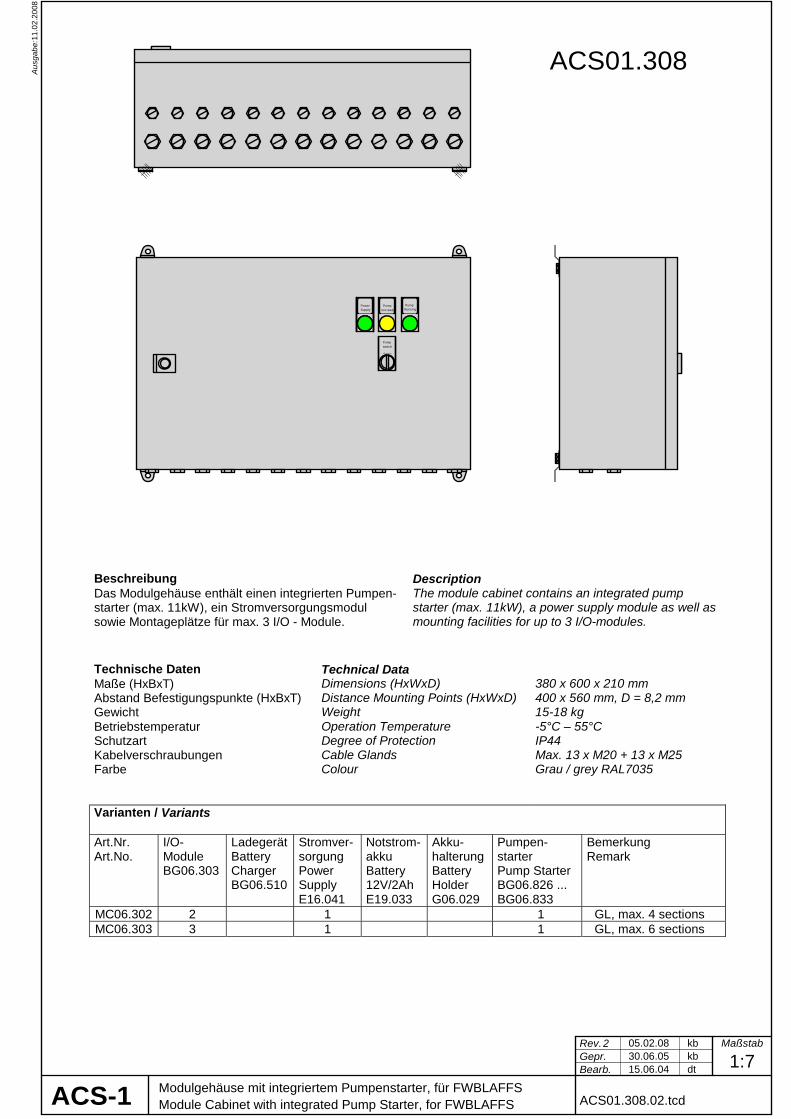
Beschreibung Das Modulgehäuse enthält einen integrierten Pumpen-starter (max. 11kW), ein Stromversorgungsmodul sowie Montageplätze für max. 3 I/O - Module.
Description The module cabinet contains an integrated pump starter (max. 11kW), a power supply module as well as mounting facilities for up to 3 I/O-modules.
Technische Daten Technical Data Maße (HxBxT) Dimensions (HxWxD) 380 x 600 x 210 mm Abstand Befestigungspunkte (HxBxT) Distance Mounting Points (HxWxD) 400 x 560 mm, D = 8,2 mm Gewicht Weight 15-18 kg Betriebstemperatur Operation Temperature -5°C – 55°C Schutzart Degree of Protection IP44 Kabelverschraubungen Cable Glands Max. 13 x M20 + 13 x M25 Farbe Colour Grau / grey RAL7035
Varianten / Variants Art.Nr. Art.No.
I/O-Module BG06.303
Ladegerät Battery Charger BG06.510
Stromver-sorgung Power Supply E16.041
Notstrom-akku Battery 12V/2Ah E19.033
Akku-halterung Battery Holder G06.029
Pumpen-starter Pump Starter BG06.826 ... BG06.833
Bemerkung Remark
MC06.302 2 1 1 GL, max. 4 sections MC06.303 3 1 1 GL, max. 6 sections
ACS01.308
11.0
2.20
08A
usga
be:
Rev.Gepr.Bearb. 05.10.04
30.06.05 kbkb05.02.08
1:7Maßstab
HZ
3
Modulgehäuse ACS01.312 für FWBLAFFSModule Cabinet ACS01.312 for FWBLAFFS ACS01.312.01.tcdACS-1
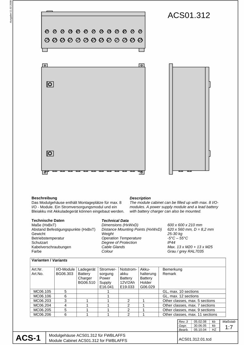
Beschreibung Das Modulgehäuse enthält Montageplätze für max. 8 I/O - Module. Ein Stromversorgungsmodul und ein Bleiakku mit Akkuladegerät können eingebaut werden.
Description The module cabinet can be filled up with max. 8 I/O-modules. A power supply module and a lead battery with battery charger can also be mounted.
Technische Daten Technical Data Maße (HxBxT) Dimensions (HxWxD) 600 x 600 x 210 mm Abstand Befestigungspunkte (HxBxT) Distance Mounting Points (HxWxD) 620 x 560 mm, D = 8,2 mm Gewicht Weight 25-30 kg Betriebstemperatur Operation Temperature -5°C – 55°C Schutzart Degree of Protection IP44 Kabelverschraubungen Cable Glands Max. 13 x M20 + 13 x M25 Farbe Colour Grau / grey RAL7035 Varianten / Variants Art.Nr. Art.No.
I/O-ModuleBG06.303
Ladegerät Battery Charger BG06.510
Stromver-sorgung Power Supply E16.041
Notstrom-akku Battery 12V/2Ah E19.033
Akku-halterung Battery Holder G06.029
Bemerkung Remark
MC06.105 5 1 GL, max. 10 sections MC06.106 6 1 GL, max. 12 sections MC06.203 3 1 1 2 1 Other classes, max. 5 sections MC06.204 4 1 1 2 1 Other classes, max. 7 sections MC06.205 5 1 1 2 1 Other classes, max. 9 sections MC06.206 6 1 1 2 1 Other classes, max. 11 sections
ACS01.312

11.0
2.20
08A
usga
be:
Rev.Gepr.Bearb. 21.03.05
30.06.05 kbkb30.06.05
1:7Maßstab
kb
1
Modulgehäuse mit integriertem PumpenstarterModule Cabinet with Integrated Pump Starter ACS01.312.02.tcdACS-1
PowerSupply
Pumpswitch
off/ auto/ on
PumpRunning
Pumpnot ready
Beschreibung Das Modulgehäuse enthält einen integrierten Pumpen-starter (max. 11kW), ein Stromversorgungsmodul sowie Montageplätze für max. 7 I/O - Module. Ein Not-stromakku mit Ladegerät kann eingebaut werden.
Description The module cabinet contains an integrated pump starter (max. 11kW), a power supply module as well as mounting facilities for up to 7 I/O-modules. A battery with charger can be added.
Technische Daten Technical Data Maße (HxBxT) Dimensions (HxWxD) 600 x 600 x 210 mm Abstand Befestigungspunkte (HxBxT) Distance Mounting Points (HxWxD) 620 x 560 mm, D = 8,2 mm Gewicht Weight 25-30 kg Betriebstemperatur Operation Temperature -5°C – 55°C Schutzart Degree of Protection IP44 Kabelverschraubungen Cable Glands Max. 13 x M20 + 13 x M25 Farbe Colour Grau / grey RAL7035 Varianten / Variants Art.Nr. Art.No.
I/O-Module BG06.303
Ladegerät Battery Charger BG06.510
Stromver-sorgung Power Supply E16.041
Notstrom-akku Battery 12V/2Ah E19.033
Akku-halterung Battery Holder G06.029
Pumpen-starter Pump Start. BG06.826 .. BG06.833
Bemerkung Remark
MC06.304 4 1 1 GL, max. 8 sections MC06.305 5 1 1 GL, max. 10 sections MC06.306 6 1 1 GL, max. 12 sections MC06.402 2 1 1 2 1 1 DNV, LR …, max. 3 sect. MC06.403 3 1 1 2 1 1 DNV, LR …, max. 5 sect. MC06.404 4 1 1 2 1 1 DNV, LR …, max. 7 sect. MC06.405 5 1 1 2 1 1 DNV, LR …, max. 9 sect.
ACS01.312

ACS-1
29.0
8.20
07A
usga
be:
Rev.Gepr.Bearb. 25.04.03
24.08.07 MPkb24.08.07
1:5Maßstab
HZ
6
Pumpenstarter Typ PST-LA8.. 1,1 - 7,5KWPump Starter Cabinet Type PST-LA8.. ACS01.830.01.tcd
Beschreibung Description
Technische DatenTechnical DataMaße (HxBxT)
Abstand Befestigungspunkte (HxBxT)
Gewicht
Betriebstemperatur
Schutzart
Kabelverschraubungen
Oberfläche und Farbe
Dimensions (HxWxD)
Weight
Operation Temperature
Degree of Protection
Cable Glands
Surface and Colour
Distance Mounting Points (HxWxD)
-5°C - 55°C
max. 3 x MS25
PowerSupply
Pumpswitch
off/ auto/ on
PumpRunning
Pumpnot ready
300 x200 x 155 mm
320 x 160 mm, D = 8,2 mm
Das Pumpenstartergehäuse enthält einen Pumpen-starter (von 1,1kW bis 7,5kW) mit Stromversorgungs-überwachung und Überlastüberwachung (optional: nur Überlastüberwachung ohne Abschaltung).
5,0 Kg
IP44
grau RAL7035
The pump starter cabinet contains a pump starter (1,1kW - 7,5kW) with power supply monitor and overload indication (optional:without overload shut down).
grey
ohne ÜberlastabschaltungVariants with Overload Shut Down
Leistung Typ enthältPower Type includes Type includes1,1 KW ACS01.806 PST-LA806 PSTM-LA806 ACS01.826 PST-LA826 PSTM-LA8261,5 KW ACS01.807 PST-LA807 PSTM-LA807 ACS01.827 PST-LA827 PSTM-LA8272,2 KW ACS01.808 PST-LA808 PSTM-LA808 ACS01.828 PST-LA828 PSTM-LA8283,0 KW ACS01.809 PST-LA809 PSTM-LA809 ACS01.829 PST-LA829 PSTM-LA8294,0 KW ACS01.810 PST-LA810 PSTM-LA810 ACS01.830 PST-LA830 PSTM-LA8305,5 KW ACS01.811 PST-LA811 PSTM-LA811 ACS01.831 PST-LA831 PSTM-LA8317,5 KW ACS01.812 PST-LA812 PSTM-LA812 ACS01.832 PST-LA832 PSTM-LA832
Varianten mit Überlastabschaltungwithout Overload Shut Down
Art.Nr. Art.Nr. Typ enthältArt.No. Art.No.

ACS-1
29.0
8.20
07A
usga
be:
Rev.Gepr.Bearb. 25.04.03
24.08.07 MPkb24.08.07
1:5Maßstab
HZ
6
Pumpenstarter Typ PST-LA8.. 11 - 18,5KWPump Starter Cabinet Type PST-LA8.. ACS01.832.01.tcd
PowerSupply
Pumpswitch
off/ auto/ on
PumpRunning
Pumpnot ready
Beschreibung Description
Technische DatenTechnical DataMaße (HxBxT) 300 x 380 x 210 mm
Abstand Befestigungspunkte (HxBxT)
Gewicht
Betriebstemperatur
Schutzart
Kabelverschraubungen
Oberfläche und Farbe
Dimensions (HxWxD)
Weight
Operation Temperature
Degree of Protection
Cable Glands
Surface and Colour
Distance Mounting Points (HxWxD)
-5°C - 55°C
max. 3 x MS25
grau RAL7035
320 x 340 mm, D = 8,2 mm
IP44
8,0 Kg
Das Pumpenstartergehäuse enthält einen Pumpen-starter (von 11kW bis 18,5kW) mit Stromversorgungs-überwachung und Überlastüberwachung (optional: nur Überlastüberwachung ohne Abschaltung).
The pump starter cabinet contains a pump starter (11kW - 18,5kW) with power supply monitor and overload indication (optional:without overload shut down).
grey
ohne ÜberlastabschaltungVariants with Overload Shut Down
Leistung Typ enthältPower Type includes Type includes11 KW ACS01.813 PST-LA813 PSTM-LA813 ACS01.833 PST-LA833 PSTM-LA83315 KW ACS01.814 PST-LA814 PSTM-LA814 ACS01.834 PST-LA834 PSTM-LA834
18,5 KW ACS01.815 PST-LA815 PSTM-LA815 ACS01.835 PST-LA835 PSTM-LA835
Varianten mit Überlastabschaltungwithout Overload Shut Down
Art.Nr. Art.Nr. Typ enthältArt.No. Art.No.

2k2
2k2
2k2
1 2 3 4 5 6 7 8 9
safetec
31.1
0.20
05A
usga
be:
Rev.Gepr.Bearb. 28.04.05
29.04.05 kb 1:4Maßstab
HZ
0
Muffenkugelhahn mit elektrischem DrehantriebThreaded Ball Valve with Electrical Motor Drive E10.300.01.tcd
J+J
AD
123 156
B
104
(B) MAN
(A) AUTO
C
M
S1 S2
S1: geschlossen, wenn Ventil geschlossen closed, when valve is shutS2: geschlossen, wenn Ventil geöffnet closed, when valve is open
externerAnschlussexternalConnection
Endschalter / Limit Switch
Kabel zwischen Ventilsteckern und Anschlussdose nicht dargestellt.Cables between valve plugs and connection box not shown.
externerAnschlussexternalConnection
Eigenschaften Der Muffen-Kugelhahn wird elektrisch über den angebauten Drehantrieb R-0-U betätigt. Mit einem Auto/Man-Umschalter kann der Antrieb auf Handbetrieb umgeschaltet werden. Der Motorstromkreis wird dabei abgeschaltet. Der Handhebel dient gleichzeitig zur optischen Stellungsanzeige. Inbetriebnahme Der Drehantrieb ist so anzuschließen, dass er rechts herum dreht. Die Drehrichtung bei Handbetrieb ist beliebig. Handbetrieb / Automatikbetrieb Schalten Sie den Auto/Man-Umschalter unter leichter Vor- und Rückdrehung des Handhebels auf die Position „MAN“. Danach kann die Armatur manuell verstellt werden. Zur Rückstellung auf den Automatikbetrieb schalten Sie den Auto/Man-Umschalter unter leichter Vor- und Rückdrehung des Handhebels wieder auf die Position „AUTO“. Dabei ist darauf zu achten, dass die Zähne der Getrieberäder wieder einrasten.
FeaturesThe threaded ball valve will be operated by the electrical motor drive R-0-U. The drive can be switched to manual operation by means of an Auto/Man selector. The motor circuit will be interrupted in this position. The valve handle serves also as visual position indicator. Commissioning The motor drive must be connected for clockwise rotation. The manual operation may be clockwise or anti-clockwise. Manual Operation and Automatic Operation For manual operation move the Auto/Man selector to position “MAN” and then rotate the manual override lever to the desired position. To switch back to “AUTO”, move the selector lever back to the “AUTO” position. Once in the “AUTO” position, gently try to rotate the manual override lever until the gears are engaged and it is not possible to further rotate the manual override lever under gentil pressure.
Technische Daten Ventilkörper Druckstufe Spannung max. Stromaufnahme Losbrechdrehmoment Arbeitsdrehmoment Einschaltdauer Arbeitszeit Schutzart Kabeleinführung Temperaturbereich
Technical Data Valve Body Pressure Nominal Voltage max. Current Starting torque Working torque Duty Rating Working Time Protection Cable Inlet Temperature Range
Messing, vernickelt / Brass, Nickel Plated CW617N UNI EN 12165 PN40 24V DC 1 A 25 Nm 20 Nm 35% ED 9s / 90° IP65 M20 -10 … +50 °C
Art.Nr. A B C D E10.301 1/2” DN15 195 176 67E10.302 3/4” DN20 200 180 76E10.303 1” DN25 215 190 90E10.304 1 ¼” DN32 223 194 102E10.305 1 ½” DN40 244 208 114E10.306 2” DN50 263 217 138

ACS-1
17.0
8.20
05A
usga
be:
Rev.Gepr.Bearb. 16.08.05 1:4
Maßstab
HZ
0
Alarmgeber Digitwin R/128/R, optisch/akustischAudible/Visible Alarm Digitwin R/128/R E18.041.01.tcd
Technische DatenTechnical DataBetriebsspannungsbereich
Betriebsstrom
Blitzintensität
Gewicht
Betriebstemperatur
Schutzart
Gehäuse
Operation Voltage
Operation Current
Flash Energy
Weight
Operation Temperature
Degree of Protection
Enclosure
10 ... 30V DC
ca. 200 mA
1,3J (24V)
640 g
-20°C ... +55°C
IP65
ABS / Polycarbonat
BeschreibungOptisch akustischer Alarmgeber mit 28 ver-schiedenen einstellbaren Schallmustern (Dip-Switch). Lautstärke kann per Potentiometereingestellt werden.
DescriptionVisible audible alarm with 28 different soundpatterns (Dip-switch). Volume control withpotentiometer.
Artikelnummer:Article No.:
E18.041
Digisound
101 113
5019
550
5
+ + -(1)
1K 3W
-(1)
-(2)
-(2)
+ + - -
Sounder
Flasher
47
ACS-1
17.0
8.20
05A
usga
be:
Rev.Gepr.Bearb. 16.08.05 1:4
Maßstab
HZ
0
Ton-Tabelle Digitwin R/128/RTone-Table Digitwin R/128/R E18.041.02.tcd
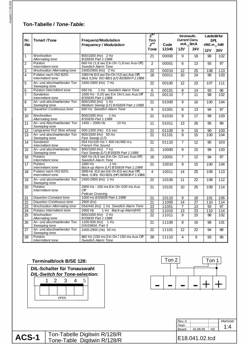
Ton-Tabelle / Tone-Table: Nr. /No
Tonart /Tone
Frequenz/Modulation Frequency / Modulation
2ter Ton 2nd
Tone
Code 12345
12V
24V
1 Wechselton Alternating tone
800/1000 (Hz) 2 Hz BS5839 Part 1:1988
21 00000 9 18 98 102
2 Pulston Intermittent tone
660 Hz (1,8 sec Ein On /1,8 sec Aus Off) Swedish Alarm Tone
2 00001 6 13 93 97
3 Wechselton Alternating tone 2400/2900 (Hz) 2 Hz 22 00010 12 25 108 113 4 Pulston nach ISO 8201
Intermittent tone 1000 Hz (0,5 sec Ein On / 0,5 sec Aus Off) Mod. 0,3Hz ISO 8201 (LF) BS5939 P.1:1988
18 00011 10 24 99 103
5 An- und abschwellender Ton Sweeping tone
2400-2900 (Hz) 7 Hz 22 00100 12 23 107 111
6 Pulston Intermittent tone 660 Hz 1 Hz Swedish Alarm Tone 6 00101 8 14 93 96 7 Sonderton
Intermittent tone 1000 Hz - 0,25 sec Ein On/1 sec Aus Off BS5839 Part 1:1988
21 00110 7 11 98 102
8 An- und abschwellender Ton Sweeping tone
800/1000 (Hz) 1 Hz Medium Sweep (LF) BS5839 Part 1:1988
21 01000 9 16 100 104
9 Dauerton Continuous tone 660 Hz Swedish Alarm Tone 9 01001 8 13 94 97
10 Wechselton Alternating tone
800/1000 (Hz) 1 Hz BS5839 Part 1:1988
21 01010 9 17 99 103
11 An- und Abschwellender Ton Sweeping tone
1400 – 2000 Hz 10 Hz 11 01011 13 26 95 99
12 Langsamer Ruf Slow whoop 500-1200 (Hz) 0,5 sec 21 01100 9 15 99 103 13 An- und abschwellender Ton
Sweeping tone 800/1000 (Hz) 50 Hz Fast Sweep (LF)
21 01101 9 15 100 104
14 Sonderton Intermittent tone
554 Hz/100 ms + 400 Hz/400 ms French Fire Sound
21 01110 7 12 95 100
15 An- und abschwellender Ton Sweeping tone
800/1000 (Hz) 7 Hz Fast Sweep (LF) BS5839 Part 1:1988
21 10000 9 15 99 103
16 Pulston Intermittent tone
660 Hz (6,5 sec Ein On /13 sec Aus Off) Swedish Alarm Tone
16 10001 7 12 94 97
17 Pulston Intermittent tone
1000 Hz 1 Hz Back-up Alarm (LF) BS5839 Part 1:1988
21 10010 9 15 100 104
18 Pulston nach ISO 8201 Intermittent tone
2900 Hz (0,5 sec Ein On /0,5 sec Aus Off) Mod.: 0,3Hz ISO 8201 (HF) BS5839 P.1:1988
4 10011 14 25 109 113
19 An- und abschwellender Ton Sweeping tone
2400-2900 (Hz) 1 Hz 22 10100 11 22 108 112
20 Pulston Intermittent tone
2900 Hz - 150 ms Ein On /100 ms Aus Off Pelican Crossing
21 10101 10 25 109 114
21 Dauerton Constant tone 1000 Hz BS5839 Part 1:1988 21 10110 9 18 101 105 22 Dauerton Continuous tone 2900 (Hz) 21 11000 14 27 110 114 23 Wechselton Alternating tone 554/440 (Hz) 1 Hz Swedish Alarm Tone 23 11001 7 13 93 97 24 Pulston Intermittent tone 2900 Hz 1 Hz Back-up Alarm(HF) 22 11010 13 23 110 114 25 Wechselton
Alternating tone 800/1000 (Hz) 2 Hz BS5839 Part 1:1988
22 11011 9 15 98 102
26 An- und abschwellender Ton Sweeping tone
1200-500 (Hz) 1 Hz DIN33404, Part 3
21 11100 8 16 98 101
27 An- und abschwellender Ton Sweeping tone
2400-2900 (Hz) 50 Hz 22 11101 12 22 94 98
28 Pulston Intermittent tone
660 Hz (150 ms Ein On / 150 ms Aus Off Swedish Alarm Tone
28 11110 4 9 93 96
Terminalblock B/SE 128:
Ton 1Ton 2
- - - - + +
Stromaufn. Current Cons. mA ±3mA
Lautstärke SPL
dB/1 m ± 3dB
24V12V
DIL-Schalter für Tonauswahl DIL-Switch for Tone-selection:
1 2 3 4 5
OPEN
ACS-1
17.0
8.20
05A
usga
be:
Rev.Gepr.Bearb. 16.08.05 1:4
Maßstab
HZ
0
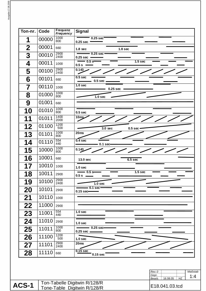
Ton-Tabelle Digitwin R/128/RTone-Table Digitwin R/128/R E18.041.03.tcd
Ton-nr. Code Frequenz Frequency /H
Signal
1 00000 1000 800
0.25 sec 0.25 sec
2 00001 660 1.8 sec 1.8 sec
3 00010 2900 2400
0.25 sec 0.25 sec
4 00011 1000 0.5 s 1.5 sec 0.5 s
5 00100 2900 2400
0.143
6 00101 660 0.5 sec 0.5 sec
7 00110 1000 1.0 sec 0.25 sec
8 01000 1000 800
1.0 sec
9 01001 660
10 01010 1000 800
0.5 sec
11 01011 1400 2000
10ms
12 01100 1200 500
3.0 sec 0.5 sec
13 01101 1000 800
20ms
14 01110 554 440
0.4 sec 0.1 sec
15 10000 1000 800
0.143
16 10001 660 13.0 sec 6.5 sec
17 10010 1000 1.0 sec
18 10011 2900 0.5 s 1.5 sec 0.5 s
19 10100 2900 2400
1.0 sec
20 10101 2900 0.1 sec 0.15 sec
21 10110 1000
22 11000 2900
23 11001 554 440
1.0 sec
24 11010 2900 1.0 sec
25 11011 1000 800
0.25 sec 0.25 sec
26 11100 1200 500
1.0 sec
27 11101 2900 2400
20ms
28 11110 660 0.15 sec 0.15 sec

20.1
0.20
05A
usga
be:
Rev.Gepr.Bearb. 02.03.05 1:3
Maßstab
kb
0
Optischer Rauchmelder ORBISOptical Smoke Detector ORBIS E20.200.01.tcdACS-1
129
110
146
100
82
mit Standardsockelwith standard base
mit Feuchtraumsockelwith water protected base
3 x PG16
2 x D=4
Beschreibung Description Fotoelektrischer Rauchmelder nach dem Streulichtprinzip. Die Anordnung der Optik enthält eine Infrarot-Leuchtdiode mit Prisma und im Winkel von 90° eine Fotodiode mit einem großen Sichtwinkel. Der Mikroprozessor des Rauchmelders benutzt spezielle Algorithmen zur Auswertung der Sensorwerte. LED-Funktionen während der Startphase Während der Startphase (4 Minuten nach Reset) blitzt die LED jede Sekunde einmal rot auf und zeigt damit an, dass der Rauchmelder in der richtigen Polarität angeschlossen ist. Wenn die LED während der Startphase einmal pro Sekunde gelb aufblitzt, wurde die Obergrenze der auto-matischen Verschmutzungskompensation erreicht. Der Rauchmelder sollte demnächst ausgewechselt werden. Wenn die LED nach der Startphase einmal alle 4 Sekunden gelb aufblitzt, zeigt sie an, dass der Rauchmelder nicht ordnungsgemäß arbeitet. Weitere Informationen siehe separates Datenblatt.
Photo-electric detection of light scattered by smoke particles over a wide range of angles. The optical arrangement comprises an infrared emitter with a prism and a photo-diode at 90° to the light beam with a wide field of view. The detector's microprocessor uses algorithms to process the sensor readings. LED functions during start up During start up (4 minutes after reset) the detector LED flashes red once per second to confirm that the detector is wired in the correct polarity. If during start up the detector LED flashes yellow once per second, the drift compensation limit has been reached. The smoke detector should be exchanged soon. If after start up the detector LED flashes yellow once every 4 seconds, the sensor is not operating properly.For more see separate data sheet.
Technische Daten: Maße (DxH): 100mm x 42mm, 75g mit Sockel: 100mm x 50mm, 135g Betriebsspannung: 8,5V-33V DC Ruhestrom (24V): 65µA Betriebstemperatur: -40°C-+70°C IP-Schutzart: 23D Material: Melder und Sockel Spritz- guss aus weißem Polycarb.
Technical Data: Dimensions (DxH): 100mm x 42mm, 75g With socket: 100mm x 50mm, 135g Supply Voltage: 8,5V-33V DC Quiescent Current (24V): 65µA Operation Temperature: -40°C-+70°C IP-Rating: 23D Material: Detector and base moulded in white polycarbonate
Artikelnummern: E20.200: Rauchmelder E20.290: Standardsockel E20.193: Feuchtraumsockel
Article Nos: E20.200: Detector Head E20.290: Standard Socket E20.193: Socket, water protected
14.0
5.20
07A
usga
be:
Rev.Gepr.Bearb. 14.05.07 1:3
Maßstab
kb
0
Multisensor-Rauchmelder ORBISMultisensor Smoke Detector ORBIS E20.201.01.tcdACS-1
129
110
146
100
mit Standardsockelwith standard base
mit Feuchtraumsockelwith water protected base
3 x PG16
2 x D=4
85
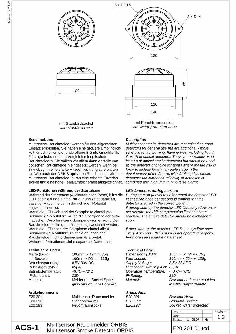
Beschreibung Description Multisensor Rauchmelder werden für den allgemeinen Einsatz empfohlen. Sie haben eine größere Empfindlich-keit für schnell entstehende offene Brände einschließlich Flüssigkeitsbränden im Vergleich mit optischen Rauchmeldern. Sie sollten vor allem dann anstelle von optischen Rauchmeldern eingesetzt werden, wenn bei Brandbeginn eine starke Hitzeentwicklung zu erwarten ist. Wie auch der ORBIS optischen Rauchmelder wird der Multisensor Rauchmelder durch eine erhöhte Zuverläs-sigkeit und eine hohe Fehlalarmsicherheit ausgezeichnet. LED-Funktionen während der Startphase Während der Startphase (4 Minuten nach Reset) blitzt die LED jede Sekunde einmal rot auf und zeigt damit an, dass der Rauchmelder in der richtigen Polarität angeschlossen ist. Wenn die LED während der Startphase einmal pro Sekunde gelb aufblitzt, wurde die Obergrenze der auto-matischen Verschmutzungskompensation erreicht. Der Rauchmelder sollte demnächst ausgewechselt werden. Wenn die LED nach der Startphase einmal alle 4 Sekunden gelb aufblitzt, zeigt sie an, dass der Rauchmelder nicht ordnungsgemäß arbeitet. Weitere Informationen siehe separates Datenblatt.
Multisensor smoke detectors are recognised as good detectors for general use but are additionally more sensitive to fast burning, flaming fires–including liquid fires–than optical detectors. They can be readily used instead of optical smoke detectors but should be used as the detector of choice for areas where the fire risk is likely to include heat at an early stage in the development of the fire. As with Orbis optical smoke detectors the increased reliability of detection is combined with high immunity to false alarms. LED functions during start up During start up (4 minutes after reset) the detector LED flashes red once per second to confirm that the detector is wired in the correct polarity. If during start up the detector LED flashes yellow once per second, the drift compensation limit has been reached. The smoke detector should be exchanged soon. If after start up the detector LED flashes yellow once every 4 seconds, the sensor is not operating properly. For more see separate data sheet.
Technische Daten: Maße (DxH): 100mm x 42mm, 75g mit Sockel: 100mm x 50mm, 135g Betriebsspannung: 8,5V-33V DC Ruhestrom (24V): 65µA Betriebstemperatur: -40°C-+70°C IP-Schutzart: 23D Material: Melder und Sockel Spritz- guss aus weißem Polycarb.
Technical Data: Dimensions (DxH): 100mm x 42mm, 75g With socket: 100mm x 50mm, 135g Supply Voltage: 8,5V-33V DC Quiescent Current (24V): 65µA Operation Temperature: -40°C-+70°C IP-Rating: 23D Material: Detector and base moulded in white polycarbonate
Artikelnummern: E20.201: Multisensor-Rauchmelder E20.290: Standardsockel E20.193: Feuchtraumsockel
Article Nos: E20.201: Detector Head E20.290: Standard Socket E20.193: Socket, water protected

20.1
0.20
05A
usga
be:
Rev.Gepr.Bearb. 01.09.05 1:3
Maßstab
HZ
0
Thermomelder ORBISHeat Detector ORBIS E20.220.01.tcdACS-1
129
110
146
100
mit Standardsockelwith standard base
mit Feuchtraumsockelwith water protected base
3 x PG16
2 x D=4
BR
85
BR
Beschreibung Description Orbis-Thermomelder können in Bereichen mit hoher Staub- oder Rauchkonzentration eingesetzt werden. Das Schutzgehäuse der Thermomelder erlaubt eine freie Luft-zirkulation zu dem Thermistor, der alle 2 Sekunden die Lufttemperatur misst. Wenn die voreingestellten Werte überschritten werden, wird der Alarmstatus ausgelöst. Die verfügbaren sechs Varianten erlauben eine Anpas-sung an unterschiedliche Umgebungsbedingungen. Ther-momaximalmelder („static“) sprechen nur nach Erreichen einer bestimmten Temperaturschwelle an. Thermodif-ferentialmelder („rate-of-rise“) haben auch eine maximale Ansprechschwelle, lösen aber auch bei Überschreiten einer vorgegebenen Anstiegsgeschwindigkeit aus. LED-Funktionen während der Startphase Während der Startphase (4 Minuten nach Reset) blitzt die LED jede Sekunde einmal rot auf und zeigt damit an, dass der Rauchmelder in der richtigen Polarität ange-schlossen ist. Weitere Infos siehe separates Datenblatt.
Orbis heat detectors are suitable in atmospheres with high dust content or where fumes may temporarily be concentrateds. The heat detectors have an open-web casing that allows air to flow freely across a thermistor which measures the air temperature every 2 seconds. The stored temperatures are then compared against pre-set values to determine whether an alarm level has been reached. There are six heat detectors to suit a wide variety of operating conditions. Static heat detectors respond only when a fixed temperature has been reached. Rate-of-rise detectors have a fixed upper limit too, but they also measure the rate of increase in temperature. LED functions during start up During start up (4 minutes after reset) the detector LED flashes red once per second to confirm that the detector is wired in the correct polarity. For more information see separate data sheet.
Technische Daten: Maße (DxH): 100mm x 42mm, 70g mit Sockel: 100mm x 50mm, 130g Betriebsspannung: 8,5V-33V DC Ruhestrom (24V): 65µA Betriebstemperatur: -40°C-+70°C IP-Schutzart: 23D Material: Melder und Sockel Spritz- guss aus weißem Polycarb.
Technical Data: Dimensions (DxH): 100mm x 42mm, 70g With socket: 100mm x 50mm, 130g Supply Voltage: 8,5V-33V DC Quiescent Current (24V): 65µA Operation Temperature: -40°C-+70°C IP-Rating: 23D Material: Detector and base moulded in white polycarbonate
Artikelnummern: E20.221: Thermodifferentialmelder Class A1R (57°C) E20.222: Thermomaximalmelder Class A2S (57°C) E20.223: Thermodifferentialmelder Class BR (75°C) E20.224: Thermomaximalmelder Class BS (75°C) E20.225: Thermodifferentialmelder Class CR (90°C) E20.226: Thermomaximalmelder Class CS (90°C) E20.290: Standardsockel E20.193: Feuchtraumsockel
Article Nos: E20.221: Thermodifferentialmelder Class A1R (57°C) E20.222: Thermomaximalmelder Class A2S (57°C) E20.223: Thermodifferentialmelder Class BR (75°C) E20.224: Thermomaximalmelder Class BS (75°C) E20.225: Thermodifferentialmelder Class CR (90°C) E20.226: Thermomaximalmelder Class CS (90°C) E20.290: Standard Socket E20.193: Socket, water protected

05.0
3.20
07A
usga
be:
Gepr.Bearb. 04.08.03
17.10.05 kb 1:3HZ
UV-Flammenmelder 800/24 VST-K-NT (A)UV-Flame-Detector E22.001.01.tcd
Technische DatenTechnical DataBetriebsspannungsbereich:Operation Voltage
GewichtWeightBetriebstemperaturOperation Temperature
AlarmschwelleSensitivity
Stromaufnahme betriebsbereitNormal Current ConsumptionStromaufnahme AlarmCurrent Consumption Alarm
SchutzartDegree of ProtectionKabelverschraubungenCable GlandsGehäuseEnclosure
Relay Contacts Alarm/FaultRelaiskontakte Alarm/Störung
Empfindlichkeit (nach EN54 Teil10):
Empfindlicher Bereich:Wavelength
19,2 - 28,8 V
-25°C - 70°C
ca. 0,8 kg
EN54-10 Klasse 1
ca. 26 mA
ca. 46 mA (24V)
PC-LEXAN 241R
30V DC, 1A
>25m (Brandempfindlichkeitsklasse 1)>25m (Sensitivity Class 1)
UV-C 200 nm - 280 nmMaximum: 210 nm +/- 10 nm
IP54
Sensitivity (acc. EN54 Part10):
aufsteckbare Blende zur Ver-kleinerung des Sichtwinkelspluggable tube for reductionof viewing angle
Achtung ! Important Notice
Rev. kb05.03.07 Maßstab6
UV-sources with high intensity like welding, special lamps, arcs and ionizating radiation (radioactivity, X-ray) can generate false alarms. Furthermore reflected UV-radiation of appropriate intensity willbe detected by the flame detector and can generatefalse alarms.The viewing angle of the flame detector can bereduced by means of tubes with different lengths,which can be plugged on the sensor lens. Threetubes with different lenghts will be supplied with theflame detector.
Stark UV-abstrahlende Quellen, wie z.B. Schweiß-flammen, Speziallampen, Lichtbogenlampen undionisierende Strahlung (Radioaktivität, Röntgen-strahlung), können zu Fehlalarmen führen. Auchreflektierte UV-Strahlung von entsprechender Inten-sität wird vom Flammenmelder erfasst und führt zurAlarmmeldung. Der Sichtwinkel des Flammen-melders kann durch verschieden lange aufsteck-bare Blendenröhrchen verringert werden. Drei ver-schieden lange Blendenröhrchen werden mit-geliefert.
ACS-1
Artikelnummern / Typ:
E22.001 800/24VST-K-NT Alarmwiderstand Alarm Resistor 2200 OhmE22.003 800/24VST-K-NT A Alarmwiderstand Alarm Resistor ~560 Ohm
120135
150
112130
147
ø 5 mm
Article Nos / Type:
188
200
Sichtwinkel: 90° mit Blende 29 mm45° mit Blende 47 mm30° mit Blende 65 mm
Viewing Angle:
ohne Blende: bis 180° mit abnehmender Empfindlichkeit

Rev.Gepr.Bearb. 09.10.07 1:2
Maßstab
kb
0
RP01.001.01.tcd
07.0
2.20
08A
usga
be:
Main Engine
Lokales Auslösegerät RP-01Local Release Box
START / STOP
ACS-1
LOCAL RELEASE BOXFIRE FIGHTING SYSTEM
I-0
1 21 2 22 3 23 4 24 5 25 6 26 7 27 8 28
D1 D2 D5 D3
S1 F1
R1SchaltbildCircuit Diagram
Supply Flame Detector
+ +- - + - + -
Loop 1 Loop 2 (incl.Push Button)
AlarmDevice(s)
Funktionsbeschreibung
• Das lokale Auslösegerät wird gut zugänglich in der Nähe des geschützten Bereiches installiert. Mit Hilfe des Drucktasters kann die Löschung gestartet oder abgebrochen werden.
• Der Drucktaster befindet sich in einer Vertiefung und ist dadurch gegen versehent-liche Betätigung geschützt.
• Das lokale Auslösegerät bietet Anschluss-möglichkeiten für die zum Löschbereich gehörigen Feuermelder und den optisch / akustischen Alarmgeber.
• Oberhalb des Tasters kann ein Schild mit der Bezeichnung des Löschbereichs eingefügt werden.
• Bei entsprechender Konfiguration des I/O- Moduls können maximal vier automatische Feuermelder zusammen mit dem Auslöse-taster an einer Meldelinie angeschlossen werden.
Description • The Local Release Box must be
mounted near to the protected space. By means of the push button the extinguishing system can be released and stopped.
• The push button is located in a deepening and thus protected against unintended operation.
• The Local Release Box offers terminals for the connection of the local fire detectors and the local visible/audible alarm device.
• A label with the name of the protected space can be inserted above the push button.
• With appropriate configuration of the I/O-module, max. four automatic fire detectors can be connected together with the manual push button to one detection line.
Technische Daten Maße (BxHxT) Abstand Befestigungsbohr. Durchm. Befestig.bohrungen Gewicht Betriebstemperatur Schutzart Kabelverschraubungen Gehäuse Frontfolie Artikelnummer
Technical Data Dimensions (WxHxD) Position Mounting Borings Diameter Mounting Borings Weight Operation Temperature Degree of Protection Cable Glands Enclosure Cover Foil Article No.
160 x 80 x 56 mm 148,3 x 50,2 mm 4,5 mm 0,35 kg 0°C – 55°C IP65 1 x M25, 2 x M20 Polycarbonat RAL3000 RP01.001