fire alarm detection and notification systems
TRANSCRIPT

WASHINGTON METROPOLITAN AREA TRANSIT AUTHORITY
REQUEST FOR PROPOSAL (RFP)/CONTRACT NO. FQ13032
FIRE ALARM DETECTION AND NOTIFICATION SYSTEMS
Task Order Contract
BOOK 3
Related WMATA Sections
DATE: MAY 20, 2013

RFP: FQ13032/WJG – FIRE ALARM DETECTION AND NOTIFICATION SYSTEMS
Book 3 Related WMATA Sections 1
Section Description 16732 Fire Alarm, Detection and Notification System 08331 Overhead Coiling Doors 08710 Finish Hardware 13905 Fire Protection, Suppression and Alarm 14200 Hydraulic Elevators 14240 Traction Elevators 14300 Heavy-Duty Escalator 16120 Wire, Cable and Busways 16130 Raceways, Boxes and Cabinets 16705 Communications Standard Specifications – Equipment and Material 16707 Communications Systems Quality Assurance & Testing 16710 Communications Grounding 16715 Communications Electrical Power Distribution 16733 Communications – Kiosk Systems 16821 Communications – Automatic Public Address Announcement System 16925 ATC – Data Transmission System (DTS)
1X0000 (03/03) 08331 - 1
SECTION 08331
OVERHEAD COILING DOORS
PART 1 - GENERAL
1.01 DESCRIPTION:
A. This section specifies providing overhead coiling doors.
B. Related Work Specified Elsewhere:1. Miscellaneous Metal: Section 05500.2. Finish Hardware: Section 08710.3. Field Painting: Section 09920.
1.02 DEFINITIONS:
A. Operation Cycle: One complete cycle of a door begins with the door in the closed position.The door is then moved to the open position and back to the closed position.
1.03 PERFORMANCE REQUIREMENTS:
A. Structural Performance: Provide overhead coiling doors capable of withstanding the effectsof gravity loads and the following loads and stresses without evidencing permanentdeformation of door components:1. Wind Load: Uniform pressure (velocity pressure) of 20 lbf/sq. ft., acting inward and
outward.
B. Operation-Cycle Requirements: Design overhead coiling door components and operator tooperate for not less than 20,000 cycles.
1.04 SUBMITTALS:
A. Submit the following for approval in accordance with the General Requirements and with theadditional requirements as specified for each:1. Product Data: For each type and size of overhead coiling door and accessory.
Include details of construction relative to materials, dimensions of individualcomponents, profiles, and finishes. Provide roughing-in diagrams, operatinginstructions, and maintenance information. Include the following:a. Setting drawings, templates, and installation instructions for built-in or
embedded anchor devices.b. Summary of forces and loads on walls and jambs.c. Motors: Show nameplate data and ratings; characteristics; mounting
arrangements; size and location of winding termination lugs, conduit entry,and grounding lug; and coatings.
d. Fire-Rated Doors: Information describing fire-release system, includingtesting and resetting instructions.
2. Shop Drawings: For special components and installations not dimensioned ordetailed in manufacturer's data sheets.a. Wiring Diagrams: Detail wiring for power, signal, and control systems.
Differentiate between manufacturer-installed and field-installed wiring andbetween components provided by door manufacturer and those provided byothers.
3. Samples for Initial Selection: Manufacturer's color charts showing the full range ofcolors available for units with factory-applied finishes.
WMATA CONFIDENTIAL INFORMATION - DO NOT DISCLOSE WITHOUT EXPRESS WRITTEN APPROVAL OF THE GENERAL MANAGER OF THE AUTHORITY

08331-2 1X0000 (03/03)
4. Samples for Verification: Of each type of exposed finish required, prepared onSamples of size indicated below and of same thickness and material indicated forWork. Where finishes involve normal color and texture variations, include Samplesets showing the full range of variations expected.a. Curtain Slats: 12-inch length.b. Bottom Bar: 6-inch lengthc. Guides: 6-inch length.d. Brackets: 6 inches square.e. Hood: 6 inches square.
5. Installer Certificates: Signed by manufacturer certifying that installers comply withspecified requirements.
1.05 QUALITY ASSURANCE:
A. Codes, Regulations, Reference Standards and Specifications:1. Comply with codes and regulations of the jurisdictional authorities.2. ASTM: A36, A123, A653, E84.3. NAAMM: Metal Finishes Manual for Architectural and Metal Products.4. NEMA: ICS 1, ICS 2, ICS 6, MG-1.5. NFPA: 70, 80.6. UL: 10B.
B. Installer Qualifications: Engage an experienced installer who is an authorized representativeof the overhead coiling door manufacturer for both installation and maintenance of unitsrequired for this Project.
C. Source Limitations: Obtain overhead coiling doors through one source from a singlemanufacturer.1. Obtain operators and controls from the overhead coiling door manufacturer.
D. Fire-Rated Door Assemblies: Provide assemblies complying with NFPA 80 that are identicalto door and frame assemblies tested for fire-test-response characteristics per UL 10b, andthat are labeled and listed for fire ratings by UL, FM, ITS/Warnock Hersey, or another testingand inspection agency acceptable to authorities having jurisdiction.
E. Listing and Labeling: Provide electrically operated fixtures specified in this Section that arelisted and labeled.1. The Terms "Listed" and "Labeled": As defined in NFPA 70, Article 100.
1.06 PRODUCT DELIVERY, HANDLING AND STORAGE:
A. Deliver products in the original unopened packages, containers or bundles each bearingname of manufacturer, brand designation, referenced number, type and class as applicable.
B. Store materials inside, under cover, and dry, protected from weather, direct sunlight, surfacecontamination, aging, corrosion, and damage from construction traffic and other causes.Use platforms or other means to protect products and materials from contact with the soil.Do not store materials on finished floors.
C. Handle materials so as to preclude breakage of packages or containers and damage tomaterials.
PART 2 - PRODUCTS
2.01 DOOR CURTAIN MATERIALS AND CONSTRUCTION:
WMATA CONFIDENTIAL INFORMATION - DO NOT DISCLOSE WITHOUT EXPRESS WRITTEN APPROVAL OF THE GENERAL MANAGER OF THE AUTHORITY

1X0000 (03/03) 08331 - 3
A. Door Curtain: Fabricate overhead coiling door curtain of interlocking slats, designed towithstand wind loading indicated, in a continuous length for width of door without splices.Unless otherwise indicated, provide slats of material thickness recommended by doormanufacturer for performance, size, and type of door indicated, and as follows:1. Steel Door Curtain Slats: Structural-quality, cold-rolled galvanized steel sheets
complying with ASTM A653, with G90 zinc coating.a. Provide manufacturer's standard flat-profile slats.
2. Insulation: Fill slat with manufacturer's standard rigid cellular polystyrene orpolyurethane-foam-type thermal insulation with minimum aged R-value of 5.0complying with maximum flame-spread and smoke-developed indices of 75 and 450,respectively, according to ASTM E84. Enclose insulation completely within metalslat faces.
3. Inside Curtain Slat Face: To match material of outside metal curtain slat and asfollows:a. Galvanized Steel Sheet Thickness: Not less than 0.028 inch.
B. Endlocks: Malleable-iron castings galvanized after fabrication, secured to curtain slats withgalvanized rivets, or high-strength nylon. Provide locks on not less than alternate curtainslats for curtain alignment and resistance against lateral movement.
C. Windlocks: Malleable-iron castings secured to curtain slats with galvanized rivets orhigh-strength nylon, as required to comply with wind load.
D. Bottom Bar: Consisting of 2 angles, each not less than 1-1/2 by 1-1/2 by 1/8 inch thick,galvanized to suit type of curtain slats.1. Astragal: Provide a replaceable, adjustable, continuous, compressible gasket of
flexible vinyl, rubber, or neoprene, between angles or fitted to shape, as a cushionbumper for interior door.
2. Provide motor-operated doors with combination bottom astragal and sensor edge.
E. Curtain Jamb Guides: Fabricate curtain jamb guides of steel angles, or channels and angles,with sufficient depth and strength to retain curtain, to allow curtain to operate smoothly, andto withstand loading. Build up units with not less than 3/16-inch-thick, galvanized steelsections complying with ASTM A36, and ASTM A123. Slot bolt holes for guide adjustment.Provide removable stops on guides to prevent overtravel of curtain and a continuous bar forholding windlocks.
F. Wicket doors where shown, equipped with cylinder locks capable of operating with cylindersspecified in Section 08710. Provide construction cylinders.
G. Supports: Galvanized structural steel tubing and fastenings as shown and as specified inSection 05500.
2.02 HOODS AND ACCESSORIES:
A. Hood: Form to entirely enclose coiled curtain and operating mechanism at opening head andact as weatherseal. Contour to suit end brackets to which hood is attached. Roll andreinforce top and bottom edges for stiffness. Provide closed ends for surface-mountedhoods and fascia for any portion of between-jamb mounting projecting beyond wall face.Provide intermediate support brackets for doors over 14 feet in width or as required toprevent sag.1. Fabricate steel hoods, for steel doors, of not less than 0.028-inch-thick, hot-dip
galvanized steel sheet with G90 zinc coating, complying with ASTM A653.2. Include automatic drop baffle to guard against passage of smoke or flame.
WMATA CONFIDENTIAL INFORMATION - DO NOT DISCLOSE WITHOUT EXPRESS WRITTEN APPROVAL OF THE GENERAL MANAGER OF THE AUTHORITY

08331-4 1X0000 (03/03)
B. Smoke Seals: Provide UL-listed and -tested smoke-seal perimeter gaskets.
C. Weatherseals: Provide replaceable, adjustable, continuous, compressible weather-strippinggaskets fitted to bottom and at top of exterior doors, unless otherwise indicated. At doorhead, use 1/8-inch-thick, replaceable, continuous sheet secured to inside of curtain coil hood.1. Provide motor-operated doors with combination bottom weatherseal and sensor
edge.2. In addition, provide replaceable, adjustable, continuous, flexible, 1/8-inch- thick seals
of flexible vinyl, rubber, or neoprene at door jambs for a weathertight installation.
D. Windows: Provide windows of 1/4-inch clear, transparent acrylic sheet, of size and inarrangement shown. Set glazing in vinyl, rubber or neoprene glazing channel secured tocurtain slats.
E. Slide Bolt: Fabricate with side locking bolts to engage through slots in tracks for locking bypadlock, located on both left and right jamb sides, operable from coil side.
F. Cylinder Locks: Provide cylinder locks capable of operating with cylinders specified in Section08710. Provide construction cylinders.
G. Chain Lock Keeper: Suitable for padlock.
H. Where door unit is power operated, provide safety interlock switch to disengage power supplywhen door is locked.
I. Provide automatic-closing device inoperative during normal operations, with governor unitcomplying with requirements of NFPA 80, with easily tested and reset release mechanism,and designed to be activated by the following:1. Governor: Oscillating type.2. Temperature rise and melting point of 165 deg F replaceable fusible links,
interconnected and on both sides of wall of door opening.3. Building fire alarm and detection system and door-holder-release devices.
2.03 COUNTERBALANCING MECHANISM:
A. General: Counterbalance doors by means of adjustable-tension steel helical torsion spring,mounted around a steel shaft and contained in a spring barrel connected to door curtain withrequired barrel rings. Use grease-sealed bearings or self-lubricating graphite bearings forrotating members.
B. Counterbalance Barrel: Fabricate spring barrel of hot-formed, structural-quality, welded orseamless carbon-steel pipe, of sufficient diameter and wall thickness to support rolled-upcurtain without distortion of slats and to limit barrel deflection to not more than 0.03 in./ft. ofspan under full load.
C. Provide spring balance of one or more oil-tempered, heat-treated steel helical torsion springs.Size springs to counterbalance weight of curtain, with uniform adjustment accessible fromoutside barrel. Provide cast-steel barrel plugs to secure ends of springs to barrel and shaft.
D. Fabricate torsion rod for counterbalance shaft of cold-rolled steel, sized to hold fixed springends and carry torsional load.
E. Brackets: Provide mounting brackets of manufacturer's standard design, 1/4-inch minimumthickness, galvanized cold-rolled steel plate with bell-mouth guide groove for curtain.
WMATA CONFIDENTIAL INFORMATION - DO NOT DISCLOSE WITHOUT EXPRESS WRITTEN APPROVAL OF THE GENERAL MANAGER OF THE AUTHORITY
1X0000 (03/03) 08331 - 5
2.04 FINISHES, GENERAL:
A. General: Comply with NAAMM's "Metal Finishes Manual for Architectural and MetalProducts" for recommendations for applying and designating finishes.
B. Appearance of Finished Work: Variations in appearance of abutting or adjacent pieces areacceptable if they are within one-half of the range of approved Samples. Noticeablevariations in the same piece are not acceptable. Variations in appearance of othercomponents are acceptable if they are within the range of approved Samples and areassembled or installed to minimize contrast.
2.05 STEEL AND GALVANIZED STEEL FINISHES:
A. Factory Primer for Field Finish: Apply manufacturer's standard primer, compatible withfield-applied finish according to coating manufacturer's written instructions for cleaning,pretreatment, application, and minimum dry film thickness. Field applied finish specified inSection 09920.
B. Thermoset Finish: Apply manufacturer's standard baked finish consisting of primer andthermosetting topcoat according to coating manufacturer's written instructions for cleaning,pretreatment, application, thermosetting, and minimum dry film thickness.
C. Field Painting: Section 07900.
2.06 MANUAL DOOR OPERATORS:
A. Provide manual operators, unless electric door operators are indicated. When not shown,provide chain-hoist operator unit.
B. Chain-Hoist Operator: Provide manual chain-hoist operator consisting of endless steel handchain, chain pocket wheel and guard, and gear-reduction unit with a maximum 35-lbf effortfor door operation, equipped with weatherproof enclosure when mounted in exterior locations.Provide alloy steel hand chain with chain holder secured to operator guide.
2.07 ELECTRIC DOOR OPERATORS:
A. General: Provide electric door operator assembly of size and capacity recommended andprovided by door manufacturer for door and operational life specified, with electric motor andfactory-prewired motor controls, starter, gear-reduction unit, solenoid-operated brake, clutch,remote-control stations, control devices, integral gearing for locking door, and accessoriesrequired for proper operation
B. Comply with NFPA 70.
C. Disconnect Device: Provide hand-operated disconnect or mechanism for automaticallyengaging sprocket-chain operator and releasing brake for emergency manual operation whiledisconnecting motor, without affecting timing of limit switch. Mount disconnect and operatorso they are accessible from floor level. Include interlock device to automatically preventmotor from operating when emergency operator is engaged.
D. Design operator so motor may be removed without disturbing limit-switch adjustment andwithout affecting emergency auxiliary operator.
E. Provide control equipment complying with NEMA ICS 1, NEMA ICS 2, and NEMA ICS 6, withNFPA 70 Class 2 control circuit, maximum 24-V, ac.
WMATA CONFIDENTIAL INFORMATION - DO NOT DISCLOSE WITHOUT EXPRESS WRITTEN APPROVAL OF THE GENERAL MANAGER OF THE AUTHORITY

08331-6 1X0000 (03/03)
F. Door-Operator Type: Provide wall-, hood-, or bracket-mounted, jackshaft, gear-headhoist-type door operator unit consisting of electric motor, enclosed worm-gear running-in-oilprimary drive, chain and sprocket secondary drive, and auxiliary chain-hoist for manualoperation with interlock to prevent motor operation when chain is engaged; operable withmaximum chain pulling force of 35-lbf and floor level disconnect.
G. Electric Motors: Provide high-starting torque, reversible, continuous-duty, Class A insulated,electric motors, complying with NEMA MG 1, with overload protection, sized to start,accelerate, and operate door in either direction, from any position, at 2/3 fps, withoutexceeding nameplate ratings or considering service factor, from a push-button station,minimum 3/4 HP, 460-volt ac, three-phase.1. Geared limit switches and solenoid-operated brakes.2. Motor removable without affecting chain operation or limit-switch setting.3. Weatherproof enclosure for use when mounted in exterior locations.4. Electric control for motor-operated unit: 24-volt, ac.5. Coordinate wiring requirements and electric characteristics of motors with building
electrical system
H. Remote-Control Station: Provide momentary-contact, 3-button control station withpush-button controls labeled "Open," "Close," and "Stop.".1. Provide interior units, full-guarded, surface-mounted, heavy-duty type, with
general-purpose NEMA ICS 6, Type 1 enclosure.2. Provide exterior units, full-guarded, standard-duty, surface-mounted, weatherproof
type, NEMA ICS 6, Type 4 enclosure, key operated.
I. Obstruction Detection Device: Provide each motorized door with indicated external automaticsafety sensor able to protect full width of door opening. Activation of sensor immediatelystops and reverses downward door travel.1. Photoelectric Sensor: Manufacturer's standard system designed to detect an
obstruction in door opening without contact between door and obstruction.a. Self-Monitoring Type: Provide self-monitoring sensor designed to interface
with door operator control circuit to detect damage to or disconnection ofsensing device. When self-monitoring feature is activated, door operatesto close only with constant pressure on close button.
J. Limit Switches: Provide adjustable switches, interlocked with motor controls and set toautomatically stop door at fully opened and fully closed positions.
PART 3 - EXECUTION
3.01 PREPARATION:
A. Verify dimensions before proceeding; obtain measurements at structure for work to be fittedto other construction, including wall-to-wall dimensions, floor-to-ceiling dimensions and thosecontrolled by other trades.
B. Remove foreign substances from surfaces receiving doors.
3.02 INSTALLATION:
A. Coordinate work of this section with work of other trades.
WMATA CONFIDENTIAL INFORMATION - DO NOT DISCLOSE WITHOUT EXPRESS WRITTEN APPROVAL OF THE GENERAL MANAGER OF THE AUTHORITY

1X0000 (03/03) 08331 - 7
B. Install door and operating equipment complete with necessary hardware, jamb and headmold strips, anchors, inserts, hangers, and equipment supports according to approved ShopDrawings, manufacturer's written instructions, and as specified.
C. Install fire-rated doors to comply with NFPA 80.
3.03 ADJUSTING:
A. Lubricate bearings and sliding parts; adjust doors to operate easily, free from warp, twist, ordistortion and fitting weathertight for entire perimeter.
3.04 DEMONSTRATION:
A. Startup Services: Engage a factory-authorized service representative to perform startupservices and to train Owner's maintenance personnel as specified below:1. Test and adjust controls and safeties. Replace damaged and malfunctioning
controls and equipment.a. Test door closing when activated by detector or alarm connected fire-
release system. Reset door-closing mechanism after successful test.2. Train Owner's maintenance personnel on procedures and schedules related to
startup and shutdown, troubleshooting, servicing, preventive maintenance, andprocedures for testing and resetting release devices.
3. Review data in the maintenance manuals.
3.05 CLEANING:
A. Remove from site rubbish and debris caused by this work..
B. Leave areas surrounding doors in broom-clean condition.
END OF SECTION
WMATA CONFIDENTIAL INFORMATION - DO NOT DISCLOSE WITHOUT EXPRESS WRITTEN APPROVAL OF THE GENERAL MANAGER OF THE AUTHORITY

1X0000 (08/01) 08710 - 1
SECTION 08710
FINISH HARDWARE
PART 1 - GENERAL
1.01 DESCRIPTION:
A. This section specifies providing finish hardware.
B. Related Work Specified Elsewhere:1. Access Doors and Frames including locks and cylinders: Section 08305.2. Overhead Coiling Doors: Section 08331.3. Overhead Coiling Grilles: Section 08334.4. Cremone bolt to receive lock and chain provided under this section: Section 02877.5. Hollow Metal Doors and Frames: Section 08110.6. Aluminum Entrances and Storefronts: Section 08410.7. Metal Concave Mandoors: Section 08481.
1.02 QUALITY ASSURANCE:
A. Codes, Regulations, Reference Standards and Specifications:1. Comply with codes and regulation of the jurisdictional authorities.2. ANSI/BHMA: A156-Series Standards for Builders Hardware.3. ASTM: A4134. FS: TT-S-001657.5. ADA: ADAAG.6. NFPA: 80, 101, 130.7. DHI: Recommended Locations for Builders Hardware for Standard Steel Doors and
Frames, Recommended Locations for Builders Hardware for Custom Steel Doorsand Frames.
B. Hardware Supplier Qualifications: A recognized architectural finish hardware supplier, withwarehousing facilities in the Project's vicinity, that has a record of successful in-serviceperformance for supplying finish hardware similar in quantity, type, and quality to thatindicated for this Project and that employs an experienced architectural hardware consultant(AHC) who is available to the Engineer and Contractor, at reasonable times during the courseof the Work for consultation.1. Require supplier to have his AHC develop the hardware schedule.2. Require supplier’s AHC to meet with the Engineer to discuss and finalize lock-
functions and keying requirements.
C. Fire-Rated Openings: Provide hardware for fire-rated openings that complies with NFPA 80and requirements of authorities having jurisdiction. Provide only items of hardware that arelisted and are identical to products tested by UL, Warnock Hersey, FM, or other testing andinspecting organization acceptable to authorities having jurisdiction for use on types andsizes of doors indicated in compliance with requirements of fire-rated door and door framelabels.1. Equip labeled doors with hinges of steel or stainless steel base metal, closers, and
automatic latching devices in addition to the hardware requirements in the specifiedhardware sets.
2. If a conflict appears between this paragraph and the hardware sets scheduled, therequirements of this paragraph govern.
WMATA CONFIDENTIAL INFORMATION - DO NOT DISCLOSE WITHOUT EXPRESS WRITTEN APPROVAL OF THE GENERAL MANAGER OF THE AUTHORITY

08710 - 2 1X0000 (08/01)
D. Americans With Disabilities Act (ADA): Comply with the ADA Accessibility Guidelines(ADAAG).
1.03 SUBMITTALS:
Submit the following for approval in accordance with the General Requirements and with theadditional requirements as specified for each:
A. Shop Drawings:1. Product Data: Manufacturers' technical literature and catalog cuts, edited as
necessary to indicate each item of hardware, model, selected options, finish,installation instructions, maintenance of operating parts and finish, and otherinformation necessary to show compliance with requirements. Make coordinatedsubmittals packages complete with all supporting data.
2. Hardware Schedule: Hardware schedule coordinated with doors, frames, gates andrelated work to ensure proper size, thickness, hand, function, design and finish ofhardware. Base Hardware Schedule on hardware sets indicated in PART 3 of thissection. Indicate complete designations of each item required for each door oropening, including the following information:a. Explanation of each abbreviation, symbol, and code contained in hardware
schedule. Schedules with unidentified notations will be rejected withoutreview.
b. Door and frame number, size, and materials.c. Type, style, function, size, and finish of each hardware item. Include lockset
functions, angle of closer operation, lever and handle designs, lengths offlush bolts, types of stops, sizes of armor and kick plates, and other suchdata.
d. Name and manufacturer of each item.e. Fastenings and other pertinent information.f. Location of each hardware set cross-referenced to indications on Drawings,
both on floor plans and in door schedule.g. Mounting locations for hardware.h. Keying information.
3. Submittal sequence: Submit hardware schedule at earliest possible date particularlywhere acceptance of hardware schedule must precede fabrication of other work thatis critical in the Project construction schedule. Include with hardware schedule theproduct data, samples, shop drawings of work affected by finish hardware, and otherinformation essential to a coordinated review of hardware schedule.
4. Templates: Transmit hardware templates directly to trades fabricating related workspecified to be prepared for the installation of finish hardware under this section.Submit record copy of these transmittals to the Engineer.
5. Coordinating hardware preparation by other trades: Check shop drawings of othertrades to ensure that correct provisions from transmitted templates are made forlocating and installing finish hardware to comply with indicated requirements.
B. Samples:1. Finishes: Two, minimum four-inch squares of each finish to be furnished. Submit
with shop drawings.2. Hardware units: Each type of exposed hardware unit in approved finish and tagged
with full description for coordination with hardware schedule. Submit unit samplesprior to submission of final hardware schedule.a. When requested, samples will be returned to the supplier. Accepted units
that remain undamaged through the submittal, review, and field-comparisonprocess may, after final check of operation, be used in the Work, withinlimitations of keying coordination requirements.
WMATA CONFIDENTIAL INFORMATION - DO NOT DISCLOSE WITHOUT EXPRESS WRITTEN APPROVAL OF THE GENERAL MANAGER OF THE AUTHORITY

1X0000 (08/01) 08710 - 3
b. Submit the following:1) One sample of a lockset including, trim, escutcheon, strike box,
lever, cylinder, and key.2) One sample of hinge.3) One sample of each miscellaneous item of finish hardware.4) Provide finishes so that color and surface finish or polish of various
items of the same designated finish match throughout the work.Hardware with non-matching finishes will be rejected.
c. The Authority reserves the right to require samples of each specific item tobe furnished.
C. Certification.
D. Documentation:1. Construction keying schedule.
1.04 PRODUCT DELIVERY, STORAGE AND HANDLING:
A. Deliver products to jobsite in original unopened packages, clearly labeled with manufacturer'sname, brand, specification identification data and identification as shown on approvedhardware schedule.
B. Store products in an approved dry area, protect from contact with soil and from exposure tothe elements. Keep products dry.
C. Handle products so as to prevent breakage of containers and damage to products.
1.05 MAINTENANCE TOOLS AND INSTRUCTIONS:
A. Furnish a complete set of specialized tools and maintenance instructions as needed for theAuthority’s continued adjustment, maintenance, removal and replacement of hardware.
PART 2 - PRODUCTS
2.01 HARDWARE TYPES:
A. General:1. Hardware grade: Provide only Grade 1 hardware in accordance with ANSI/BHMA
A156-Series Standards and with the additional requirements specified in this section,except where otherwise specified or approved in writing by the Engineer for eachspecific door number.
2. Fire-rated hardware: Where applied to fire-rated labeled doors and frames, providefire-rated listed hardware, tested by a fire-rating testing agency acceptable toauthorities having jurisdiction.
3. Finishes: Finish designations are ANSI/BHMA A156.18 standards and are subjectto approval for color, texture and appearance.a. Finish 630 (Formerly US 32D): Except where otherwise indicated, provide
finish 630, satin-polish stainless steel on stainless steel base metal,matching sample on file with the Engineer.
b. Finish 626 (Formerly US 26D): Where indicated, provide finish 626, satin-polish chromium plated over nickel on brass or bronze base metal, matchingfinish 630 as specified above.
c. Finish 628 (Formerly US 28): Where indicated, provide finish 628, satin-polish aluminum clear anodized over aluminum base metal.
WMATA CONFIDENTIAL INFORMATION - DO NOT DISCLOSE WITHOUT EXPRESS WRITTEN APPROVAL OF THE GENERAL MANAGER OF THE AUTHORITY

08710 - 4 1X0000 (08/01)
d. Finish 652 (Formerly US 26D): Where indicated, provide finish 652, satin-polish chromium plated over nickel on steel base metal, matching finish 630as specified above.
e. Finish 719 (Formerly US27): Mill finish aluminum uncoated.f. Finish 613 (Formerly US10B): Where indicated, provide finish 613, satin-
finish statuary bronze. g. Finish 630 may be substituted for Finish 626 or Finish 652 at no additional
cost to the Authority.4. Single Source: Obtain each type of hardware from a single manufacturer.
B. Hinges: ANSI/BHMA A156.1, full mortise butt hinges, anti-friction bearings, button tips (notflush), unless otherwise specified for each specific door number. Extruded butts may be usedin lieu of wrought butts.1. Quantity required per door leaf:
a. Doors 61 inches to 90 inches in height: 1-1/2 pairs.b. Doors 91 inches to 120 inches in height: Two pairs.
2. Types:a. Exterior doors, doors from public passageways, and doors to wet areas
such as showers: Stainless steel butts, Type A5111, finish 630.b. Interior, non-public doors: Steel butts, Type A8111 (Grade 1), Finish 652.c. Doors with reverse-bevel swing (out-swinging) having locks: Fit butts with
non-removable pins effective when door is in closed position.
C. Locksets:
D. Hollow metal doors: ANSI/BHMA A156.13, full mortise, adjustable armored front, 3/4-inch-throw anti-friction latchbolt, one-inch-throw stainless steel deadbolt, Finish 630, Function asscheduled.1. Trim design:
a. Cast lever handles, recurving to within 1/2-inch of door face, equal inappearance and dimensions to one of the following unless otherwisescheduled:
Series Design Producer
ML2200 Series Newport NSA Corbin/Russwin
8200 Series KD rose, L lever Sargent
8700 Series PB lever, YK rose Yaleb. Finish: 630 unless otherwise scheduled.c. Roses: Concealed screw or screwless, 2-1/4 inch diameter.d. Cylinder trim: Equip with flush or security-beveled solid cylinder collar as
appropriate for flush or projecting cylinder.2. Aluminum doors in Yard Buildings:
a. Finish: 630 unless otherwise scheduled.
E. Cylinders and Keying for all doors except aluminum doors in Parking Structures: Match theAuthority’s existing keying and interchangeable core system as follows and at no additionalcost to the Authority.1. Cylinders: Finish 630.
a. For locksets: ANSI/BHMA A156.5, interchangeable-core type, designed toaccept the Authority’s existing Russwin Recore System. One core furnishedfor each lock, stamped with visual key control.
WMATA CONFIDENTIAL INFORMATION - DO NOT DISCLOSE WITHOUT EXPRESS WRITTEN APPROVAL OF THE GENERAL MANAGER OF THE AUTHORITY

1X0000 (08/01) 08710 - 5
b. High security: Interlocking-pin type, Emhart High-Security Locking Systemor equal.
c. Construction cores: Provide construction cylinders until final cylinders andkeying is approved and installed.
2. Keys and keying:a. Keys: Stamped with the inscription TRANSIT AUTHORITY - DO NOT
DUPLICATE and with visual key-control data.b. Quantity: Three keys for each core plus blanks equal to 10-percent of total
keys furnished.3. Key tags and holders: ANSI/BHMA A156.5, inscribed with key-change number and
key-control symbol.
F. Push Plates and Door Pulls: ANSI/BHMA A156.6, Finish 630, with the following additionalrequirements:1. Push plate: 3/16 inch by 10 inches by 20 inches unless otherwise shown, with edges
beveled.2. Door pull: 3/4-inch round bar, eight inches center-to-center, concealed fasteners;
escutcheon plate same as push plate.
G. Door Closers: ANSI/BHMA A156.4, Type C02xx1 (xx - indicates top-of-door-mounted, oninterior side), Finish 630.1. Surface-mounted.2. Sweep period: Adjusted so that from an open position of 70 degrees, the door will
take at least three seconds to move to a point 3 inches from the latch, measured tothe leading edge of the door.
3. Cover plate: Full metal cover, Finish 630.4. Parallel arms and drop brackets: Provide as necessary for mounting on interior side
unless otherwise noted. Where hold-open feature is specified for closers, use typethat permits doors to open 140 degrees, other conditions permitting.
5. Maximum force for pushing or pulling open a door with closer (measured with apush-pull scale applied perpendicular to the door at the door opener or 30 inchesfrom the hinged side, whichever is farther from the hinge):a. Fire doors: Minimum opening force allowable by the jurisdictional
authorities.b. Interior hinged doors: 5 lbf.
H. Stops:1. Overhead-type: ANSI/BHMA A156.8, Type C54511 holder/stop; holder deactivated
on labeled doors, Finish 630.2. Wall-type: ANSI/BHMA A156.16, Type L02101, with vandal-resistant concealed
fasteners, Finish 630. Use floor-type where wall-type is not practicable.3. Floor-type: ANSI/BHMA A156.16, Type L02141 or L02161 as necessary, with
matching extender if necessary to properly engage door bottom, Finish 630.
I. Flush Extension Bolts: ANSI/BHMA A156.8, Type L04081, Finish 630.1. Dustproof strikes, Type L04021, provided for bolts located at bottom of door leaf,
except where metal thresholds are specified. Cut opening to suit bolt.2. Operating mechanism located approximately six feet from floor for top bolts and
approximately 12 inches from floor for bottom bolts.3. Bolts located in edge of inactive leaf of pair of doors.4. Automatic Flush Bolts: Listed for 1-1/2 hour, B-labeled, Finish 630; Ives No. 559 or
equal with strikes; with coordinator where recommended by manufacturer.
J. Silencers: ANSI/BHMA A156.16, Type L03011. Provide silencers for each door:1. Three for each single door.
WMATA CONFIDENTIAL INFORMATION - DO NOT DISCLOSE WITHOUT EXPRESS WRITTEN APPROVAL OF THE GENERAL MANAGER OF THE AUTHORITY
08710 - 6 1X0000 (08/01)
2. Two for each pair of doors.
K. Exit Devices: ANSI/BHMA A156.3; complying with NFPA 80, listed and labeled by a testingand inspecting agency acceptable to authorities having jurisdiction; lever trim as required forlocksets; Finish 630.1. Single door: Function F03 (mortise); latch bolt by push on crossbar inside and by
key from outside; operation from outside is by lever.2. Double door: Active leaf Function F03 as above, inactive leaf (manual flush bolts)
without outside trim.3. Maximum pushing force to operate exit device:
a. Fire doors: Minimum opening force allowable by the jurisdictionalauthorities.
b. Interior hinged doors: 5 lbf.4. Coordinators: ANSI/BHMA A156.3.
L. Metal Thresholds: ANSI/BHMA A156.21; profiles as shown for each location; ADA compliant;metal thickness 0.125 inch; maximum height 5/16"; with countersunk matching screws.1. Public passageways and mezzanines: Finish 630, stainless steel with abrasive finish
or Finish 613, satin-finish statuary bronze. 2. Other locations: Finish 719, mill finish aluminum with grooves.
M. Weather Stripping /Smoke Seals: ANSI/BHMA A156.22, Finish 628 (satin aluminum clearanodized) with stainless steel sheet-metal screws and as follows:1. Head and jamb: Head and jamb type, stop-applied; National Guard A626 or
equal. Provide nylon brush gasketing or equal.2. Sill: Drip strip at sill; National Guard 15 or equal.
3. Sweep: Door sweep type, surface mounted at bottom of door; National GuardD608 nylon brush gasketing or equal. Provide sweep in addition to drip strip wherescheduled.
4. Astragals: Provide nylon brush overlapping type: National Guard 600 or equal.
N. Chain: ASTM A413, Class PT, case-hardened, carbon-steel security chain, 3/8-inchdiameter.
O. Padlock: Interchangeable-core type padlock, designed to accept the Authority’s existingRusswin Recore System.1. One core furnished for each lock, stamped with visual key control; with two keys,
keyed and master-keyed as directed.2. Body: Solid extruded brass.3. Five-pin tumblers.4. Shackle: Hardened steel, zinc-plated, 1-3/4 inch opening height, self-locking spring-
type.P. Deadlock: ANSI/BHMA A156.5 mortise dead lock, Grade 2 (1/2-inch minimum throw) with
interchangeable-core cylinder; operation as scheduled.
Q. Authority-Furnished Property:1. Cross-bar lock: High-security locking bar with surface-mounted keepers, inside knob
and high-security cylinder.
2.02 FASTENINGS:
A. Provide hardware complete with screws, through-bolts and other fasteners of suitable typefor secure anchorage to construction materials.
WMATA CONFIDENTIAL INFORMATION - DO NOT DISCLOSE WITHOUT EXPRESS WRITTEN APPROVAL OF THE GENERAL MANAGER OF THE AUTHORITY

1X0000 (08/01) 08710 - 7
B. Screws, through-bolts and other fasteners having spanner-type heads: As approved.
C. Provide fasteners that harmonize in material, color and texture with finished appearance ofhardware items.
D. Provide concealed fastenings with door pull, flush pulls, wall door stops and other such items.
E. Provide spanner-head through-bolts and hex bolts as applicable for surface-mountedhardware.
F. Sheet-metal screws and self-tapping screws are prohibited except where specified.
2.03 TEMPLATES:
A. Furnish templates of hardware to other trades, so that doors, frames and gates can be cut,reinforced and otherwise prepared in the shop for installation of finish hardware.
2.04 THRESHOLD SEALANT:
A. Butyl: Polymerized butyl rubber and inert fillers (pigments), solvent-based with minimum 75percent solids, non-sag consistency, tack-free time of 24 hours or less, paintable, non-staining, and complying with FS TT-S-001657.
PART 3 - EXECUTION
3.01 INSTALLATION:
A. General:1. Coordinate work of this section with work of other trades.2. Install each hardware item in compliance with the manufacturer's instructions and
recommendations.3. Apply finish hardware in a neat and workmanlike manner. Set units level, plumb,
and true to line and location. Adjust and reinforce the attachment substrate asnecessary for proper installation and operation.
4. Cut mortises neat, clean and of proper net size. Drill and countersink units that arenot factory prepared for anchorage fasteners. Space fasteners and anchors inaccordance with industry standards.
5. Where cutting and fitting is required to install hardware onto or into surfaces that arelater to be painted or finished in another way, coordinate removal, storage, andreinstallation or application of surface protection with finishing work specified in othersections. Do not install surface-mounted items until finishes have been completedon the substrates involved.
6. Provide keying in accordance with keying schedule prepared by and for theContractor in accordance with the Authority’s keying system. Deliver keyingschedule and keys to the Engineer prior to final acceptance.
B. Mounting Heights: Mount hardware units at heights indicated in the following publications,except as specifically indicated or required to comply with governing regulations and exceptas otherwise directed by the Engineer:1. Recommended Locations for Builders Hardware for Standard Steel Doors and
Frames by DHI.2. Recommended Locations for Builders Hardware for Custom Steel Doors and Frames
by DHI.3. ADA Accessibility Guidelines (ADAAG).
WMATA CONFIDENTIAL INFORMATION - DO NOT DISCLOSE WITHOUT EXPRESS WRITTEN APPROVAL OF THE GENERAL MANAGER OF THE AUTHORITY

08710 - 8 1X0000 (08/01)
C. Exterior Thresholds: Set thresholds for exterior doors in full bed of specified butyl sealant.
D. Weatherstripping /Smoke Seals: Install weatherstripping around entire perimeter of doorframe to form a complete seal and in accordance with manufacturers instructions.1. Position and install head and jamb weatherstripping so that door closes snugly
against seal but does not inhibit latching of lockset.2. Position and install sill weatherstripping to seal snugly against threshold without
inhibiting latching of lockset.3. Note that at fire-rated doors, lockset is to latch by closer operation only, without
manual assistance.
E. Adjustment: Adjust hardware to operate as designed and replace hardware that is missing,scratched, marred or otherwise damaged.1. Adjust and check each operating item of hardware and each door to ensure proper
operation or function of every unit. Replace units that cannot be adjusted to operatefreely and smoothly or as intended for the application made.
2. Where door hardware is installed more than one month prior to acceptance oroccupancy of a space or area, return to the installation during the week prior toacceptance or occupancy and make final check and adjustment of hardware itemsin such space or area. Clean operating items as necessary to restore properfunction and finish of hardware and doors. Adjust door control devices tocompensate for final operation of heating and ventilating equipment.
3. Clean adjacent surfaces soiled by hardware installation.
F. Instruction: At a time prescribed by the Engineer, have the hardware installer orknowledgeable operating-hardware-manufacturers’ representatives instruct the Authority’spersonnel in the proper adjustment and maintenance of hardware and hardware finishes.
3.02 CLEAN-UP:
A. Remove from the site rubbish and debris caused by this work.
B. Leave areas surrounding doors in broom-clean condition.
3.03 HARDWARE SETS:
A. Hardware Sets:1. Provide hardware sets in accordance with door schedule and the following set
schedule.2. Provide the number of pairs of butt hinges in accordance with previously specified
requirements.3. Designations used to describe hardware items by using a manufacturer's product
name and number are for the purpose of describing a general level of quality andfunction. Products that are equal, complying with the requirements specified in thissection may be used.
WMATA CONFIDENTIAL INFORMATION - DO NOT DISCLOSE WITHOUT EXPRESS WRITTEN APPROVAL OF THE GENERAL MANAGER OF THE AUTHORITY

1X0000 (08/01) 08710 - 9
SET NO. 1
Quantity Hardware
Previously Specified Butt Hinges, 4-1/2 by 4-1/2
1 Each Lockset, Function F09
1 Each Door Closer
1 Each Wall-Type Stop
1 Each Metal Threshold
SET NO. 2
Quantity Hardware
Previously Specified Butt Hinges, 4-1/2 by 4-1/2
1 Each Lockset, Function F07
1 Each Door Closer
1 Each Wall-Type Stop
SET NO. 3
Quantity Hardware
As Necessary Lock Cylinders *
* Provide proper cam to engage lock mechanism by other trade.
SET NO. 4
Quantity Hardware
1 Each Deadlock, E06082
WMATA CONFIDENTIAL INFORMATION - DO NOT DISCLOSE WITHOUT EXPRESS WRITTEN APPROVAL OF THE GENERAL MANAGER OF THE AUTHORITY

08710 - 10 1X0000 (08/01)
SET NO. 5
Quantity Hardware
Previously Specified Butt Hinges, 4-1/2 by 4-1/2
1 Each Latchset, Function F01
1 Each Door Closer
1 Each Wall-Type Stop
SET NO. 6
Quantity Hardware
Previously Specified Butt Hinges, 4-1/2 by 4-1/2
1 Each Exit Device, Function F03
1 Each Door Closer
1 Each Wall-Type Stop
SET NO. 7
Quantity Hardware
Previously Specified Butt Hinges, 4-1/2 by 4-1/2
1 Each Lockset, Function F13
1 Each Door Closer with Hold-Open
1 Each Wall-Type Stop
1 Each Cross-Bar Lock
WMATA CONFIDENTIAL INFORMATION - DO NOT DISCLOSE WITHOUT EXPRESS WRITTEN APPROVAL OF THE GENERAL MANAGER OF THE AUTHORITY

1X0000 (08/01) 08710 - 11
SET NO. 8
Quantity Hardware
Previously Specified Butt Hinges, 4-1/2 by 4-1/2
1 Each Lockset, Function F07
2 Each Door Closer
2 Each Wall-Type or Floor-Type Stop
2 Each Automatic Flush Bolt
1 Each Coordinator
SET NO. 9
Quantity Hardware
Previously Specified Butt Hinges, 4-1/2 by 4-1/2
1 Each Lockset, Function F07
2 Each Door Closer
2 Each Overhead-Type Stop
1 Each Metal Threshold
2 Each Automatic Flush Bolt
1 Each Coordinator
1 Set Weatherstripping
SET NO. 10
Quantity Hardware
Previously Specified Butt Hinges, 4-1/2 by 4-1/2
2 Each Door Pulls
2 Each Door Closer with Hold-Open
2 Each Wall-Type or Floor-Type Stop,As Necessary
WMATA CONFIDENTIAL INFORMATION - DO NOT DISCLOSE WITHOUT EXPRESS WRITTEN APPROVAL OF THE GENERAL MANAGER OF THE AUTHORITY

08710-12 1X0000 (08/01)
SET NO. 11
Quantity Hardware
Previously Specified Butt Hinges, 4-1/2 by 4-1/2
1 Each Lockset, Function F09
2 Each Door Closer
1 Each Wall-Type Stop
1 Each Metal Threshold
2 Each Automatic Flush Bolt
1 Each Coordinator
SET NO. 12
Quantity Hardware
Previously Specified Butt Hinges, 4-1/2 by 4-1/2
1 Each Lockset, Function F07
1 Each Door Closer
1 Each Overhead-Type Stop
1 Each Metal Threshold
1 Set Weatherstripping
SET NO. 13
Quantity Hardware
Previously Specified Butt Hinges, 4-1/2 by 4-1/2
1 Each Lockset, Function F14
1 Each Door Closer
1 Each Overhead-Type Stop
1 Each Metal Threshold
1 Set Weatherstripping
END OF SECTION
WMATA CONFIDENTIAL INFORMATION - DO NOT DISCLOSE WITHOUT EXPRESS WRITTEN APPROVAL OF THE GENERAL MANAGER OF THE AUTHORITY

1X0000 (03/03) 13905 - 1
SECTION 13905
FIRE PROTECTION, SUPPRESSION AND ALARM
PART 1 - GENERAL
1.01 DESCRIPTION:
A. This section specifies providing dry standpipe, wet standpipe, sprinkler, exterior fireprotection and clean agent fire-suppression systems.
B. Related Work Specified Elsewhere:1. Water distribution system: Section 02515.2. Storm and sanitary system: Section 025353. Firestopping: Section 07841.4. Field painting: Section 09920.5. Corrosion control system: Section 13115.6. Identification of mechanical equipment and piping: Section 15075.7. Piping system: Section 15205.8. Control equipment: Section 15900.9. Grounding and bonding: Section 16060.10. Wire and cable: Section 16120.11. Raceways, boxes and cabinets: Section 16130.
C. Description of System:1. Dry standpipe system: Consists of siamese fire-department connection, dry fire line,
check valves, automatic air vents, drain valves and angle hose valves.2. Wet standpipe system: Consists of siamese fire-department connection, wet fire
line, check valves, drain valves, fire water-line surveillance valve, angle hose valvesand capped branch connections for sprinkler systems where shown.
3. Fire-suppression system for entrance escalators: Consists of fire line to point insideentrance escalator pit/machine room capped for future extension by escalatorcontractor, supplied from wet standpipe system.
4. Sprinkler system, other than escalator: Consists of sprinkler lines, fire water-linesurveillance valve, flow-alarm check valve, drain valve, and sprinkler heads as wellas heating tracers in areas subject to freezing temperatures, supplied from wetstandpipe system or from domestic water line as shown.
5. Exterior fire-protection system: Consists of lead-ins to wet standpipe system, valvesand accessories, supplied from the city water main.
6. Automatic, total-flooding clean agent suppression system: Consists of smokedetectors, agent storage containers, nozzles, clean agent suppression systemcontrol and detection panel, manual pull station, alarm bell, evacuation horn, cleanagent suppression system discharge visual alarm and necessary interface boxes forsignals from and to HVAC and communications. Each room or hazard area to haveits own system designed to provide a concentration of 7 percent by volume.
1.02 QUALITY ASSURANCE:
A. Codes, Regulations, Reference Standards and Specifications:1. Comply with codes and regulations of the jurisdictional authorities.2. AWS: A5.133. FM Approval Guide.4. NFPA: 12A, 13, 14, 15, 24, 2001.5. UL: 262, 312, 1479, Fire Protection Directory.6. ANSI/ASME: B16.1, B16.5, B16.9, B31.1.
WMATA CONFIDENTIAL INFORMATION - DO NOT DISCLOSE WITHOUT EXPRESS WRITTEN APPROVAL OF THE GENERAL MANAGER OF THE AUTHORITY

13905 - 2 1X0000 (03/03)
7. ANSI: Z535.1.8. NEMA: 250.9. FS: A-A-1992 SS-C-153, WW-P-421, WW-P-501, WW-U-516, WW-U-531.10. MSS: SP-58.11. ASTM: A36, A47, A53, A135, A183, A234, A 240, A276, B766, D1752, D2000.
B. Qualification of Welding Personnel: Section 05120.
C. Design Criteria:1. NFPA 12A, 13, 14, 15 and 2001 as applicable.
1.03 SUBMITTALS:
A. Submit the following for approval in accordance with the General Requirements and with theadditional requirements as specified for each:1. Shop Drawings:
a. Methods of joining, welding, fastenings, and anchoring.b. Materials and locations for wet standpipe, dry standpipe, sprinkler, clean
agent suppression and external systems.c. Pipes and piping layout, including pipe hangers and supports.d. Pipe hangers and supports.e. Valves.f. Escutcheons.g. Gauges.h. Automatic air vents.i. Pipe sleeves.j. Mechanical couplings.k. Layout of sprinkler and clean agent suppression systems and detail
drawings approved by Fire Marshal of jurisdiction in which work is to beperformed.
l. Reports covering test materials.2. Certification:
a. Fire line test results.b. Manufacturer's certification that pipe-joint gaskets and lubricants are
satisfactory for use with pipe and fittings specified and that couplings aredesigned and tested as specified.
3. Samples: Paint, Section 09920.4. Operation and Maintenance Manuals.
1.04 JOB CONDITIONS:
A. Do not perform welding when the temperature of the base metal is less than zero degree F.
B. Do not perform welding when surfaces are wet or during periods of high winds unlessoperator and work are properly protected.
C. Environmental Requirements: Paint, Section 09920.
1.05 OPERATION AND MAINTENANCE TRAINING:
A. Upon completion of installation and in accordance with the General Requirements furnish fora period of not less than two consecutive man-days services of a manufacturer's fieldengineer with specialized experience in the components of the system to instruct Authoritypersonnel in the proper operation and maintenance of the systems.
WMATA CONFIDENTIAL INFORMATION - DO NOT DISCLOSE WITHOUT EXPRESS WRITTEN APPROVAL OF THE GENERAL MANAGER OF THE AUTHORITY

1X0000 (03/03) 13905 - 3
PART 2 - PRODUCTS
2.01 MATERIALS:
A. General Requirements:1. In design and purchase of equipment, provide for interchangeability of items of
piping and electrical equipment sub-assemblies, parts and relays.
B. Pipe and Fittings:1. Exterior fire-protection system:
a. Ductile-iron pipe and fittings:1) Piping embedded or otherwise inaccessible: FS WW-P-421, Type
III, Grade C, 250-pound pressure class.2) Piping from point of connection to inside of structure: FS WW-P-
421, Grade C, 250-pound pressure class, flanged. Flanges: ANSIB16.1.
3) Pipe coated on outside with bituminous coating and lined withcement mortar of twice standard thickness specified for pipe sizeused.a) Cement-mortar lining having seal coat of nontoxic,
tasteless and odor-free bituminous material.4) Neoprene gaskets furnished for joints.
2. Interior fire-protection system:a. Fire lines, embedded or otherwise inaccessible:
1) Pipe: Galvanized steel, ASTM A53, Type E ,Grade B, with thefollowing additional requirements:a) Fire-protection piping: Extra-strong weight, Schedule 80.
2) Fittings and flanges: Galvanized, furnished with wall thicknessequal to or greater than that of adjacent pipe, with the followingadditional requirements:a) Fire lines: ASTM A234, Grade B, and ANSI B16.9 for
dimensions and tolerances.(1) Flanges: ASTM A234 and ANSI B16.5 for
dimensions and tolerances.b. Fire lines, exposed or otherwise accessible:
1) Pipe:a) Galvanized steel: One of the following:
(1) ASTM A53: One of the following:(a) Type E, Grade B.(b) Type F, Grade A.
(2) ASTM A13b) Welded or seamless.c) Standard weight, Schedule 40, with grooved ends. Use of
Schedule 10 pipe is not allowed.2) Mechanical joint couplings: Keyed for joining grooved-end piping.
a) Coupling housing: Malleable iron in accordance withASTM A47, Grade 32510, galvanized, fabricated in two ormore parts enclosing resilient gasket seal, with keys to fitmachined grooves on pipe ends. Rated at 300-psigminimum pressure and factory-finished with manufacturer'sstandard paint coating.
b) Coupling gasket: Chlorinated butyl, ASTM D2000,specification 3-BA-615-A14-B13, with following additionalrequirements:(1) Molded grooves.
WMATA CONFIDENTIAL INFORMATION - DO NOT DISCLOSE WITHOUT EXPRESS WRITTEN APPROVAL OF THE GENERAL MANAGER OF THE AUTHORITY

13905 - 4 1X0000 (03/03)
(2) Pressure-responsive seal, integrity increasing withinternal pressure.
c) Coupling bolts and nuts: Oval-neck track-type bolts withhexagonal nuts conforming to ASTM A183 permittingsingle-wrench assembly, having minimum tensile strengthof 110,000 psi, with cadmium-plated finish ASTM B766,Type III.
3) Fittings:a) Grooved-end, fabricated of malleable-iron casting in
accordance with ASTM A47, Grade 32510, galvanized;nonstandard fittings fabricated from Schedule 40 steelpipe.
b) Mechanical branch outlets:(1) Victaulic 920 or equal.(2) Victaulic Style 72 or equal.
c) Threaded pipe fittings: FS WW-P-501, Type 1, Class B.d) Welding fittings made of same wall thickness as pipe.
(1) Factory-made welding fittings.(2) Mitered-joint elbows and field-made reducers are
prohibited.e) Butt-welded fittings larger than 1-1/2 inches: ANSI B16.9.f) Flanges for welded piping system: ANSI B16.5, galvanized
forged steel, welded-neck type, 175 pressure class forstations and 250 pressure class for tunnels.
4) Paint, Primer, and Undercoat: Alkyd Semigloss System asspecified in Section 09920, Color: OSHA Red (Safety Red) incompliance with ANSI Z535.1 for piping, White for stenciling.
c. Unions: WP 175 psig.1) 1-1/2 inches and smaller: Threaded, FS WW-U-531, Type B to
match piping.2) Two inches and larger: Flanged.
a) Two union flanges, 2-1/2 and three inches: Steel, FSAWW-U-531, or cast iron, ANSI B16.1.
3) Four inches and larger: Forged steel, slip-on weld neck flanges,ANSI B16.5.
4) Nonferrous piping unions: Brass, FS WW-U-516.
C. Valves:1. Fire-line valves, outside stem and yoke (OS&Y), UL Fire Protection Directory listed
or FM Approval Guide listed for 175-psig minimum, meeting requirements of listedNFPA Standards, with UL or FM symbol cast or stamped on valve body.
2. Gate valves: UL 262 or FM Approval Guide listed, 175-psig WP3. Check valves: UL 312 or FM Approval Guide listed, 175-psig WP, flanged-end
connections, swing-type, metal-to-metal, rubber-faced or equivalent, valve seat 15degrees from perpendicular to direction of flow.
4. Sprinkler flow-alarm check valves: Designed to operate on 10 gpm or more withrestriction bypass which allows restricted flow of water to pass from supply to systemside of alarm-valve clapper, to decrease possibility of false alarms resulting fromincrease in supply water pressure or from water hammer.a. Furnished with retarding chamber, test and drain connections and electric
contact unit.b. Cast-iron bodies with nonferrous-metal seat, rings, bearings and renewable
clapper facing.c. Contacts: Section 15900.
5. Fire water-line surveillance valve:
WMATA CONFIDENTIAL INFORMATION - DO NOT DISCLOSE WITHOUT EXPRESS WRITTEN APPROVAL OF THE GENERAL MANAGER OF THE AUTHORITY

1X0000 (03/03) 13905 - 5
a. Double-disc, solid-wedge gate-type with outside stem and yoke (OS&Y) andrenewable ring seats.
b. Designed for position indicator contact:1) Contacts open with valve fully open.2) Contacts close and alarm condition is initiated with two turns of
hand wheel or when valve stem has moved one-fifth of distancefrom normal fully open position.
6. Sprinkler alarm check-valve surveillance: Contact closes on flow amounting to 10gpm or greater.
7. Ball drip valves: 3/4 inch, threaded both ends and rated at 175-psig minimum.8. Air and vacuum valves:
a. Automatic.b. High-capacity; minimum flow, 3.0 cfs; pressure differential, 5.0-psig
maximum.c. Designed for maximum system working pressure; 175-psig minimum;
suitable for working pressures from zero psig to maximum capacity.9. Angle hose valves:
a. Cast bronze, male outlet, replaceable rubber disc and rising stem.b. Rough-bronze body, polished-finish bonnet, nut and stem, complete with
cap and chain.c. Cast-iron or aluminum hand wheel, red-enameled.d. Working pressure: 200 psig.e. UL Fire Protection Directory listed with symbol cast or stamped on valve
body.f. American National Standard Fire Hose threads.
10. In-line cut-off valves:a. Flanged gate valve, with outside stem and yokeb. Comply with UL 262, UL Fire Protection Directory listed or FM Approval
Guide listed with symbol cast or stamped on valve body.c. Working pressure, 175 psig.d. Cast-iron or aluminum hand wheel, red-enameled.
D. Fire Department Siamese Connection:1. Free standing:
a. Paved areas: Double clapper, with sidewalk sleeve, sidewalk plate, tworocker-lug plugs and chains, polished brass, two female inlets with 2-1/2inch American National Standard Fire Hose Threads, UL Fire ProtectionDirectory listed or FM Approval Guide listed, working pressure of 200 psigand with cast recessed Type B Metro logo and inscription, as shown, exceptinside fenced Authority property.
b. Landscaped areas: As specified for paved areas, except no sidewalk sleeveor plate.
c. Paint, Primer, and Undercoat: Alkyd Semigloss System as specified inSection 09920, Color: OSHA Red (Safety Red) in compliance with ANSIZ535.1 for piping, White for stenciling.
2. Wall-mounted: Double clapper rectangular wall plate for flush mounting, two rocker-lug plugs and chains, polished brass, two female inlets with 2-1/2 inch AmericanNational Standard Fire Hose Threads, UL Fire Protection Directory listed or FMApproval Guide listed, working pressure of 200 psig, and with cast raised Type BMetro logo and inscription as shown. Provide sill cock where necessary fordrainage.
E. Sprinkler Heads:1. Standard fusible-link type.2. Bronze finish, exposed and temperature rating of 165F in accordance with listed
NFPA Standards.
WMATA CONFIDENTIAL INFORMATION - DO NOT DISCLOSE WITHOUT EXPRESS WRITTEN APPROVAL OF THE GENERAL MANAGER OF THE AUTHORITY
13905 - 6 1X0000 (03/03)
F. Sprinkler Test Connections:1. Drain piping, valves and fittings necessary for testing in accordance with listed NFPA
Standards.G. Control System: Except as specified for clean agent suppression systems: Provided by
others.
H. Supporting Devices:1. Pipe hangers and supports:
a. Adjustable, stainless steel, clevis-type, threaded full length, with diameterconsistent with pipe size and the load imposed: MSS SP-58.
b. Hanger rods: 3/8-inch minimum diameter, stainless steel, ASTM A276,Type304, threaded full length, with diameter consistent with pipe size and theload imposed: MSS SP-58.
c. Nuts and washers: Stainless steel.d. Supported from stainless steel inserts in concrete slab: MSS SP-58.
2. Adjustable U-bolt type:a. U-Bolt: Fabricated from stainless steel, MSS SP-58.b. Nuts and washers: Stainless steel..c. Chair: Cast iron or fabricated from stainless steel.
3. Z-bar: Fabricated from stainless steel: ASTM A240, Type 304.4. Pipe anchors:
a. Designed to withstand a minimum of five times anchor load.b. Vertical pipes anchored by means of clamps welded around pipes and
secured to wall or floor construction.5. Expansion-bolt anchors:
a. Consisting of bolt, expander, star lock washer and nut.b. Fabricated of stainless steel, Alloy S30300 in accordance with ASTM E527,
including expander and star lock washer.c. Anchor assemblies: FS A-A-1992, Group II, Type 4, Class 1.
6. Self-drilling anchors:a. Self-drilling, expansion anchors with self-cutting annular broaching grooves.b. Anchor and expander plug: Double-plated, FS A-A-1992, Group III, Type
1.7. Pipe sleeves:
a. Through interior masonry-unit walls: PVC, as shown, large enough toaccommodate pipe but minimum two sizes larger than pipe size.
b. Through cast-in-place concrete interior walls and concrete ceilings: Factory-made cast iron with anchor flange and cast-iron plate collar screw-fastenedto slab and pipe.1) Sleeves minimum two sizes larger than pipe; for floors and ceilings
projecting four inches above finish floor.c. Through exterior structural elements: Minimum two sizes larger than pipe
and as shown.d. Sleeves designed for pipe-movement allowance due to expansion and
contraction.8. Escutcheon plates:
a. Polished brass or stainless steel, screw-fastened to wall or ceiling.b. Plate collars caulked with silicone sealant or intumescent putty.c. Sealant: UL-1479.
I. Pressure Gauges: Spring pressure-type, 3-1/2 inch dial, in accordance with NFPA 14.
J. Bonding Strap: 2AWG single-conductor cable: Section 16060.
K. Preformed Joint Filler: ASTM D1752.
WMATA CONFIDENTIAL INFORMATION - DO NOT DISCLOSE WITHOUT EXPRESS WRITTEN APPROVAL OF THE GENERAL MANAGER OF THE AUTHORITY

1X0000 (03/03) 13905 - 7
L. Coal-Tar Epoxy: Section 02535.1. Thinner of type recommended by manufacturer of coating and used only when
approved.
M. Water-Flow Indicator: Vane-type water flow switch, UL Fire Protection Directory listed, FMApproval Guide listed. Electrical rating: 24 volts dc, 1.5 amperes, normally open contactsto actuate with flow of 10 gpm or more.
N. Clean agent suppression system:1. Smoke detectors: Products of combustion, dual-chamber, ionization-type, operating
voltage of 22 to 28 volts dc, 30 milli-amperes (ma) standby current drain at 24 voltsdc and alarm current drain of 60 ma at 24 volts dc. Three amperes minimum alarmcontact rating at 24 volts dc. Detector will activate alarm approximately five secondsafter product of combustion particulate enters ionization chamber. Detectorsequipped with indicator lamp which will remain lighted until reset. Unit listed by ULFire Protection Directory and FM Approval Guide as signal and release device.
2. Manual pull station: Contained in cast-metal housing for mounting on standard four-inch junction box unit to have dual-action release configuration such as dischargelever protected by lift cover, to prevent accidental discharge, and tamper-resistantscrew to prevent unauthorized access to reset procedure. For operation at 24 voltsdc. Listed by UL Fire Protection Directory as release device.
3. Abort switch: A momentary, normally closed push-button switch. Time delay torestart at designated setting when abort switch is released. Switch to be accessibleand labeled 'CLEAN AGENT ABORT.' Activation of the abort switch to silencedischarge warning horn.
4. Clean agent suppression system control equipment:a. Control panel: Multizone for operation by smoke detectors and manual pull
station, singly or in combination, to activate prealarm or release of agent asrequired. Power source for operating extinguishing system as well asspecified auxiliary functions.1) Panel enclosure: NEMA 250, Type 1 surface-mounted, dead front;
indicators and control switches visible, mounted on panel behindhinged, locked glass-paneled door, complete with relays, troubleand alarm bell, silencing switch with ring-back feature, LEDindicating lamps, nameplates, switches and terminals to providerelays for fire-alarm system tie-in, for HVAC systems fan shut-down, HVAC-damper closing, for test delay switch with automaticreset to permit testing fire-alarm system without activating auxiliarycontrol functions.
2) Operating circuitry: Solid-state electronics with plug-in circuitmodules for detection and release circuits; 120-volt ac, 60-Hertzsupply; 24 volts dc signal and release circuits including power foroperating extinguishing sub-system and other functions. Powerconsumption 10 watts steady state, 200 watts peak.
3) Functional circuitry: Provide two detection zones and two outputcircuits for signal and release, all Class B supervised. Detectioncircuits to accommodate smoke detectors and manual stationsintermixed. Signal output circuit of the polarity-reversal type.Release circuit to include supervised abort switch and adjustabletime delay. Provide separate relay output for each zone alarm,general alarm, trouble, predischarge and system-fired circuit; utilize10-ampere contact.
4) Operation: Activation of detector, circuit to light zone alarm lamp onindication panel, sound audible local alarm, activate theextinguisher system and energize auxiliary relays for remote alarm
WMATA CONFIDENTIAL INFORMATION - DO NOT DISCLOSE WITHOUT EXPRESS WRITTEN APPROVAL OF THE GENERAL MANAGER OF THE AUTHORITY

13905 - 8 1X0000 (03/03)
or equipment shut-down. Loss of dc power or discontinuity indetection circuits to light trouble lamp on indicator panel andactuate bell alarm; provide trouble bell silence switch with ring-backcircuit to silence trouble bell alarm. Receipt of zone alarm tooverride trouble alarm. A single switch to reset control unit.
5) Indicator lights, as follows:a) POWER ON: Green.b) TROUBLE: Yellow.c) ALARM ZONE 1: Red.d) ALARM ZONE 2: Red.e) PRE-DISCHARGE: Red.f) SYSTEM FIRED: Red.
b. Extinguishing system:1) Provide system designed to discharge seven-percent volume
concentration of extinguishing agent with discharge not to exceed10 seconds. The system to comply with NFPA 2001. Eachextinguishing system to include the followinga) Agent storage container: Container fabricated of high-
strength alloy steel with burst-disc actuator valve assembly,safety plug, cable assembly, 0 - 600-psig pressure gauge,pressure switch and lifting ring. Container to conform toapplicable DOT specifications; to automatically relievebetween 850 psi and 100 psi in event of excessivepressure buildup. Super-pressurize filled container with drynitrogen to 390 psig at 70F to assist rapid distribution.Container designed for on-site reconditioning and refilling.Actuator valve assembly to be an integral part of container.
b) Discharge nozzle: Provide series of one-piece,nonclogging nozzles to distribute agent in protectedvolume. Nozzle size selection determined by containersize and geometry of volume to be protected. Nozzlesconnected through reducer, elbow and piping. Nozzledischarge pattern to deliver uniform agent coverage to allareas of enclosed hazard.
c) Actuator: Electrical device to operate on demand toprovide path for relief and discharge of agent.
d) Mounting bracket: Designed for wall-mounting agentstorage container and capable of withstanding 1,000-poundthrust for five seconds in any direction.
e) Agent: Liquefied compressed clean agent suppressionsystem conforming to requirements of NFPA 2001.
f) Alarm bell: Motor driven, with six-inch gong, 24-volt dcoperating voltage, 90 dBA sound-pressure level at onemeter and OSHA Safety Red finish.
g) Evacuation horn: Vibrating, 24-volt dc, 0.063 amperes, 97dBA sound-pressure level at one meter.
h) Discharge indication light: Flashing device with legendCLEAN AGENT DISCHARGE; 24-volt dc.
i) Clean agent suppression system interface box: Data-transmission system (DTS) cabinet specified in Section16130, with the following additional requirements:(1) Cabinet: Hoffman A161206LP.(2) Terminal strip: 16 terminals minimum.(3) Exterior finish color: OSHA Safety Red.(4) Identify cabinet on cover with COMMUNICATION
INTERFACE in one-inch high yellow letters.
WMATA CONFIDENTIAL INFORMATION - DO NOT DISCLOSE WITHOUT EXPRESS WRITTEN APPROVAL OF THE GENERAL MANAGER OF THE AUTHORITY

1X0000 (03/03) 13905 - 9
PART 3 - EXECUTION
3.01 INSTALLATION:
A. Fit equipment and appurtenances to space provided and make serviceable.
B. Provide support beams, concrete pads, platforms, and hangers necessary for properinstallation of equipment as recommended by manufacturer.
C. Install complete fire-protection systems as shown and as specified. During installation,protect work, equipment, and materials. Plug or cap pipe openings.
D. Flush underground mains before connection to wet-standpipe risers at following minimumflow rates:1. Six-inch pipe: 750 gpm.2. Eight-inch: 1,000 gpm.3. 10-inch pipe: 1,500 gpm.4. 12-inch pipe: 2,000 gpm.
E. Fasten escutcheon plates to wall or ceiling. Seal plate collars watertight with mastic.
F. Welding Procedure:1. As specified in Section 05120, with the following additional requirements:
a. Manual metallic arc process, except for pipe sizes four inches and smallerwhere oxyacetylene welding may be used.1) Use electrodes and rods of composition recommended by AWS
A5.13 for pipe.2) Heat surface within three inches from point where weld will start to
a temperature warm to hand before welding.b. Leave joint surfaces smooth, uniform and free from fins, tears and other
defects which adversely affect proper welding.c. After each pass of weld on multiple-pass welding, clean weld free of slag
and other deposits before applying next pass.d. Peen with light blows of blunt-nosed peening hammer. Do not peen surface
layers or first pass in groove welds.e. For groove welds, center surface pass substantially on seam, smooth and
free from depressions.f. Fillet weld with minimum cutting back of outside surface of pipe.
1) Leave throat of full fillet weld not less than 0.707 of thickness ofpipe.
2) Repair excess cutting back and undercutting of base metal in pipeadjoining the weld.
3) Fill craters to full cross section.g. Position pipes to be welded so that joints will be in alignment. Joints
misaligned more than 20 percent of pipe wall thickness or maximum of 1/8inch are prohibited.
h. Install welding pipe in accordance with ANSI B31.1.2. Cut ends of screw-jointed pipes squarely to seat in bottom of recess of fittings.
Ream after cutting so waterway is not reduced in size.3. Apply thread dope or compound to male thread only.4. Where cathodic protection is shown, apply coal-tar epoxy coating as specified in
Section 02535 and test as specified in Section 13115.
WMATA CONFIDENTIAL INFORMATION - DO NOT DISCLOSE WITHOUT EXPRESS WRITTEN APPROVAL OF THE GENERAL MANAGER OF THE AUTHORITY

13905 - 10 1X0000 (03/03)
G. Buried Ductile-Iron Pipe: Install as specified in Section 02515, except use mechanical joints.
H. Steel-Pipe Installation:1. Maintain OSHA required head clearance.
a. Install horizontal piping with minimum pitch of one inch in 40 feet.b. Provide drains at low points: Minimum 3/4-inch valves with hose
connection.c. Install vertical pipes near wall from which they are supported.
2. Make connections to equipment without placing strain on piping and equipment.3. Tunnel, vent and fan-shaft piping:
a. Joints of the following types:1) Butt weld joints in pipe recessed in tunnel lining.2) Use mechanical grooved couplings for remainder of joints in
horizontal and vertical mains unless otherwise shown.3) Use threaded joints in branch lines 2-1/2 inches or smaller.
b. Provide number of mechanical couplings necessary to allow minimum 1-1/4inch expansion per 100 feet of main.
c. Use reducing tee for mechanical couplings or mechanical branch outlet atmain-to-branch connections.
d. Make in-line cut-off valves accessible from floor or walkway level.4. Underplatform station piping:
a. Provide the following types of joints or couplings:1) Couplings: Mechanical, grooved, at intervals not to exceed 21 feet.2) Where possible, cut grooves before galvanizing.3) Where grooves are cut after galvanizing, apply zinc coating.4) Other joints:
a) In lines four inches and larger: Welded joints.b) In lines less than four inches: Welded or threaded joints.
b. Provide anchors, horizontally and vertically rigid, within one foot of one endof each length of pipe jointed with Victaulic-type mechanical couplings.Provide clevis-type support within one foot of other end, at midpointsbetween mechanical couplings and at each angle hose valve. Locatesupports at angle hose valves to ensure resistance to rotation of valves andadjacent piping by water pressure at valve. Provide restraint for every thirdlength of pipe to prevent excessive movement by a horizontal thrust. Roller-type hangers and pipeline guides are not required
5. Other station piping: Joints in balance of station fireline piping of mechanical-type,grooved or welded couplings for lines four inches and larger and screwed or weldedfor lines under four inches, except that mechanical-type groove couplings must beaccessible.
I. Mechanical-Type Groove Couplings: Install couplings according to manufacturer'sinstructions and as follows:1. After grooving, remove indentations, projections and roll warps as necessary. Cut
pipe ends square to tolerance of plus-or-minus 0.03 inch. Provide zinc coating onexposed surface.
2. Lightly coat pipe ends and coupling gasket with non-petroleum-based lubricant.3. Center gasket, install housing and ensure that keys are securely located in pipe
grooves.4. In underplatform station piping, provide separation of 1/8 inch between ends of
adjacent sections of pipe within coupling, based on air temperature of plus 60F.Adjust based on actual air temperature at time of installation.
5. Install bolts and nuts tightened uniformly to manufacturer's recommended limitsusing torque wrench, without pinching gaskets.
6. Provide bonding across couplings for stray-current protection.
WMATA CONFIDENTIAL INFORMATION - DO NOT DISCLOSE WITHOUT EXPRESS WRITTEN APPROVAL OF THE GENERAL MANAGER OF THE AUTHORITY

1X0000 (03/03) 13905 - 11
J. In-Line Valves: Install in-line valves by bolting fitting to valve and welding fitting to pipe.
K. Pipe Anchors: Securely anchor piping as specified, where shown and where necessary forproper installation to force pipe expansion in proper direction.
L. Expansion-Bolt Anchors: Drill holes and install expansion-bolt anchors in mannerrecommended by anchor-bolt manufacturer. Do not install less than eight inches fromconcrete edge.
M. Pipe Sleeves: Fill annular space between pipe and sleeves with preformed joint filler, tightlyplaced to form effective seal against groundwater.
N. Bonding: In accordance with Section 16060, and with the following additional requirements:1. Bond mechanical joints and fittings, including valves, by exothermic-welding method.2. Make welds in accordance with manufacturer's recommendations. Clean and coat
with coal-tar epoxy.3. Bond pipe using bonding strap welded to each side of joint not less than six inches
from joint. Allow sufficient slack in conductor for expansion of pipe.
O. Air Vents: Install high-capacity automatic air vent(s) at opposite end(s) of dry-standpipesystem from fire-department siamese connection or where shown. Pipe air-vent outlet tonearest drain or as directed.
P. Firestopping: Section 07841.
3.02 PROTECTION OF PIPING AND EQUIPMENT:
A. Protect pipe, openings and valves from dirt, foreign objects and damage during construction.
B. Replace damaged piping, valves and other appurtenances, should damage occur prior tofinal acceptance of the work.
3.03 FIELD QUALITY CONTROL:
A. Field Tests:1. Flush piping with water until clean and free of scale, slag, dirt, oil, grease and other
foreign material.2. Perform final testing, acceptance, and certification in accordance with NFPA 13, 14,
and 24, as applicable.3. Test electrical continuity of bonded joints by measuring resistance. Total resistive
value of joint not to exceed calculated resistance of bond cable plus 10 percent.
B. Water-Pressure Testing:1. In the presence of the Engineer, test piping, prior to burial or concealment, using
specified procedures specified.2. In the presence of the Engineer, completely test piping system for leaks until
approved.3. Notify the Engineer at least 36 hours prior to tests.4. Test piping at the following pressures:
a. Fire-protection piping, inaccessible: 400 psi-minimum.b. Ductile-iron pipe: At lowest point in system, 150 psi or 1-1/2 times
maximum working pressure, whichever is greater.c. Fire-protection piping, exposed and accessible: At lowest point in system,
150 psi or 1-1/2 times maximum working pressure, whichever is greater.
WMATA CONFIDENTIAL INFORMATION - DO NOT DISCLOSE WITHOUT EXPRESS WRITTEN APPROVAL OF THE GENERAL MANAGER OF THE AUTHORITY

13905 - 12 1X0000 (03/03)
C. Test Procedures:1. Test fire-protection piping in accordance with NFPA.2. Fire-protection piping, inaccessible:
a. Avoid excessive pressure on safety devices and mechanical seals.b. Fill entire system with water and vent air from system at least 24 hours
before test pressure is applied.c. Apply test pressure when water and average ambient temperature are
approximately equal and constant.d. Maintain test pressure for six hours minimum without drop after force pump
has been disconnected.3. Water-test entire system with pressure at highest point of 250 psig.4. After filling system, shut off water supply and allow it to stand for two hours under
test without loss or leakage.5. Coordinate with and assist local fire department in performing flow tests. After
performing hydrostatic test, drain water from firelines. Perform flow test at rate of500 gpm with pumper connected to siamese connection, starting testing with suddenfull flow into empty firelines.
6. Drain system immediately after hydrostatic and flow testing.
D. Repair of Leaks:1. The following are prohibited:
a. Repair of leaks by mechanical caulking.b. Introduction of material inside piping system to stop leakage.
2. Repair leaks in threaded piping by breaking joint, cutting new threads on pipe andinstalling new pipe fitting.
3. Coat field welds and repair damages to zinc-coated surfaces as follows:a. Wire brush areas to be coated to bright metal.b. Apply galvanizing repair compound at rate of two ounces per square foot.
4. Replace defective coupling assembly as necessary.5. Remove defective welds by chipping or gouging.
a. Reweld the chipped-out places.b. When base metals of fillet welds are cut back or throat of welds are less
than specified, repair defect by adding additional weld metal.
3.04 CLEANING:
A. Flush firelines with water to remove sediment after completion of tests, repairs orreplacements.
B. Disinfect firelines connected to potable-water system as follows:1. Use chlorine for disinfection in form of hypochlorite solution or in form of compressed
gas applied through approved chlorinator.2. Operate valves and equipment during chlorination to ensure that chlorine reaches
entire system.3. Feed water and chlorination agent into system at rate providing for 50 ppm of
chlorine and allow to stand 24 hours before flushing.4. Residual chlorine, at end of 24-hour retention period, not less than 10 ppm.5. Flush treated water from system completely after disinfection.6. Continue flushing until samples show that quality of water delivered is comparable
to public water supply and satisfactory to public-health authority having jurisdiction.7. Do not take samples from hydrants or through unsterilized hose.
3.05 FIELD PAINTING: Section 09920.
A. Prepare piping, apply primer, undercoat and finish coats in accordance with Section 09920.
WMATA CONFIDENTIAL INFORMATION - DO NOT DISCLOSE WITHOUT EXPRESS WRITTEN APPROVAL OF THE GENERAL MANAGER OF THE AUTHORITY

1X0000 (03/03) 13905 - 13
3.06 IDENTIFICATION OF PIPING AND VALVES: Section 15075.
3.07 CLEAN AGENT SUPPRESSION SYSTEM:
A. General:1. Install clean agent suppression system sized and adjusted to discharge seven-
percent concentration within protected spaces in accordance with NFPA 2001.Smoke detectors to be cross-zoned so that at least one detector from each loopshall react to smoke before extinguishing system will be activated. First detectoractuated to sound alarm bell, illuminate indicator lamp for appropriate alarm zoneand energize fan shut-down relays and close dampers of HVAC systems servinginvolved space. Second detector actuated to energize evacuation time-delay relayin clean agent suppression system control panel, sound evacuation horn andilluminate SYSTEM FIRED indicator light at clean agent suppression system controlpanel to indicate system discharged. Actuation of manual pull station to by-passtime-delay function, sound evacuation horn, energize fan shut-down relays of HVACsystem serving area and release FM200.
B. Trouble Operation:1. Opens or ground in wiring to ring bell on FM200 control panel. Silencing switch to
silence trouble bell during correcting of fault.
C. Remote Alarms:1. Activation of the following to generate alarm indicators at clean agent suppression
system control panel:a. Alarm Zone 1.b. Alarm Zone 2.c. System fired.d. Trouble.
D. Performance Testing:1. Performance-test completed system except smoke detectors.2. Provide instrumentation and test gases-test systems including detection system in
accordance with jurisdictional requirements.3. Operate mechanical and electrical systems.4. Inspect nozzles and agent storage containers.5. Full equivalent test of gas discharge into each zone area. Use meter to verify
delivery of specified concentrations within required time and maintained for minimumof 10 minutes.
6. After completion of satisfactory testing, refill storage containers.
END OF SECTION
WMATA CONFIDENTIAL INFORMATION - DO NOT DISCLOSE WITHOUT EXPRESS WRITTEN APPROVAL OF THE GENERAL MANAGER OF THE AUTHORITY
1X0000 (08/01) 14200 - 1
SECTION 14200
HYDRAULIC ELEVATORS
PART 1: GENERAL
1.01 SUMMARY
A. Work under this section consists of providing complete hydraulic passenger elevator systemsfor the Washington Metropolitan Area Transit Authority (WMATA) including elevator cars,hoistway equipment, hydraulic piping, valves, cylinders, machinery, control systems,indicators, signs, elevator pit ladders and finish work in the vicinity of the hoistway doors asshown on the Contract Drawings and as specified.
B. The following sections include related requirements and are performed by other trades:1. Division 2 Section “Earthwork” for excavation to accommodate plunger-cylinder
assembly.2. Division 3 Section “Cast in Place Concrete” for elevator pits and grouting sills and
“Concrete Formwork” for hydraulic elevator cylinder well casing.3. Division 4 Section “Unit Masonry” for masonry hoistway enclosures, building in and
grouting hoistway door frames and grouting sills.4. Division 5 Section “Metal Fabrications” for divider beams, and supports for entrances
and guide rails5. Division 7 Section “Waterproofing” for water proofing of elevator pit6. Division 15 Sections for heating, ventilating and/or air conditioning of elevator
machine room.7. Division 16 Sections for electrical service to elevator equipment, fire alarm systems
and communications systems.
1.02 REFERENCES
A. Unless otherwise specified to exceed the listed requirements, all elevator designs,clearances, construction, electrical and mechanical installations, structural designs, materialsand testing shall, as a minimum, be in accordance with the requirements in effect at time ofInvitation for Bid for each of the following and shall include addenda and supplements:1. National Electrical Code (NEC).2. ASME A17.1 and A17.2.3. Elevator Code of the local jurisdictions, hereinafter referred to as the Code.4. Building Officials and Code Administrators National Building Code (BOCA).5. Americans with Disabilities Act Accessibility Guidelines for Buildings and Facilities
(ADAAG).6. ANSI/UL 10B, Fire Test of Door Assemblies.
B. These specifications are not to be construed as supplanting any code requirements.
C. In the event of a conflict between codes, regulations, these specifications or standards, themost stringent requirement as determined by the Engineer shall take precedence unlessspecifically addressed herein.
1.03 DEFINITIONS
A. All terms in this specification have the meanings defined in the ASME Code.
WMATA CONFIDENTIAL INFORMATION - DO NOT DISCLOSE WITHOUT EXPRESS WRITTEN APPROVAL OF THE GENERAL MANAGER OF THE AUTHORITY

14200 - 2 1X0000 (08/01)
1.04 SYSTEM DESCRIPTION
A. Design Requirements:1. General:
a. Elevators furnished under this Contract shall be automatic, hydraulic-typeelevators with direct-acting plunger as shown. All parts shall be built tostandard dimensions, tolerances, and clearances so that similar machinesand devices supplied under contract are completely interchangeable. Themechanical fastening used throughout the equipment on parts subject towear and requiring replacement shall be key and seat, nut, screw, or otherremovable and replaceable type not requiring physical deformation or fieldpositioning. The use of rivets or similar devices will not be acceptable asmechanical fastenings for such parts.
b. Doors of elevators shall be of the horizontal sliding type, single speed,center-opening as shown. The doors shall be arranged for low-speedelectric power operation.
2. Capacity, Speed, Travel, Platform Sizea. All parts of the elevator equipment shall be of such design, size, and
material as to satisfactorily function under all conditions of loading andoperation within its rated load and speed, all with a proper factor of safety,maximum mechanical and electrical efficiency, and a minimum wear onparts. Hydraulic elevators shall have sufficient capacity to lift the rated loadat 100 feet per minute.
b. The rated load shall be exclusive of the weight of the complete car and shallbe determined in accordance with ASME Code requirements forpassenger-elevators, required to carry freight, Class C3. The travel,location, terminal floors, number of stops and openings, and the overall carplatform size shall be as shown on the Contract Drawings.
c. The anticipated freight load (cart) will be approximately four feet one inch bytwo feet, supported on four eight-inch wheels with two-inch wide treadsspaced approximately two feet four inches center-to-center longitudinallyand one foot five inches center-to-center transversely. The loaded cart willweigh approximately 1,260 pounds. The entrance of the cart into theelevator car will produce eccentric forces which, acting through the guiderails, will result in additional deflections and deformation on the hoistway.These deflections and deformations shall not exceed 1/16 inch and shall notbe permanent.
d. The top enclosure shall be reinforced to support two men and capable ofsustaining, without damage or permanent deformation, a load of threehundred pounds on any area two feet square and 100 pounds applied at anypoint.
B. Performance Requirements1. The elevator shall be designed for continuous operation seven days per week.2. The Elevator Contractor shall design elevators to be capable of operating with full
specified performance capability while exposed to the climatic and environmentalconditions described in the following paragraphs. In addition, during installation anduntil the beginning of scheduled maintenance service, the elevators will be subjectto more extreme environmental conditions. The Elevator Contractor shall furnish theamount of protection necessary to prevent any damage to or deterioration of theelevators during this period.
WMATA CONFIDENTIAL INFORMATION - DO NOT DISCLOSE WITHOUT EXPRESS WRITTEN APPROVAL OF THE GENERAL MANAGER OF THE AUTHORITY

1X0000 (08/01) 14200 - 3
3. The underground interior design conditions will range from 40 F dry bulb and 25percent relative humidity in winter to 85 F dry bulb and 65 percent relative humidityduring the summer. The elevators will also be exposed to airborne dust, debris,unintentional abuse by patrons and vandalism.
4. Elevators which open directly to the street level or are otherwise exposed to theoutside environment, as shown on the Contract Drawings, shall be designed tooperate in temperatures ranging from -10 F to 140 F dry bulb while exposed tosunlight, rain, snow, slush, salt, debris, airborne dust, unintentional abuse by patronsand vandalism.
5. No elevator car or elevator power unit shall generate noise in excess of NC45 soundlevel. Measurement of noise shall be made at a point 30 feet from the hoistway,machine room entrances, and ventilation openings.
6. Elevators shall be designed to sustain the load and operate with the following lateralmovements of the hoistway structures:a. In any individual glazed area: 1/4 inch.b. In total height of hoistway structure:c. Aerial and surface structures: 5/8 inch.d. Underground structures: 1/2 inch.
7. The Elevator Contractor shall design the elevator assembly in a manner to avoidcorrosion and galvanic action due to physical contact between dissimilar metals ordue to other causes.
8. Reliability:a. Each elevator shall be capable of operating at full load under any of the
normal modes of operation at a level of availability of not less than 98percent over a period of 365 days.
b. Availability (A) is defined as the portion of normal operational time duringwhich the equipment is available for use. Or
A = MTBF/ MTBF + MTTR
Where: MTBF = Mean time between failure in days
= Operating time, t (in days) /Number of failures in time t
MTTR = The average time in days required to restore an elevator tooperation after a report of a failure.
1.05 SUBMITTALS
A. Product Data1. The Elevator Contractor shall provide a summation, in tabular form, of all parts
incorporated in the entire group of elevators supplied under this Contract.Information may be included in the parts section specified in Article 1.10. Hardcopies and electronic copies on Compact Discs (CDs) shall be submitted.
2. The following information shall be provided:a. Nomenclature of part.b. Elevator Contractor's part numberc. Nomenclature of next higher assembly in which used.d. Manufacturer and part number.e. Model number(s) of elevator(s) on which used.f. Total quantity in entire group of elevators.g. Current unit price to the Authority.
WMATA CONFIDENTIAL INFORMATION - DO NOT DISCLOSE WITHOUT EXPRESS WRITTEN APPROVAL OF THE GENERAL MANAGER OF THE AUTHORITY

14200 - 4 1X0000 (08/01)
h. Recommended spare parts list showing parts quantities for one year withprices for each part. The parts listing shall be provided on or before 90 daysprior to scheduled completion
B. Shop Drawings1. The Elevator Contractor shall submit shop drawings and working drawings in
accordance with the requirement of Section 101, Article III B.2. The name of themanufacturer and type or style designation shall be listed on the equipment shopdrawings. Drawings submitted shall include, but not be limited to, the following:a. Fully dimensioned layout in plan and elevation, showing the arrangement of
equipment and all pertinent details of each specified elevator unit, includingas appropriate1) All equipment located in machine rooms.2) Location of circuit breaker, switchboard panel or disconnect switch,
light switch, and feeder extension points in machine room.3) Location in hoistway of outlets for connection of traveling cables for
car light, fire detectors, communication, and control.4) Car, hydraulic cylinder and plunger, supporting beams, guide rails,
buffers, and other components located in the hoistways.5) Guide rail braket spacing. Guide rail brackets shall be provided at
every horizontal structural member and shall be of sufficientstrength to meet Rule 200.11 of the ASME Code.
6) Reactions at points of supports.7) Weight of principal parts.8) Top and bottom clearance and over-travel of car.9) Complete wiring diagram of the elevator system and subsystems.
Complete data regarding electrical characteristics and connectionrequirements.
10) Color schedule and selection chart for cab and entrance features.b. Drawings of the hoistway entrances and doors showing their method of
operation, details of construction, and fastenings to the structural membersof the station structure.
c. Drawings of the car for each design specified, showing dimensions, detailsof construction, fastenings to platform, car-lighting, ventilation,communication, and location of equipment.
d. Cuts or drawings showing details of all signal and operating devices,identifying graphics, and detailed design of kiosk annunciator panel.
e. Hydraulic drive:1) Cylinder and plunger.2) Power unit, including volume, rate of flow, working pressure, rpm of
pump, and horsepower, voltage, frequency, service factor and rpmof the motor.
3) Piping, fittings, and couplings.4) Valves.5) Storage tank.6) Muffler.7) Fluid flow diagram showing all valves, operating devices, and
controls.f. Elevator controller, including manufacturer's technical data and catalog cuts,
and interface hardware and software requirements.g. Power door operator.
WMATA CONFIDENTIAL INFORMATION - DO NOT DISCLOSE WITHOUT EXPRESS WRITTEN APPROVAL OF THE GENERAL MANAGER OF THE AUTHORITY

1X0000 (08/01) 14200 - 5
h. Door interlocks and electrical contacts including test reports showing thathoistway door interlocks, car door contacts, and car top emergency contactsmeet the requirements of the ASME Code and certification by the NBS orother approved laboratory.
i. Car ventilation fan.j. Car lighting.k. Cabling.l. Buffer, including stroke and certified maximum striking speed for car.m. Communication and intrusion system design details covering electrical,
mechanical, and architectural aspects.n. Design and architectural details, including light ray unit locations, of the
electrical protective device for car doors.o. Where the use of adjoining dissimilar metals is required, descriptions of
protective measures to be employed to avoid corrosive damage.p. Certification from independent testing laboratory that glazing gaskets meet
the specified requirements.Conduit and wireway cladding configuration.q. Product Data: Manufacturer's design data, material specifications,
drawings, installation and maintenance instructions including preventive,predictive and general maintenance, and other data pertinent to thecomponents used in the elevator systems, including, but not limited to,detailed repair data for all components, including disassembly,inspection/gauging/torque requirements, reassembly, testing and otherrelated information. Submittals shall cover all mechanical components,operating panels and indicators and electronic equipment to control andmonitor elevator control functions. Exploded view drawings shall beincluded to facilitate repair and maintenance functions.
r. Lubricants, sealers, paints and any other potentially hazardous substancesare subject to review and approval by the Authority. The Elevator Contractorshall submit the necessary Material Safety Data Sheets
C. Samples1. The Elevator Contractor shall submit three of each of the following samples for
approval in accordance with the requirements of Section 101, Article III B.4.a. Steel cladding: Baked-enamel finish, six inches square. The sample shall
show the rustproofed surface of the base metal on one side and the primeand finish coats (stepped) of enamel on the other side, although both sidesof actual panels are to be enameled as specified.
b. Sheet metal: Six inches square of thickness and finish specified.c. Bronze cladding.d. Stainless steel cladding.e. Glass: 12 inches square.f. Floor covering: 12 inches square in the color and finish to be supplied.g. Nickel silver sill: Six inches long.h. Neoprene gasket: Each type.i. Landing selector button mounted in cover plate with identity marking
alongside button.j. Acrylic Sign, Type A: Sign.k. Clear Vinyl Sign, Type B: One sign, mounted on carrier film.
1.06 QUALITY ASSURANCE
A. In addition to the requirements of Section 101, Article III.J., the elevator contractor shallcomply with the following:
WMATA CONFIDENTIAL INFORMATION - DO NOT DISCLOSE WITHOUT EXPRESS WRITTEN APPROVAL OF THE GENERAL MANAGER OF THE AUTHORITY
14200 - 6 1X0000 (08/01)
1. Elevators shall be installed by the manufacturer.2. The elevator contractor shall obtain all permits and licenses and perform all required
inspections.
B. In addition to the codes and standards listed in Article 1.02, the following standards,guidelines and regulations shall be used to establish a minimum level of quality:1. National Institute of Standards and Technology (NIST).2. National Electrical Manufacturers' Association (NEMA).3. National Electrical Safety Code (NESC).4. National Fire Protection Association (NFPA).5. Occupational Safety and Health Act (OSHA).6. Society of the Plastics Industry (SPI).7. Underwriters' Laboratories, Inc. (UL).8. United States Department of Transportation (DOT).9. Federal Transit Administration (FTA).10. Military Specifications (MIL).11. Institute of Electrical and Electronic Engineers (IEEE).12. American Iron and Steel Institute (AISI).13. American Society for Testing and Materials (ASTM).14. National Association of Architectural Metal Manufacturers. (NAAMM).
1.07 PROJECT SITE CONDITIONS
A. The Elevator Contractor shall visit the premises to thoroughly familiarize himself with alldetails of work and working conditions. He shall verify all dimensions in the field and bycomparison with the station structural and finish (information) drawings and shall inform theEngineer of any discrepancy before ordering equipment or performing work. The ElevatorContractor shall be responsible for the coordination and proper relation of this work to thestructure and to the work of all trades.
1.08 WARRANTY
A. Warranty of construction shall start after final acceptance and on the scheduled date ofcompletion of Elevator Contractor's interim maintenance responsibility and the issuance ofoperational permit by local authority in the jurisdiction of installation or other duly qualifiedinspection agent. The elevator contractor shall guarantee the materials and workmanshipof the equipment furnished under these specifications for a period of two years.
1.09 OWNERS INSTRUCTIONS
A. The Elevator Contractor is responsible for providing:1. Training in the maintenance and operation of the contract item(s).2. Training materials sufficient to support continued in-house WMATA training.3. Updated training and training materials when, in the scope of the Contract, changes
or modifications are made that affect the operation or maintenance of the item(s)contracted for.
B. Scope of Work1. All training, as described below, shall take place by the Elevator Contractor on
Authority property prior to acceptance of equipment or materials by WMATA.Operations and maintenance training may take place as a combined class by
WMATA CONFIDENTIAL INFORMATION - DO NOT DISCLOSE WITHOUT EXPRESS WRITTEN APPROVAL OF THE GENERAL MANAGER OF THE AUTHORITY
1X0000 (08/01) 14200 - 7
agreement of the Department of Rail Service. The number of RAIL employees tobe trained will be no fewer than 90 total with a maximum of 10 per class. Thosepersons will be identified by WMATA. WMATA will have the option of videotapingor recording all training sessions provided by the Elevator Contractor.
2. Operations training shall be tailored specifically to WMATA equipment, and designedto teach the day-to-day operation of all equipment. The training shall be sufficientto bring personnel to a level of operating proficiency such that routine vendor supportis not needed.
3. Maintenance Training shall be tailored specifically to WMATA equipment, anddesigned to develop the knowledge and skills required to maintain all item(s)delivered under the contract.
4. Maintenance training shall be subdivided into two major levels. They are:a. System Level Maintenance Training, covering:
1) Theory of operation of the system and its major components.2) System configuration.3) Preventative maintenance, consisting of written procedures and
schedules for the periodic maintenance of all equipment.4) Written and validated inspection procedures and a system-level
trouble-shooting guide (to the lowest field-replaceable unit).b. Shop Level Maintenance Training, covering
1) Detailed theory of operation to module, board, and/or device level.2) Component level troubleshooting and component replacement.3) Testing and alignment procedures of repaired units.
C. Deliverables1. WMATA/TRNG requires the following course materials to be delivered by the
vendor, according to the following specifications:a. An Instructor's Guide, to contain all the information and direction necessary
for the instructor to make an effective presentation. It shall includeadequate guidelines to conduct a comprehensive training program.Individual lessons within the course shall be organized as separable blocks(or modules) which may be taught as a unit. The Instructor's Guide shallcontain, as a minimum:1) Discussion of student prerequisites (if any).2) Program overview.3) A statement of overall program goals.4) Lesson plans (a session-by-session outline containing the
following):a) Student learning objectives, stated in measurable termb) Overview of each lesson.c) Suggested instructional methods/learning activities.d) Required equipment and resources. Special training
equipment, test equipment or special tools required formaintenance training shall be supplied by the ElevatorContractor and delivered to the Engineer after completionof the course.
e) Evaluation Device(s), (written and/or practical tests)designed to measure the extent to which students havemet the learning objectives with an answer key for each ofthe tests developed.
b. A Student Manual including all materials for the student to interact in thelearning situation. It shall contain, as a minimum:
WMATA CONFIDENTIAL INFORMATION - DO NOT DISCLOSE WITHOUT EXPRESS WRITTEN APPROVAL OF THE GENERAL MANAGER OF THE AUTHORITY

14200 - 8 1X0000 (08/01)
1) Program overview and introduction.2) Statement of overall program goals.3) Learning objectives, stated in measurable terms, that specifically
describe desired behaviors or knowledge to be gained.4) A fully developed prose treatment (not outline format) of content
presentation, developed in the same modular format as theInstructor's Guide.
5) Illustrations, charts, or graphics, as needed to enhance contentpresentation.
c. Audio-visual Aids consisting of a narrated video of not less than 90 minutesduration to include, but not limited to, the following:1) General overview of major features.2) Daily operations.3) Maintenance procedures (lubrication, adjustments, critical
measurements, etc.).4) Frequency of maintenance procedures.5) Parts replacement safety devices, lighting, etc.6) Verification of safety circuits, methods of accessing and preserving
computerized functional data if required.7) Handouts, transparencies and/or slides as necessary to ensure
clear and comprehensive presentations.d. Supplemental Materials consisting of a functional mock-up or a functional
representation is required of any equipment which requires theoreticaldiscussion. This may be in the form of an animated schematic, a model ofthe equipment, an actual device, an interactive video training device, or aWMATA/TRNG approved substitute. All mock-ups shall become theproperty of the Authority.
e. Laptop Computer Kit. 1) Provide one laptop computer kit with sufficient/appropriate capacity
to:a) Down-load all fault finding data.b) Transmit or transport data to a control station.c) Provide an on-site printout.
D. The Elevator Contractor shall deliver final copies to the Engineer as follows:1. One complete set of training materials that are completely camera-ready.
Camera-ready copy is defined as typewritten or typeset originals or high-qualitycopies such that further copies can be made from them with no noticeable decreasein copy quality.
2. Five copies of all student and instructor materials, to be used for archival purposesin the WMATA Technical Library.
3. A set of complete student materials for each participant enrolled in training classes.
E. The Elevator Contractor shall meet the following specifications in instructional delivery:1. Instructor Qualifications. A description of instructor qualifications, a resume,
curriculum vitae, or other description of instruction qualifications must be submittedto TRNG at least 60 days prior to the presentation of training. The description shalldocument a thorough knowledge of the equipment being taught, an understandingof the adult learning process, and demonstrated experience in vocationalinstructional.
2. Course length. The length of the course shall be 5 working days with 2½ days in theclassroom and 2½ days hands-on training.
WMATA CONFIDENTIAL INFORMATION - DO NOT DISCLOSE WITHOUT EXPRESS WRITTEN APPROVAL OF THE GENERAL MANAGER OF THE AUTHORITY

1X0000 (08/01) 14200 - 9
3. Student qualifications. For the purposes of course development and presentation,vendors shall assume all WMATA students are high school graduates (orequivalent), and that maintenance personnel will possess the ability to use basichand tools and electronic test equipment.
4. Testing. Instructors must give written and/or practical tests as a measuring deviceto determine knowledge transference. Tests shall use a multiple-choice or shortanswer format, and have been validated in a pilot course or by some other meansagreed to by RAIL. Whenever possible, a practical hands-on test shall be developedto demonstrate the transference of operational/ mechanical skills
1.10 MAINTENANCE
A. Extra Materials 1. This provision requires the Elevator Contractor to furnish a list which identifies spare
parts which are required by the Contract, or any modification to the Contract, andthose additional spare parts recommended by the Elevator Contractor; definescriteria to be used by the Elevator Contractor in developing spare partsrecommendations; defines the manner of identifying spare parts on the list and thelabeling and identification of spare parts upon delivery; and the timing of delivery ofspare parts. Submit hard copies and electronic copies on compact discs.
2. The Elevator Contractor shall deliver to the Authority a list of spare parts. The listshall contain each spare part or assembly required by the Contract, and thoserecommended for stocking by the Elevator Contractor. Submit hard copies andelectronic copies on compact discs. Items on the list shall be grouped by systemand subsystem for stocking identification and the list shall contain the followinginformation for each item listed:a. Part nameb. Manufacturer's namec. Model number(s)d. A blank column for WMATA's part numbere. Contract quantityf. Manufacturer's recommended quantity (see paragraph 1.10.A.3 below)g. Anticipated annual usageh. Unit pricei. Available packagingj. Special storage and handling requirements
3. The manufacturer's recommended quantities shall be based upon the followingreliability, usage and lead time considerations:a. Wear: Quantity requirements for regular replacement based on usage and
projected mean time between failures.b. Consumables and Expendables: Quantity requirements for items which are
consumed, used up, destroyed, or upon failure, are otherwise made usablefor their intended purpose and are economically unrecoverable except forinherent scrap value.
c. Recoverable or Repairable: Quantity requirements based on the fact thatthe component/assembly is capable of being repaired or remanufactured toa serviceable, operational condition.
d. Long Lead: Components which are not available from commercialdistributors or manufacturers within 30 days.
4. Cross referencing: Where spare parts are common to more than one system orsubsystem, include a cross reference and indexing system in the spare parts list:
WMATA CONFIDENTIAL INFORMATION - DO NOT DISCLOSE WITHOUT EXPRESS WRITTEN APPROVAL OF THE GENERAL MANAGER OF THE AUTHORITY

14200 - 10 1X0000 (08/01)
5. Non-Unique parts: In all spare parts lists, items which are not unique to the systemand have been manufactured by others shall be identified by the manufacturer'sname and part number, as well as by the Elevator Contractor's part number if any.
6. WMATA will provide the Elevator Contractor with shipping instructions, with WMATApart numbers for each item the Elevator Contractor is required to furnish.
7. The Elevator Contractor shall ship the parts to the locations as directed by theAuthority, at the same time as the counterpart equipment delivery or acceptance byWMATA of installed equipment. Shipping documents shall identify the Contractnumber, manufacturer's part number, quantity, unit price and WMATA part number.
8. Spare parts shall be properly packaged or crated so as to prevent damage duringshipment and long term storage.
9. Spare parts shall be the same in all respects as their counterparts furnished as apart of the assembled equipment to be delivered under the terms of this Contract.
10. Parts furnished in accordance with this provision are WMATA spares, separate anddistinct from any Elevator Contractor obligation to replace parts, components orassemblies under any warranty provision of this Contract.
11. Parts lists contained in Operations and Maintenance Manuals provided under theContract shall include assigned WMATA part numbers.
12. Spare parts, totaling six percent of the total elevator costs, excluding training, shallbe provided by the Elevator Contractor prior to ROD. Parts to be provided shall bebased on the criteria described herein and WMATA maintenance staff approval.
B. Maintenance Service1. The Elevator Contractor shall perform interim maintenance on each elevator in
accordance with the manufacturer's maintenance manual and maintenance programapproved by the Engineer to ensure continued operational capability, codecompliance and certification from acceptance to ROD. In no case shall the intervalbetween inspections and testing be greater than one month. The period of interimmaintenance shall begin after operational acceptance and test of each elevator andshall extend to the scheduled date of "BEGIN REVENUE SERVICE" for all units inthe same facility. The interim maintenance tasks shall include, but not be limited to,the following:a. Inspection of completed installation and periodic testing to maintain the
elevators in completely operable condition.b. Lubrication of parts, and the protection of the equipment.c. Replacement of defective parts at no additional cost to the Authority.d. Provide maintenance service for a period of two years after acceptance.
C. The finished elevator installations shall be completely barricaded and enclosed to precludetheir use without permission of the Elevator Contractor until final acceptance and release bythe Engineer for general use. The enclosure shall be fabricated to allow easy access formaintenance, testing and adjustment.
D. The Elevator Contractor shall be responsible for the security of the contents of each machineroom. Elevator Contractor shall control access to that room, and ensure that it shall remainsecure at all times until the completion of the Elevator Contractor's interim maintenanceobligation.
E. Manuals and Catalog1. The Elevator Contractor shall furnish maintenance and repair manuals, hardbound
and indexed, in a minimum of four volumes as follows:a. Wiring Diagram Manual with page size of 11 inches by 17 inches.
WMATA CONFIDENTIAL INFORMATION - DO NOT DISCLOSE WITHOUT EXPRESS WRITTEN APPROVAL OF THE GENERAL MANAGER OF THE AUTHORITY

1X0000 (08/01) 14200 - 11
b. Maintenance and Renewal Parts Catalog with page size of 8-1/2 inches by11 inches.
2. Six sets of approved final publications shall be supplied under this Contract. Submitan additional electronic copy on compact disc(s). Information on the compact discshall be saved/presented as follows:a. Graphic images in “.itf” or “.dwg” Autocad formats.b. Text in “.pdf” or equal format.
3. All publications shall be in loose-leaf form, on 60-pound paper and with punch holesreinforced with plastic, cloth or metallic material.
4. All covers shall be resistant to oil, moisture, and wear commensurate with theirintended use. Diagrams and illustrations shall not be loose or in pockets. All printedmaterial shall be capable of being reproduced on dry copying machines.
5. Each elevator shall be treated as a whole and not as a grouping of disassociatedparts. The material in the Wiring Diagram Manual shall be organized and indexedby the elevator classifications included in this Contract. All manual sections shall besub-divided, to the extent required by the subject matter, and shall include, but notnecessarily limited to the following topics:a. General system or sub-system description and operation.b. Block diagrams.c. Functional schematics.d. Functional wiring diagram.e. Lubrication and cleaning, including frequency, methods, and trade
identifications of recommended materials.f. Component location and description.g. Inspection and maintenance standards including wear limits, settings, and
tolerances.h. Installation and removal sequence.i. Test and evaluation procedures.j. Spare parts lists and special tools.
6. The detailed contents of sealed assemblies need not be displayed but their functionsmust be explained and the appropriate operational specification characteristics listedas well as procedures for test and replacement.a. Maintenance and Renewal Catalog and Wiring Diagram Manual shall
contain all the information needed to sustain optimum operation. It shallinclude general familiarization material; location, function, and operation ofall controls, gauges, indicators, and switches; emergency procedures; andtrouble diagnosis methods.
b. The manual shall be logically organized with systems and elementsconsidered in descending order of importance.
c. The Catalog and Manual shall provide, in convenient form, all theinformation needed for servicing, including lubrication, inspection, running,maintenance and adjustment, and on-line trouble diagnosis.
7. Repair and Maintenance Section shall contain a complete functional description ofeach component of the elevator likely to require repair and complete procedures forthe repair and overhaul of the elevator and all components.
8. Parts Section shall enumerate and describe each component with its related parts,including the supplier's part number, the Elevator Contractor's number, andcommercial equivalents, and provision for entry of the Authority number. Cutawayand exploded drawings shall be used to permit identification of all parts not readilyidentified by description. Parts common to different components, e.g., bolts andnuts, shall bear the same Elevator Contractor's number with a cross-reference to theother components of which they are a part. Each part or component shall be
WMATA CONFIDENTIAL INFORMATION - DO NOT DISCLOSE WITHOUT EXPRESS WRITTEN APPROVAL OF THE GENERAL MANAGER OF THE AUTHORITY

14200 - 12 1X0000 (08/01)
identified as being part of the next part of the next larger assembly or sub-assembly.Four copies of sample formats and outlines of manual and catalog material shall besubmitted for approval at least six months prior to the date of acceptance testing ofthe first elevator. Comments will be returned to the Elevator Contractor within 30days of submission. No changes shall be made without the knowledge and priorapproval of the Engineer.
9. Four copies of the complete draft copy of each publication shall be submitted forapproval at least 60 days prior to the date of acceptance testing of the first elevator.Comments on the draft will be returned to the Elevator Contractor within 30 days ofsubmission. One revised and final set of manuals and a set of working drawingsshall be delivered to the Engineer 30 days prior to contract completion. Finaldrawings are required no later than 30 days after acceptance of each elevator.
10. Each year, for a period of five years, on the anniversary of the Revenue OperationDate, the Elevator Contractor shall provide to the Contracting Officer revised catalogand manual pages encompassing all changes to the elevator models in thisContract, including modifications of all parts. If no changes occur, the ElevatorContractor shall so inform the Contracting Officer in writing on each date the pagesare due for submittal.
11. Manuals shall include the following data:a. Table of Contents.b. Elevator Contractor's name, address and telephone number with similar
data for his 24-hour service organization.c. Manufacturer's name, address and telephone number, with similar data for
his local representative, distributor and service agency.d. Catalog, model and serial number of equipment installed. Include WMATA
unit numbers where applicable.e. Description of equipment.f. Statement of warranty as specified.g. Description of modification, service and repairs performed prior to start of
warranty.h. Dates warranty begins and expires.i. Standard starting, stopping and operating procedures for elevator sequence
of operation.j. Emergency and special operating procedures.k. Routine maintenance procedures.l. Servicing and lubrication schedule.m. Manufacturer's printed operating and maintenance instructions,
manufacturer's parts list, illustrations and diagrams.n. One copy of each wiring diagram.o. List of spare parts, prices and recommended stock quantities for routine
maintenance of the equipment for one year and list of spare parts that areconsidered critical and for which extended time frames for acquisition wouldcreate undesirable down-time for the equipment. Submit listing 90 daysprior to completion of contract work.
p. List of special tools required to perform inspection, adjustment, maintenanceand repair. Special tools are those developed to perform a unique functionrelated to the particular equipment and are not available from commercialsources. One set of all special tools shall be provided for each elevator.
q. Copy of each approved shop drawing of the equipment and system. Includedrawings which show outline dimensions, weights and assembly data: donot include drawings which show manufacturing details.
WMATA CONFIDENTIAL INFORMATION - DO NOT DISCLOSE WITHOUT EXPRESS WRITTEN APPROVAL OF THE GENERAL MANAGER OF THE AUTHORITY

1X0000 (08/01) 14200 - 13
12. The Elevator Contractor shall provide four sets of full-size laminated electrical wiringdrawings for each elevator.
PART 2 PRODUCTS
2.01 MANUFACTURERS
A. The major elevator components shall be the products of one manufacturer of establishedreputation, except they may be the products, either wholly or in part, of another manufacturerof established reputation provided such items are capably engineered and produced undercoordinated specifications to ensure a high grade, safe, and smooth operating system. Also,the major components to be furnished for this project shall be of a make or makes that haveperformed satisfactorily together under conditions of normal use for not less than one yearin at least two other elevator installations of equal or greater capacity and speed.
2.02 MATERIALS
A. Bronze Sheet and Extrusions1. Bronze cladding shall be of Alloy 280, minimum 16-gauge. Bronze base shall be
minimum 14 gauge. Extruded bronze shall be Alloy 385. Bronze material finish shallbe M32 medium satin finish with vertical grain in accordance with NAAMM's MetalFinishes Manual. Applied finish shall be C54 or C55, medium statuary bronze asspecified by NAAMM and equal to US10B finish. Statuary finish shall be followedwith an oil rub. Do not lacquer. Color of finish shall match sample on file at theoffice of the Engineer.
2. Brass screws shall be used for fastening the bronze sheet where needed.
B. Stainless Steel1. Stainless steel finish shall be NAAMMNO.4 with vertical grain.2. Stainless steel screws shall be used for fastening as shown.
C. Steel Sheet and Steel Fabrications1. Steel sheet for cladding shall be minimum 16-gauge, best grade cold-rolled furniture
steel. Steel sheet for top enclosure shall be minimum 12-gauge. Steel sheet forhoistway door frame shall be minimum 12-gauge.
2. Steel sheet for corrugated floor decking shall be minimum 10-gauge.3. Steel sheet for subfloor shall be minimum 3/8-inch thick.4. Stainless steel for screws, bolts and nuts shall be AISI Alloy 303. Galvanized steel
material shall comply with ASTM A123, ASTM A153, and ASTM A525 (G90Coating), and ASTM A568, as applicable. All steel sheet and steel fabrications,except lubricated machinery parts, which are not shown or specified to have otherapplied finishes, shall be galvanized.
D. Steel Finishes1. Where visible to the public, cladding and related steel surfaces shall have a baked
enamel finish unless otherwise shown. Color shall meet the requirements as shownin the finish schedule on the contract drawings. Baked enamel finish shall consistof a thorough hot chemical cleaning process, a six-step zinc-phosphate process, twoprime coats, and one finish coat of sprayed acrylic enamel (1.25 mils thicknessminimum), baked at 350 F for a minimum of 30 minutes.
2. Paint finish, where shown, shall be aliphatic polyester polyurethane as follows:
WMATA CONFIDENTIAL INFORMATION - DO NOT DISCLOSE WITHOUT EXPRESS WRITTEN APPROVAL OF THE GENERAL MANAGER OF THE AUTHORITY

14200 - 14 1X0000 (08/01)
a. Primer shall be high-build epoxy-polyamide type, Tnemec Series 66-1211or equal.
b. Finish coat shall be aliphatic polyester polyurethane, Tnemec 71Endura-shield or equal.
c. Total dry film thickness shall not be less than six mils.3. Fasteners securing removable sheet metal materials shall be operable with the aid
of simple tools and concealed wherever possible. When the framework to which themetal is fastened is less than 1/4-inch thick, steel backup plates 1/4-inch thick shallbe added with tapped holes and clearance holes where necessary. Exposedfasteners shall match the color and finish of the material being fastened, and shallbe tamperproof flat-head machine screws of a captive screw fastener design.
4. Pit ladders shall be bolted to the pit floor, pit top and an intermediate point withapproved clips and anchors conforming to OSHA requirements. Expansion boltsshall be 3/4 inch diameter minimum. Ladders shall be fabricated of hot dip structuralsteel and shall have rails punched to receive rungs spaced at 12 inches on center.Rungs shall be fully welded to the rails. The entire assembly shall be galvanizedafter fabrication.
5. Provide grab bars as shown on the drawings.
2.03 EQUIPMENT AND COMPONENTS
A. The hydraulic elevator drive shall be of the oil-electric type with direct-acting plunger, powerunit, oil storage tank, and control equipment. The power unit, storage tank, and associatedcontrol equipment shall be mounted in the machine room.1. Cylinder and Plunger:
a. The cylinder and plunger unit shall be designed and constructed inaccordance with the applicable requirements of the ASME Code and otherapplicable codes. It shall be of sufficient size to lift the gross load the heightspecified and shall be factory-tested at a pressure of 400 psi. Gray cast ironor other brittle materials shall not be used in the construction of the cylinderand plunger unit. The bottom of the cylinder shall be closed and the topprovided with an internal guide bearing and a cylinder head. The cylinderhead shall be equipped with an adjustable packing gland designed toeffectively prevent leakage of oil. A scavenger pump shall be provided toreturn oil to the system. It shall be located so as not to obstruct the pathbetween the pit entrance and the cylinder.
b. The packing gland shall be constructed to permit easy repacking. Thecylinder shall be provided with a means to release air or other gas and shallhave a drip ring below the packing gland to collect all oil leakage. Thecylinder shall be secured to a support, provided by the Elevator Contractor,which will transfer and distribute the load to the floor of the hoistway pit. Theplunger shall be constructed of steel tubing of proper diameter turned trueand smooth with a fine polished finish. Plunger of built-up construction shallbe secured to the car platform by means of a suitable platen. Plunger shallbe designed to prevent its leaving the cylinder.
c. The exterior surface of the cylinder shall be coated with a two-component,chemically-cured, coal-tar epoxy material conforming to MilitarySpecification MIL-P-23236 (Ships), Type I, Class 2. The coating shall beapplied in two coats of equal thickness totaling a minimum dry film thicknessof 20 mils. Mixing and application shall be in strict accordance with therecommendations of the manufacturer of the protective coating, includingpretreatment of the second coat, if required. The second coat shall not be
WMATA CONFIDENTIAL INFORMATION - DO NOT DISCLOSE WITHOUT EXPRESS WRITTEN APPROVAL OF THE GENERAL MANAGER OF THE AUTHORITY

1X0000 (08/01) 14200 - 15
applied before the first coat has dried, nor later than 24 hours afterapplication of the first coat, except as specified by the coating manufacturer.When approved by the Engineer, the coating may be thinned using a thinnerrecommended by, and in the amount recommended by the manufacturer ofthe coating. Thinner shall be thoroughly mixed with the coating. Thefinished coating shall be smooth, glossy, and free of projections.
2. Cathodic Protectiona. The Elevator Contractor shall provide cathodic protection for cylinders.b. Zinc ribbon anodes shall conform to the requirements of ASTM B418, Type
1. Anodes shall be 5/8 by 7/8-inch (nominal) with a nominal weight of 1.2pounds-per-foot and contain a centrally positioned, 0.10-inch diameter,galvanized mild steel core wire. Anodes shall be furnished in continuouscoils of 200 feet plus or minus 10 feet.
c. Vinyl plastic tape with rubber-based pressure-sensitive adhesive shall bepliable and conformable down to a temperature of zero degrees F. Whentested in accordance with ASTM D1000, the tape shall have the followingminimum average properties:1) Thickness 8.5 mils.2) Breaking strength 20 pounds-per-inch width.3) Elongation 200 percent.4) Dielectric breakdown 10,000 volts5) Insulation resistance 1,000,000 megohms. indirect method of
electrolytic corrosiond. Gaskets and pads for dielectric insulation shall be neoprene or equal.
Insulating sleeves, washers, and oil line coupling shall be provided wherespecified or shown.
3. Power Unita. The power unit shall consist of a screw-type or gear-type oil pump driven by
an electric induction motor with oil control valves, combined in aself-contained unit fabricated of structural steel. Power unit drive motor isspecified under Electrical Work. Submersible units will not be accepted.
b. The oil pump shall be especially designed and manufactured for hydraulicelevator service. It shall be designed for a steady discharge with minimumpulsation to give smooth and quiet operation. The pump shall be of propersize and shall deliver oil into the cylinder in sufficient quantity and pressureto lift the elevator car with specified load at specified speed. Duringdownward trip of elevator, the oil shall be returned to the tank by gravity.
c. Geared pumps, when used, shall be provided with accurately cutherringbone or helical gears. The gears shall operate under flooded suctionin an accurately machined case with close clearances to assure maximumefficiency. An effective strainer shall be provided in the suction line to thepump. The power unit shall be equipped with a vibration isolation devicesuitable for use with and approved by the power unit manufacturer. Thevibration isolation shall effectively prevent the transmission of power unitvibration to the machine room structure.
4. Piping, Fittings, and Couplingsa. Piping, fittings, and couplings shall be furnished and installed between the
storage tank, pump, muffler, valves, and cylinder complete with necessarysupports.
b. All connections between the discharge side of the pump, check valve,muffler, cylinder, and lowering valves shall be of rigid steel with screw,flanged, welded, or approved mechanical couplings.
WMATA CONFIDENTIAL INFORMATION - DO NOT DISCLOSE WITHOUT EXPRESS WRITTEN APPROVAL OF THE GENERAL MANAGER OF THE AUTHORITY

14200 - 16 1X0000 (08/01)
c. Mechanical couplings, when used, shall be of a self-centering type whichprovide for some degree of deflection, contraction, and expansion.Couplings which provide for partial or full separation of the two sections ofpiping being connected are acceptable, provided all other specifiedrequirements are met. Couplings shall be rated for a pressure at least threetimes the working pressure of the elevator and shall be so designed thatfailure of the flexible sealing element or gasket shall not permit theseparation of the parts connected. Flexible sealing elements or gasketsshall be of a type and material suitable for use with the hydraulic fluidfurnished.
d. Where piping, fittings, and couplings supplied by the Elevator Contractor arecontained within sleeves, conduit, trenches, troughs, or other passagemeans provided by others to allow for the connection of the power unit withthe cylinder and plunger, the Elevator Contractor shall provide appropriatedevices which shall effectively prevent the transmission of vibration to thesurrounding structure.
e. The Elevator Contractor shall install all piping, fittings, and couplings usedto connect the power drive to the cylinder and plunger in such a way thatthese may be removed and replaced at a future date. Destruction ofportions of these items in the process of removal is acceptable but effortsshall be made in the designs to minimize the necessity to destroy items.
5. Valvesa. Valves shall be of the unitized manifold type with no more than four
solenoids and arranged so that all adjustments are individually adjustablewithout the need for sequential readjustment. Valve shall be designed toensure that oil flow will be controlled in a positive and gradual manner,thereby ensuring smooth starts, operation, and stops of the elevator car.
b. Valves shall be designed for quiet operation and shall be mounted abovethe storage tank in a manner which allows leakage to drain back to the tank.
c. A safety check valve shall be provided which will function to hold theelevator car with rated load at any point when the pump stops or themaintained pressure drops below the minimum operating pressure requiredto hold the car in place.
d. A manually operated lowering valve shall be provided, which shall permit themanual lowering of the elevator car in the event of power failure. Thelocation of the lowering valve and access to it shall be described in whitestenciled lettering on the front panel of the pump unit. A tank shut-off valveshall be provided to permit isolating the oil in the tank during maintenanceoperations.
e. All additional pump relief valves and other auxiliary valves required by theASME Code or necessary to provide smooth, safe and satisfactoryoperation of the elevator shall be furnished and installed.
f. Any relief valves having exposed pressure adjustment shall have theiradjustment sealed after being set to the correct pressure.
g. Manual shut-off valves shall be provided in the hydraulic oil line in theelevator pit and in the elevator machine room.
6. Storage Tanka. The storage tank shall be constructed of steel and shall be provided with a
steel cover, protected vent opening, overflow connection and a valved drainconnection. Tank shall act as a storage tank only. Suitable gauge glassesshall be provided if the top of the tank is over four feet above the floor. Aninitial supply of oil sufficient for proper operation of the elevator shall be
WMATA CONFIDENTIAL INFORMATION - DO NOT DISCLOSE WITHOUT EXPRESS WRITTEN APPROVAL OF THE GENERAL MANAGER OF THE AUTHORITY

1X0000 (08/01) 14200 - 17
provided. The tank shall have a capacity equal to the volume of oil requiredto lift the elevator to the top terminal plus a reserve of not less than 10gallons.
b. The permissible minimum liquid level shall be clearly indicated. Themanufacturer's recommendation of type of oil to be used shall be includedin the written instruction for the care, adjustment, and maintenance of theequipment. The flash point of oil used shall be not less than 400EF.
7. Blowout-proof foil-hydraulic muffler of an approved make shall be furnished andinstalled in the oil line near the power unit to reduce noise to a minimum.
8. Oil Temperature Control/Tank Heater: Devices shall be provided to maintain properand uniform temperature.
9. Elevator Car Buffers: Heavy-duty spring buffers shall be provided, mounted on thesupporting channel or block on the pit floor. The buffers shall comply with therequirements of the ASME Code. Buffer anchorage at pit floor shall be arranged toavoid damaging the waterproofing.
10. Car guides consist of a guide rail and guide-shoe. Guide rails for the elevator carsshall be of planed steel standard T-section. Guide rails shall be erected plumb andparallel with a maximum deviation of 1/8 inch and shall be securely fastened to thebracket or other supports by approved heavy rail clamps.
11. Car Guide Shoes:a. The elevator car shall be provided with flexible sliding type guide shoes. b. Flexible type sliding guide shoes shall be provided with adjustable
mountings and shall be rigidly secured in accurate alignment at the top andbottom of each side of the car sling. The guide shoes shall consist of aswivel type shoe assembled on a substantial metal base in such a manneras to permit self-alignment. Each shoe shall be provided with approvedrenewable composition wearing gibs. The car guide shoes shall be providedwith spring take-up for side play between the guide rails.
B. Electrical Equipment:1. Electric equipment for elevator shall be designed, selected, and fabricated in
accordance with NEC, NEMA, IEEE, ANSI Standards, applicable jurisdictionalcodes, and additional specified requirements. All equipment including motors,controllers, service cabinets, circuit breakers, switches, panelboards, indicators,lighting, wiring, conduit, boxes and other appurtenances for proper installation andoperation of the elevator shall be furnished and installed by the Elevator Contractor.
2. Cable and wire for external circuits between the various items of elevator equipment,exclusive of the traveling cable, shall comply with the requirements specified below.The talk pair of the voice communications intercom system shall be shielded with0.008-inch, minimum, copper shield.a. General Requirements for Single-Conductor and Multiple-Conductor Cable:
1) Type and size: As shown or as required by code.2) Rated voltage: 600 volts.3) Conductors:
a) ASTM B3 or ASTM B8 annealed copperb) Size 10 AWG and smaller: Solid or Class B or Class C
stranded.c) Size 8 AWG and larger: Class B stranded.d) Other constructions as specified.
4) Standards: Except as modified, wires and cable complying with thefollowing:
WMATA CONFIDENTIAL INFORMATION - DO NOT DISCLOSE WITHOUT EXPRESS WRITTEN APPROVAL OF THE GENERAL MANAGER OF THE AUTHORITY

14200 - 18 1X0000 (08/01)
a) Cross-linked polyethylene (XLPE) insulated cable: ICEAS-66-524, NEMA WC7.
b) Other cable: ICEA S-68-516, NEMA WC8.5) Nonmetallic jacket for single-conductor cable and individual
conductors of multiple-conductor cable and as overall covering onmultiple-conductor cable:a) Chlorosulfonated polyethylene, or cross-linked polyolefin.b) Cross-linked polyolefin complying with the following
physical requirements.6) Properties tested in accordance with Part 6 of ICEA S-68-516,
NEMA WC8 if ethylene-propylene-rubber (EPR) insulation is used,or with Part 6 of ICEA S-66-524, NEMA WC7 if cross-linkedpolyethylene insulation is used. Jacket material free of PVC andPVC-based compounds.a) Tensile strength, minimum pounds per square inch: 1,800.b) Elongation at rupture, minimum percent: 150.c) Aging requirement: After 168 hours in air oven test at
100EC, plus or minus one degree C:(1) Tensile strength, minimum percentage of unaged
value: 100.(2) Elongation at rupture, minimum percentage of
unaged value: 80.d) Oil immersion: 18 hours at 121EC, plus or minus one
degree C, ASTM D471, Table 1, No. 2 oil:(1) Tensile strength, minimum percentage of unaged
value: 80.(2) Elongation at rupture, minimum percentage of
unaged value: 80.(3) Jacket materials other than cross-linked polyolefin
complying with ICEA S-68-516, NEMA WC8.Jacket material free of PVC and PVC-basedcompounds.
e) Flame retardancy: Single-conductor andmultiple-conductor cable demonstrating flame retardancyin accordance with the following:(1) Single-conductor cable and individual conductors
of multiple-conductor cable passing vertical flametest in accordance with UL 1591 or ICEA S-19-81.Cable size for testing: 14 AWG.
(2) Single-conductor and individual conductors ofmultiple-conductor cable passing vertical trayflame test using ribbon gas burner in accordancewith IEEE 1202.
(3) Multiple-conductor cable passing vertical trayflame test, using ribbon gas burner in accordancewith IEEE 1202.
f) Applied voltage testing:(1) Single-conductor cable and individual conductors
of multiple-conductor cable to be given applied acvoltage dielectric strength test, i.e., six-hourwater-immersion test.
WMATA CONFIDENTIAL INFORMATION - DO NOT DISCLOSE WITHOUT EXPRESS WRITTEN APPROVAL OF THE GENERAL MANAGER OF THE AUTHORITY

1X0000 (08/01) 14200 - 19
(2) For single conductors of multiple-conductor cable,conduct tests prior to assembly asmultiple-conductor cable.
(3) Test procedures:(a) Polyethylene insulated conductors: In
accordance with paragraphs 6.14.1,6.14.2, 6.14.5, and 3.5.2 of ICEAS-66-524.
(b) Other conductors: In accordance withparagraphs 3.5.2, 6.27.1 and 6.27.2 ofICEA S-68-516.
b. Single-Conductor Cable:1) Insulated with ethylene-propylene-rubber with non-metallic jacket or
unjacketed filled cross-linked polyethylene. UL-labeled Type RHWor XHHW.
2) Color coding: In accordance with paragraphs 200-6, 200-7 and210-5 of the NEC.
c. Multiple-Conductor Cable:1) Individual conductors:
a) Number of conductors: As shown or as required by code.b) Construction: Complying with one of the following:
(1) Insulated with ethylene-propylene-rubber, with orwithout nonmetallic jacket as specified.
(2) Insulated with composite compound ofethylene-propylene-rubber and polyethylene, ULClass EPCV, without outer jacket.
(3) Insulated with filled cross-linked polyethylenewithout jacket.
c) Phase and neutral conductors: Individually insulated.d) Neutral conductors: Same size as phase conductors.e) Bare ground conductors: Sized in accordance with the
NEC, unless otherwise shown.f) UL-listed as Type RHW or XHHW.
2) Conductors assembled with nonwicking, flame-retardant filler toform cable of circular cross section.
3) Metallic-sheath: Provide one of the followinga) Continuous smooth aluminum sheath in accordance with
ICEA S-19-81, Table 4-22.b) Continuous corrugated aluminum sheath in accordance
with ICEA S-19-81, Table 4-26A.c) Interlocked aluminum tape armor.d) Multiple-conductor cable provided with overall nonmetallic
jacket as specified.e) Cable UL-listed as follows: Metallic-sheathed cable: Type
MC, suitable for wet and dry locations.4) Color coding:
a) Power cables: In accordance with paragraphs 200-6,200-7 and 210-5 of the NEC.
b) Control cables: In accordance with ICEA S-66-524, TableK-1 or Table K-2.
d. Fixture Wire: UL 62, with the following additional requirements:1) Type: Suit temperature rating of lighting fixture, minimum 194EF.
WMATA CONFIDENTIAL INFORMATION - DO NOT DISCLOSE WITHOUT EXPRESS WRITTEN APPROVAL OF THE GENERAL MANAGER OF THE AUTHORITY

14200 - 20 1X0000 (08/01)
2) Conductor: Stranded copper conductor 16 AWG or larger asshown.
e. Bare Conductor: ASTM B3 or B8, annealed copper conductor; 8 AWG andlarger, class B stranded.
3. Traveling Cablea. The elevator car traveling cable shall be type ETT conforming with the
requirements of the NEC with minimum conductor sizes as specified in theNEC. Individual conductors in the cable shall have a distinctive color codefor identification. Each traveling cable shall have one two-conductorstranded 18 AWG, twisted shielded pair for elevator intercom and aminimum of two spare conductors. Traveling cable exceeding 100 feet inlength shall have steel supporting fillers. Traveling cable 100 feet or less inlength shall have steel or non-metallic fillers.
b. For surface elevators only, the traveling cable shall be provided in additionto the above requirements, with one RG-6u coaxial cable, and onetwo-conductor, twisted shielded pair, stranded 18 AWG power cable forCCTV camera.
4. Connector, Terminal Lugs and Fittingsa. In accordance with UL 486.b. For 10 AWG and smaller conductor cable: Tin-plated copper pressure
connectors with nonflammable, self-extinguishing insulation grip withtemperature rating equal to that of conductor insulation.
c. For 8 AWG to 4/0 AWG conductor cable: Tin-plated copper compressionconnectors and terminal lugs with insulating sleeve or heat shrinkableinsulator for insulation grip.
d. For multiple-conductor cable: Watertight aluminum fittings with stainlesssteel pressure ring and set screws or compression cone for grounding ofaluminum sheath of Type MC cable.
e. Terminal lugs used for bonding connections to metallic structures shall beinstalled on bare/uncoated metallic surfaces to assure minimum contactresistance.
5. Self-extinguishing nylon bundling straps having a temperature range of minus 65EFto plus 250EF shall be used for bundling or cabling of conductors where required.Strap shall have a hub complete with stainless steel locking barb on one end and ataper on the other.
6. Conduits and Fittings:a. Rigid conduit and fittings shall be UL-Listed rigid galvanized steel
conforming to the requirements of UL 6 and ANSI C80.1. The minimumdiameter shall be 3/4 inch for power circuits, one inch for fire and intrusioncircuits, and two inches for audio and control circuits.
b. Liquid-tight flexible conduit shall conform to the requirements of UL 360 andconsist of a flexible galvanized steel core containing a copper bondingconductor spiral-wound between convolutions and a neoprene or PVCjacket overall. Fittings for liquid-tight flexible conduit shall be watertight andshall conform to the requirements of UL 514.
7. Auxiliary gutters, wireways, and raceways shall be constructed of galvanized sheetsteel conforming to the requirements of the NEC and shall be UL-listed. Raceway,conduit and wireways within the hoistway exposed to public view shall be concealedwithin steel cladding.
8. Electrical Boxes:a. Outlet, junction and pull boxes shall be galvanized sheet steel or galvanized
malleable iron, cast iron or ductile iron conforming to the requirements of UL
WMATA CONFIDENTIAL INFORMATION - DO NOT DISCLOSE WITHOUT EXPRESS WRITTEN APPROVAL OF THE GENERAL MANAGER OF THE AUTHORITY

1X0000 (08/01) 14200 - 21
50, UL 514 and NEC 370-C. Pull boxes shall have screw cover with aliquid-tight gasket.
b. Junction boxes on car bottom and hoistway connecting the traveling cableshall contain approved terminal blocks for connection of traveling cableconductors. Terminal blocks shall have indelible identification numbers foreach terminal connection.
9. Disconnect Switches for Car Lights and Mainline Powera. Disconnect switches shall be the following: UL 98, NEMA KS1, heavy-duty,
quick-make/quick-break switching mechanism with operating handleexternal to enclosure, with positions labeled ON and OFF, defeatableinterlock to prevent opening of enclosure door when switch is ON.Enclosures shall be NEMA 4x. Label disconnect switches in accordancewith the NEC
10. Circuit Breakers and Panelboardsa. Circuit breakers shall be the following: NEMA AB1, UL 489, molded-case,
bolt-on quick-make/quick-break, mechanically trip-free switchingmechanism, with thermal trip for inverse time delay overcurrent protectionand magnetic trip for instantaneous short-circuit protection. Designed tocarry continuous rating in ambient temperature of 40 degrees C.
b. Panelboards shall be the following: UL 50, NEMA 1, latch and handle inaccordance with UL 50, minimum side gutter size of four inches, bus bar of98-percent-conductivity copper with contact surfaces silver-plated ortin-plated, rating of neutral and ground buses equal to phase bus rating,neutral bus mounted on insulated block, neutral and ground buses equippedwith integral mechanical connectors, one-inch high engraved plasticnameplate with 2-inch high letters on black and attached with stainless steelfasteners. Enclosures shall be NEMA 12.
11. Pit Receptacles and Lightsa. Electrical power receptacles shall be furnished and installed in the elevator
hoistway as shown or required by code. Each receptacle shall be duplex,ground fault interrupter type, resettable at the receptacle; waterproof;grounded; rated for 120 volts at 20 amperes.
b. Maintenance lighting shall be furnished and installed in the elevator hoistwayas shown or required by code. Lighting shall be vapor-tight service lightswith quick start type PL compact fluorescent lamp. Furnish and install lightswitches; waterproof; grounded. The light switches shall be so located asto be accessible from the pit access door.
12. Drive Unit Motora. The drive motor shall be of the alternating current, intermittent duty, 80
starts per hour, 1.15 service factor, squirrel cage induction type designadapted to the severe requirements of elevator service. Elevator drivemotor shall be single-speed. The motor shall be suitable for operation ona 480-volt, three-phase, 60 Hertz supply and capable of developing therequired starting torque.
b. The motor shall be rated in accordance with NEMA Standard MG-1 for60-minute rating motors and shall have sufficient capacity to operate theelevator with specified rated load at specified rated speed withoutoverheating. The insulation and the starting and running torque of the motorshall be capable of permitting operation in accordance with NEMA"Standards for Motors and Generators MG1". Standard factory motor testdata and motor dimensions shall be submitted to the Engineer for approval.Each motor nameplate shall include the motor hp rating , voltage, full-load
WMATA CONFIDENTIAL INFORMATION - DO NOT DISCLOSE WITHOUT EXPRESS WRITTEN APPROVAL OF THE GENERAL MANAGER OF THE AUTHORITY
14200 - 22 1X0000 (08/01)
amperes, locked rotor amperes, full-load speed, design temperature rise,and NEMA design rating of the motor. Each motor shall be provided withring or other suitable lifting means. The motor frame shall be tapped anddrilled for a copper cable grounding connection.
c. Insulation of windings shall be NEMA Class B, fully impregnated and bakedto prevent the absorption of moisture and oil. The insulation resistancebetween motor frame and windings shall be greater than one megohm.
d. Motor bearings shall be of the ball or roller type arranged for greaselubrication and fitted with grease gun connections and drain plugs or fittedwith sealed-for-life bearings. The bearings shall incorporate dust-tightlubricant seals.
13. Elevator Controllera. Automatic collective control shall be provided. The controller shall be of a
solid state design using the PLC Allen Bradley SLC 503 controller design orequal with off line emulation capabilities. The controller shall be housed ina fiberglass reinforced polyester NEMA 4 rated cabinet as manufactured byVynckier Inc. or equal. Enclosure shall utilize continuous stainless steelhinge and three-point fastening mechanism. The elevator shall not requirethe functioning of the PLC to provide a reliable means of moving the carwhen in hoistway access operation or on car top inspection.
b. The controller shall be suitable for operation in ambient temperatures of 32F to 130 F and relative humidity of 10 to 95 percent. An annotated ladderlisting of the PLC software shall be provided on disc and in hard copy.
c. The control system shall provide a comprehensive means of accessing thecomputer memory for elevator diagnostic purposes. It shall have permanentindicators for elevator status as an integral part of the controller.
d. The Elevator Contractor shall provide test plans for approval and shallsatisfactorily demonstrate all local and remote functions of the fault-findingannunciator panel and data retrieval and processing system prior toacceptance. Failure of any single magnetically operated switch, contactor,or relay to release in the intended manner; the failure of any static controldevice, speed measuring circuit or speed generating circuit; shall not permitthe car to start or run if any hoistway door interlock is unlocked or if anyhoistway door or car door contact is not in the made position. While on cartop inspection or hoistway access operation, failure of any singlemagnetically operated switch, contactor or relay to release in the intendedmanner; the failure of any static control device to operate as intended; orthe occurrence of a single accidental ground, shall not permit the car tomove even with the hoistway door locks and car door contacts in the closedor made position.
e. Dedicated permanent status indicators shall be provided on the controllerto indicate when the safety string is open, when the door locks are open,when the elevator is operating at high speed, when the elevator is on fireservice, when the elevator has failed to successfully complete its intendedmovement. In addition, a means shall be provided to display other specialor error conditions that are detected by the microprocessor.
f. An out of service timer shall be provided to take the car out of service if thecar is delayed in leaving the landing while there are calls existing in thesystem.
g. Door protection timers shall be provided for both opening and closingdirections, which will protect the door motor and will help prevent the carfrom getting stuck at a landing. The door open protection timer shall cease
WMATA CONFIDENTIAL INFORMATION - DO NOT DISCLOSE WITHOUT EXPRESS WRITTEN APPROVAL OF THE GENERAL MANAGER OF THE AUTHORITY

1X0000 (08/01) 14200 - 23
attempting to open the door after a predetermined time in the event that thedoors are prevented from reaching the open position. In the event that thedoor closing attempt fails to make up the door locks after a predeterminedtime, the door close protection timer shall reopen the doors for a short time.If, after a predetermined number of attempts, the doors cannot successfullybe closed, the doors shall be opened and the car removed from service.
h. A minimum of four different door standing open times shall be provided. Acar call time value shall predominate when only a car call is canceled. A hallcall time value shall predominate whenever a hall call is canceled. In theevent of a door reopen caused by the safety edge, a separate short doortime value shall predominate. A separate door standing open time shall beavailable for lobby return.
i. Car and hall call registration and lamp acknowledgment shall be by meansof a single wire per call, in addition to the ground and power bus.
j. Fire Phase I emergency recall operation, alternate level Phase I emergencyrecall operation and Phase II emergency in-car operation shall be providedaccording to applicable Codes. Key switches shall be Chicago Lock keyMFD-1.
k. Independent service operation shall be provided in such a way that actuationof a key switch in the car operating panel will cancel any existing car calls,and hold the doors open at the landing. The car will then respond only tocar calls. Car and hoistway doors will only close with constant pressure ona car call push button or the door close button. While on independentservice, hall arrival lanterns or jamb mounted arrival lanterns shall beinoperative.
l. A controller test switch shall be provided. In the test position, this switchshall allow independent operation of the elevator with the door open functiondeactivated for purposes of adjustment or testing the elevator. The elevatorshall not respond to hall calls during testing.
m. A relay panel inspection switch and an up/down switch shall be provided inthe controller to place the elevator on inspection operation and allow theuser to move the car in the hoistway. The car top inspection switch shallrender the relay panel switch inoperative.
n. A timer shall be provided to limit the amount of time a car is held at a floordue to a defective hall call or car call, including stuck push buttons. Calldemand at another floor shall cause the car, after a predetermined time, toignore the defective call and continue to provide service in the building.
o. The microprocessor boards shall be equipped with on-board diagnostics forease of trouble shooting and field programmability of specific controlvariables. The field changes shall be stored permanently, using non-volatilememory. The microprocessor board shall provide the following features:1) On-board direct drive, solid-state, optical, digital type encoder with
diagnostic switches, an alphanumeric display, capability to updatecar position at each floor and restore power automatically afterpower loss.
2) On-board time clock. The real time clock shall display the time anddate and be adjustable by means of on-board switches.
3) Field programmability of specific timer values. The value of thesetimers may be viewed and/or altered through use of on-boardswitches and push buttons.
WMATA CONFIDENTIAL INFORMATION - DO NOT DISCLOSE WITHOUT EXPRESS WRITTEN APPROVAL OF THE GENERAL MANAGER OF THE AUTHORITY

14200 - 24 1X0000 (08/01)
4) Status display of all inputs, outputs and internal control variablesand flags, listed in alphabetical order according to their Englishabbreviation.
p. A motor limit timer function shall be provided which, in case of the pumpmotor being energized longer than a predetermined time, shall cause thecar to descend to the designated landing and park, open the doorsautomatically and then close them. Car calls shall be canceled and the cartaken out of service automatically. Operation may be restored by cycling themain line disconnect switch or putting the car on access or inspectionoperation. Door reopening devices shall remain operative.
q. A valve limit timer shall be provided which shall automatically cut off currentto the down valve solenoids if they have been energized longer than apredetermined time. Car calls shall then be canceled and the car taken outof service automatically. Operation may be restored by cycling the main linedisconnect or putting the car on access or inspection operation. Doorreopening devices shall remain operative.
r. A selector switch shall be provided on the controller to select high or lowspeed during access or inspection operation.
s. A viscosity control valve and the necessary accessories shall be providedto return the car to the lowest landing and, as long as the doors are closed,operate the pump motor without the valve coils energized to circulate andheat the oil to a predetermined temperature. These shall take place only ifa sensor identifies a low oil temperature condition and no hall calls areregistered.
t. All available options or field parameters shall be field programmable withoutthe need for any external device or knowledge of programming languages.Programmable options and parameters shall be stored in nonvolatilememory. As a minimum, there shall be a 32 character alphanumeric displayused for programming and diagnostics. Programmable parameters andoptions shall include, but are not limited to, the following:1) Number of stops/opening served (each car).2) Single automatic push button.3) Programmable fire code options.4) Fire floors (main, alternative).5) Floor encoding.6) Digital PIs/Single wire Pis.7) Programmable door times.8) Programmable motor limit timer.9) Nudging.10) External car shutdown input (Resuvator)11) External low oil sensor12) External viscosity control input.13) Parking floors.14) Hall or car gong selection.
u. The controller shall have field programmable outputs to activate functionsas follow:1) Fire Phase I return complete signal.2) Fire Phase II output signal.3) Hall call reject signal.
v. The controller shall have field programmable inputs to initiate specialoperations as follows:1) Fire Phase I bypass input.
WMATA CONFIDENTIAL INFORMATION - DO NOT DISCLOSE WITHOUT EXPRESS WRITTEN APPROVAL OF THE GENERAL MANAGER OF THE AUTHORITY

1X0000 (08/01) 14200 - 25
2) Fire Phase II call cancel input.3) Fire Phase II hold input.
w. The controller shall include a serial port for communication with an IBMcompatible computer.
x. Overcurrent protection shall be three-phase, manually reset, magnetic orthermal overload type.
y. Wiring inside the controller enclosure shall be protected from overheatingdue to exposure to high temperature components inside the controllerenclosure.
14. Elevator Information Gathering and Reporting Systema. An elevator fault finding annunciator panel shall be provided for each
elevator with the capability of automatically gathering and displaying on-siteelevator status data. The annunciator panel shall be an Allen BradleyPanelview 550 (no or equal will be accepted). The fault finding panelsections shall be identified with respect to each elevator served by thepanel.
b. The fault finding annunciator shall provide the capability to store; (1) 99activations of any and all safety devices, (2) 99 events of a minimum of 125different error or event codes, (3) 99 entries of motor current draw in fiveminute increments. All data points shall be date and time stamped.
c. Stack memory shall be used so that, when full, the oldest data point isoverwritten as new data is accumulated.
d. Events to be stored include, but are not limited to, internally detected errorcodes, operational mode selection, start up, power down, and run direction.
e. Software protocols, and standard personal computer system hardware shallbe provided to simultaneously transmit fault finding annunciator data (i.e.;event reports, safety device activation, exception reporting, and equipmentstatus) to the Authority’s AEMS central computer, via an RS232 connectionusing an Allen Bradley DF1 protocol. The Elevator Contractor shall providean Allen Bradley 1770-KF3 communication interface module for eachstation. The 1770-KF3 module shall be located in the AEMS RTU in thestation AC switchboard room and shall be powered by a 120VAC receptaclein the AEMS RTU.
f. The system shall automatically initiate the transmittal of data when failuresoccur, when safety devices are tripped, or when data is requested from theAuthority’s AEMS central computer, and shall continue to transmit until alldata is properly received by the requesting AEMS computer. The Authoritywill specify all communications interface requirements for remote retrievalof data. The Elevator Contractor shall provide all communication’s linksbetween the annunciator panel and the AEMS RTU in the station ACswitchboard room. The Authority will perform final integration with theAEMS system.
g. The Elevator Contractor shall provide the required transmitter and receiverhardware to establish the data communication links between the elevatorsbeing provided under this contract and the Authority’s AEMS RTU in thestation AC switchboard room. The system shall be capable of transmittingdata from the fault finding annunciator panels to the AEMS RTU at theprogrammable rates of 2.4, 4.8, 9.6, 14.4 and 28.8 kbps. The ElevatorContractor shall also provide the required hardware to download data fromany fault finding annunciator panel to a laptop PC being utilized at theelevator location. The provided software shall permit the downloading and
WMATA CONFIDENTIAL INFORMATION - DO NOT DISCLOSE WITHOUT EXPRESS WRITTEN APPROVAL OF THE GENERAL MANAGER OF THE AUTHORITY

14200 - 26 1X0000 (08/01)
storage of data on the laptop PC from multiple fault finding annunciatorpanels.
h. The Elevator Contractor shall provide test plans for approval and shallsatisfactorily demonstrate all local and remote functions of the fault findingannunciator panel, and the data retrieval system prior to acceptance.
i. Elapsed time indicators, calibrated in hours shall be provided for eachelevator, and shall clock the running time of the elevator.
j. Reports shall enable display of information by elevator number, stationdesignation, and other approved aggregation levels. All data shall be time,date stamped and identifiable by specific station, location and equipmentI.D. number.
k. The reporting system shall be a menu-driven diagnostic tool that providesessential information about the elevator system. The following minimumsystem capabilities shall be provided:1) Alert control personnel to all safety-related failures and faults.2) Provide for dating and time stamping all gathered and transmitted
data.3) Provide for graphical and tabular display of selected data such as
hall calls per unit of time, average wait time per landing, door dwelltimes, etc.
4) Provide for a security code system which establishes and validatesvarious levels of access to data and data requesting. Log-on,Log-off capabilities for maintenance activities shall be provided.
5) Prioritize safety-related events for immediate transmission to acontrol center and provide for periodic transmission of data at aninterval established by the user.
6) Provide for exchange of information between the control center andthe on-site equipment for use in establishing communications forrequesting a data transfer and for confirming security code checksprior to data transfer.
C. Elevator Hoistway Entrances and Doors1. Each elevator hoistway entrance shall be equipped with horizontally sliding doors as
shown. The entrances shall include hoistway door frames, doors, sills, struts andcloser angles, headers and tracks, and hardware as described below, and asrequired to make doors fully operational and finished in appearance.
2. Doors shall meet the requirements of BOCA Code, be flush door construction andshall contain suitable material for sound deadening. The door panels shall be atleast 1-1/4 inches thick and shall be bronze clad or stainless steel as shown on theoutside landing side and baked enamel on steel clad on the inside of the hoistwayand not lighter than 18-gauge metal on each side. Bottom of doors shall be providedwith a minimum of two removable laminated phenolic guides per panel which run inthe sill slots with minimum clearance. The guide mounting shall permit replacementof guides without removing the door from the door hangers. All doors shall bereinforced and provided with keyways as required for door operating mechanism.Doors shall have fire resistance ratings to conform to applicable jurisdictional coderequirements. Meeting edges of center opening doors shall be equipped with rubberbumper strips extending the full height of the panels.
3. Bumper strips shall be easily replaceable and shall be relatively inconspicuous whendoors are closed. Rubber bumpers shall be provided at both top and bottom of eachdoor section to stop doors at their limit of travel in the opening direction. If overtravel
WMATA CONFIDENTIAL INFORMATION - DO NOT DISCLOSE WITHOUT EXPRESS WRITTEN APPROVAL OF THE GENERAL MANAGER OF THE AUTHORITY

1X0000 (08/01) 14200 - 27
is permitted by door closer, rubber bumpers shall also be provided on the strike jambat both top and bottom of doors.
4. Sills shall be truckable nickel silver, and shall be supported on and attached togalvanized steel anchors securely fastened to the sill plate support. The sill and itsassembly shall be capable of supporting 1260 pounds for the transfer cart used bythe Authority. Grooves for the door guides shall be machined with minimumclearance for the guides. The Elevator Contractor shall provide sill plates as shown.Sill plates and all other sill support structure including shims and jack bolts shall behot-dipped galvanized.
5. Struts and closer angles shall be hot-dipped galvanized structural steel angles ofsufficient size to accommodate and support the hoistway door header plate. Anglesshall be continuous and securely bolted to the sills and building beams or structureabove.
6. Hanger supports shall be 1/8-inch minimum thickness formed sections securelybolted to the strut angles.
7. Fascia Plates: Steel cladding reinforced to ensure a flat, even surface throughout,and shall be securely fastened to hanger supports and sills above.
8. Dust Covers: Steel cladding which shall extend over the hanger support the widthof the jamb opening plus the jamb flanges, at the top landing for which fascia platesare not supplied.
9. Hanger cover plate sections above the door openings shall be arranged for openingor removal from within the car.
10. Sill guards: Sills guards (steel cladding) shall be supplied for the lowest landing. Onglass hoistways, they shall extend the full width of the hoistway and to bottom of pit.
11. Door hangers and tracks shall be provided for each hoistway, sliding door sheavetype, two-point suspension hangers and tracks, complete. Sheaves shall not be lessthan 2-1/4 inch diameter with ball bearings properly sealed to retain greaselubrication and shall be mounted on stands arranged for attaching to the doors bytwo capscrews. Hangers shall be equipped with adjustable ball bearing rollers totake the up--thrust of the doors.
12. The tracks shall be high-carbon steel or formed steel with nylon inserts, shaped topermit free movement of the sheaves.
13. All inside surfaces of doors shall have baked-enamel finish as shown on the finishschedule.
D. Elevator Car1. The entire car and sling structure shall be constructed as shown, shall conform to
the Design Requirements specified, and shall operate without squeals and metallicsounds.
2. Frame and Platforma. The car frame shall be constructed of structural steel members. The
platform shall consist of a steel frame with necessary steel stringers allwelded together. The frame and platform shall be braced and reinforced toprevent the transmission of strain to the elevator car. Steel framing shallconform to the requirements of ASTM A500, Grade B, modified to minimumyield strength if required. The variation in straightness of individualmembers and the frame as a whole shall not exceed 1/8 inch. Secondarystraightening may be performed if necessary. The car enclosure shall besecurely fastened to the car platform and so supported that it can not loosenor become displaced during ordinary service, on the application of the carsafety or on buffer engagement.
WMATA CONFIDENTIAL INFORMATION - DO NOT DISCLOSE WITHOUT EXPRESS WRITTEN APPROVAL OF THE GENERAL MANAGER OF THE AUTHORITY

14200 - 28 1X0000 (08/01)
b. Platform shall be provided with a steel floor designed for specified loadingand sealed watertight. The platform shall be isolated from the cylinder bysuitable rubber pads or other equally effective platen isolation.
c. All structural steel in the frame and platform shall be hot-dipped galvanized.3. Car enclosure walls shall be 14 gauge galvanized steel properly reinforced. Wall
panels shall be #4 satin finish 16 gauge stainless steel clad over 3/4 inch fireresistant particle board.
4. Railings and Handrails: Car handrails shall be 1/2 inch by 6 inch stainless steel #4satin finished tube suitably mounted.
5. Car threshold shall be truckable nickel silver with a non-slip surface.6. Toe Guard Aprons:
a. The toe guard apron (cladding) at entrance side of elevator cab shall be notless than 16 USSG sheet steel, galvanized and shall extend at least threeinches beyond entrance jambs at each side. Toe guard shall have a straightvertical face, extending below the level of finished car floor, of not less thanthe depth of leveling zone plus three inches. The bottom of guard shallextend three inches below vertical face and be beveled at a 15 degree anglefrom the vertical. The toe guard shall be secured to car platformconstruction and be reinforced and braced to withstand a constant force of150 pounds on its face without permanent deformation or deflectionexceeding 1/4 inch.
b. On glass elevators, the toe guard shall extend full width of cab.7. Suspended Ceiling:
a. The suspended ceiling shall be faced and edged in high pressure plasticlaminate. The drop ceiling shall consist of medium density, fire ratedfiberboard.
b. Mounting brackets for a camera and a two inch diameter hole with a 1/4 inchthick Lexan lens shall be provided on the top of the ceiling located as closeto the center of ceiling as possible. Coordinate bracket configuration withthe Communications Contractor.
8. Glass shall be tempered safety glass conforming to the requirements of FederalSpecification DD-G-451 and ANSI Standard Z97.1 and shall consist of two piecesof 1/4-inch thick full tempered plate glass and a 0.060 inch thick polyvinyl butyralinterlayer, laminated together. Weatherproof tape for field installation of final edgesealing shall be compatible with the interlayer. Edges shall be provided with aprotective coating.
9. Dry Pressure Glazing Materials:a. The setting blocks, edge blocks, and face gaskets shall be ozone-resistant,
virgin neoprene.b. Setting blocks for installation at each quarter point of the sill shall be 90
durometer, shore A hardness, approximately full channel width, four incheslong, and high enough to afford correct cover and 3/8-inch edge clearancefor the glass.
c. Edge blocks, for vertical installation at the bottom of each joint channel, shallbe 50 durometer, shore A hardness approximately full channel width, threeinches long, and provide 3/8-inch edge clearance for the glass. Facegaskets shall be continuous, 50 durometer hardness, and provide 3/16-inchface clearance both inside and outside.
10. Floor covering shall be troweled-in-place epoxy mortar jointless flooring, terra cottacolor as approved by the Engineer, with a slip--resistant surface, with a minimumthickness of 1/4 inch, and covering the elevator car floor area. The flooring shall benonshrinking, manufactured of prime quality compound, free of calendering and
WMATA CONFIDENTIAL INFORMATION - DO NOT DISCLOSE WITHOUT EXPRESS WRITTEN APPROVAL OF THE GENERAL MANAGER OF THE AUTHORITY

1X0000 (08/01) 14200 - 29
curing defects, resistant to grease, oil, chemicals, aging, and ozone. The flooringshall be bonded to platform, sill, and base, forming a water tight seal. ProvideDEX-0-TEX NEOTEX with Posi-Tred "O" finish, as manufactured by CrossfieldProducts Corp., or equal.
11. Car shall have a top emergency exit conforming to the requirement of the ASMECode, the applicable jurisdictional requirements, and as shown.
12. A 350-cfm exhaust fan for continuous car ventilation shall be provided and locatedabove the car ceiling or outside the enclosure. Ventilating fans shall be securelymounted in place. Ventilation openings shall comply with the ASME and local codes,and shall be suitably sized and distributed to provide uniform airflow within the car.
13. Lighting Fixtures and Plug Receptacles:a. Interior car lighting shall be instant start fluorescent fixtures, 48" nominal
length, 40-watt and mounted above the ceiling line as shown. b. Exterior car lighting shall be incandescent fixtures with porcelain medium
base lamp holders and wire lamp guards on top of the car and beneath thecar platform. On glass enclosed elevators they shall be concealed underaccess panels flush with cab top or bottom surfaces respectively. Inaddition, a duplex plug receptacle shall be provided on top and bottom of thecar. Each receptacle shall be ground fault interrupter type, resettable at thereceptacle; waterproof; grounded; and rated for 120 volts at 20 amperes.The lighting fixtures and receptacles on exterior of car shall be controlled bya switch adjacent to each fixture and maintenance access ladder.
c. Emergency battery-operated lighting shall be provided, consisting of arecess-mounted fixture located as shown with remote power supply locatedat top of car with access provided. Fixture shall have a prismatic diffuser ofpolycarbonate plastic, two 16-51 size bulbs and bronze frame. Power packshall have a sealed gell cell battery, alarm bell and integral regulatingcharger. Battery shall be capable of operating bell for at least one hour andlight, with an intensity of not less than 0.2 footcandles at car operating panel,for not less than four hours.
14. Access panels shall be provided in the car ceiling as shown and in walls as may berequired for access to equipment, wiring, or other items not readily accessible fromtop of car or from pit. Access panels shall be neatly fitted and except to emergencyexit in ceiling, provided with flush cylinder locks, keyed the same as the car servicecabinet locks.
15. Car Doors and Door Frames:a. Car doors and door frames shall be suitably reinforced and provided with a
#4 laminated stainless steel finish on cab side and baked enamel finish onhoistway side. Doors shall be hollow metal flush panel construction of notless than #16 USS gauge stretched level steel reinforced and not less than7/8 inches thick. Hanger cover plate sections above the door opening shallbe removable from the hoistway. Doors shall be guided at the bottom bycomposition gibs engaging threshold grooves with minimum clearance.
b. Gibs shall be easily replaceable without removing doors from hangers.Rubber bumpers shall be provided for doors similar to those specified forhoistway doors.
c. The car and hoistway doors shall open automatically when the car stops ata landing and shall close automatically upon the expiration of a preset timeinterval after opening. Preset time interval shall be adjustable from 5 to 30seconds.
d. A mechanical device shall extend the full height of the car door and projectbeyond the meeting or leading edges of the car door. Should this device
WMATA CONFIDENTIAL INFORMATION - DO NOT DISCLOSE WITHOUT EXPRESS WRITTEN APPROVAL OF THE GENERAL MANAGER OF THE AUTHORITY

14200 - 30 1X0000 (08/01)
touch a person or object while the car door is closing, the car and hoistwaydoors shall return to their open position.
e. If the protective device is momentarily pressed while the doors are fullyopen, the door-open interval shall be re-established.
f. An electrical protective device consisting of a dual-path source/receiverassembly and reflector assembly shall be furnished and installed to provideindependent door obstruction detection and operation of the door reopeningdevice
g. The protective device shall comply with ADAAG requirements and use afanned-out beam of infrared light coupled with an integral LED display whichgives a proportional indication of reflected light energy. The device shalloperate on 117 volts ac, automatically time-out in 25 seconds plus or minusfive seconds if either or both beams are interrupted; have a maximumresponse time of 500 milliseconds; and have the capability to senseobstructions at 5 inches and 29 inches above finished floor.
h. Each elevator hoistway door shall be equipped with an approved automaticdoor interlock. The interlock shall prevent the operation of the elevatordriving machine by normal operating devices unless the hoistway door islocked in the closed position, as defined by the ASME Code, except whenthe car is in the landing zone and is either stopped or being stopped. Theinterlocks shall also prevent the opening of a hoistway door from the landingside unless the car is within that landing zone and is either stopped or beingstopped.
i. A key operated hoistway door unlocking device shall be provided foremergency use which shall unlock and permit the opening of the hoistwayand car doors from the landing side irrespective of the position of the car.These devices shall be designed to prevent unlocking of the door withcommon tools. The key for emergency use shall be mounted in a Knox-Boxmodel 3200 (Black) provided by the Elevator Contractor and clearly markedin letters at least 1/8 inch high ELEVATOR DOOR KEY FOR FIREDEPARTMENT AND EMERGENCY USE ONLY. The location of the Knox-Box shall be as directed by the Engineer.
j. Each elevator car door shall be equipped with an approved electric contactto prevent the operation of the elevator driving machine by the normaloperating devices unless the car door is in the closed position except whenthe car is in the landing zone and is either stopped or being stopped.
k. In case of power interruption, it shall be possible to operate the car andhoistway doors manually from within the car, except that opening of car andhoistway doors shall be restricted as described in ASME Code, Rule 111.12.
l. Each hoistway door located in surface, street level landings shall beequipped with an intrusion detector which shall close a normally-opencontact if an attempt is made to forcibly open the doors. The contact shallbe metal-to-metal dry contact and shall be capable of carrying and breakinga load with the following characteristics:
Maximum Volt-Amp Load 15 VA
Maximum Load Current 1 Ampere
Maximum Switched Voltage 400 Volts dc
WMATA CONFIDENTIAL INFORMATION - DO NOT DISCLOSE WITHOUT EXPRESS WRITTEN APPROVAL OF THE GENERAL MANAGER OF THE AUTHORITY

1X0000 (08/01) 14200 - 31
Minimum Contact Resistance (open) 50 Megohms at 400 Vdc
Maximum Duration of Bounce 5.0 Millisecondsm. Contacts shall be capable of breaking a resistive load with these
characteristics, or an inductive load suppressed so that at no time duringsteady state or switching conditions does the load exceed thesecharacteristics, at least 1.5 million times without the contact resistance,measured at 10 mA in a three-volt dc circuit, exceeding 0.10 ohms.Contacts shall be hermetically sealed or otherwise protected fromdeleterious effects of the environment in which they are installed.
n. The Elevator Contractor shall install wiring from the detector locations to aninterface terminal cabinet furnished by others and located in the machineroom.
16. Capacity Platea. The car capacity plate shall be of plain stainless steel and, in addition to
data required by the ASME Code, shall bear the name of elevatormanufacturer.
E. Normal and final terminal stopping devices shall be provided for elevator conforming to theASME Code requirements. Final terminal stopping devices, located in hoistway or on the carand operated by cams, shall be fitted with rollers having a rubber or other approvedcomposition tread to provide silent operation when actuated by the cam. Normal terminalstopping device may be mounted in hoistway, on top of the car, or in the machine room.
F. Drip pans constructed of 26 USSG galvanized sheet steel shall be provided below allbearings to catch lubricant drippings, except for bearings which are fitted with effectiveapproved grease seals.
G. Metal parts visible to the public may be field painted only where specifically shown orauthorized by the Engineer.
H. A metal cabinet of suitable size shall be provided in each machine room for the storage ofspecial tools and necessary spare parts. The cabinet shall be mounted on legs or apedestal, a minimum of four inches off the floor.
I. A complete set of tools necessary for making all adjustments on every part of the elevatorinstallation shall be furnished for each elevator machine room and delivered to the Engineer.Tools shall include, but not be limited to, two adjustable wrenches, one six inches in size,and other necessary special tools or wrenches. Tools that are designed specifically for tasksassociated with elevator inspection, maintenance and repair or that are required for thesetasks and are not readily available through normal purchasing channels are defined asSpecial Tools. They shall be provided with a case or suitably mounted in the storage cabinet.
J. At the expiration of the warranty requirements defined in Article 1.08, the Elevator Contractorshall provide a spare parts and service facility in the United States at no additional cost to theAuthority from which all manufactured parts and components of the equipment furnished andinstalled under this Contract can be obtained for an additional three years.
2.04 ACCESSORIES
A. Kiosk-Elevator Interconnected Surveillance, Control, and Communication
WMATA CONFIDENTIAL INFORMATION - DO NOT DISCLOSE WITHOUT EXPRESS WRITTEN APPROVAL OF THE GENERAL MANAGER OF THE AUTHORITY

14200 - 32 1X0000 (08/01)
1. The Elevator Contractor shall supply the following status indication, control, andcommunication functions for each elevator car and landing at an annunciator panelin the kiosk; indication, control, and communication functions in each elevator andlanding; and all interconnecting wiring required to provide a complete and operablesystem. Systems to be installed include:
2. The kiosk annunciator panel shall be a single panel approximately 7-1/2 by 19inches. The Elevator Contractor shall coordinate his design with the communicationscontractor to ensure that the panel is compatible with the mounting provisions,previous designs, and human factors. The panel shall contain:a. Indicators:
1) Visual display of elevator car status, to include landing stopped ator being approached and direction of travel:a) Designate elevator by functional name (entrance [e.g.,
north, south] platform [e.g., inbound, outbound]).b) Designate landing by name (e.g., street, mezzanine,
trains).2) Out of service because of malfunction.3) In-Car stop switch is actuated.4) Emergency alarm switch in car is actuated.5) Indicator lamps shall be incandescent with life expectancy of 50,000
average rated hours.b. Continuous audible alarm actuated by In-Car stop switch or emergency
alarm switch.c. Controls:
1) Emergency stop.2) Out of service.3) Override control.4) Open and hold doors open.5) Close and hold doors closed.6) Landing selection.
d. Push button switches shall have limited overtravel to prevent damage dueto abuse, have mechanical and electrical life of 25,000 cycles with integralor isolated illumination circuit and be normally open with momentary actionor alternate action circuitry.
e. When the override control switch is OFF, the kiosk controls shall function inparallel with the car and landing controls, i.e., the selective/collective controlsystem shall respond to a kiosk--initiated landing selection with the normalpriority afforded the remaining system landing selection and call buttons.
f. When the override control switch is ON, the following actions shall takeplace:1) If the car is stationary at a landing, it shall remain at the landing and
the doors, if open, shall close and remain closed. Hall call buttonsshall be disabled and car call buttons shall remain active.
2) Provide a maintenance switch at each hall call station for surfaceelevators which will allow elevator operation. Switch shall provideone call per activation, have a spring return, use existing WMATAmaintenance key and be removable only in the off position. Keyshall be Chicago Lock 7500.
3) The elevator control system shall then respond only to the kioskcontrols except that the safety controls shall continue to functionnormally.
WMATA CONFIDENTIAL INFORMATION - DO NOT DISCLOSE WITHOUT EXPRESS WRITTEN APPROVAL OF THE GENERAL MANAGER OF THE AUTHORITY

1X0000 (08/01) 14200 - 33
g. When the OUT-OF-SERVICE switch is actuated, the elevator shall returnto the lowest landing before shutting off.
3. Space provisions and mounting holes shall be provided for smoke and fire detectionsensors to be furnished and installed by the station contractor. The ElevatorContractor shall install wiring from the sensor location in the car to an interfaceterminal cabinet furnished by others and located in the machine room, for connectionfrom the sensors to the smoke and fire detection system. The circuitry at thisinterface shall allow a manual reset only or as required by the local jurisdictionalAuthority. The Elevator Contractor shall coordinate with the station contractor toallow him to install the sensors and perform operational checkout of the system.
4. Passenger - Kiosk Communications:a. Pressing and releasing the "CALL" push-button on the elevator car's remote
intercom station shall provide a momentary contact that shall cause theback-lighted signal button in car to illuminate. This sequence shall producea continuous audible signal, illuminate a Call indicator on the kiosk intercommaster station, and activate a strobe light, located on top of the roof of thekiosk.
b. Pressing and releasing the "CALL" push-button on the landing's remoteintercom station shall provide a momentary contact that shall cause theback-lighted signal button on the landing to illuminate. This sequence shallproduce a continuous audible signal, illuminate a Call Indicator on the kioskintercom master station, and activate a strobe light, located on top of theroof of the kiosk.
c. Pressing the appropriate Station Call push-button on the kiosk intercommaster station shall activate the intercom system and shall reset indicatorlamps, audible alarm and strobe light. Pressing the "Talk Bar" on the kioskintercom master station shall allow the kiosk attendant to speak to theperson at the calling station. Release of the "Talk Bar" shall allow theattendant to hear the calling stations voice communication.
d. Staff stations and staff station jacks shall be provided. The jacks shall bewired in parallel with the car station wiring. The jacks shall be located on theroof of the elevator cars.
e. Voice communications intercom system between the kiosk and the elevatorcar, landings and staff station locations shall be "hands free" at all remotestations after the "Call" initiation push-button is activated.
f. Each passenger-operated device shall be identified in accordance withADAAG requirements. Device mounting heights shall comply with ADAAGrequirements. A Braille Instruction Plate shall be permanently affixed oneach remote intercom unit.
g. The voice communication intercom system shall function as amaster-remote network. The master station shall be a desk top, located inthe kiosk and shall include a speaker--microphone, audio amplifier, in-useindicator lamp, audible signal device, control and push-button indicator lampfor the specified operations and a combination incoming volume control andprivate switch. A remote station shall be located inside each elevator carand at each landing. A remote station shall include a speaker-microphone,a communications signal button (with activation back light), arelay-transformer and resistor panel, and a Braille instructor plate.
h. A momentary depression of the communications signal button at a remotestation shall light the remote's signal button; and at the kiosk, cause acontinuous audible signal at the master station, light the indicator lampcorresponding to the calling remote station, and activate the strobe light on
WMATA CONFIDENTIAL INFORMATION - DO NOT DISCLOSE WITHOUT EXPRESS WRITTEN APPROVAL OF THE GENERAL MANAGER OF THE AUTHORITY

14200 - 34 1X0000 (08/01)
top of the kiosk. Communications between master and remote station shallbe established upon the actuation of the master-station pushbutton controlcorresponding to the calling remote station, with the master stationpush-to-talk control determining the direction of transmission.
i. If successive calls are received from other remote stations whilecommunication is in progress with one remote station, the audible signalshall not sound, and the strobe light shall not re-activate but the indicatorlamps corresponding to the calling remote stations shall light and shallremain on to indicate waiting calls.
j. The calling station indicator light, audible signal and the strobe light shall becontinuously activated until such time that the individual calling station isanswered by the master station at the kiosk. Means shall be provided toclear the indicating lamps independently. Communication initiated from themaster station shall be established upon actuation of the push-button controlcorresponding to the called remote station, with the master- stationpush-to-talk control determining the direction of transmission.
k. The audio amplifier at the master station shall be all solid state inconstruction and shall control incoming and outgoing volumes for all of theremote stations. Volume levels shall be adjustable by means of a volumecontrol on the master station. The audio output power shall be adjustableto provide a maximum of five watts RMS at the speaker-microphones.
l. The power supply shall supply all ac and dc voltages necessary for allcircuitry associated with the voice communications intercom system, andshall operate from the 120-volt ac, 60 Hertz emergency power supplylocated in the elevator machine room.
m. The audio amplifier shall be an integral part of the master station unit. Theaudio amplifier and the speaker-microphones shall have a frequencyresponse of plus or minus three dB from 300 Hertz to 5,000 Hertz. Powerconsumption shall be five watts maximum in standby and 50 wattsmaximum under load.
n. The Elevator Contractor shall be responsible for shielding, grounding, andother measures necessary to protect the voice communications intercomsystem from interference from other electrical systems.
o. Speaker grilles shall have a minimum of 35 percent open area over theentire surface of the speaker cone.
p. Switches and relays used with this system shall have an operating lifeexceeding 5,000,000 cycles.
q. The system shall perform adequately, as approved by the Engineer, withboth the remote and the master-station test personnel speaking from threefeet away from the speaker-microphones.
5. Surveillance Camera Provisions (Surface Elevators)a. To accommodate the installation of a CCTV camera in the elevator car by
others, the Elevator Contractor shall extend the coaxial (video) cable andthe power cable from the traveling cable to the Elevator Machine Room.The Elevator Contractor shall terminate the coaxial cable on a female BNCstrip.
b. The Elevator Contractor shall terminate the power conductors to a terminalstrip in a suitable sized Elevator Interface Box. The terminals shall beWeidmuller SAKC-4 Test/Disconnect Terminals, or approved equal. TheElevator Contractor shall tag the cables appropriately, indicating that theyare for future use by others.
WMATA CONFIDENTIAL INFORMATION - DO NOT DISCLOSE WITHOUT EXPRESS WRITTEN APPROVAL OF THE GENERAL MANAGER OF THE AUTHORITY

1X0000 (08/01) 14200 - 35
B. The Elevator Contractor shall provide wiring and jacks for a portable self-containedbattery-powered maintenance telephone system. Jacks shall be located on car top, insidecar, and in machine room. Three telephone instruments shall be furnished for each trainstation.
C. Car Operating Devices1. Buttons shall be raised, heavy duty, vandal resistant, stainless steel construction.
Each car shall be equipped with a metal concealed-hinge car--operating panel,fastened with tamperproof screws, and shall include the following items:
2. Alarm buttons.a. The alarm button shall be labeled ALARM with minimum 1/4-inch high
letters on the face of the button.b. Alarm button shall cause an alarm in the elevator car to sound. The alarm
shall have a minimum rating of 80 decibels and shall operate on emergencypower.
3. Communications signal button and intercom unit as specified in article 2.04.A.4.4. Landing selector buttons:
a. Button to be tamper-resistant with convex cap, minimum thickness 0.200inch by 1.125 inches diameter, made of stainless steel. Buttons to beback--lighted with incandescent bulbs, with life expectancy of 50,000average rated hours, illuminating through engraved and gated charactersflush-cast with clear epoxy.
b. Modular button assembly to include button stop, movable contacts 0.187inch diameter by 0.03 inch minimum thickness, silver cadmium oxide onnickel-plated steel and non-rotating stationary contact studs 0.250 inchdiameter by 0.50 inch minimum thickness.
c. Stop switch in pits in accordance with requirements of Article 106.1f ofASME A17.1 and applicable local codes.
d. Key-operated In-Car stop switch per ASME A17.1 and applicable local code.Key shall be Chicago Lock Co. EPCO-1.
e. All other devices as required by applicable codes.f. The In-Car stop switch and alarm and communications signal button shall
be located adjacent to the landing selector buttons, and the centerline of thecar-operating panel assembly shall be three feet three inches above thefloor level.The landing selector buttons shall be so located as to beprotected against possible mechanical injury.
g. A service cabinet (auxiliary car operating panel) fitted with aconcealed-hinge door with keyed cylinder lock shall be located adjacent toand flush with the car operating panel. The locks for all elevators at a givenstation shall be keyed the same. Each station shall have a different key anda master key shall be furnished which will operate all elevator locks in theMetro System, including previously installed elevators. The service cabinetmay be arranged as an integral section of the car operating panel. Thefollowing items shall be mounted concealed behind the metal door:1) Car light switch.2) Fan switch labeled ON/OFF.3) Drive unit switch and pilot light.4) Voice announcement device/speaker programmed specific to
station/landing(s) served.h. Each set of operating devices shall include a set of landing selector buttons,
of the type specified above, bearing successively in the appropriate orderthe letters S, M, or T. Beside each button or switch shall be affixed a
WMATA CONFIDENTIAL INFORMATION - DO NOT DISCLOSE WITHOUT EXPRESS WRITTEN APPROVAL OF THE GENERAL MANAGER OF THE AUTHORITY

14200 - 36 1X0000 (08/01)
stainless steel plate bearing one of the following explanatory inscriptionscorresponding to the letter on the button or switch: STREET, MEZZANINE,or TRAINS or Intermediate. All lettering shall conform to ADAAG.
i. The markings for the In-Car stop switch shall bear indications for both thestop position and the run position.
j. Lettering for these devices shall be as specified in Article 2.04.C.4.i.k. A car-position indicator shall be located above each door of each car to give
both an illuminated indication and an audible signal as the elevator careither passes or stops at a landing. The position indicator shall comply withADAAG requirements.
l. Car top shall be equipped with an operating station, including a stop switch,for use of maintenance personnel.
m. Car top emergency exit shall be equipped with an approved automaticinterlock which will prevent the operation of the elevator driving machinewhen the car top emergency exit is open.
n. The elevator car leveling device shall be of an approved two-way automaticmaintaining type which will automatically bring the car to a stop with the carfloor within 1/4 inch of the level of the landing floor, regardless of load ordirection of travel. The car leveling device shall automatically correctovertravel as well as undertravel and shall maintain the car floor at the levelof the landing floor.
D. Landing Controls and Indicators1. The landing call station at each elevator shall consist of an UP call button at the
bottom landing and a DOWN call button at the top landing. Call buttons shall complywith ADAAG requirements and shall be the same as those specified for landingselector buttons in 2.04.C.4. The integral call registration light shall be illuminatedduring registration of a call until the car responds to that call.
2. The Elevator Contractor shall provide the call station enclosure, mounting plates,hardware, and shall provide the call station face plate to match the architecturalmaterial and appearance of the hoistway metal finish. Configuration, location andmounting heights shall comply with ADAAG.
3. A selective/collective control system shall be provided and programmed so thatwhen a car is standing at any landing, the registration of a call at another landingshall automatically dispatch the car to that landing. If a call is registered while thecar is in transit or is responding to a previous call, the call shall remain registereduntil the car responds to the call. After all registered calls have been answered, thecar shall remain at the last landing served.
4. The landing call station shall be as shown. UP and DOWN buttons shall meet therequirements specified in Design Requirements and be of heavy construction withcontacts and wearing parts of materials and sizes to meet severe requirements ofelevator service. Depressible buttons shall be so designed that a spring will take upthe initial pressure from which contact is made and further pressing shall seat thebutton on or in the face plate.
5. Each landing shall be provided with a visible and audible indicator conforming toADAAG requirements. Indicators shall signal the approach of a stopping car whenthe car is a predetermined distance away from a landing.
6. All hoistway entrances shall be equipped with raised and braille floor designationsprovided on both jambs. Designations shall comply with all applicable ADAAGrequirements. Designation shall be consistent with the designations defined in2.04.C.4.i.
WMATA CONFIDENTIAL INFORMATION - DO NOT DISCLOSE WITHOUT EXPRESS WRITTEN APPROVAL OF THE GENERAL MANAGER OF THE AUTHORITY

1X0000 (08/01) 14200 - 37
E. Lettering for Operating Devices: All elevator car control panel operating devices shall bedesignated by Braille and by raised standard alphabet characters for letters, Arabiccharacters for numerals, and standard symbols as required by the Code and ADAAG.
F. Graphics1. Fabricate signs of the material, colors, and to the dimensions shown, with straight
lines and flat planes. Use Helvetica Medium lettering style. Make lettering andlinework with sharp, clearly defined edges and corners. Install signs as shown,plumb and in accordance with sign manufacturer's recommendations.
2. Acrylic Signs (Type A Signs):a. Provide 1/4-inch thick white acrylic plastic sheet with shallow, inscribed
graphics filled with ink. Plastic sheet and ink shall be non-yellowing andnon-fading.
b. Install signs as shown, snug against substrate without bowing or otherdefects.
3. Clear Vinyl Signs (Type B Signs):a. Provide minimum three-mil thick clear vinyl film with permanent adhesive,
compatible with printing ink and with substrate to which sign will be applied.Film and ink shall be non-yellowing, non-fading, and dimensionally stable.Apply screen-printed graphics to reverse side of the clear vinyl film.
b. Install signs by applying to substrate without air bubbles or other defects, inaccordance with film and adhesive manufacturer's recommendations.
PART 3 EXECUTION
3.01 INSTALLATION
A. Electrical Installation: 1. The Elevator Contractor shall install all raceways and wiring necessary for the proper
connection and operation of all equipment installed under the Contract. Theinstallation shall comply with the applicable requirements of the NEC and localcodes.
2. Raceway:a. Rigid conduit connecting the various items of elevator equipment and
electrical boxes in the machine room and hoistway shall be run parallel tothe ceilings and walls. Metal wireway and auxiliary gutters in the machineroom shall run exposed in readily accessible locations and shall not protrudeinto the working space around equipment.
b. Liquid-tight flexible conduit shall be used for connections to motor, limitswitch, interlock push-button box, door operator motor, and similar devices.A length of liquid-tight flexible conduit 18 to 24 inches long shall be used forconnection to the elevator drive motor.
c. Raceway terminal fittings shall be free from burrs, shoulders, or otherprojections which will reduce internal passage area or cause abrasion ofconductors.
d. Electrical boxes shall be installed in accordance with the requirements ofNEC 370.
3. Wiring:a. All wiring shall be run in conduit, metal wireway, or auxiliary gutter, with the
following exceptions:1) Flexible hard-service cord, type SO, used between fixed car wiring
and switches on car doors.
WMATA CONFIDENTIAL INFORMATION - DO NOT DISCLOSE WITHOUT EXPRESS WRITTEN APPROVAL OF THE GENERAL MANAGER OF THE AUTHORITY

14200 - 38 1X0000 (08/01)
2) The traveling cable connection to the elevator car.b. Wire and cable shall be sized for their respective duty so that the maximum
current carried shall not exceed limits prescribed by the NEC and localcodes. The minimum sizes of conductor shall be 12 AWG for lighting andreceptacle circuits and 16 AWG for operating, control and signal circuits,except for traveling cable, where 14 AWG shall be the minimum size forelevator lighting circuit conductors.
c. In glass hoistways, wiring shall be installed only in the locations shown withthe requirement that wiring and conduit be hidden from public view.
d. The traveling cable shall run from a junction box on the bottom of car to ajunction box approximately midway in the hoistway. The cable shall beanchored and suspended to minimize any strain on individual cableconductors. The cable shall be free from contact with the hoistwayconstruction, car, or other equipment. The overall covering of cable shallremain intact between junction boxes. The Elevator Contractor shall ensurethat the cable shall not bend to a radius less than 12 times the outerdiameter at any position of elevator travel.
e. Traveling cable shall be suspended by looping cable around porcelain spoolsupports or equivalent.
4. Splices and terminations of conductors shall be made only in outlet, junction, or pullboxes, or in equipment cabinets. Splices in conduit or raceways will not bepermitted. Splices and terminal connections shall be made only by means ofsolderless connectors and terminal lugs as specified. Splices shall be covered withelectrical insulating tape to an insulation level equivalent to that of the conductors.Terminal lugs used for bonding connections to metallic structures shall be installedon bare/uncoated metallic surfaces to assure minimum contact resistance.
5. Grounding:a. The Elevator Contractor shall be responsible for grounding and bonding all
parts of the elevator metallic structure, equipment and raceway, with theexception of the cathodically protected elevator cylinder, in accordance withthe applicable requirements of the NEC and the codes and regulations ofthe jurisdictional authorities. An equipment grounding conductor will befurnished and installed by other trades in each feeder to the elevatormachine room and terminated in a disconnect device or junction box.
b. The Elevator Contractor shall provide equipment grounding conductors fromthe disconnect devices or junction boxes for all feeders and branch circuitsas shown and required. Electrical equipment shall be provided with aminimum of two ground paths. One path shall be a green insulatedequipment grounding conductor. The second path shall be a connection togrounded metallic structure using metallic fasteners, metallic conduit and/orbonding jumper. In elevator car, bond exposed metallic structures, acequipment enclosures and lighting fixtures to grounded elevator metallicstructure with metallic fasteners as shown.
6. Each device, each terminal, and each wire on the controller panels shall be properlyidentified by name, letter, or standard symbol in an approved indelible manner, onthe device, panel, or wire. The identification markings shall be identical to markingsused on the wiring diagrams.
B. Machine Room Equipment:1. Clearance around equipment in each machine room shall comply with provisions of
all applicable codes.
WMATA CONFIDENTIAL INFORMATION - DO NOT DISCLOSE WITHOUT EXPRESS WRITTEN APPROVAL OF THE GENERAL MANAGER OF THE AUTHORITY

1X0000 (08/01) 14200 - 39
2. Equipment in elevator machine room shall be so arranged that rotating elements canbe removed for repair or replacement either by overhead hoist and dolly, or otherconventional means, without dismantling or removing other equipment componentsin the same machine room.
3. Machine may be right-or left-hand as required to provide necessary work spacearound elevator equipment in machine room.
4. One set of approved electrical and hydraulic diagrams of elevator shall be mountedin an aluminum channel frame with lucite cover and waterproof fiberglass backingand installed adjacent to the appropriate drive machine.
C. Hydraulic Elevator Cylinder1. The Elevator Contractor shall set the hydraulic elevator cylinder true and plumb and
backfill with dry washed sand conforming to ASTM C136, as required around thecylinder. The Elevator Contractor shall provide a water-tight joint above the backfillbetween the cylinder and the well casing
2. Each cylinder shall have cathodic protection as specified herein and as shown.a. Anode Installation:
1) Eight zinc ribbon anodes shall be attached to each cylinder. Theyshall be equally spaced around the circumference of the cylinderand run the entire length of the cylinder. Splicing of anodes will notbe permitted.
2) The anode ribbons shall be uncoiled beside the cylinder, andstraightened without unnecessary flexing. Bond positions shall bemarked at 10-foot intervals and the anode core bared with a torch,capable of providing temperatures over 1000 F. The core shallthen be cleaned to bright metal. At each bond location the coatingshall be removed from the cylinder; no more coating shall beremoved than necessary to attach the core wire. The cylinder shallbe cleaned to bright metal at the point where the weld is to bemade. The anode core shall be peened lightly to the cylinder, andwelded to the cylinder by conventional welding techniques or bythermite welding. The weld end area from which coating has beenremoved shall be thoroughly coated with coal tar epoxy. After theanodes are welded, they shall be tightly anchored to the cylinder at10-foot intervals between the welds by wrapping with vinyl plastictape or fastening with plastic wire clamps as shown. Lower cylindercarefully into fiberglass well casing avoiding contact with anodes orcoating. Repair or coat, as required, all areas damaged byinstallation of cylinder.
b. Dielectric Insulation Installation1) Each cylinder shall be electrically isolated from the building steel.
The following are minimum requirements:a) Install an insulating gasket between the platen plate and
floor of the elevator cab. Use insulating sleeves andwashers on the bolts.
b) Use insulating pads to insulate the cylinder supportmembers (channels) from the guide rails.
c) Use insulating sleeves and washers on the bolts thatconnect the cylinder to the support channels.
d) Install an insulating coupling on the oil supply line betweenthe pump and cylinder, located as close to the cylinder aspossible.
WMATA CONFIDENTIAL INFORMATION - DO NOT DISCLOSE WITHOUT EXPRESS WRITTEN APPROVAL OF THE GENERAL MANAGER OF THE AUTHORITY

14200 - 40 1X0000 (08/01)
3. Insulating gaskets shall be installed in the same manner as a normal gasket.Sleeves shall not be forced through misaligned bolt holes. Where misalignmentoccurs, the holes shall be reamed true, and all metal, chips shall be carefullyremoved. The sleeves shall extend into the plastic washer on both sides of theflange. Any sleeves or washer cracked during installation shall be replacedimmediately. After making up the flange, the resistance of each bolt to the flangeshall be tested using a 500-volt megohmmeter. If the resistance of any bolt is lessthan 50 megohms, the sleeve and washer shall be checked and changed, ifnecessary, to provide the required resistance.
3.02 DEMONSTRATION
A. Acceptance Tests:1. The Elevator Contractor shall submit an operational test plan to the Authority for
approval. When each elevator, furnished, installed, and tested, under this Contract,is ready to be placed in interim service, the Elevator Contractor, at no additional costto the Authority, shall perform operational tests described below. The Engineer shallbe notified at least 48 hours prior to each scheduled test so that arrangements canbe made for his presence to witness the test. Operational acceptance for thepurpose of partial payment to the Elevator Contractor will be based upon the elevatormeeting the requirements of the contract documents and as evidenced by theoperational test.
B. Elevator Tests1. When the elevator work included in this Contract is fully completed, the Elevator
Contractor shall demonstrate to the satisfaction of the Engineer that the properoperation of every part of the equipment complies with Contract requirementsincluding compliance with all applicable requirements of the ASME Code. Theinspection procedure outlined in the ASME A17.2 will form a part of the finalinspection. No shop test of elevator motor and no certified test sheets will berequired. The heating, insulation and resistance of the motors will be determinedunder actual conditions after installation.
2. The Elevator Contractor shall furnish all test instruments and materials, required atthe time of final inspection, to determine compliance of the work with the Contractrequirements. Materials and instruments furnished shall include standard 50-poundtest weights, megohmmeter, alternating current voltmeter and ammeter, Centigradecalibrated thermometers, spirit level, and stop watch. At the time of final inspection,tests shall include, but not be limited to, the following:a. Full-Load Run Test
1) The elevator shall be subjected to a test for a period of one--hourcontinuous run, with full specified rated load in the car. During thetest run, the car shall be stopped at top and bottom levels, in bothdirections of travel with a standing period of 10 seconds at eachlanding.
b. Speed Test1) The actual speed of the elevator car shall be determined in both
directions of travel, with full specified rated load and with no load inthe elevator car. Speed tests shall be made before and after thefull-load run test. For hydraulic elevators, speed shall bedetermined with a stop watch. Car speed when ascending shall benot more than 10 percent above nor more than 10 percent belowthe specified car speed. Car speed when descending shall be not
WMATA CONFIDENTIAL INFORMATION - DO NOT DISCLOSE WITHOUT EXPRESS WRITTEN APPROVAL OF THE GENERAL MANAGER OF THE AUTHORITY

1X0000 (08/01) 14200 - 41
more than 25 percent above nor more than 10 percent below thespecified car speed.
c. Temperature Rise Test1) The temperature rise of the drive unit motor shall be determined
during the full-load test run. Temperatures shall be measured asspecified in NEMA and IEEE Standards. Under these conditionsthe temperature rise of the motor shall not exceed NEMA and IEEEspecified temperature rise. Test shall be started only when all partsof equipment are within 9 degrees Fahrenheit of the ambienttemperature at time of starting test.
d. Car Leveling Test1) Elevator car leveling devices shall be tested for accuracy of landing
at all floors with no load in car and with full load in car, in bothdirections of travel. Accuracy of floor leveling shall be determinedboth before and after the full-load run test.
e. Insulation Resistance Test1) The complete wiring system of elevator shall be free from short
circuits and accidental grounds. The insulation resistance of thesystem shall be more than one megohm when tested by using a500-volt megohmmeter. The elevator structure, equipment, andraceway shall be tested for continuity to ground.
END OF SECTION
WMATA CONFIDENTIAL INFORMATION - DO NOT DISCLOSE WITHOUT EXPRESS WRITTEN APPROVAL OF THE GENERAL MANAGER OF THE AUTHORITY

1X0000 (08/01) 14240 - 1
SECTION 14240
TRACTION ELEVATORS
PART 1: GENERAL
1.01 SUMMARY
A. Work under this section consists of providing complete traction passenger elevator systemsfor the Washington Metropolitan Area Transit Authority (WMATA) including elevator cars,hoistway equipment, machinery, control systems, indicators, signs, elevator pit ladders andfinish work in the vicinity of the hoistway doors as shown on the Contract Drawings and asspecified.
B. The following sections include related requirements and are performed by other trades:1. Division 3 Section “Cast in Place Concrete” for elevator pits and grouting sills.2. Division 4 Section “Unit Masonry” for masonry hoistway enclosures, building in and
grouting hoistway door frames and grouting sills.3. Division 5 Section “Metal Fabrications” for divider beams, and supports for entrances
and guide rails.4. Division 7 Section “Waterproofing” for water proofing of elevator pit.5. Division 15 Sections for heating, ventilating and/or air conditioning of elevator
machine room.6. Division 16 Sections for electrical service to elevator equipment, fire alarm systems
and communications systems.
C. In reference to work performed by the elevator contractor, the requirements given in thissection supersede any requirements given in any other section of the contract specifications.
1.02 REFERENCES
A. Unless otherwise specified to exceed the listed requirements, all elevator designs,clearances, construction, electrical and mechanical installations, structural designs, materialsand testing shall, as a minimum, be in accordance with the requirements in effect at time ofInvitation for Bid for each of the following and shall include addenda and supplements:1. National Electrical Code (NEC).2. ASME A17.1 and A17.2.3. Elevator Code of the local jurisdictions, hereinafter referred to as the Code.4. Building Officials and Code Administrators National Building Code (BOCA).5. Americans with Disabilities Act Accessibility Guidelines for Buildings and Facilities
(ADAAG)6. ANSI/UL 10B, Fire Test of Door Assemblies.
B. These specifications are not to be construed as supplanting any code requirements.
C. In the event of a conflict between codes, regulations, these specifications or standards, themost stringent requirement as determined by the Engineer shall take precedence unlessspecifically addressed herein.
1.03 DEFINITIONS
A. All terms in this specification have the meanings defined in the ASME Code.
1.04 SYSTEM DESCRIPTION
WMATA CONFIDENTIAL INFORMATION - DO NOT DISCLOSE WITHOUT EXPRESS WRITTEN APPROVAL OF THE GENERAL MANAGER OF THE AUTHORITY
14240 - 2 1X0000 (08/01)
A. Design Requirements1. General
a. Elevators furnished under this Contract shall be automatic, traction typeelevators. All parts shall be built to standard dimensions, tolerances, andclearances so that similar machines and devices supplied under contract arecompletely interchangeable. The mechanical fastening used throughout theequipment on parts subject to wear and requiring replacement shall be keyand seat, nut, screw, or other removable and replaceable type not requiringphysical deformation or field positioning. The use of rivets or similar deviceswill not be acceptable as mechanical fastenings for such parts.
b. Doors of elevators shall be of the horizontal sliding type, single speed,center-opening as shown. The doors shall be arranged for low-speedelectric power operation.
2. Capacity, Speed, Travel, Platform Sizea. All parts of the elevator equipment shall be of such design, size, and
material as to satisfactorily function under all conditions of loading andoperation within its rated load and speed, all with a proper factor of safety,maximum mechanical and electrical efficiency, and a minimum wear onparts. Traction elevators shall have sufficient capacity to lift the rated loadat 200 feet per minute.
b. The rated load shall be exclusive of the weight of the complete car and shallbe determined in accordance with ASME Code requirements forpassenger-elevators, required to carry freight, Class C3. The travel,location, terminal floors, number of stops and openings, and the overall carplatform size shall be as shown on the Contract Drawings.
c. The anticipated freight load (cart) will be approximately four feet one inch bytwo feet, supported on four eight-inch wheels with two-inch wide treadsspaced approximately two feet four inches center-to-center longitudinallyand one foot five inches center-to-center transversely. The loaded cart willweigh approximately 1,260 pounds. The entrance of the cart into theelevator car will produce eccentric forces which, acting through the guiderails, will result in additional deflections and deformation on the hoistway.These deflections and deformations shall not exceed 1/16 inch and shall notbe permanent.
d. The top enclosure shall be reinforced to support two men and capable ofsustaining, without damage or permanent deformation, a load of threehundred pounds on any area two feet square and 100 pounds applied at anypoint.
B. Performance Requirements1. The elevator shall be designed for continuous operation seven days per week.2. The Elevator Contractor shall design elevators to be capable of operating with full
specified performance capability while exposed to the climatic and environmentalconditions described in the following paragraphs. In addition, during installation anduntil the beginning of scheduled maintenance service, the elevators will be subjectto more extreme environmental conditions. The Elevator Contractor shall furnish theamount of protection necessary to prevent any damage to or deterioration of theelevators during this period.
3. Underground interior design conditions will range from 40 F dry bulb and 25 percentrelative humidity in winter to 85 F dry bulb and 65 percent relative humidity during thesummer. The elevators will also be exposed to airborne dust, debris, unintentionalabuse by patrons and vandalism.
4. Elevators which open directly to the street level or are otherwise exposed to theoutside environment, as shown on the Contract Drawings, shall be designed tooperate in temperatures ranging from -10 F to 140 F dry bulb while exposed to
WMATA CONFIDENTIAL INFORMATION - DO NOT DISCLOSE WITHOUT EXPRESS WRITTEN APPROVAL OF THE GENERAL MANAGER OF THE AUTHORITY

1X0000 (08/01) 14240 - 3
sunlight, rain, snow, slush, salt, debris, airborne dust, unintentional abuse by patronsand vandalism.
5. No elevator car or elevator power unit shall generate noise in excess of NC45 soundlevel. Measurement of noise shall be made at a point 30 feet from the hoistway,machine room entrances, and ventilation openings.
6. Elevators shall be designed to sustain the load and operate with the following lateralmovements of the hoistway structures:a. In any individual glazed area: 1/4 inch.b. In total height of hoistway structure:c. Aerial and surface structures: 5/8 inch.d. Underground structures: 1/2 inch.
7. The Elevator Contractor shall design the elevator assembly in a manner to avoidcorrosion and galvanic action due to physical contact between dissimilar metals ordue to other causes.
8. Reliability:a. Each elevator shall be capable of operating at full load under any of the
normal modes of operation at a level of availability of not less than 98percent over a period of 365 days.
b. Availability (A) is defined as the portion of normal operational time duringwhich the equipment is available for use. Or
A = MTBF/ MTBF + MTTR
Where: MTBF = Mean time between failure in days
= Operating time, t (in days) /Number of failures in time t
MTTR = The average time in days required to restore an elevator tooperation after a report of a failure.
1.05 SUBMITTALS
A. Product Data1. The Elevator Contractor shall provide a summation, in tabular form, of all parts
incorporated in the entire group of elevators supplied under this Contract.Information may be included in the parts section specified in Article 1.10. Hardcopies and electronic copies on Compact Discs (CDs) shall be submitted.
2. The following information shall be provided:a. Nomenclature of part.b. Elevator Contractor's part number.c. Nomenclature of next higher assembly in which used.d. Manufacturer and part number.e. Model number(s) of elevator(s) on which used.f. Total quantity in entire group of elevators.g. Current unit price to the Authority.h. Recommended spare parts list showing parts quantities for one year with
prices for each part. The parts listing shall be provided on or before 90 daysprior to scheduled completion.
B. Shop Drawings1. The Elevator Contractor shall submit shop drawings and working drawings in
accordance with the requirement of Section 101, Article III B.2. The name of themanufacturer and type or style designation shall be listed on the equipment shopdrawings. Drawings submitted shall include, but not be limited to, the following:
WMATA CONFIDENTIAL INFORMATION - DO NOT DISCLOSE WITHOUT EXPRESS WRITTEN APPROVAL OF THE GENERAL MANAGER OF THE AUTHORITY

14240 - 4 1X0000 (08/01)
2. Fully dimensioned layout in plan and elevation, showing the arrangement ofequipment and all pertinent details of each specified elevator unit, including asappropriate:a. All equipment located in machine rooms.b. Location of circuit breaker, switchboard panel or disconnect switch, light
switch, and feeder extension points in machine room.c. Location in hoistway of outlets for connection of traveling cables for car light,
fire detectors, communication, and control.d. Car, supporting beams, guide rails, buffers, and other components located
in the hoistways.e. Guide rail braket spacing. Guide rail brackets shall be provided at every
horizontal structural member and shall be of sufficient strength to meet theASME Code.
f. Reactions at points of supports.g. Weight of principal parts.h. Top and bottom clearance and over-travel of car.i. Complete wiring diagram of the elevator system and subsystems. Complete
data regarding electrical characteristics and connection requirements.j. Color schedule and selection chart for cab and entrance features.
3. Details of construction, and fastenings to the structural members of the stationstructure.
4. Drawings of the car for each design specified, showing dimensions, details ofconstruction, fastenings to platform, car-lighting, ventilation, communication, andlocation of equipment.
5. Cuts or drawings showing details of all signal and operating devices, identifyinggraphics, and detailed design of kiosk annunciator panel.
6. Cuts or drawings showing details of traction drive equipment including:a. Machine unit.b. Bedplate.c. Gear drive unit.d. Sheaves.e. Brakef. Counterweight.g. Safeties.h. Governor.
7. Elevator controller, including manufacturer's technical data and catalog cuts, andinterface hardware and software requirements.
8. Power door operator.9. Door interlocks and electrical contacts including test reports showing that hoistway
door interlocks, car door contacts, and car top emergency contacts meet therequirements of the ASME Code and certification by the NBS or other approvedlaboratory.
10. Car ventilation fan.11. Car lighting.12. Cabling.13. Buffer, including stroke and certified maximum striking speed for car.14. Communication and intrusion system design details covering electrical, mechanical,
and architectural aspects.15. Design and architectural details, including light ray unit locations, of the electrical
protective device for car doors.16. Where the use of adjoining dissimilar metals is required, descriptions of protective
measures to be employed to avoid corrosive damage.17. Certification from independent testing laboratory that glazing gaskets meet the
specified requirements.18. Conduit and wireway cladding configuration.
WMATA CONFIDENTIAL INFORMATION - DO NOT DISCLOSE WITHOUT EXPRESS WRITTEN APPROVAL OF THE GENERAL MANAGER OF THE AUTHORITY

1X0000 (08/01) 14240 - 5
19. Product Data: Manufacturer's design data, material specifications, drawings,installation and maintenance instructions including preventive, predictive andgeneral maintenance, and other data pertinent to the components used in theelevator systems, including, but not limited to, detailed repair data for allcomponents, including disassembly, inspection/gauging/torque requirements,reassembly, testing and other related information. Submittals shall cover allmechanical components, operating panels and indicators and electronic equipmentto control and monitor elevator control functions. Exploded view drawings shall beincluded to facilitate repair and maintenance functions.
20. Lubricants, sealers, paints and any other potentially hazardous substances aresubject to review and approval by the Authority. The Elevator Contractor shallsubmit the necessary Material Safety Data Sheets.
C. Samples1. The Elevator Contractor shall submit three of each of the following samples for
approval in accordance with the requirements of Section 101, Article III B.4.a. Steel cladding: Baked-enamel finish, six inches square. The sample shall
show the rustproofed surface of the base metal on one side and the primeand finish coats (stepped) of enamel on the other side, although both sidesof actual panels are to be enameled as specified.
b. Sheet metal: Six inches square of thickness and finish specified.c. Bronze cladding.d. Stainless steel cladding.e. Glass: 12 inches square.f. Floor covering: 12 inches square in the color and finish to be supplied.g. Nickel silver sill: Six inches long.h. Neoprene gasket: Each type.i. Landing selector button mounted in cover plate with identity marking
alongside button.j. Acrylic Sign, Type A: Sign.k. Clear Vinyl Sign, Type B: One sign, mounted on carrier film.
1.06 QUALITY ASSURANCE
A. In addition to the requirements of Section 101, Article III.J., the elevator contractor shallcomply with the following:1. Elevators shall be installed by the manufacturer.2. The elevator contractor shall obtain all permits and licenses and perform all required
inspections
B. In addition to the codes and standards listed in Article 1.02, the following standards,guidelines and regulations shall be used to establish a minimum level of quality:1. National Institute of Standards and Technology (NIST).2. National Electrical Manufacturers' Association (NEMA).3. National Electrical Safety Code (NESC).4. National Fire Protection Association (NFPA).5. Occupational Safety and Health Act (OSHA).6. Society of the Plastics Industry (SPI).7. Underwriters' Laboratories, Inc. (UL).8. United States Department of Transportation (DOT).9. Federal Transit Administration (FTA).10. Military Specifications (MIL).11. Institute of Electrical and Electronic Engineers (IEEE).12. American Iron and Steel Institute (AISI).13. American Society for Testing and Materials (ASTM).
WMATA CONFIDENTIAL INFORMATION - DO NOT DISCLOSE WITHOUT EXPRESS WRITTEN APPROVAL OF THE GENERAL MANAGER OF THE AUTHORITY

14240 - 6 1X0000 (08/01)
14. National Association of Architectural Metal Manufacturers. (NAAMM).
1.07 PROJECT SITE CONDITIONS
A. The Elevator Contractor shall visit the premises to thoroughly familiarize himself with alldetails of work and working conditions. He shall verify all dimensions in the field and bycomparison with the station contract structural and finish (information) drawings and shallinform the Engineer of any discrepancy before ordering equipment or performing work. TheElevator Contractor shall be responsible for the coordination and proper relation of this workto the structure and to the work of all trades.
1.08 WARRANTY
A. Warranty of construction shall start after final acceptance and on the scheduled date ofcompletion of Elevator Contractor's interim maintenance responsibility and the issuance ofoperational permit by local authority in the jurisdiction of installation or other duly qualifiedinspection agent. The elevator contractor shall guarantee the materials and workmanshipof the equipment furnished under these specifications for a period of two years.
1.09 OWNERS INSTRUCTIONS
A. The Elevator Contractor is responsible for providing:1. Training in the maintenance and operation of the contract item(s).2. Training materials sufficient to support continued in-house WMATA training.3. Updated training and training materials when, in the scope of the Contract, changes
or modifications are made that affect the operation or maintenance of the item(s)contracted for
B. Scope of Work1. All training, as described below, shall take place by the Elevator Contractor on
Authority property prior to acceptance of equipment or materials by WMATA.Operations and maintenance training may take place as a combined class byagreement of the Department of Rail Service. The number of RAIL employees to betrained will be no fewer than 90 total with a maximum of 10 per class. Thosepersons will be identified by WMATA. WMATA will have the option of videotapingor recording all training sessions provided by the Elevator Contractor.
2. Operations training shall be tailored specifically to WMATA equipment, and designedto teach the day-to-day operation of all equipment. The training shall be sufficientto bring personnel to a level of operating proficiency such that routine vendor supportis not needed.
3. Maintenance Training shall be tailored specifically to WMATA equipment, anddesigned to develop the knowledge and skills required to maintain all item(s)delivered under the contract.
4. Maintenance training shall be subdivided into two major levels. They are:a. System Level Maintenance Training, covering:
1) Theory of operation of the system and its major components.2) System configuration.3) Preventative maintenance, consisting of written procedures and
schedules for the periodic maintenance of all equipment.4) Written and validated inspection procedures and a system-level
trouble-shooting guide (to the lowest field-replaceable unit).b. Shop Level Maintenance Training, covering:
1) Detailed theory of operation to module, board, and/or device level.2) Component level troubleshooting and component replacement.3) Testing and alignment procedures of repaired units.
WMATA CONFIDENTIAL INFORMATION - DO NOT DISCLOSE WITHOUT EXPRESS WRITTEN APPROVAL OF THE GENERAL MANAGER OF THE AUTHORITY

1X0000 (08/01) 14240 - 7
C. Deliverables1. WMATA/TRNG requires the following course materials to be delivered by the vendor,
according to the following specifications:a. An Instructor's Guide, to contain all the information and direction necessary
for the instructor to make an effective presentation. It shall include adequateguidelines to conduct a comprehensive training program. Individual lessonswithin the course shall be organized as separable blocks (or modules) whichmay be taught as a unit. The Instructor's Guide shall contain, as aminimum:1) Discussion of student prerequisites (if any).2) Program overview.3) A statement of overall program goals.4) Lesson plans (a session-by-session outline containing the
following):a) Student learning objectives, stated in measurable termsb) Overview of each lesson.c) Suggested instructional methods/learning activities.d) Required equipment and resources. Special training
equipment, test equipment or special tools required formaintenance training shall be supplied by the ElevatorContractor and delivered to the Engineer after completionof the course.
5) Evaluation Device(s), (written and/or practical tests) designed tomeasure the extent to which students have met the learningobjectives with an answer key for each of the tests developed.
b. A Student Manual including all materials for the student to interact in thelearning situation. It shall contain, as a minimum:1) Program overview and introduction.2) Statement of overall program goals.3) Learning objectives, stated in measurable terms, that specifically
describe desired behaviors or knowledge to be gained.4) A fully developed prose treatment (not outline format) of content
presentation, developed in the same modular format as theInstructor's Guide.
5) Illustrations, charts, or graphics, as needed to enhance contentpresentation.
c. Audio-visual Aids consisting of a narrated video of not less than 90 minutesduration to include, but not limited to, the following:1) General overview of major features.2) Daily operations.3) Maintenance procedures (lubrication, adjustments, critical
measurements, etc.).4) Frequency of maintenance procedures.5) Parts replacement safety devices, lighting, etc.6) Verification of safety circuits, methods of accessing and preserving
computerized functional data if required.7) Handouts, transparencies and/or slides as necessary to ensure
clear and comprehensive presentations.d. Supplemental Materials consisting of a functional mock-up or a functional
representation is required of any equipment which requires theoreticaldiscussion. This may be in the form of an animated schematic, a model ofthe equipment, an actual device, an interactive video training device, or aWMATA/TRNG approved substitute. All mock-ups shall become theproperty of the Authority.
WMATA CONFIDENTIAL INFORMATION - DO NOT DISCLOSE WITHOUT EXPRESS WRITTEN APPROVAL OF THE GENERAL MANAGER OF THE AUTHORITY

14240 - 8 1X0000 (08/01)
e. Laptop Computer Kit. 1) Provide one laptop computer kit with sufficient/appropriate capacity
to :a) Down-load all fault finding data.b) Transmit or transport data to a control station.c) Provide an on-site printout.
D. The Elevator Contractor shall deliver final copies to the Engineer as follows:1. One complete set of training materials that are completely camera-ready.
Camera-ready copy is defined as typewritten or typeset originals or high-qualitycopies such that further copies can be made from them with no noticeable decreasein copy quality.
2. Five copies of all student and instructor materials, to be used for archival purposesin the WMATA Technical Library.
3. A set of complete student materials for each participant enrolled in training classes.
E. The Elevator Contractor shall meet the following specifications in instructional delivery:1. Instructor Qualifications. A description of instructor qualifications, a resume,
curriculum vitae, or other description of instruction qualifications must be submittedto TRNG at least 60 days prior to the presentation of training. The description shalldocument a thorough knowledge of the equipment being taught, an understandingof the adult learning process, and demonstrated experience in vocationalinstructional.
2. Course length. The length of the course shall be 5 working days with 2½ days in theclassroom and 2½ days hands-on training.
3. Student qualifications. For the purposes of course development and presentation,vendors shall assume all WMATA students are high school graduates (orequivalent), and that maintenance personnel will possess the ability to use basichand tools and electronic test equipment.
4. Testing. Instructors must give written and/or practical tests as a measuring deviceto determine knowledge transference. Tests shall use a multiple-choice or shortanswer format, and have been validated in a pilot course or by some other meansagreed to by RAIL. Whenever possible, a practical hands-on test shall be developedto demonstrate the transference of operational/ mechanical skills
1.10 MAINTENANCE
A. Extra Materials 1. This provision requires the Elevator Contractor to furnish a list which identifies spare
parts which are required by the Contract, or any modification to the Contract, andthose additional spare parts recommended by the Elevator Contractor; definescriteria to be used by the Elevator Contractor in developing spare partsrecommendations; defines the manner of identifying spare parts on the list and thelabeling and identification of spare parts upon delivery; and the timing of delivery ofspare parts. Submit hard copies and electronic copies on compact discs.
2. The Elevator Contractor shall deliver to the Authority a list of spare parts. The listshall contain each spare part or assembly required by the Contract, and thoserecommended for stocking by the Elevator Contractor. Submit hard copies andelectronic copies on compact discs. Items on the list shall be grouped by systemand subsystem for stocking identification and the list shall contain the followinginformation for each item listeda. Part nameb. Manufacturer's namec. Model number(s)d. A blank column for WMATA's part number
WMATA CONFIDENTIAL INFORMATION - DO NOT DISCLOSE WITHOUT EXPRESS WRITTEN APPROVAL OF THE GENERAL MANAGER OF THE AUTHORITY
1X0000 (08/01) 14240 - 9
e. Contract quantityf. Manufacturer's recommended quantity (see paragraph 1.10.A.3 below)g. Anticipated annual usageh. Unit pricei. Available packagingj. Special storage and handling requirements
3. The manufacturer's recommended quantities shall be based upon the followingreliability, usage and lead time considerations:a. Wear: Quantity requirements for regular replacement based on usage and
projected mean time between failures.b. Consumables and Expendables: Quantity requirements for items which are
consumed, used up, destroyed, or upon failure, are otherwise made usablefor their intended purpose and are economically unrecoverable except forinherent scrap value.
c. Recoverable or Repairable: Quantity requirements based on the fact thatthe component/assembly is capable of being repaired or remanufactured toa serviceable, operational condition.
d. Long Lead: Components which are not available from commercialdistributors or manufacturers within 30 days.
4. Cross referencing: Where spare parts are common to more than one system orsubsystem, include a cross reference and indexing system in the spare parts list:
5. Non-Unique parts: In all spare parts lists, items which are not unique to the systemand have been manufactured by others shall be identified by the manufacturer'sname and part number, as well as by the Elevator Contractor's part number if any.
6. WMATA will provide the Elevator Contractor with shipping instructions, with WMATApart numbers for each item the Elevator Contractor is required to furnish.
7. The Elevator Contractor shall ship the parts to the locations as directed by theAuthority, at the same time as the counterpart equipment delivery or acceptance byWMATA of installed equipment. Shipping documents shall identify the Contractnumber, manufacturer's part number, quantity, unit price and WMATA part number.
8. Spare parts shall be properly packaged or crated so as to prevent damage duringshipment and long term storage.
9. Spare parts shall be the same in all respects as their counterparts furnished as a partof the assembled equipment to be delivered under the terms of this Contract.
10. Parts furnished in accordance with this provision are WMATA spares, separate anddistinct from any Elevator Contractor obligation to replace parts, components orassemblies under any warranty provision of this Contract.
11. Parts lists contained in Operations and Maintenance Manuals provided under theContract shall include assigned WMATA part numbers.
12. Spare parts, totaling six percent of the total elevator costs, excluding training, shallbe provided by the Elevator Contractor prior to ROD. Parts to be provided shall bebased on the criteria described herein and WMATA maintenance staff approval.
B. Maintenance Service1. The Elevator Contractor shall perform interim maintenance on each elevator in
accordance with the manufacturer's maintenance manual and maintenance programapproved by the Engineer to ensure continued operational capability, codecompliance and certification from acceptance to ROD. In no case shall the intervalbetween inspections and testing be greater than one month. The period of interimmaintenance shall begin after operational acceptance and test of each elevator andshall extend to the scheduled date of "BEGIN REVENUE SERVICE" for all units inthe same facility. The interim maintenance tasks shall include, but not be limited to,the following:a. Inspection of completed installation and periodic testing to maintain the
elevators in completely operable condition.
WMATA CONFIDENTIAL INFORMATION - DO NOT DISCLOSE WITHOUT EXPRESS WRITTEN APPROVAL OF THE GENERAL MANAGER OF THE AUTHORITY

14240 - 10 1X0000 (08/01)
b. Lubrication of parts, and the protection of the equipment.c. Replacement of defective parts at no additional cost to the Authority.d. Provide maintenance service for a period of two years after acceptance.
C. The finished elevator installations shall be completely barricaded and enclosed to precludetheir use without permission of the Elevator Contractor until final acceptance and release bythe Engineer for general use. The enclosure shall be fabricated to allow easy access formaintenance, testing and adjustment.
D. The Elevator Contractor shall be responsible for the security of the contents of each machineroom. Elevator Contractor shall control access to that room, and ensure that it shall remainsecure at all times until the completion of the Elevator Contractor's interim maintenanceobligation.
E. Manuals and Catalogs 1. The Elevator Contractor shall furnish maintenance and repair manuals, hardbound
and indexed, in a minimum of four volumes as follows:a. Wiring Diagram Manual with page size of 11 inches by 17 inches.b. Maintenance and Renewal Parts Catalog with page size of 8-1/2 inches by
11 inches.2. Six sets of approved final publications shall be supplied under this Contract. Submit
an additional electronic copy on compact disc(s). Information on the compact discshall be saved/presented as follows:a. Graphic images in “.itf” or “.dwg” Autocad formats.b. Text in “.pdf” or equal format.
3. All publications shall be in loose-leaf form, on 60-pound paper and with punch holesreinforced with plastic, cloth or metallic material.
4. All covers shall be resistant to oil, moisture, and wear commensurate with theirintended use. Diagrams and illustrations shall not be loose or in pockets. All printedmaterial shall be capable of being reproduced on dry copying machines.
5. Each elevator shall be treated as a whole and not as a grouping of disassociatedparts. The material in the Wiring Diagram Manual shall be organized and indexedby the elevator classifications included in this Contract. All manual sections shall besub-divided, to the extent required by the subject matter, and shall include, but notnecessarily limited to the following topics:a. General system or sub-system description and operation.b. Block diagrams.c. Functional schematics.d. Functional wiring diagram.e. Lubrication and cleaning, including frequency, methods, and trade
identifications of recommended materials.f. Component location and description.g. Inspection and maintenance standards including wear limits, settings, and
tolerances.h. Installation and removal sequence.i. Test and evaluation procedures.j. Spare parts lists and special tools.
6. The detailed contents of sealed assemblies need not be displayed but their functionsmust be explained and the appropriate operational specification characteristics listedas well as procedures for test and replacement.a. Maintenance and Renewal Catalog and Wiring Diagram Manual shall
contain all the information needed to sustain optimum operation. It shallinclude general familiarization material; location, function, and operation ofall controls, gauges, indicators, and switches; emergency procedures; andtrouble diagnosis methods.
WMATA CONFIDENTIAL INFORMATION - DO NOT DISCLOSE WITHOUT EXPRESS WRITTEN APPROVAL OF THE GENERAL MANAGER OF THE AUTHORITY

1X0000 (08/01) 14240 - 11
b. The manual shall be logically organized with systems and elementsconsidered in descending order of importance.
c. The Catalog and Manual shall provide, in convenient form, all theinformation needed for servicing, including lubrication, inspection, running,maintenance and adjustment, and on-line trouble diagnosis.
7. Repair and Maintenance Section shall contain a complete functional description ofeach component of the elevator likely to require repair and complete procedures forthe repair and overhaul of the elevator and all components.
8. Parts Section shall enumerate and describe each component with its related parts,including the supplier's part number, the Elevator Contractor's number, andcommercial equivalents, and provision for entry of the Authority number. Cutawayand exploded drawings shall be used to permit identification of all parts not readilyidentified by description. Parts common to different components, e.g., bolts andnuts, shall bear the same Elevator Contractor's number with a cross-reference to theother components of which they are a part. Each part or component shall beidentified as being part of the next part of the next larger assembly or sub-assembly.Four copies of sample formats and outlines of manual and catalog material shall besubmitted for approval at least six months prior to the date of acceptance testing ofthe first elevator. Comments will be returned to the Elevator Contractor within 30days of submission. No changes shall be made without the knowledge and priorapproval of the Engineer.
9. Four copies of the complete draft copy of each publication shall be submitted forapproval at least 60 days prior to the date of acceptance testing of the first elevator.Comments on the draft will be returned to the Elevator Contractor within 30 days ofsubmission. One revised and final set of manuals and a set of working drawingsshall be delivered to the Engineer 30 days prior to contract completion. Finaldrawings are required no later than 30 days after acceptance of each elevator.
10. Each year, for a period of five years, on the anniversary of the Revenue OperationDate, the Elevator Contractor shall provide to the Contracting Officer revised catalogand manual pages encompassing all changes to the elevator models in this Contract,including modifications of all parts. If no changes occur, the Elevator Contractorshall so inform the Contracting Officer in writing on each date the pages are due forsubmittal.
11. Manuals shall include the following data:a. Table of Contents.b. Elevator Contractor's name, address and telephone number with similar
data for his 24-hour service organization.c. Manufacturer's name, address and telephone number, with similar data for
his local representative, distributor and service agency.d. Catalog, model and serial number of equipment installed. Include WMATA
unit numbers where applicable.e. Description of equipment.f. Statement of warranty as specified.g. Description of modification, service and repairs performed prior to start of
warranty.h. Dates warranty begins and expires.i. Standard starting, stopping and operating procedures for elevator sequence
of operation.j. Emergency and special operating procedures.k. Routine maintenance procedures.l. Servicing and lubrication schedule.m. Manufacturer's printed operating and maintenance instructions,
manufacturer's parts list, illustrations and diagrams.n. One copy of each wiring diagram.
WMATA CONFIDENTIAL INFORMATION - DO NOT DISCLOSE WITHOUT EXPRESS WRITTEN APPROVAL OF THE GENERAL MANAGER OF THE AUTHORITY

14240 - 12 1X0000 (08/01)
o. List of spare parts, prices and recommended stock quantities for routinemaintenance of the equipment for one year and list of spare parts that areconsidered critical and for which extended time frames for acquisition wouldcreate undesirable down-time for the equipment. Submit listing 90 daysprior to completion of contract work.
p. List of special tools required to perform inspection, adjustment, maintenanceand repair. Special tools are those developed to perform a unique functionrelated to the particular equipment and are not available from commercialsources. One set of all special tools shall be provided for each elevator.
q. Copy of each approved shop drawing of the equipment and system. Includedrawings which show outline dimensions, weights and assembly data: donot include drawings which show manufacturing details.
12. The Elevator Contractor shall provide four sets of full-size laminated electrical wiringdrawings for each elevator.
PART 2 PRODUCTS
2.01 MANUFACTURERS
A. The major elevator components shall be the products of one manufacturer of establishedreputation, except they may be the products, either wholly or in part, of another manufacturerof established reputation provided such items are capably engineered and produced undercoordinated specifications to ensure a high grade, safe, and smooth operating system. Also,the major components to be furnished for this project shall be of a make or makes that haveperformed satisfactorily together under conditions of normal use for not less than one yearin at least two other elevator installations of equal or greater capacity and speed.
2.02 MATERIALS
A. Bronze Sheet and Extrusions:1. Bronze cladding shall be of Alloy 280, minimum 16-gauge. Bronze base shall be
minimum 14 gauge. Extruded bronze shall be Alloy 385. Bronze material finish shallbe M32 medium satin finish with vertical grain in accordance with NAAMM's MetalFinishes Manual. Applied finish shall be C54 or C55, medium statuary bronze asspecified by NAAMM and equal to US10B finish. Statuary finish shall be followedwith an oil rub. Do not lacquer. Color of finish shall match sample on file at theoffice of the Engineer.
2. Brass screws shall be used for fastening the bronze sheet where needed.
B. Stainless Steel:1. Stainless steel finish shall be NAAMMNO.4 with vertical grain.2. Stainless steel screws shall be used for fastening as shown.
C. Steel Sheet and Steel Fabrications:1. Steel sheet for cladding shall be minimum 16-gauge, best grade cold-rolled furniture
steel. Steel sheet for top enclosure shall be minimum 12-gauge. Steel sheet forhoistway door frame shall be minimum 12-gauge.
2. Steel sheet for corrugated floor decking shall be minimum 10-gauge.3. Steel sheet for subfloor shall be minimum 3/8-inch thick.4. Stainless steel for screws, bolts and nuts shall be AISI Alloy 303. Galvanized steel
material shall comply with ASTM A123, ASTM A153, and ASTM A525 (G90Coating), and ASTM A568, as applicable. All steel sheet and steel fabrications,except lubricated machinery parts, which are not shown or specified to have otherapplied finishes, shall be galvanized.
WMATA CONFIDENTIAL INFORMATION - DO NOT DISCLOSE WITHOUT EXPRESS WRITTEN APPROVAL OF THE GENERAL MANAGER OF THE AUTHORITY

1X0000 (08/01) 14240 - 13
D. Steel Finishes1. Where visible to the public, cladding and related steel surfaces shall have a baked
enamel finish unless otherwise shown. Color shall meet the requirements as shownin the finish schedule on the contract drawings. Baked enamel finish shall consistof a thorough hot chemical cleaning process, a six-step zinc-phosphate process, twoprime coats, and one finish coat of sprayed acrylic enamel (1.25 mils thicknessminimum), baked at 350 F for a minimum of 30 minutes.
2. Paint finish, where shown, shall be aliphatic polyester polyurethane as follows:a. Primer shall be high-build epoxy-polyamide type, Tnemec Series 66-1211
or equal. b. Finish coat shall be aliphatic polyester polyurethane, Tnemec 71
Endura-shield or equal. c. Total dry film thickness shall not be less than six mils.
3. Fasteners securing removable sheet metal materials shall be operable with the aidof simple tools and concealed wherever possible. When the framework to which themetal is fastened is less than 1/4-inch thick, steel backup plates 1/4-inch thick shallbe added with tapped holes and clearance holes where necessary. Exposedfasteners shall match the color and finish of the material being fastened, and shallbe tamperproof flat-head machine screws of a captive screw fastener design.
4. Pit ladders shall be bolted to the pit floor, pit top and an intermediate point withapproved clips and anchors conforming to OSHA requirements. Expansion boltsshall be 3/4 inch diameter minimum. Ladders shall be fabricated of hot dip structuralsteel and shall have rails punched to receive rungs spaced at 12 inches on center.Rungs shall be fully welded to the rails. The entire assembly shall be galvanizedafter fabrication.
5. Provide grab bars as shown on the drawings.
2.03 EQUIPMENT AND COMPONENTS
A. The electric elevator drive shall be of the geared traction-type with machine unit, 2:1 roping,governor, safeties, counterweight, and related equipment. The machine unit and associatedcontrol equipment shall be located in the machine room.1. Machine Unit: The hoisting machine shall be of the worm-geared traction-type with
induction motor, brake, worm gearing, and sheave mounted on a common bedplate.Induction motor is specified under Electrical Work.
2. Bedplate: The bedplate shall be of cast iron or steel in one piece, either separatedor integral with the machine frame, or may consist of heavy structural steel shapeswelded together. The bedplate shall be heavily ribbed or reinforced to provide therigidity required to maintain accurate alignment of parts. Accurately machinedsurfaces shall be provided to seat all parts secured to the bedplate or machineframe. The use of brackets or other extensions bolted to the bedplate as supportsfor principal parts will not be permitted. All parts shall be bolted in place with finishedbolts or cap screws. Tapered dowels shall be used to accurately locate parts wherenecessary to insure the proper positioning of parts. The bedplate shall be providedwith a raised lip at edge to prevent oil dripping off, or suitable drip pans shall beprovided wherever oil drip may occur.
3. Bearings:a. The bearing pedestals shall be rigidly fastened to, or be integral with, the
main structure of bedplate or the machine frame. The bearing mounting andmethod of machining and assembly must be such as to insure accuratebearing alignment. Bearing must be such as to insure accurate bearingalignment. Bearing shall be either of the bearing metal sleeve-type or of theball or roller bearing-type. The bearing and lubricant reservoirs shall bedust-tight and shall incorporate effective lubricant seals or other means to
WMATA CONFIDENTIAL INFORMATION - DO NOT DISCLOSE WITHOUT EXPRESS WRITTEN APPROVAL OF THE GENERAL MANAGER OF THE AUTHORITY

14240 - 14 1X0000 (08/01)
prevent lubricant leakage. The outer ends of bearings shall be closed witha removable oil-tight plate or cap. Sleeve bearings shall be provided withautomatic self-lubrication, oil reservoirs, capped filler openings, drain plugor cocks and oil gauges. The bearing pressure for babbit bearings shall notexceed 400 pounds per square inch, and for bronze bearings shall notexceed 800 pounds per square inch. Roller and ball bearings shall be eitherimmersed in oil or subject to oil flood lubrication, or shall be arranged forgrease lubrication and be fitted with grease gun connection and drain plugs.
b. The machine shall have the highest grade, double-acting thrust bearing ofthe ball or roller-type. Bearing preferably shall have two sets of balls orrollers arranged to eliminate backlash. Thrust bearing shall be removablewithout dismantling machine.
4. Worm Gearinga. The worm shall be accurately cut from a solid steel forging or heat-treated
steel bar stock integral with the worm shaft. b. The worm gear shall have an accurately machined bronze rim of such
composition that the gear will not show appreciable wear after one year’sservice. The worm gear shall operate without noise or vibration.
c. The worm-gear rim shall be shrunk or pressed on a cast-steel center orspider and shall be bolted thereto by means of tightly fitted turned bolts inreamed holes, with the bolt nuts locked securely in an approved manner
d. Worm gear center may either be integral with the traction sheaves center ormay be pressed on and keyed to the sheave shaft. Integral traction sheavesand worm gear centers shall either be pressed on the sheave shafts or befitted to bearings on sheave shaft.
5. Gear Case: The case enclosing the worm and worm gear shall be constructed ofcast iron or cast aluminum. The gear case shall have gasketed hand holes whichshall permit inspection of worm gear and worm-gear mounting bolts. Worm shaftopenings in gear case shall be provided with an effective oil seal, stuffing box, orother means to prevent oil leakage. If a stuffing box is used, it shall be arranged toprevent rattling at all compressions of packing and a suitable receptacle shall befitted in place to collect dripping oil. The complete assembly of gear case, with wormgear, centers, sheave shafts, etc., shall be so arranged to effectively prevent oilleakage from the gear case.
6. Sheaves:a. All hoisting rope sheaves shall be of hard-alloy cast iron, semisteel or cast
steel or approved composition, with true-running, smooth-turned groves andflanges. Sheaves shall be free from cracks, sand holes, and otherimperfections.
b. Traction, deflector, overhead idler, and two-to-one idler sheaves shall be ofsuitable diameter for the hoisting rope provided and not less than 48 timesthe diameter of the hoisting ropes.
c. Traction-sheaves center shall be mechanically coupled to worm-gear centerin a positive manner as specified herein. Traction sheaves shall be suitablygrooved to produce required traction and shall be thick enough to providefor future groove wear.
d. Deflector sheaves shall be securely mounted below the machine beams inproper alignment with traction sheaves and car and counterweight ropehitches or sheaves. The rope grooving for deflector and idler sheaves shallbe semicircular at the bottom to provide a smooth rope bed.
e. Deflector and idler sheave bearing shall be the same as specified for thehoisting machine, except that sheave bearings of the antifriction bearingmetal-type with grease-cup lubrication may be used for deflector sheavesand overhead sheaves used with machine mounted below, and two-to-onecar and counterweight idler sheaves.
WMATA CONFIDENTIAL INFORMATION - DO NOT DISCLOSE WITHOUT EXPRESS WRITTEN APPROVAL OF THE GENERAL MANAGER OF THE AUTHORITY

1X0000 (08/01) 14240 - 15
f. Deflector sheaves shall be provided with a substantial metal basket-typeguard mounted below the sheave. Two-to-one idler sheaves on car andcounterweight shall be provided with a suitable metal guard which willeffectively prevent ropes from jumping off grooves in case of accidentalfouling by workmen.
7. Brakea. The elevator driving machine shall be equipped with friction brake applied
by a spring or springs, or by gravity, and released by electromagneticmeans. Brake pressure shall be adjustable. The brake shall be designedto have a capacity sufficient to stop and hold the car at rest with a 25 %overload.
b. The brake drum preferably is to be the coupling between motor and wormshafts. The brake drum shall be keyed or shrunk directly to the worm shaft.The brake drum shall be balanced and have the wearing surface and edgeor flange turned smooth. The wearing surface shall run true within amaximum variation of 0.005-inch.
c. The brake shall be of the shoe-type, and in two sections. Brake shoes shallbe lined with suitable fireproof friction material shaped to the shoe so thatthe drum will run free with a normal clearance.
d. Brake shall be released by actuation of an electromagnet or by the torquemotor so designed as to prevent any humming noise when in operation.The brake magnet shall be designed for quick brake release, noiselessbrake application, and smooth and gradual stops with either loaded orunloaded car. The circuit of the brake magnet shall be opened by the safetydevice so as to apply the brake at both limits of travel, when car attainsexcessive speed, when stop is initiated by operating devices, when safetyswitch is opened, and on failure of current.
8. Car and Counterweight Safetiesa. The car safety shall be Type A, as specified in the ASME Code. The car
safety shall be actuated by the speed governor upon a predeterminedoverspeed downward from any cause in such a manner as to grip both sidesof each guide rail with substantially the same compressive force and thusstop and hold the car. Suitable provision shall be made to release the carsafety. The safety shall be so arranged as to permit release without goingunder the car and, if required, a suitable wrench or tool shall be provided inthe machine room. A permanent legend shall be secured to the car safety-releasing mechanism or be incorporated in safety release access coverframe indicating the proper direction in which wrench or tool must be turnedin order to release the safety.
b. Car and counterweight safeties shall be provided as required to meet ASMECode requirements and requirements of all authorities having jurisdiction.
9. Speed Governora. The speed governor shall be located above the car and driven by a governor
rope suitably connected the governor rope-releasing carrier. The propertension in the governor rope shall be maintained by a weighted tensionsheave located in the pit. The governor shall be equipped with rope jawsdesigned to clamp the governor rope so as to actuate the car safety upona predetermined overspeed downward. The governor shall be set to trip atan overspeed not less than 115 % of the specified rated car speed and notmore than the maximum governor tripping speed specified in the ASMECode. The rope grip jaws shall be positively tripped within the permittedrange of speeds. Rope grip jaws directly coupled to the governormechanism so as to float with governor movement will not be permitted.Centrifugal type governors shall trip and set rope grip jaws within 60degrees of governor sheave rotation after reaching rated tripped speed.
WMATA CONFIDENTIAL INFORMATION - DO NOT DISCLOSE WITHOUT EXPRESS WRITTEN APPROVAL OF THE GENERAL MANAGER OF THE AUTHORITY

14240 - 16 1X0000 (08/01)
The governor shall be the type which resets automatically when the car isoperated from the controller, after the safety has been set.
b. Governor sheave shall be of hard alloy cast-iron, cast steel, or semi-steel ofapproved composition with true running machine finished groove andflanges. Sheave shall be free from cracks, sandholes, or otherimperfections. The governor sheave shaft bearings shall be anti-friction typefitted with grease cups, grease gun connections, or other equivalent meansof lubrication. Suitable bearings and means of lubrication shall be providedfor all other rotating parts, link pins, etc.
c. The governor, governor rope, and weighted idler sheave shall be mountedin such locations as to minimize danger of accidental injury to the equipmentSubstantial metal guards shall be provided to protect the governor rope,gears, and rope gripping device from accidental fouling by maintenancepersonnel.
10. The hoisting rope shall be 8 by 9 wire rope, traction steel, uncoated, fiber core. Wirerope shall conform to the requirements of Federal Specification RR-W-410, “WireRope and Strand.” The hoisting rope shall be of such size and number as will insureadequate traction for the range of loads carried with a factor of safety not less thanthat required by ASME A17.1. The ends of the hoisting rope shall be properlysecured to the stationary dead end hitch plates with adjustable rope shackles havingindividual tapered babbitted sockets. Each hoisting rope shackle shall be fitted witha suitable shackle spring, spring seat washers, shackles nut and lock nut, andshackle end cotter pin. A hoisting rope data tag, of corrosion-resistant metal, shallbe provided bearing data as required by ASME a17.1.
11. The governor rope shall be 6 by 19 or 8 by 19 wire rope, iron of traction steel,uncoated, fiber core conforming to requirements of Federal Specification RR-W-410,“Wire Rope and Strand,” for the particular type of wire rope suitable for the governorfurnished. Data tag, conforming to the same requirements for hoisting rope data tagand bearing the same data for governor rope as required for hoisting rope, shall beprovided.
12. A counterweight shall be provided for the elevator equal to the weight of thecomplete car and 40% of the specified rated load. Tie rods shall pass through holesin each subweight and through holes in frame members above and belowsubweights in such a manner as to securely hold subweights in place. Thecounterweight shall provide suitable fastening for securing buffer to bottom member.
13. Elevator Compensationa. Compensation for the weight of hoisting ropes and unbalanced portion of
traveling cables shall be provided (a) where required to produce properoperation of elevator for car travels of 50 to 100 feet, and (b) in all caseswhere car travel exceeds 100 feet. All elevators requiring compensationshall have rope compensation.
b. Rope compensation shall consist of an appropriate number and size of ironsteel wire ropes attached to the underside of car frame and counterweightframe and passing under a weighted idler sheave in pit. A metal data taggiving the number, diameter, type, month and year installed, and names ofmanufacturer and installer of compensating ropes shall be securely attachedto one of the compensating rope fastenings.
c. The weighted idler shall be provided to equalize tension in the compensatingrope. The idler sheave shall be provided with bearings of anti-frictionbearing metal, ball or roller-type similar to those specified for hoistingmachine. Suitable metal guards shall be provided for, or be incorporated in,the design of the equipment, to prevent rope jumping off sheave.
14. Overhead Rope Hitches: Stationary dead-end hitch plates, hitch-plate blockingbeams, and hitch-plate supporting beams shall be provided in accordance with Rule105.3c of the ASME Code for the attachment of elevator hoisting ropes. One hitch
WMATA CONFIDENTIAL INFORMATION - DO NOT DISCLOSE WITHOUT EXPRESS WRITTEN APPROVAL OF THE GENERAL MANAGER OF THE AUTHORITY

1X0000 (08/01) 14240 - 17
shall be provided for the termination of the ends of hoisting ropes from underside ofcar; another shall be provided for the other end of ropes from counterweight.
15. All necessary structural steel beams or other steel members required for support ofelevator machine, sheaves, rope hitches, governor, buffers, and other elevatorequipment shall be furnished and installed. Bearing plates and anchors shall beprovided as required to mount beams securely in place. Overhead sheaves, usedwith machine located below, shall be mounted on suitable I-beam or channelsupports. Where sheaves occur at two or more levels, all necessary blocking
16. Heavy-duty spring buffers shall be provided, mounted on the supporting channel orblock on the pit floor. The buffers shall comply with the requirements of the ASMECode. Buffer anchorage at pit floor shall be arranged to avoid damaging thewaterproofing.
17. Car guides consist of a guide rail and guide-shoe. Guide rails for the elevator carsshall be of planed steel standard T-section. Guide rails shall be erected plumb andparallel with a maximum deviation of 1/8 inch and shall be securely fastened to thebracket or other supports by approved heavy rail clamps.a. Car Guide Shoes:b. The elevator car shall be provided with flexible sliding type guide shoes. c. Flexible type sliding guide shoes shall be provided with adjustable
mountings and shall be rigidly secured in accurate alignment at the top andbottom of each side of the car sling. The guide shoes shall consist of aswivel type shoe assembled on a substantial metal base in such a manneras to permit self-alignment. Each shoe shall be provided with approvedrenewable composition wearing gibs. The car guide shoes shall be providedwith spring take-up for side play between the guide rails.
B. Electrical Equipment1. Electric equipment for elevator shall be designed, selected, and fabricated in
accordance with NEC, NEMA, IEEE, ANSI Standards, applicable jurisdictionalcodes, and additional specified requirements. All equipment including motors,controllers, service cabinets, circuit breakers, switches, panelboards, indicators,lighting, wiring, conduit, boxes and other appurtenances for proper installation andoperation of the elevator shall be furnished and installed by the Elevator Contractor.
2. Cable and wire for external circuits between the various items of elevator equipment,exclusive of the traveling cable, shall comply with the requirements specified below.The talk pair of the voice communications intercom system shall be shielded with0.008-inch, minimum, copper shield.a. General Requirements for Single-Conductor and Multiple-Conductor Cable:
1) Type and size: As shown or as required by code2) Rated voltage: 600 volts.3) Conductors:
a) ASTM B3 or ASTM B8 annealed copper.b) Size 10 AWG and smaller: Solid or Class B or Class C
strandedc) Size 8 AWG and larger: Class B stranded.d) Other constructions as specified.
4) Standards: Except as modified, wires and cable complying with thefollowing:a) Cross-linked polyethylene (XLPE) insulated cable: ICEA
S-66-524, NEMA WC7.b) Other cable: ICEA S-68-516, NEMA WC8.
5) Nonmetallic jacket for single-conductor cable and individualconductors of multiple-conductor cable and as overall covering onmultiple-conductor cable:a) Chlorosulfonated polyethylene, or cross-linked polyolefin.
WMATA CONFIDENTIAL INFORMATION - DO NOT DISCLOSE WITHOUT EXPRESS WRITTEN APPROVAL OF THE GENERAL MANAGER OF THE AUTHORITY

14240 - 18 1X0000 (08/01)
b) Cross-linked polyolefin complying with the followingphysical requirements.
6) Properties tested in accordance with Part 6 of ICEA S-68-516,NEMA WC8 if ethylene-propylene-rubber (EPR) insulation is used,or with Part 6 of ICEA S-66-524, NEMA WC7 if cross-linkedpolyethylene insulation is used. Jacket material free of PVC andPVC-based compounds.a) Tensile strength, minimum pounds per square inch: 1,800.b) Elongation at rupture, minimum percent: 150.c) Aging requirement: After 168 hours in air oven test at
100EC, plus or minus one degree C:(1) Tensile strength, minimum percentage of unaged
value: 100.(2) Elongation at rupture, minimum percentage of
unaged value: 80.d) Oil immersion: 18 hours at 121 C, plus or minus one
degree C, ASTM D471, Table 1, No. 2 oil:(1) Tensile strength, minimum percentage of unaged
value: 80.(2) Elongation at rupture, minimum percentage of
unaged value: 80.(3) Jacket materials other than cross-linked polyolefin
complying with ICEA S-68-516, NEMA WC8.Jacket material free of PVC and PVC-basedcompounds.
e) Flame retardancy: Single-conductor andmultiple-conductor cable demonstrating flame retardancyin accordance with the following:(1) Single-conductor cable and individual conductors
of multiple-conductor cable passing vertical flametest in accordance with UL 1591 or ICEA S-19-81.Cable size for testing: 14 AWG.
(2) Single-conductor and individual conductors ofmultiple-conductor cable passing vertical trayflame test using ribbon gas burner in accordancewith IEEE 1202.
(3) Multiple-conductor cable passing vertical trayflame test, using ribbon gas burner in accordancewith IEEE 1202.
f) Applied voltage testing:(1) Single-conductor cable and individual conductors
of multiple-conductor cable to be given applied acvoltage dielectric strength test, i.e., six-hourwater-immersion test.
(2) For single conductors of multiple-conductor cable,conduct tests prior to assembly asmultiple-conductor cable.
(3) Test procedures:(a) Polyethylene insulated conductors: In
accordance with paragraphs 6.14.1,6.14.2, 6.14.5, and 3.5.2 of ICEAS-66-524.
(b) Other conductors: In accordance withparagraphs 3.5.2, 6.27.1 and 6.27.2 ofICEA S-68-516.
WMATA CONFIDENTIAL INFORMATION - DO NOT DISCLOSE WITHOUT EXPRESS WRITTEN APPROVAL OF THE GENERAL MANAGER OF THE AUTHORITY

1X0000 (08/01) 14240 - 19
b. Single-Conductor Cable:1) Insulated with ethylene-propylene-rubber with non-metallic jacket
or unjacketed filled cross-linked polyethylene. UL-labeled TypeRHW or XHHW.
2) Color coding: In accordance with paragraphs 200-6, 200-7 and210-5 of the NEC.
c. Multiple-Conductor Cable:1) Individual conductors:
a) Number of conductors: As shown or as required by code.b) Construction: Complying with one of the following:
(1) Insulated with ethylene-propylene-rubber, with orwithout nonmetallic jacket as specified.
(2) Insulated with composite compound ofethylene-propylene-rubber and polyethylene, ULClass EPCV, without outer jacket.
(3) Insulated with filled cross-linked polyethylenewithout jacket.
c) Phase and neutral conductors: Individually insulated.d) Neutral conductors: Same size as phase conductors.e) Bare ground conductors: Sized in accordance with the
NEC, unless otherwise shown.f) UL-listed as Type RHW or XHHW.
2) Conductors assembled with nonwicking, flame-retardant filler toform cable of circular cross section.
3) Metallic-sheath: Provide one of the following:a) Continuous smooth aluminum sheath in accordance with
ICEA S-19-81, Table 4-22.b) Continuous corrugated aluminum sheath in accordance
with ICEA S-19-81, Table 4-26A.c) Interlocked aluminum tape armor.d) Multiple-conductor cable provided with overall nonmetallic
jacket as specified.e) Cable UL-listed as follows: Metallic-sheathed cable: Type
MC, suitable for wet and dry locations.f) Color coding:
(1) Power cables: In accordance with paragraphs200-6, 200-7 and 210-5 of the NEC.
(2) Control cables: In accordance with ICEAS-66-524, Table K-1 or Table K-2.
d. Fixture Wire: UL 62, with the following additional requirements:1) Type: Suit temperature rating of lighting fixture, minimum 194EF.2) Conductor: Stranded copper conductor 16 AWG or larger as
shown.e. Bare Conductor: ASTM B3 or B8, annealed copper conductor; 8 AWG and
larger, class B stranded.3. Traveling Cable:
a. The elevator car traveling cable shall be type ETT conforming with therequirements of the NEC with minimum conductor sizes as specified in theNEC. Individual conductors in the cable shall have a distinctive color codefor identification. Each traveling cable shall have one two-conductorstranded 18 AWG, twisted shielded pair for elevator intercom and aminimum of two spare conductors. Traveling cable exceeding 100 feet inlength shall have steel supporting fillers. Traveling cable 100 feet or less inlength shall have steel or non-metallic fillers.
WMATA CONFIDENTIAL INFORMATION - DO NOT DISCLOSE WITHOUT EXPRESS WRITTEN APPROVAL OF THE GENERAL MANAGER OF THE AUTHORITY

14240 - 20 1X0000 (08/01)
b. For surface elevators only, the traveling cable shall be provided in additionto the above requirements, with one RG-6u coaxial cable, and onetwo-conductor, twisted shielded pair, stranded 18 AWG power cable forCCTV camera.
4. Connector, Terminal Lugs and Fittings:a. In accordance with UL 486.b. For 10 AWG and smaller conductor cable: Tin-plated copper pressure
connectors with nonflammable, self-extinguishing insulation grip withtemperature rating equal to that of conductor insulation.
c. For 8 AWG to 4/0 AWG conductor cable: Tin-plated copper compressionconnectors and terminal lugs with insulating sleeve or heat shrinkableinsulator for insulation grip.
d. For multiple-conductor cable: Watertight aluminum fittings with stainlesssteel pressure ring and set screws or compression cone for grounding ofaluminum sheath of Type MC cable.
e. Terminal lugs used for bonding connections to metallic structures shall beinstalled on bare/uncoated metallic surfaces to assure minimum contactresistance.
5. Self-extinguishing nylon bundling straps having a temperature range of minus 65 Fto plus 250 F shall be used for bundling or cabling of conductors where required.Strap shall have a hub complete with stainless steel locking barb on one end and ataper on the other.
6. Conduits and Fittings:a. Rigid conduit and fittings shall be UL-Listed rigid galvanized steel
conforming to the requirements of UL 6 and ANSI C80.1. The minimumdiameter shall be 3/4 inch for power circuits, one inch for fire and intrusioncircuits, and two inches for audio and control circuits.
b. Liquid-tight flexible conduit shall conform to the requirements of UL 360 andconsist of a flexible galvanized steel core containing a copper bondingconductor spiral-wound between convolutions and a neoprene or PVCjacket overall. Fittings for liquid-tight flexible conduit shall be watertight andshall conform to the requirements of UL 514.
c. Auxiliary gutters, wireways, and raceways shall be constructed ofgalvanized sheet steel conforming to the requirements of the NEC and shallbe UL-listed. Raceway, conduit and wireways within the hoistway exposedto public view shall be concealed within steel cladding.
7. Electrical Boxes:a. Outlet, junction and pull boxes shall be galvanized sheet steel or galvanized
malleable iron, cast iron or ductile iron conforming to the requirements of UL50, UL 514 and NEC 370-C. Pull boxes shall have screw cover with aliquid-tight gasket.
b. Junction boxes on car bottom and hoistway connecting the traveling cableshall contain approved terminal blocks for connection of traveling cableconductors. Terminal blocks shall have indelible identification numbers foreach terminal connection.
8. Disconnect Switches for Car Lights and Mainline Powera. Disconnect switches shall be the following: UL 98, NEMA KS1, heavy-duty,
quick-make/quick-break switching mechanism with operating handleexternal to enclosure, with positions labeled ON and OFF, defeatableinterlock to prevent opening of enclosure door when switch is ON.Enclosures shall be NEMA 4x. Label disconnect switches in accordancewith the NEC.
9. Circuit Breakers and Panelboards:a. Circuit breakers shall be the following: NEMA AB1, UL 489, molded-case,
bolt-on quick-make/quick-break, mechanically trip-free switching
WMATA CONFIDENTIAL INFORMATION - DO NOT DISCLOSE WITHOUT EXPRESS WRITTEN APPROVAL OF THE GENERAL MANAGER OF THE AUTHORITY

1X0000 (08/01) 14240 - 21
mechanism, with thermal trip for inverse time delay overcurrent protectionand magnetic trip for instantaneous short-circuit protection. Designed tocarry continuous rating in ambient temperature of 40 degrees C.
b. Panelboards shall be the following: UL 50, NEMA 1, latch and handle inaccordance with UL 50, minimum side gutter size of four inches, bus bar of98-percent-conductivity copper with contact surfaces silver-plated ortin-plated, rating of neutral and ground buses equal to phase bus rating,neutral bus mounted on insulated block, neutral and ground buses equippedwith integral mechanical connectors, one-inch high engraved plasticnameplate with 2-inch high letters on black and attached with stainless steelfasteners. Enclosures shall be NEMA 12.
10. Pit Receptacles and Lights:a. Electrical power receptacles shall be furnished and installed in the elevator
hoistway as shown or required by code. Each receptacle shall be duplex,ground fault interrupter type, resettable at the receptacle; waterproof;grounded; rated for 120 volts at 20 amperes.
b. Maintenance lighting shall be furnished and installed in the elevatorhoistway as shown or required by code. Lighting shall be vapor-tight servicelights with quick start type PL compact fluorescent lamp. Furnish and installlight switches; waterproof; grounded. The light switches shall be so locatedas to be accessible from the pit access door.
11. Drive Unit Motor:a. The drive motor shall be of the alternating current, intermittent duty, 80
starts per hour, 1.15 service factor, squirrel cage induction type designadapted to the severe requirements of elevator service. Elevator drivemotor shall be single-speed. The motor shall be suitable for operation ona 480-volt, three-phase, 60 Hertz supply and capable of developing therequired starting torque.
b. The motor shall be rated in accordance with NEMA Standard MG-1 for60-minute rating motors and shall have sufficient capacity to operate theelevator with specified rated load at specified rated speed withoutoverheating. The insulation and the starting and running torque of the motorshall be capable of permitting operation in accordance with NEMA"Standards for Motors and Generators MG1". Standard factory motor testdata and motor dimensions shall be submitted to the Engineer for approval.Each motor nameplate shall include the motor hp rating , voltage, full-loadamperes, locked rotor amperes, full-load speed, design temperature rise,and NEMA design rating of the motor. Each motor shall be provided withring or other suitable lifting means. The motor frame shall be tapped anddrilled for a copper cable grounding connection.
c. Insulation of windings shall be NEMA Class B, fully impregnated and bakedto prevent the absorption of moisture and oil. The insulation resistancebetween motor frame and windings shall be greater than one megohm.
d. Motor bearings shall be of the ball or roller type arranged for greaselubrication and fitted with grease gun connections and drain plugs or fittedwith sealed-for-life bearings. The bearings shall incorporate dust-tightlubricant seals.
12. Elevator Controller:a. Automatic collective control shall be provided. The controller shall be of a
solid state design using the PLC Allen Bradley SLC 503 controller design orequal with off line emulation capabilities. The controller shall be housed ina fiberglass reinforced polyester NEMA 4 rated cabinet as manufactured byVynckier Inc. or equal. Enclosure shall utilize continuous stainless steelhinge and three-point fastening mechanism. The elevator shall not require
WMATA CONFIDENTIAL INFORMATION - DO NOT DISCLOSE WITHOUT EXPRESS WRITTEN APPROVAL OF THE GENERAL MANAGER OF THE AUTHORITY

14240 - 22 1X0000 (08/01)
the functioning of the PLC to provide a reliable means of moving the carwhen in hoistway access operation or on car top inspection.
b. The controller shall be suitable for operation in ambient temperatures of 32F to 130 F and relative humidity of 10 to 95 percent. An annotated ladderlisting of the PLC software shall be provided on disc and in hard copy.
c. The control system shall provide a comprehensive means of accessing thecomputer memory for elevator diagnostic purposes. It shall have permanentindicators for elevator status as an integral part of the controller.
d. The Elevator Contractor shall provide test plans for approval and shallsatisfactorily demonstrate all local and remote functions of the fault-findingannunciator panel and data retrieval and processing system prior toacceptance. Failure of any single magnetically operated switch, contactor,or relay to release in the intended manner; the failure of any static controldevice, speed measuring circuit or speed generating circuit; shall not permitthe car to start or run if any hoistway door interlock is unlocked or if anyhoistway door or car door contact is not in the made position. While on cartop inspection or hoistway access operation, failure of any singlemagnetically operated switch, contactor or relay to release in the intendedmanner; the failure of any static control device to operate as intended; orthe occurrence of a single accidental ground, shall not permit the car tomove even with the hoistway door locks and car door contacts in the closedor made position.
e. Dedicated permanent status indicators shall be provided on the controllerto indicate when the safety string is open, when the door locks are open,when the elevator is operating at high speed, when the elevator is on fireservice, when the elevator has failed to successfully complete its intendedmovement. In addition, a means shall be provided to display other specialor error conditions that are detected by the microprocessor.
f. An out of service timer shall be provided to take the car out of service if thecar is delayed in leaving the landing while there are calls existing in thesystem.
g. Door protection timers shall be provided for both opening and closingdirections, which will protect the door motor and will help prevent the carfrom getting stuck at a landing. The door open protection timer shall ceaseattempting to open the door after a predetermined time in the event that thedoors are prevented from reaching the open position. In the event that thedoor closing attempt fails to make up the door locks after a predeterminedtime, the door close protection timer shall reopen the doors for a short time.If, after a predetermined number of attempts, the doors cannot successfullybe closed, the doors shall be opened and the car removed from service.
h. A minimum of four different door standing open times shall be provided. Acar call time value shall predominate when only a car call is canceled. A hallcall time value shall predominate whenever a hall call is canceled. In theevent of a door reopen caused by the safety edge, a separate short doortime value shall predominate. A separate door standing open time shall beavailable for lobby return.
i. Car and hall call registration and lamp acknowledgment shall be by meansof a single wire per call, in addition to the ground and power bus.
j. Fire Phase I emergency recall operation, alternate level Phase I emergencyrecall operation and Phase II emergency in-car operation shall be providedaccording to applicable Codes. Key switches shall be Chicago Lock keyMFD-1.
k. Independent service operation shall be provided in such a way thatactuation of a key switch in the car operating panel will cancel any existingcar calls, and hold the doors open at the landing. The car will then respond
WMATA CONFIDENTIAL INFORMATION - DO NOT DISCLOSE WITHOUT EXPRESS WRITTEN APPROVAL OF THE GENERAL MANAGER OF THE AUTHORITY

1X0000 (08/01) 14240 - 23
only to car calls. Car and hoistway doors will only close with constantpressure on a car call push button or the door close button. While onindependent service, hall arrival lanterns or jamb mounted arrival lanternsshall be inoperative.
l. A controller test switch shall be provided. In the test position, this switchshall allow independent operation of the elevator with the door open functiondeactivated for purposes of adjustment or testing the elevator. The elevatorshall not respond to hall calls during testing.
m. A relay panel inspection switch and an up/down switch shall be provided inthe controller to place the elevator on inspection operation and allow theuser to move the car in the hoistway. The car top inspection switch shallrender the relay panel switch inoperative.
n. A timer shall be provided to limit the amount of time a car is held at a floordue to a defective hall call or car call, including stuck push buttons. Calldemand at another floor shall cause the car, after a predetermined time, toignore the defective call and continue to provide service in the building.
o. The microprocessor boards shall be equipped with on-board diagnostics forease of trouble shooting and field programmability of specific controlvariables. The field changes shall be stored permanently, using non-volatilememory. The microprocessor board shall provide the following features:1) On-board direct drive, solid-state, optical, digital type encoder with
diagnostic switches, an alphanumeric display, capability to updatecar position at each floor and restore power automatically afterpower loss.
2) On-board time clock. The real time clock shall display the time anddate and be adjustable by means of on-board switches.
3) Field programmability of specific timer values. The value of thesetimers may be viewed and/or altered through use of on-boardswitches and push buttons.
4) Status display of all inputs, outputs and internal control variablesand flags, listed in alphabetical order according to their Englishabbreviation.
p. A selector switch shall be provided on the controller to select high or lowspeed during access or inspection operation.
q. All available options or field parameters shall be field programmable withoutthe need for any external device or knowledge of programming languages.Programmable options and parameters shall be stored in nonvolatilememory. As a minimum, there shall be a 32 character alphanumeric displayused for programming and diagnostics. Programmable parameters andoptions shall include, but are not limited to, the following:1) Number of stops/opening served (each car).2) Single automatic push button.3) Programmable fire code options.4) Fire floors (main, alternative).5) Floor encoding.6) Digital PIs/Single wire Pis.7) Programmable door times.8) Programmable motor limit timer.9) Nudging.10) External car shutdown input (Resuvator)11) Parking floors.12) Hall or car gong selection.
r. The controller shall have field programmable outputs to activate functionsas follow:1) Fire Phase I return complete signal.
WMATA CONFIDENTIAL INFORMATION - DO NOT DISCLOSE WITHOUT EXPRESS WRITTEN APPROVAL OF THE GENERAL MANAGER OF THE AUTHORITY

14240 - 24 1X0000 (08/01)
2) Fire Phase II output signal.3) Hall call reject signal.
s. The controller shall have field programmable inputs to initiate specialoperations as follows:1) Fire Phase I bypass input.2) Fire Phase II call cancel input.3) Fire Phase II hold input.
t. The controller shall include a serial port for communication with an IBMcompatible computer.
u. Overcurrent protection shall be three-phase, manually reset, magnetic orthermal overload type.
v. Wiring inside the controller enclosure shall be protected from overheatingdue to exposure to high temperature components inside the controllerenclosure.
13. Elevator Information Gathering and Reporting Systema. An elevator fault finding annunciator panel shall be provided for each
elevator with the capability of automatically gathering and displaying on-siteelevator status data. The annunciator panel shall be an Allen BradleyPanelview 550 (no or equal will be accepted). The fault finding panelsections shall be identified with respect to each elevator served by thepanel.
b. The fault finding annunciator shall provide the capability to store; (1) 99activations of any and all safety devices, (2) 99 events of a minimum of 125different error or event codes, (3) 99 entries of motor current draw in fiveminute increments. All data points shall be date and time stamped.
c. Stack memory shall be used so that, when full, the oldest data point isoverwritten as new data is accumulated.
d. Events to be stored include, but are not limited to, internally detected errorcodes, operational mode selection, start up, power down, and run direction.
e. Software protocols, and standard personal computer system hardware shallbe provided to simultaneously transmit fault finding annunciator data (i.e.;event reports, safety device activation, exception reporting, and equipmentstatus) to the Authority’s AEMS central computer, via an RS232 connectionusing an Allen Bradley DF1 protocol. The Elevator Contractor shall providean Allen Bradley 1770-KF3 communication interface module for eachstation. The 1770-KF3 module shall be located in the AEMS RTU in thestation AC switchboard room and shall be powered by a 120VAC receptaclein the AEMS RTU.
f. The system shall automatically initiate the transmittal of data when failuresoccur, when safety devices are tripped, or when data is requested from theAuthority’s AEMS central computer, and shall continue to transmit until alldata is properly received by the requesting AEMS computer. The Authoritywill specify all communications interface requirements for remote retrievalof data. The Elevator Contractor shall provide all communication’s linksbetween the annunciator panel and the AEMS RTU in the station ACswitchboard room. The Authority will perform final integration with theAEMS system.
g. The Elevator Contractor shall provide the required transmitter and receiverhardware to establish the data communication links between the elevatorsbeing provided under this contract and the Authority’s AEMS RTU in thestation AC switchboard room. The system shall be capable of transmittingdata from the fault finding annunciator panels to the AEMS RTU at theprogrammable rates of 2.4, 4.8, 9.6, 14.4 and 28.8 kbps. The ElevatorContractor shall also provide the required hardware to download data fromany fault finding annunciator panel to a laptop PC being utilized at the
WMATA CONFIDENTIAL INFORMATION - DO NOT DISCLOSE WITHOUT EXPRESS WRITTEN APPROVAL OF THE GENERAL MANAGER OF THE AUTHORITY

1X0000 (08/01) 14240 - 25
elevator location. The provided software shall permit the downloading andstorage of data on the laptop PC from multiple fault finding annunciatorpanels.
h. The Elevator Contractor shall provide test plans for approval and shallsatisfactorily demonstrate all local and remote functions of the fault findingannunciator panel, and the data retrieval system prior to acceptance.
i. Elapsed time indicators, calibrated in hours shall be provided for eachelevator, and shall clock the running time of the elevator.
j. Reports shall enable display of information by elevator number, stationdesignation, and other approved aggregation levels. All data shall be time,date stamped and identifiable by specific station, location and equipmentI.D. number.
k. The reporting system shall be a menu-driven diagnostic tool that providesessential information about the elevator system. The following minimumsystem capabilities shall be provided:1) Alert control personnel to all safety-related failures and faults.2) Provide for dating and time stamping all gathered and transmitted
data.3) Provide for graphical and tabular display of selected data such as
hall calls per unit of time, average wait time per landing, door dwelltimes, etc.
4) Provide for a security code system which establishes and validatesvarious levels of access to data and data requesting. Log-on,Log-off capabilities for maintenance activities shall be provided.
5) Prioritize safety-related events for immediate transmission to acontrol center and provide for periodic transmission of data at aninterval established by the user.
6) Provide for exchange of information between the control center andthe on-site equipment for use in establishing communications forrequesting a data transfer and for confirming security code checksprior to data transfer.
C. Elevator Hoistway Entrances and Doors1. Each elevator hoistway entrance shall be equipped with horizontally sliding doors as
shown. The entrances shall include hoistway door frames, doors, sills, struts andcloser angles, headers and tracks, and hardware as described below, and asrequired to make doors fully operational and finished in appearance.
2. Doors shall meet the requirements of BOCA Code, be flush door construction andshall contain suitable material for sound deadening. The door panels shall be atleast 1-1/4 inches thick and shall be bronze clad or stainless steel as shown on theoutside landing side and baked enamel on steel clad on the inside of the hoistwayand not lighter than 18-gauge metal on each side. Bottom of doors shall be providedwith a minimum of two removable laminated phenolic guides per panel which run inthe sill slots with minimum clearance. The guide mounting shall permit replacementof guides without removing the door from the door hangers. All doors shall bereinforced and provided with keyways as required for door operating mechanism.Doors shall have fire resistance ratings to conform to applicable jurisdictional coderequirements. Meeting edges of center opening doors shall be equipped with rubberbumper strips extending the full height of the panels.
3. Bumper strips shall be easily replaceable and shall be relatively inconspicuous whendoors are closed. Rubber bumpers shall be provided at both top and bottom of eachdoor section to stop doors at their limit of travel in the opening direction. If overtravelis permitted by door closer, rubber bumpers shall also be provided on the strike jambat both top and bottom of doors
WMATA CONFIDENTIAL INFORMATION - DO NOT DISCLOSE WITHOUT EXPRESS WRITTEN APPROVAL OF THE GENERAL MANAGER OF THE AUTHORITY

14240 - 26 1X0000 (08/01)
4. Sills shall be truckable nickel silver, and shall be supported on and attached togalvanized steel anchors securely fastened to the sill plate support. The sill and itsassembly shall be capable of supporting 1260 pounds for the transfer cart used bythe Authority. Grooves for the door guides shall be machined with minimumclearance for the guides. The Elevator Contractor shall provide sill plates as shown.Sill plates and all other sill support structure including shims and jack bolts shall behot-dipped galvanized.
5. Struts and closer angles shall be hot-dipped galvanized structural steel angles ofsufficient size to accommodate and support the hoistway door header plate. Anglesshall be continuous and securely bolted to the sills and building beams or structureabove.
6. Hanger supports shall be 1/8-inch minimum thickness formed sections securelybolted to the strut angles.
7. Fascia Plates: Steel cladding reinforced to ensure a flat, even surface throughout,and shall be securely fastened to hanger supports and sills above.
8. Dust Covers: Steel cladding which shall extend over the hanger support the widthof the jamb opening plus the jamb flanges, at the top landing for which fascia platesare not supplied.
9. Hanger cover plate sections above the door openings shall be arranged for openingor removal from within the car.
10. Sill guards: Sills guards (steel cladding) shall be supplied for the lowest landing. Onglass hoistways, they shall extend the full width of the hoistway and to bottom of pit.
11. Door hangers and tracks shall be provided for each hoistway, sliding door sheavetype, two-point suspension hangers and tracks, complete. Sheaves shall not be lessthan 2-1/4 inch diameter with ball bearings properly sealed to retain greaselubrication and shall be mounted on stands arranged for attaching to the doors bytwo capscrews. Hangers shall be equipped with adjustable ball bearing rollers totake the up--thrust of the doors.
12. The tracks shall be high-carbon steel or formed steel with nylon inserts, shaped topermit free movement of the sheaves.
13. All inside surfaces of doors shall have baked-enamel finish as shown on the finishschedule.
D. Elevator Car:1. The entire car and sling structure shall be constructed as shown, shall conform to the
Design Requirements specified, and shall operate without squeals and metallicsounds.
2. Frame and Platform:a. The car frame shall be constructed of structural steel members. The
platform shall consist of a steel frame with necessary steel stringers allwelded together. The frame and platform shall be braced and reinforced toprevent the transmission of strain to the elevator car. Steel framing shallconform to the requirements of ASTM A500, Grade B, modified to minimumyield strength if required. The variation in straightness of individualmembers and the frame as a whole shall not exceed 1/8 inch. Secondarystraightening may be performed if necessary. The car enclosure shall besecurely fastened to the car platform and so supported that it can not loosenor become displaced during ordinary service, on the application of the carsafety or on buffer engagement.
b. Platform shall be provided with a steel floor designed for specified loadingand sealed watertight.
c. All structural steel in the frame and platform shall be hot-dipped galvanized.
WMATA CONFIDENTIAL INFORMATION - DO NOT DISCLOSE WITHOUT EXPRESS WRITTEN APPROVAL OF THE GENERAL MANAGER OF THE AUTHORITY

1X0000 (08/01) 14240 - 27
3. Car enclosure walls shall be 14 gauge galvanized steel properly reinforced. Wallpanels shall be #4 satin finish 16 gauge stainless steel clad over 3/4 inch fireresistant particle board.
4. Car railings and handrails shall be ½ inch by 6 inch stainless steel #4 satin finishedtube suitably mounted.
5. Car threshold shall be truckable nickel silver with a non-slip surface.6. Toe Guard Aprons:
a. The toe guard apron (cladding) at entrance side of elevator cab shall be notless than 16 USSG sheet steel, galvanized and shall extend at least threeinches beyond entrance jambs at each side. Toe guard shall have a straightvertical face, extending below the level of finished car floor, of not less thanthe depth of leveling zone plus three inches. The bottom of guard shallextend three inches below vertical face and be beveled at a 15 degree anglefrom the vertical. The toe guard shall be secured to car platformconstruction and be reinforced and braced to withstand a constant force of150 pounds on its face without permanent deformation or deflectionexceeding 1/4 inch.
b. On glass elevators, the toe guard shall extend full width of cab.7. Suspended Ceiling:
a. The suspended ceiling shall be faced and edged in high pressure plasticlaminate. The drop ceiling shall consist of medium density, fire ratedfiberboard.
b. Mounting brackets for a camera and a two inch diameter hole with a 1/4 inchthick Lexan lens shall be provided on the top of the ceiling located as closeto the center of ceiling as possible. Coordinate bracket configuration withthe Communications Contractor.
8. Glass shall be tempered safety glass conforming to the requirements of FederalSpecification DD-G-451 and ANSI Standard Z97.1 and shall consist of two piecesof 1/4-inch thick full tempered plate glass and a 0.060 inch thick polyvinyl butyralinterlayer, laminated together. Weatherproof tape for field installation of final edgesealing shall be compatible with the interlayer. Edges shall be provided with aprotective coating.
9. Dry Pressure Glazing Materials:a. The setting blocks, edge blocks, and face gaskets shall be ozone-resistant,
virgin neoprene.b. Setting blocks for installation at each quarter point of the sill shall be 90
durometer, shore A hardness, approximately full channel width, four incheslong, and high enough to afford correct cover and 3/8-inch edge clearancefor the glass.
c. Edge blocks, for vertical installation at the bottom of each joint channel, shallbe 50 durometer, shore A hardness approximately full channel width, threeinches long, and provide 3/8-inch edge clearance for the glass. Facegaskets shall be continuous, 50 durometer hardness, and provide 3/16-inchface clearance both inside and outside.
10. Floor covering shall be troweled-in-place epoxy mortar jointless flooring, terra cottacolor as approved by the Engineer, with a slip--resistant surface, with a minimumthickness of 1/4 inch, and covering the elevator car floor area. The flooring shall benonshrinking, manufactured of prime quality compound, free of calendering andcuring defects, resistant to grease, oil, chemicals, aging, and ozone. The flooringshall be bonded to platform, sill, and base, forming a water tight seal. ProvideDEX-0-TEX NEOTEX with Posi-Tred "O" finish, as manufactured by CrossfieldProducts Corp., or equal.
11. Car shall have a top emergency exit conforming to the requirement of the ASMECode, the applicable jurisdictional requirements, and as shown.
WMATA CONFIDENTIAL INFORMATION - DO NOT DISCLOSE WITHOUT EXPRESS WRITTEN APPROVAL OF THE GENERAL MANAGER OF THE AUTHORITY

14240 - 28 1X0000 (08/01)
12. A 350-cfm exhaust fan for continuous car ventilation shall be provided and locatedabove the car ceiling or outside the enclosure. Ventilating fans shall be securelymounted in place. Ventilation openings shall comply with the ASME and local codes,and shall be suitably sized and distributed to provide uniform airflow within the car.
13. Lighting Fixtures and Plug Receptacles:a. Interior car lighting shall be instant start fluorescent fixtures, 48" nominal
length, 40-watt and mounted above the ceiling line as shown. b. Exterior car lighting shall be incandescent fixtures with porcelain medium
base lamp holders and wire lamp guards on top of the car and beneath thecar platform. On glass enclosed elevators they shall be concealed underaccess panels flush with cab top or bottom surfaces respectively. Inaddition, a duplex plug receptacle shall be provided on top and bottom of thecar. Each receptacle shall be ground fault interrupter type, resettable at thereceptacle; waterproof; grounded; and rated for 120 volts at 20 amperes.The lighting fixtures and receptacles on exterior of car shall be controlled bya switch adjacent to each fixture and maintenance access ladder.
c. Emergency battery-operated lighting shall be provided, consisting of arecess-mounted fixture located as shown with remote power supply locatedat top of car with access provided. Fixture shall have a prismatic diffuser ofpolycarbonate plastic, two 16-51 size bulbs and bronze frame. Power packshall have a sealed gell cell battery, alarm bell and integral regulatingcharger. Battery shall be capable of operating bell for at least one hour andlight, with an intensity of not less than 0.2 footcandles at car operating panel,for not less than four hours.
14. Access panels shall be provided in the car ceiling as shown and in walls as may berequired for access to equipment, wiring, or other items not readily accessible fromtop of car or from pit. Access panels shall be neatly fitted and except to emergencyexit in ceiling, provided with flush cylinder locks, keyed the same as the car servicecabinet locks.
15. Car Doors and Door Frames:a. Car doors and door frames shall be suitably reinforced and provided with a
#4 laminated stainless steel finish on cab side and baked enamel finish onhoistway side. Doors shall be hollow metal flush panel construction of notless than #16 USS gauge stretched level steel reinforced and not less than7/8 inches thick. Hanger cover plate sections above the door opening shallbe removable from the hoistway. Doors shall be guided at the bottom bycomposition gibs engaging threshold grooves with minimum clearance.
b. Gibs shall be easily replaceable without removing doors from hangers.Rubber bumpers shall be provided for doors similar to those specified forhoistway doors.
c. The car and hoistway doors shall open automatically when the car stops ata landing and shall close automatically upon the expiration of a preset timeinterval after opening. Preset time interval shall be adjustable from 5 to 30seconds.
d. A mechanical device shall extend the full height of the car door and projectbeyond the meeting or leading edges of the car door. Should this devicetouch a person or object while the car door is closing, the car and hoistwaydoors shall return to their open position.
e. If the protective device is momentarily pressed while the doors are fullyopen, the door-open interval shall be re-established.
f. An electrical protective device consisting of a dual-path source/receiverassembly and reflector assembly shall be furnished and installed to provideindependent door obstruction detection and operation of the door reopeningdevice.
WMATA CONFIDENTIAL INFORMATION - DO NOT DISCLOSE WITHOUT EXPRESS WRITTEN APPROVAL OF THE GENERAL MANAGER OF THE AUTHORITY

1X0000 (08/01) 14240 - 29
g. The protective device shall comply with ADAAG requirements and use afanned-out beam of infrared light coupled with an integral LED display whichgives a proportional indication of reflected light energy. The device shalloperate on 117 volts ac, automatically time-out in 25 seconds plus or minusfive seconds if either or both beams are interrupted; have a maximumresponse time of 500 milliseconds; and have the capability to senseobstructions at 5 inches and 29 inches above finished floor.
h. Each elevator hoistway door shall be equipped with an approved automaticdoor interlock. The interlock shall prevent the operation of the elevatordriving machine by normal operating devices unless the hoistway door islocked in the closed position, as defined by the ASME Code, except whenthe car is in the landing zone and is either stopped or being stopped. Theinterlocks shall also prevent the opening of a hoistway door from the landingside unless the car is within that landing zone and is either stopped or beingstopped.
i. A key operated hoistway door unlocking device shall be provided foremergency use which shall unlock and permit the opening of the hoistwayand car doors from the landing side irrespective of the position of the car.These devices shall be designed to prevent unlocking of the door withcommon tools. The key for emergency use shall be mounted in a Knox-Boxmodel 3200 (Black) provided by the Elevator Contractor and clearly markedin letters at least 1/8 inch high ELEVATOR DOOR KEY FOR FIREDEPARTMENT AND EMERGENCY USE ONLY. The location of the Knox-Box shall be as directed by the Engineer.
j. Each elevator car door shall be equipped with an approved electric contactto prevent the operation of the elevator driving machine by the normaloperating devices unless the car door is in the closed position except whenthe car is in the landing zone and is either stopped or being stopped.
k. In case of power interruption, it shall be possible to operate the car andhoistway doors manually from within the car, except that opening of car andhoistway doors shall be restricted as described in ASME Code, Rule 111.12.
l. Each hoistway door located in surface, street level landings shall beequipped with an intrusion detector which shall close a normally-opencontact if an attempt is made to forcibly open the doors. The contact shallbe metal-to-metal dry contact and shall be capable of carrying and breakinga load with the following characteristics:
Maximum Volt-Amp Load 15 VA
Maximum Load Current 1 Ampere
Maximum Switched Voltage 400 Volts dc
Minimum Contact Resistance (open) 50 Megohms at 400 Vdc
Maximum Duration of Bounce 5.0 Millisecondsm. Contacts shall be capable of breaking a resistive load with these
characteristics, or an inductive load suppressed so that at no time duringsteady state or switching conditions does the load exceed thesecharacteristics, at least 1.5 million times without the contact resistance,measured at 10 mA in a three-volt dc circuit, exceeding 0.10 ohms.Contacts shall be hermetically sealed or otherwise protected fromdeleterious effects of the environment in which they are installed.
WMATA CONFIDENTIAL INFORMATION - DO NOT DISCLOSE WITHOUT EXPRESS WRITTEN APPROVAL OF THE GENERAL MANAGER OF THE AUTHORITY

14240 - 30 1X0000 (08/01)
n. The Elevator Contractor shall install wiring from the detector locations to aninterface terminal cabinet furnished by others and located in the machineroom.
16. The car capacity plate shall be of plain stainless steel and, in addition to datarequired by the ASME Code, shall bear the name of elevator manufacturer.
E. Normal and final terminal stopping devices shall be provided for elevator conforming to theASME Code requirements. Final terminal stopping devices, located in hoistway or on the carand operated by cams, shall be fitted with rollers having a rubber or other approvedcomposition tread to provide silent operation when actuated by the cam. Normal terminalstopping device may be mounted in hoistway, on top of the car, or in the machine room.
F. Drip pans constructed of 26 USSG galvanized sheet steel shall be provided below allbearings to catch lubricant drippings, except for bearings which are fitted with effectiveapproved grease seals.
G. Metal parts visible to the public may be field painted only where specifically shown orauthorized by the Engineer.
H. A metal cabinet of suitable size shall be provided in each machine room for the storage ofspecial tools and necessary spare parts. The cabinet shall be mounted on legs or a pedestal,a minimum of four inches off the floor.
I. A complete set of tools necessary for making all adjustments on every part of the elevatorinstallation shall be furnished for each elevator machine room and delivered to the Engineer.Tools shall include, but not be limited to, two adjustable wrenches, one six inches in size,and other necessary special tools or wrenches. Tools that are designed specifically for tasksassociated with elevator inspection, maintenance and repair or that are required for thesetasks and are not readily available through normal purchasing channels are defined asSpecial Tools. They shall be provided with a case or suitably mounted in the storage cabinet.
J. At the expiration of the warranty requirements defined in Article 1.08, the Elevator Contractorshall provide a spare parts and service facility in the United States at no additional cost to theAuthority from which all manufactured parts and components of the equipment furnished andinstalled under this Contract can be obtained for an additional three years.
2.04 ACCESSORIES
A. Kiosk-Elevator Interconnected Surveillance, Control, and Communication1. The Elevator Contractor shall supply the following status indication, control, and
communication functions for each elevator car and landing at an annunciator panelin the kiosk; indication, control, and communication functions in each elevator andlanding; and all interconnecting wiring required to provide a complete and operablesystem. Systems to be installed include:
2. The kiosk annunciator panel shall be a single panel approximately 7-1/2 by 19inches. The Elevator Contractor shall coordinate his design with the communicationscontractor to ensure that the panel is compatible with the mounting provisions,previous designs, and human factors. The panel shall contain:a. Indicators:
1) Visual display of elevator car status, to include landing stopped ator being approached and direction of travel:a) Designate elevator by functional name (entrance [e.g.,
north, south] platform [e.g., inbound, outbound]).b) Designate landing by name (e.g., street, mezzanine,
trains).
WMATA CONFIDENTIAL INFORMATION - DO NOT DISCLOSE WITHOUT EXPRESS WRITTEN APPROVAL OF THE GENERAL MANAGER OF THE AUTHORITY

1X0000 (08/01) 14240 - 31
c) Out of service because of malfunction.d) In-Car stop switch is actuated.e) Emergency alarm switch in car is actuated.f) Indicator lamps shall be incandescent with life expectancy
of 50,000 average rated hours.b. Continuous audible alarm actuated by In-Car stop switch or emergency
alarm switch.c. Controls:
1) Emergency stop.2) Out of service.3) Override control.4) Open and hold doors open.5) Close and hold doors closed.6) Landing selection.
d. Push button switches shall have limited overtravel to prevent damage dueto abuse, have mechanical and electrical life of 25,000 cycles with integralor isolated illumination circuit and be normally open with momentary actionor alternate action circuitry.
e. When the override control switch is OFF, the kiosk controls shall function inparallel with the car and landing controls, i.e., the selective/collective controlsystem shall respond to a kiosk--initiated landing selection with the normalpriority afforded the remaining system landing selection and call buttons.
f. When the override control switch is ON, the following actions shall takeplace:1) If the car is stationary at a landing, it shall remain at the landing and
the doors, if open, shall close and remain closed. Hall call buttonsshall be disabled and car call buttons shall remain active.
2) Provide a maintenance switch at each hall call station for surfaceelevators which will allow elevator operation. Switch shall provideone call per activation, have a spring return, use existing WMATAmaintenance key and be removable only in the off position. Keyshall be Chicago Lock 7500.
3) The elevator control system shall then respond only to the kioskcontrols except that the safety controls shall continue to functionnormally.
4) When the OUT-OF-SERVICE switch is actuated, the elevator shallreturn to the lowest landing before shutting off.
3. Space provisions and mounting holes shall be provided for smoke and fire detectionsensors to be furnished and installed by the station contractor. The ElevatorContractor shall install wiring from the sensor location in the car to an interfaceterminal cabinet furnished by others and located in the machine room, for connectionfrom the sensors to the smoke and fire detection system. The circuitry at thisinterface shall allow a manual reset only or as required by the local jurisdictionalAuthority. The Elevator Contractor shall coordinate with the station contractor toallow him to install the sensors and perform operational checkout of the system.
4. Passenger - Kiosk Communications:a. Pressing and releasing the "CALL" push-button on the elevator car's remote
intercom station shall provide a momentary contact that shall cause theback-lighted signal button in car to illuminate. This sequence shall producea continuous audible signal, illuminate a Call indicator on the kiosk intercommaster station, and activate a strobe light, located on top of the roof of thekiosk.
b. Pressing and releasing the "CALL" push-button on the landing's remoteintercom station shall provide a momentary contact that shall cause theback-lighted signal button on the landing to illuminate. This sequence shall
WMATA CONFIDENTIAL INFORMATION - DO NOT DISCLOSE WITHOUT EXPRESS WRITTEN APPROVAL OF THE GENERAL MANAGER OF THE AUTHORITY

14240 - 32 1X0000 (08/01)
produce a continuous audible signal, illuminate a Call Indicator on the kioskintercom master station, and activate a strobe light, located on top of theroof of the kiosk.
c. Pressing the appropriate Station Call push-button on the kiosk intercommaster station shall activate the intercom system and shall reset indicatorlamps, audible alarm and strobe light. Pressing the "Talk Bar" on the kioskintercom master station shall allow the kiosk attendant to speak to theperson at the calling station. Release of the "Talk Bar" shall allow theattendant to hear the calling stations voice communication.
d. Staff stations and staff station jacks shall be provided. The jacks shall bewired in parallel with the car station wiring. The jacks shall be located on theroof of the elevator cars.
e. Voice communications intercom system between the kiosk and the elevatorcar, landings and staff station locations shall be "hands free" at all remotestations after the "Call" initiation push-button is activated.
f. Each passenger-operated device shall be identified in accordance withADAAG requirements. Device mounting heights shall comply with ADAAGrequirements. A Braille Instruction Plate shall be permanently affixed oneach remote intercom unit.
g. The voice communication intercom system shall function as amaster-remote network. The master station shall be a desk top, located inthe kiosk and shall include a speaker--microphone, audio amplifier, in-useindicator lamp, audible signal device, control and push-button indicator lampfor the specified operations and a combination incoming volume control andprivate switch. A remote station shall be located inside each elevator carand at each landing. A remote station shall include a speaker-microphone,a communications signal button (with activation back light), arelay-transformer and resistor panel, and a Braille instructor plate.
h. A momentary depression of the communications signal button at a remotestation shall light the remote's signal button; and at the kiosk, cause acontinuous audible signal at the master station, light the indicator lampcorresponding to the calling remote station, and activate the strobe light ontop of the kiosk. Communications between master and remote station shallbe established upon the actuation of the master-station pushbutton controlcorresponding to the calling remote station, with the master stationpush-to-talk control determining the direction of transmission.
i. If successive calls are received from other remote stations whilecommunication is in progress with one remote station, the audible signalshall not sound, and the strobe light shall not re-activate but the indicatorlamps corresponding to the calling remote stations shall light and shallremain on to indicate waiting calls.
j. The calling station indicator light, audible signal and the strobe light shall becontinuously activated until such time that the individual calling station isanswered by the master station at the kiosk. Means shall be provided toclear the indicating lamps independently. Communication initiated from themaster station shall be established upon actuation of the push-button controlcorresponding to the called remote station, with the master- stationpush-to-talk control determining the direction of transmission.
k. The audio amplifier at the master station shall be all solid state inconstruction and shall control incoming and outgoing volumes for all of theremote stations. Volume levels shall be adjustable by means of a volumecontrol on the master station. The audio output power shall be adjustableto provide a maximum of five watts RMS at the speaker-microphones.
l. The power supply shall supply all ac and dc voltages necessary for allcircuitry associated with the voice communications intercom system, and
WMATA CONFIDENTIAL INFORMATION - DO NOT DISCLOSE WITHOUT EXPRESS WRITTEN APPROVAL OF THE GENERAL MANAGER OF THE AUTHORITY

1X0000 (08/01) 14240 - 33
shall operate from the 120-volt ac, 60 Hertz emergency power supplylocated in the elevator machine room.
m. The audio amplifier shall be an integral part of the master station unit. Theaudio amplifier and the speaker-microphones shall have a frequencyresponse of plus or minus three dB from 300 Hertz to 5,000 Hertz. Powerconsumption shall be five watts maximum in standby and 50 watts maximumunder load.
n. The Elevator Contractor shall be responsible for shielding, grounding, andother measures necessary to protect the voice communications intercomsystem from interference from other electrical systems.
o. Speaker grilles shall have a minimum of 35 percent open area over theentire surface of the speaker cone.
p. Switches and relays used with this system shall have an operating lifeexceeding 5,000,000 cycles.
q. The system shall perform adequately, as approved by the Engineer, withboth the remote and the master-station test personnel speaking from threefeet away from the speaker-microphones.
5. Surveillance Camera Provisions (Surface Elevators)a. To accommodate the installation of a CCTV camera in the elevator car by
others, the Elevator Contractor shall extend the coaxial (video) cable andthe power cable from the traveling cable to the Elevator Machine Room.The Elevator Contractor shall terminate the coaxial cable on a female BNCstrip.
b. The Elevator Contractor shall terminate the power conductors to a terminalstrip in a suitable sized Elevator Interface Box. The terminals shall beWeidmuller SAKC-4 Test/Disconnect Terminals, or approved equal. TheElevator Contractor shall tag the cables appropriately, indicating that theyare for future use by others.
B. The Elevator Contractor shall provide wiring and jacks for a portable self-containedbattery-powered maintenance telephone system. Jacks shall be located on car top, insidecar, and in machine room. Three telephone instruments shall be furnished for each trainstation.
C. Car Operating Devices1. Buttons shall be raised, heavy duty, vandal resistant, stainless steel construction.
Each car shall be equipped with a metal concealed-hinge car--operating panel,fastened with tamperproof screws, and shall include the following items:a. Alarm buttons.b. The alarm button shall be labeled ALARM with minimum 1/4-inch high
letters on the face of the button.c. Alarm button shall cause an alarm in the elevator car to sound. The alarm
shall have a minimum rating of 80 decibels and shall operate on emergencypower.
2. Communications signal button and intercom unit as specified in article 2.04.A.4.3. Landing selector buttons:
a. Button to be tamper-resistant with convex cap, minimum thickness 0.200inch by 1.125 inches diameter, made of stainless steel. Buttons to beback--lighted with incandescent bulbs, with life expectancy of 50,000average rated hours, illuminating through engraved and gated charactersflush-cast with clear epoxy.
b. Modular button assembly to include button stop, movable contacts 0.187inch diameter by 0.03 inch minimum thickness, silver cadmium oxide onnickel-plated steel and non-rotating stationary contact studs 0.250 inchdiameter by 0.50 inch minimum thickness.
WMATA CONFIDENTIAL INFORMATION - DO NOT DISCLOSE WITHOUT EXPRESS WRITTEN APPROVAL OF THE GENERAL MANAGER OF THE AUTHORITY

14240 - 34 1X0000 (08/01)
c. Stop switch in pits in accordance with requirements of Article 106.1f ofASME A17.1 and applicable local codes.
d. Key-operated In-Car stop switch per ASME A17.1 and applicable local code.Key shall be Chicago Lock Co. EPCO-1.
e. All other devices as required by applicable codes.f. The In-Car stop switch and alarm and communications signal button shall
be located adjacent to the landing selector buttons, and the centerline of thecar-operating panel assembly shall be three feet three inches above thefloor level.
g. The landing selector buttons shall be so located as to be protected againstpossible mechanical injury.
h. A service cabinet (auxiliary car operating panel) fitted with aconcealed-hinge door with keyed cylinder lock shall be located adjacent toand flush with the car operating panel. The locks for all elevators at a givenstation shall be keyed the same. Each station shall have a different key anda master key shall be furnished which will operate all elevator locks in theMetro System, including previously installed elevators. The service cabinetmay be arranged as an integral section of the car operating panel. Thefollowing items shall be mounted concealed behind the metal door:1) Car light switch.2) Fan switch labeled ON/OFF.3) Drive unit switch and pilot light.4) Voice announcement device/speaker programmed specific to
station/landing(s) served.i. Each set of operating devices shall include a set of landing selector buttons,
of the type specified above, bearing successively in the appropriate orderthe letters S, M, or T. Beside each button or switch shall be affixed astainless steel plate bearing one of the following explanatory inscriptionscorresponding to the letter on the button or switch: STREET, MEZZANINE,or TRAINS or Intermediate. All lettering shall conform to ADAAG.
j. The markings for the In-Car stop switch shall bear indications for both thestop position and the run position.
k. Lettering for these devices shall be as specified in Article 2.04.C.4.i.l. A car-position indicator shall be located above each door of each car to give
both an illuminated indication and an audible signal as the elevator careither passes or stops at a landing. The position indicator shall comply withADAAG requirements .
m. Car top shall be equipped with an operating station, including a stop switch,for use of maintenance personnel.
n. Car top emergency exit shall be equipped with an approved automaticinterlock which will prevent the operation of the elevator driving machinewhen the car top emergency exit is open.
o. The elevator car leveling device shall be of an approved two-way automaticmaintaining type which will automatically bring the car to a stop with the carfloor within 1/4 inch of the level of the landing floor, regardless of load ordirection of travel. The car leveling device shall automatically correctovertravel as well as undertravel and shall maintain the car floor at the levelof the landing floor.
D. Landing Controls and Indicators1. The landing call station at each elevator shall consist of an UP call button at the
bottom landing and a DOWN call button at the top landing. Call buttons shall complywith ADAAG requirements and shall be the same as those specified for landingselector buttons in 2.04.C.4. The integral call registration light shall be illuminatedduring registration of a call until the car responds to that call.
WMATA CONFIDENTIAL INFORMATION - DO NOT DISCLOSE WITHOUT EXPRESS WRITTEN APPROVAL OF THE GENERAL MANAGER OF THE AUTHORITY

1X0000 (08/01) 14240 - 35
2. The Elevator Contractor shall provide the call station enclosure, mounting plates,hardware, and shall provide the call station face plate to match the architecturalmaterial and appearance of the hoistway metal finish. Configuration, location andmounting heights shall comply with ADAAG.
3. A selective/collective control system shall be provided and programmed so that whena car is standing at any landing, the registration of a call at another landing shallautomatically dispatch the car to that landing. If a call is registered while the car isin transit or is responding to a previous call, the call shall remain registered until thecar responds to the call. After all registered calls have been answered, the car shallremain at the last landing served.
4. The landing call station shall be as shown. UP and DOWN buttons shall meet therequirements specified in Design Requirements and be of heavy construction withcontacts and wearing parts of materials and sizes to meet severe requirements ofelevator service. Depressible buttons shall be so designed that a spring will take upthe initial pressure from which contact is made and further pressing shall seat thebutton on or in the face plate.
5. Each landing shall be provided with a visible and audible indicator conforming toADAAG requirements. Indicators shall signal the approach of a stopping car whenthe car is a predetermined distance away from a landing.
6. All hoistway entrances shall be equipped with raised and braille floor designationsprovided on both jambs. Designations shall comply with all applicable ADAAGrequirements. Designation shall be consistent with the designations defined in2.04.C.4.i.
E. Lettering for Operating Devices: All elevator car control panel operating devices shall bedesignated by Braille and by raised standard alphabet characters for letters, Arabiccharacters for numerals, and standard symbols as required by the Code and ADAAG.
F. Graphics1. Fabricate signs of the material, colors, and to the dimensions shown, with straight
lines and flat planes. Use Helvetica Medium lettering style. Make lettering andlinework with sharp, clearly defined edges and corners. Install signs as shown,plumb and in accordance with sign manufacturer's recommendations.
2. Acrylic Signs (Type A Signs):a. Provide 1/4-inch thick white acrylic plastic sheet with shallow, inscribed
graphics filled with ink. Plastic sheet and ink shall be non-yellowing andnon-fading.
b. Install signs as shown, snug against substrate without bowing or otherdefects.
3. Clear Vinyl Signs (Type B Signs):a. Provide minimum three-mil thick clear vinyl film with permanent adhesive,
compatible with printing ink and with substrate to which sign will be applied.Film and ink shall be non-yellowing, non-fading, and dimensionally stable.Apply screen-printed graphics to reverse side of the clear vinyl film.
b. Install signs by applying to substrate without air bubbles or other defects, inaccordance with film and adhesive manufacturer's recommendations.
PART 3 EXECUTION
3.01 INSTALLATION
A. Electrical Installation: 1. The Elevator Contractor shall install all raceways and wiring necessary for the proper
connection and operation of all equipment installed under the Contract. The
WMATA CONFIDENTIAL INFORMATION - DO NOT DISCLOSE WITHOUT EXPRESS WRITTEN APPROVAL OF THE GENERAL MANAGER OF THE AUTHORITY

14240 - 36 1X0000 (08/01)
installation shall comply with the applicable requirements of the NEC and localcodes.
2. Raceway:a. Rigid conduit connecting the various items of elevator equipment and
electrical boxes in the machine room and hoistway shall be run parallel tothe ceilings and walls. Metal wireway and auxiliary gutters in the machineroom shall run exposed in readily accessible locations and shall not protrudeinto the working space around equipment.
b. Liquid-tight flexible conduit shall be used for connections to motor, limitswitch, interlock push-button box, door operator motor, and similar devices.A length of liquid-tight flexible conduit 18 to 24 inches long shall be used forconnection to the elevator drive motor.
c. Raceway terminal fittings shall be free from burrs, shoulders, or otherprojections which will reduce internal passage area or cause abrasion ofconductors.
d. Electrical boxes shall be installed in accordance with the requirements ofNEC 370.
3. Wiring: a. All wiring shall be run in conduit, metal wireway, or auxiliary gutter, with the
following exceptions:1) Flexible hard-service cord, type SO, used between fixed car wiring
and switches on car doors.2) The traveling cable connection to the elevator car.
b. Wire and cable shall be sized for their respective duty so that the maximumcurrent carried shall not exceed limits prescribed by the NEC and localcodes. The minimum sizes of conductor shall be 12 AWG for lighting andreceptacle circuits and 16 AWG for operating, control and signal circuits,except for traveling cable, where 14 AWG shall be the minimum size forelevator lighting circuit conductors.
c. In glass hoistways, wiring shall be installed only in the locations shown withthe requirement that wiring and conduit be hidden from public view.
d. The traveling cable shall run from a junction box on the bottom of car to ajunction box approximately midway in the hoistway. The cable shall beanchored and suspended to minimize any strain on individual cableconductors. The cable shall be free from contact with the hoistwayconstruction, car, or other equipment. The overall covering of cable shallremain intact between junction boxes. The Elevator Contractor shall ensurethat the cable shall not bend to a radius less than 12 times the outerdiameter at any position of elevator travel.
e. Traveling cable shall be suspended by looping cable around porcelain spoolsupports or equivalent.
4. Splices and terminations of conductors shall be made only in outlet, junction, or pullboxes, or in equipment cabinets. Splices in conduit or raceways will not bepermitted. Splices and terminal connections shall be made only by means ofsolderless connectors and terminal lugs as specified. Splices shall be covered withelectrical insulating tape to an insulation level equivalent to that of the conductors.Terminal lugs used for bonding connections to metallic structures shall be installedon bare/uncoated metallic surfaces to assure minimum contact resistance.
5. Grounding:a. The Elevator Contractor shall be responsible for grounding and bonding all
parts of the elevator metallic structure, equipment and raceway inaccordance with the applicable requirements of the NEC and the codes andregulations of the jurisdictional authorities. An equipment groundingconductor will be furnished and installed by other trades in each feeder to
WMATA CONFIDENTIAL INFORMATION - DO NOT DISCLOSE WITHOUT EXPRESS WRITTEN APPROVAL OF THE GENERAL MANAGER OF THE AUTHORITY
1X0000 (08/01) 14240 - 37
the elevator machine room and terminated in a disconnect device or junctionbox.
b. The Elevator Contractor shall provide equipment grounding conductors fromthe disconnect devices or junction boxes for all feeders and branch circuitsas shown and required. Electrical equipment shall be provided with aminimum of two ground paths. One path shall be a green insulatedequipment grounding conductor. The second path shall be a connection togrounded metallic structure using metallic fasteners, metallic conduit and/orbonding jumper. In elevator car, bond exposed metallic structures, acequipment enclosures and lighting fixtures to grounded elevator metallicstructure with metallic fasteners as shown.
6. Each device, each terminal, and each wire on the controller panels shall be properlyidentified by name, letter, or standard symbol in an approved indelible manner, onthe device, panel, or wire. The identification markings shall be identical to markingsused on the wiring diagrams.
B. Machine Room Equipment:1. Clearance around equipment in each machine room shall comply with provisions of
all applicable codes.2. Equipment in elevator machine room shall be so arranged that rotating elements can
be removed for repair or replacement either by overhead hoist and dolly, or otherconventional means, without dismantling or removing other equipment componentsin the same machine room.
3. Machine may be right-or left-hand as required to provide necessary work spacearound elevator equipment in machine room.
4. One set of approved electrical diagrams of elevator shall be mounted in an aluminumchannel frame with lucite cover and waterproof fiberglass backing and installedadjacent to the appropriate drive machine.
3.02 DEMONSTRATION
A. Acceptance Tests:1. The Elevator Contractor shall submit an operational test plan to the Authority for
approval. When each elevator, furnished, installed, and tested, under this Contract,is ready to be placed in interim service, the Elevator Contractor, at no additional costto the Authority, shall perform operational tests described below. The Engineer shallbe notified at least 48 hours prior to each scheduled test so that arrangements canbe made for his presence to witness the test. Operational acceptance for thepurpose of partial payment to the Elevator Contractor will be based upon the elevatormeeting the requirements of the contract documents and as evidenced by theoperational test.
B. Elevator Tests:1. When the elevator work included in this Contract is fully completed, the Elevator
Contractor shall demonstrate to the satisfaction of the Engineer that the properoperation of every part of the equipment complies with Contract requirementsincluding compliance with all applicable requirements of the ASME Code. Theinspection procedure outlined in the ASME A17.2 will form a part of the finalinspection. No shop test of elevator motor and no certified test sheets will berequired. The heating, insulation and resistance of the motors will be determinedunder actual conditions after installation.
2. The Elevator Contractor shall furnish all test instruments and materials, required atthe time of final inspection, to determine compliance of the work with the Contractrequirements. Materials and instruments furnished shall include standard 50-poundtest weights, megohmmeter, alternating current voltmeter and ammeter, Centigrade
WMATA CONFIDENTIAL INFORMATION - DO NOT DISCLOSE WITHOUT EXPRESS WRITTEN APPROVAL OF THE GENERAL MANAGER OF THE AUTHORITY

14240 - 38 1X0000 (08/01)
calibrated thermometers, spirit level, and stop watch. At the time of final inspection,tests shall include, but not be limited to, the following:a. Full-Load Run Test:
1) The elevator shall be subjected to a test for a period of one--hourcontinuous run, with full specified rated load in the car. During thetest run, the car shall be stopped at top and bottom levels, in bothdirections of travel with a standing period of 10 seconds at eachlanding.
b. Speed Test:1) The actual speed of the elevator car shall be determined in both
directions of travel, with full specified rated load and with no load inthe elevator car. Speed tests shall be made before and after thefull-load run test. Car speed when ascending shall be not morethan 10 percent above nor more than 10 percent below thespecified car speed. Car speed when descending shall be not morethan 25 percent above nor more than 10 percent below thespecified car speed
c. Temperature Rise Test:1) The temperature rise of the drive unit motor shall be determined
during the full-load test run. Temperatures shall be measured asspecified in NEMA and IEEE Standards. Under these conditionsthe temperature rise of the motor shall not exceed NEMA and IEEEspecified temperature rise. Test shall be started only when all partsof equipment are within 9 degrees Fahrenheit of the ambienttemperature at time of starting test.
d. Car Leveling Test:1) Elevator car leveling devices shall be tested for accuracy of landing
at all floors with no load in car and with full load in car, in bothdirections of travel. Accuracy of floor leveling shall be determinedboth before and after the full-load run test.
e. Insulation Resistance Test:1) The complete wiring system of elevator shall be free from short
circuits and accidental grounds. The insulation resistance of thesystem shall be more than one megohm when tested by using a500-volt megohmmeter. The elevator structure, equipment, andraceway shall be tested for continuity to ground.
END OF SECTION
WMATA CONFIDENTIAL INFORMATION - DO NOT DISCLOSE WITHOUT EXPRESS WRITTEN APPROVAL OF THE GENERAL MANAGER OF THE AUTHORITY

1X0000 (08/01) 14300 - 1
SECTION 14300
HEAVY-DUTY ESCALATOR
PART 1: GENERAL
1.01 SUMMARY
A. This specification covers the design, fabrication, and installation of heavy-duty escalators,designed specifically for heavy rail transit system use, for the Washington Metropolitan AreaTransit Authority (WMATA). The location, quantity, sizes, and types of escalators to be used,and various other work required, shall be as shown on the Contract Drawings and asspecified.
B. Related sections include the following:1. Division 3 Section “Cast in Place Concrete” for setting sleeves, inserts and anchoring
devices to concrete.2. Division 5 Section “Structural Steel” for attachment plates, angle brackets, and other
preparation of structural steel to support escalator trusses.3. Division 8 Section “Access Doors and Frames” for wall and ceiling access panels
and access doors in escalator enclosures.4. Division 16 Sections for electrical service to escalators.
1.02 REFERENCES
A. Unless otherwise specified to exceed the listed requirements, all escalator designs,clearances, construction, electrical and mechanical installations, structural designs, materialsand testing shall, as a minimum, be in accordance with the requirements in effect at time ofInvitation for Bid for each of the following and shall include addenda and supplements:1. National Electrical Code (NEC).2. ASME A17.1 and A17.2.3. Escalator Code of the local jurisdictions, hereinafter referred to as the Code.4. Building Officials and Code Administrators National Building Code (BOCA).5. Americans with Disabilities Act Accessibility Guidelines for Buildings and Facilities
(ADAAG).
B. These specifications are not to be construed as supplanting any code requirements.
C. In the event of a conflict between codes, regulations, these specifications or standards, themost stringent requirement as determined by the Engineer shall take precedence unlessspecifically addressed herein.
1.03 DEFINITIONS
A. The WMATA escalators included in this contract are classified as "Class A", "Class B" or"Class C" which correspond to the designations applied to the wellway structures. These areWMATA classifications, chosen for convenience to define machine installations having similaroperating characteristics and ranges of vertical rise. The various classes and designationnumber of escalators are shown on the Contract Drawings. The respective wellwaydimensions are shown on the Contract Drawings.
WMATA CONFIDENTIAL INFORMATION - DO NOT DISCLOSE WITHOUT EXPRESS WRITTEN APPROVAL OF THE GENERAL MANAGER OF THE AUTHORITY

14300 - 2 1X0000(08/01)
1. Class A escalators shall be installed in the corresponding wellways and shall havea vertical rise up to 24 feet nominal, three flat steps at the upper and lower landings,and rated speed of 90 to 100 feet per minute.A1: Not exceeding 20 ft. vertical riseA2: Over 20 to 24 feet vertical rise
2. Class B escalators shall be installed in the corresponding wellways with a verticalrise of 24 through 30 feet, and shall have four flat steps and a rated speed of 90 to100 feet per minute.B2: Over 24 to 30 feet vertical rise
B. The working point is the point of intersection of the step nosing line and the horizontalprojection of the top of the landing plates. The landing plates shall be horizontal and shallbe at the same elevation as the finish floor at the point of intersection with face of the trussbearing plate.
C. The number of flat steps specified shall be measured from the point where the comb teethjoin the comb plate in a horizontal direction to the first exposure of the riser of an adjacentstep at the upper and lower landings.
D. Noncombustible materials shall meet the requirements of the National Fire ProtectionAssociation (NFPA), Fire Protection Handbook.
E. Heavy-Duty Escalators are defined as escalators designed specifically for heavily traveled,heavy rail transit system usage according to the structural and operational parametersdefined herein and substantially more robust and superior to commercial units in the designof truss, machine, steps, step chain, and step chain tensioning device. Minimum design lifeshall be 30 years based on maximum loading conditions (300 pounds per exposed step) for75% of the operational hours.
1.04 SYSTEM DESCRIPTION AND PERFORMANCE REQUIREMENTS
A. General Escalator Design Requirements 1. Escalators shall be heavy-duty type, designed specifically for the operating, loading
and environmental conditions encountered in extensively used, heavy-rail transitsystems and shall have a minimum design life as previously defined.
2. Each escalator shall be of a 48-inch nominal width (40-inch step width) and bedesigned for an incline of 30 degrees from the horizontal.
3. In all design, fabrication, and purchasing, the interchangeability of equipment shallbe given maximum consideration.
4. The drive mechanism, step drive unit assembly, steps, step linkage, comb plates,handrails, handrail drive units, and any parts subjected to wear or frequent removalshall be readily and easily removable and replaceable without requiring anymodification or alteration of escalator structure, station structure, or equipment.Access for all maintenance actions must be available from the step area between thebalustrade panels or from the machine room. Standard items such as, but notlimited to, steps, comb plates, axles, safety devices, controllers, locks and keys,rollers, handrails shall be interchangeable within each class and may beinterchangeable between classes within a single manufacturer to the greatest extentpossible.
5. On parts of equipment subject to wear and requiring periodic replacement, providekey and seat, nut, screws, or other removable and replaceable type mechanical
WMATA CONFIDENTIAL INFORMATION - DO NOT DISCLOSE WITHOUT EXPRESS WRITTEN APPROVAL OF THE GENERAL MANAGER OF THE AUTHORITY

1X0000 (08/01) 14300 - 3
fasteners. Such replacements shall not diminish original structural integrity. Use ofrivets or similar type fasteners requiring physical deformation during field positioningwill not be permitted. All gaps and running openings within structural designtolerances where the escalator structure meets the surface of the finished openingsshall be properly closed by the use of polyurethane sealant as specified or otherapproved means installed in accordance with the manufacturers' instructions.
6. Components and materials, except for handrails and step wheels, shall benoncombustible and shall meet the requirements UL-94HB. The equipment shall bequiet and smooth running and be capable of withstanding the operating conditionshereinafter described.
7. Surface irregularities, sharp edges, or protrusions in public and maintenance areaswill not be permitted.
B. Structure Dimensions 1. The Escalator Contractor shall design and fabricate escalators to fit within the
structures as dimensioned on the Contract Drawings and subject to the provisionsof Section 101.
2. The Escalator Contractor shall note that on the Contract Drawings the dimensionsgiven are approximate. The Escalator Contractor shall be responsible fordimensional survey of wellways prior to fabrication, delivery and installation oftrusses. The Escalator Contractor shall immediately notify the Engineer of allfield-verified structural dimensions which do not conform to the Contract Drawingsand information drawings so that the Authority can take corrective action. If thewellways are not available at this time for dimensional survey, he shall design andfabricate the escalators in accordance with approved structural shop drawings.
3. The escalators shall be installed under canopies. The Escalator Contractor shallverify the size and location of each canopy prior to the delivery of truss to insure thatthe fabricated escalator can be installed and also removed for future maintenanceor replacement.
4. The station construction drawings have placed the working point of all the escalatorson the finished floor line, thus causing the upper and lower landing areas to slopeaway from the escalators. The Escalator Contractor shall refer to the ContractDrawings showing the location of the working point placement.
C. Truss Supports 1. The wellway structures will have supports of adequate strength for the truss
installation at the upper and lower landings of the wellway. The supports areprovided with I-beams or bearing plates of steel eight inches wide for the full lengthof the support surface, for attachment of escalator truss mounting angles by theEscalator Contractor. Intermediate supports are shown on the Contract Drawingswhich also contain a table of appropriate support load values.
2. The loads shown on the Contract Drawings were computed for heavy-duty, transitsystem type escalators as specified. The escalators will have the drive motorassembly mounted within the truss or truss width dimension in the flat step and pitarea, cage or wellway.
3. The total live and dead load reactions imposed by the escalator assembly, theremote machine loads, and the drive assembly reactions shown on the ContractDrawings shall be examined by the Escalator Contractor, who shall prepare andsubmit his own calculations for the escalators to the Engineer for approval.
D. Truss
WMATA CONFIDENTIAL INFORMATION - DO NOT DISCLOSE WITHOUT EXPRESS WRITTEN APPROVAL OF THE GENERAL MANAGER OF THE AUTHORITY

14300 - 4 1X0000(08/01)
1. Verify field dimensions when possible of wellways prior to fabricating trusses.Structural trusses shall be designed and fabricated in accordance with therequirements of the most stringent applicable code, and as specified. The width oftrusses shall be sufficient to afford a width of the finished escalator of not less thana nominal 40 inches between the skirt panels as defined in ASME A17.1. Deflectionunder full load including 535 pounds live load per exposed step shall not exceed1/1000 of the intersupport distance.
2. The truss shall be of sufficient total length to allow for the track radii between the 30degree angle and the horizontal portion of the truss and the minimum number of flatsteps. Provisions shall be made for the thermal expansion and contraction of thecomplete escalator assembly due to changing ambient conditions. The truss shallbe fabricated by welding.
3. Field splices where necessary, shall be made with drive fit bolts in reamed holes.Punched holes of proper size shall be provided for attaching the balustrade securingbrackets. Field modification of these holes by burning will not be permitted.
4. The truss shall rest on and be firmly secured to the top and bottom support beamsand the intermediate support recesses provided in the wellway structure. Trussesshall be of ample strength to rigidly maintain the alignment of tracks and movingparts and shall be so designed that they will safely retain the steps and running gear,and in case of failure of the track system, retain the step mechanism within theguides and envelope of the individual truss. Intermediate supports shall be of thestub column and beam type bolted or welded to the wellway structure. The stubcolumns may be welded to the truss. The Escalator Contractor shall support thetrusses using these supports, to suit the installation. No other attachments to thestructure will be allowed. All truss mounts, including bolts, angles, shims, bearingpads, and spring supports shall be provided and installed by the Escalator Contractorto properly install and align the escalator. All support points shall be shop coatedwith galvanized paint prior to truss installation and touched up if required after thetruss installation.
E. Drip Pans1. Galvanized steel, welded, oil tight drip pans shall be provided in the truss, for the
entire length and width and shall be of sufficient strength to support a concentratedload of 500 pounds on any portion of the drip pan. Material of pan shall be 0.125inch minimum thickness.
2. Drip pans shall be of a sufficient size to collect and maintain, within the truss area,all oil, water and grease droppings from the step linkage and all forms of loose debristhat may be deposited in the drip pans from the steps at the turn-around point at theupper and lower portions of the truss. An access shall be provided to the drip pansat the lower landings of all escalators for cleaning the drain catch basin. The drippans in the upper landings of escalator wellways shall be removable for cleaning, orbe otherwise accessible for easy cleaning. Drip pans on exterior escalators shallbe designed to collect and drain off all water which may enter through the exposedportions of the escalator, including landing and floor plates. The drip pan in theupper truss section shall be sloped to drain water down the sloping portion of the drippan to the lower pit to be drained to the existing escalator pit drain. The upper portionof the drip pan shall not be provided with a drain outlet. No transverse bracing shallbe placed on the interior surface of the drip pan. Supporting elements impeding dripflow and clean down shall not be permitted. A manual or mechanical method forclearing/cleaning the drip pan shall be provided. Cleaning requirements also applyto longitudinal drains pans (if used) as specified in Equipment description of theDrain System in Section 2.04 H.
WMATA CONFIDENTIAL INFORMATION - DO NOT DISCLOSE WITHOUT EXPRESS WRITTEN APPROVAL OF THE GENERAL MANAGER OF THE AUTHORITY
1X0000 (08/01) 14300 - 5
F. Tracks 1. Tracks shall be designed and fabricated to safely support, and retain the steps, step
rollers and running gear under the maximum load requirements at the highest designspeeds specified and under any lateral movement. Sections of track shall beassembled and secured together in a manner which permits easy removal andreplacement of defective sections. The design shall permit easy installation andremoval of mechanical components without dismantling any part of the truss orbuilding structure.
2. The rolling surface of the track shall be a minimum of 0.12 inch (3mm) thick or of athickness to provide equivalent strength, safety and rigidity relative to the completetrack assembly.
3. Tracks shall be properly supported on trusses to provide correct alignment andsmooth, even operation of the running gear. Track shall be fitted with guides toinsure proper alignment of steps through the turn arounds.
4. The radius of the upper transitional tracks shall be determined in conformance withthe following constraints:a. A minimum radius of seven feet-two and one half inches for Class A
escalators and a minimum radius of eight feet-ten inches for Class B.b. The requirement for the number of flat steps is met in all cases.c. Verify that track loading and wheel size is such that interaction force
between each wheel and track shall permit escalator to meet the reliabilityand maintainability requirements specified herein.
5. The radius of the lower transitional tracks shall be a minimum of four feet, 11 inchesfor Class A units and six feet, six and one-half inches for Class B units.
6. It is the intent of these provisions to limit the maximum effect of acceleration onpassengers due to radius of curvature of track, consistent with a design for goodlongevity of wheels and tracks.
7. The step roller/wheel tracks shall be constructed of continuous structural steelthroughout the truss, incline and transition curves at the upper and lower landingsin order to restrain the lateral displacement of the steps, ensure rollers/wheels areretained in their proper position on the track and to provide a smooth ride withoutdiscernible vibration.
8. The tracks shall be constructed of drawn steel or other alloy of proper rigidity andstrengths and shall be installed and supported to ensure correct alignment andsmooth operation of the running gear. All tracks shall have a smooth finished tracksurface. Means shall be provided to positively ensure the forming of steps before the30 degree run and flattening of the steps. The unit design shall be such thatvibration levels are less than 0.4 inches per second as measured by Bruel and Kjaermodel 2516 integrating vibration meter. Readings shall be taken throughout theexposed travel of steps.
G. Escalator Enclosure: 1. On completion of all work and prior to revenue operations, the finished escalator
installations shall be completely barricaded and enclosed by the Escalator Contractorto preclude their use without permission of the Escalator Contractor until finalacceptance and release for general use by the jurisdictional inspector and theEngineer. The enclosure shall be fabricated in a manner to allow easy access byauthorized persons for maintenance, testing, and adjustment, and shall be removedby the Escalator Contractor when directed by the Engineer.
H. Step Linkages:
WMATA CONFIDENTIAL INFORMATION - DO NOT DISCLOSE WITHOUT EXPRESS WRITTEN APPROVAL OF THE GENERAL MANAGER OF THE AUTHORITY
14300 - 6 1X0000(08/01)
1. Two step chains of the endless type shall be used, one on each side of the steps.2. Each pair of step chains shall be exactly the same length. Only precision roller-
fishplate chains of high grade, heat treated steel shall be used as step chains. Thepins, axles, bushings and rollers shall be hardened and ground.
3. The breaking factor of safety of a step chain defined as a ratio of chain breaking loadto chain traction force, must be a minimum of five, based on a load of 535 pounds(243.2 kilograms) per step.
4. Pin diameter shall be 5/8 inches (15.875 millimeters) minimum. Pin shall be casehardened, with tensile strength suitable for the application.
5. Each lot/load of step chain shall be certified by the manufacturer that the step chainmeets the requirements of this Contract by design, function and materials.
6. Provisions shall be made to prevent sagging or buckling of the linkages, to preventsteps from coming in physical contact with one another, and to maintain a constantdistance between the step axles. Automatic tension devices shall be provided tomaintain tension under load and to compensate for wear. Each linkage shall havea provision for individual fine adjustment of tension. The linkages shall be designedand constructed in a manner that permits the removal of a segment as may berequired for replacement purposes. Linkages shall be positively guided at the lowerand upper landing turnarounds to prevent chordal action and resultant vibration andwear. Material, configuration, arrangement, and lubrication requirements shall besubmitted for approval. Support wheels shall be spaced to distribute the load andto guide the linkage throughout the run, and shall be constructed of a polyurethanematerial, or equivalent, with a diameter sufficient to provide the reliability,maintainability, and smoothness of motion and noise level specifications containedherein. 4 inch nominal (100 mm) diameter wheels shall be affixed in a manner thatensures positive wheel retention but allows for replacement. Wheels of lesserdiameter may be acceptable where specific/individual designs require. Wheels shallnot be less than 2.75 inches (70mm) in diameter. Wheel foot print width shall equalwheel width at the hub.
I. Steps 1. Step assemblies shall be cast aluminum. Step treads shall have 1/8 inch wide cleats
on 3/8 inch centers, not less than 3/8 inch in-depth and shall be designed to meshwith the comb plates.
2. The design of the steps and their various attachments shall be such as to permitready removal of the steps at the upper and lower landings without disturbing thebalustrades or dismantling any part of the step drive system. The design shall permitrunning the drive with a minimum of steps for convenience in cleaning andinspection. Steps shall be aluminum color on the tread and riser surfaces on bothraised and recessed portion of the surface. On the step nose, a strip two incheswide on the tread and one inch wide on the riser shall be black powder based bakedon enamel paint on the recessed portions only of the surfaces. No other colors orpatterns shall be permitted.
3. Steps shall be constructed to be driven by step linkages in a manner which will nottransmit any of the strain in the linkage to the step. Lock washers shall be used onall tap bolts, and lock washers and lock nuts or an approved equal shall be on allthrough bolts.
4. Step guides and skirt panels shall be designed to be sufficiently adjustable to meetand hold maintenance adjustment requirements for the life of the unit. The designgoal for skirt panel adjustment shall be 3/32" clearance between either side of stepand its adjacent skirt, with a maximum allowable not to exceed 3/16".
WMATA CONFIDENTIAL INFORMATION - DO NOT DISCLOSE WITHOUT EXPRESS WRITTEN APPROVAL OF THE GENERAL MANAGER OF THE AUTHORITY

1X0000 (08/01) 14300 - 7
J. Risers:1. Risers shall be slotted and designed to interlock and mesh with adjacent step treads
to minimize seizure of articles between the riser of one step and the tread of thefollowing step.
K. Treads:1. Step treads shall be die-cast aluminum, cleat type, designed to assure a secure
foothold and a comfortable tread surface and shall be an integral part of the stepassembly. The treads shall have a chamfered or radius nosing of 1/8 inch at theriser edge of the tread.
2. Casting drafts shall be eliminated by machining, grinding or other mechanical means.
L. Wheels: 1. Step wheels shall have 100% pure virgin polyurethane tires on a sealed hub and
bearing. Step wheel bearings shall be of the ball or roller-type, factory-sealed andself-aligning. Bearings shall be rated for severe heavy-duty service, be of the bestquality available, and shall be subject to the Engineer's approval. Four inch nominal(100mm) diameter wheels shall be located and arranged so as to prevent tilting androcking of the steps. Wheels of lesser diameter may be acceptable wherespecific/individual designs require. Wheels shall not be less than 2 .75 inches(70mm) in diameter. Wheel foot print width shall equal wheel width at the hub.
M. Comb Plate Assembly: 1. The comb teeth assemblies of the comb plate shall be of a highly wear-resistant,
noncorrosive material, with an anti-slip surface. Comb teeth assemblies of thecombplate shall be bright yellow in color and shall clearly contrast with any stepdemarcations required by code. Finish shall be baked enamel. No plastic combplates shall be permitted.
2. Comb teeth shall be designed as removable sections, to permit easy replacementwithout the aid of special tools or equipment. Each assembly shall have a minimumof three and no more than seven comb teeth sections. A method of fine lateral andvertical adjustment of the comb teeth sections shall be provided so that the cleatsof the step treads will pass between the comb teeth with minimum clearance. Theteeth shall be designed to engage the treads on the escalator steps in such amanner as to reduce to a minimum the dangers of injury to passengers, and preventbreakage and wear of comb teeth caused by interference with step treads. Thecomb teeth shall be adjusted according to ASME 17.1, but in no case shall thepenetration be less than 3/16 inches into the step tread.
N. Landing Plates1. Landing and floor plates shall be furnished and installed by the Escalator Contractor
to cover the entire areas of the upper and lower landings. The Escalator Contractorshall provide a frame around the floor openings to receive the landing and floorplates. The upper edge of the frame shall enclose the open pit space, be at theelevation of the finish floor and be contiguous with the finish floor.
2. Landing and floor plates shall be reinforced to be rigid. Exposed portions of thelanding and floor plates shall be of a material and finish to harmonize with the stepsand comb plates. All landing plates shall be sufficiently lightweight and removable,or hinged, for easy access to the machinery and maintenance areas below, anddesigned in sections of a size and weight capable of being handled by an averageperson. Landing plate fasteners shall be readily removable by maintenancepersonnel.
WMATA CONFIDENTIAL INFORMATION - DO NOT DISCLOSE WITHOUT EXPRESS WRITTEN APPROVAL OF THE GENERAL MANAGER OF THE AUTHORITY

14300 - 8 1X0000(08/01)
3. The landing plates and floor plates shall be of a wear-resistant, noncorrosive materialwith an anti-slip surface. The anti-slip surface shall be American SafetyTechnologies Inc. AS-250 or equivalent and shall be designed for a live load of 250pounds per square foot. The landing plate shall be installed flush with the adjacentfloor area. Deflection with maximum load shall not exceed applicable code. Thelanding and floor plates of all escalators shall be coated with AS-250, applied perwritten manufacturer’s recommendation, black in color stopping 2 inches from thecombplate.
4. Upper and lower landing plates of each escalator installed in Class A escalatorwellway shall have access provided as an integral part of the plate. The suppliershall demonstrate the adequacy of the proposed access to the satisfaction of theEngineer.
5. In cases where two or more escalators are installed side-by-side, landing plates shallbe designed to allow adjacent escalators to remain operational while work is beingperformed on an escalator.
O. Metal Balustrades, Newel Panels, Skirt Panels and Decking1. Surface panels shall be solid stainless steel and at least 0.075" (2 mm) thick. The
panels shall be reinforced to withstand the specified loads/forces. Skirt panels shallmatch the balustrade panels.
2. Decking shall be reinforced metal with material and finish to match the balustradeand skirt panels. The finish of the face side shall be as specified in the escalatormaterials legend.
3. Moldings, trim, baggage stops and other miscellaneous metal items shall match thesurface to which they are attached.
4. Edges of the balustrade and newel panels shall be sealed against moisture and shallthen be framed within a welded aluminum "U" channel except for the facing section.Sections shall be made in equal lengths for interchangeability where practical.
5. The panels shall be designed and fabricated to permit easy removal for inspection,lubrication, and adjustment of safety devices located behind the panels. Panels shallbe designed to be individually removable, without the need to remove any otherpanel.
6. Removal or replacement of the panels shall not affect the escalator mechanicaloperation in any way. The panels shall be removable without the use of specialhandling equipment, and by not more than two persons. All panels shall be securelyfastened to their respective supports or mating portions to ensure a secureinstallation resulting in flush surface.
7. Removal of the fasteners shall be with the aid of simple tools. When the frameworkto which the panels are fastened is less than 1/4-inch (6.35 mm) thick, steel backupplates 1/4-inch (6.35 mm) thick shall be added with tapped holes and clearanceholes where necessary.
8. All paneling, decking, and other enclosures shall be supported on the steelframework. Wood or wood products will not be permitted for use in any part of theescalator.
9. The decking between escalators and deck extensions shall be free draining and shallbe designed to support a live load of 100 pounds per square foot (489.3 kilogramsper square meter), without "oil canning" of the surface or a deflection of greater than1/200 of the span.
10. Details for the fabrication and application of baggage stops shall be as shown on theContract Drawings and shall match current system design.
11. Escalator Contractor shall design and install the balustrades and decking so that theinterface to the adjacent wellway surfaces does not leave openings which would be
WMATA CONFIDENTIAL INFORMATION - DO NOT DISCLOSE WITHOUT EXPRESS WRITTEN APPROVAL OF THE GENERAL MANAGER OF THE AUTHORITY

1X0000 (08/01) 14300 - 9
in violation of applicable codes, or offer areas of potential entrapment or infiltrationof foreign substances.
12. Shear guards of material matching the decking or clear lexan shall be provided in theintersecting angle of the outside balustrades and the ceiling or soffit where requiredin order to comply with applicable codes.
13. Provisions for mounting information signs at the upper and lower landings of allescalators shall be made by the Escalator Contractor.
P. Neoprene Joint Filler 1. Lubricant-adhesive: One-part polyurethane, non-staining to adjacent surfaces, as
recommended by joint filler manufacturer.2. Joint filler: Preformed polychloroprene or neoprene joint filler, sized for joint as
required; ASTM D2628.3. Application: Prime and lubricate both sides of joint for adhesion of filler as
recommended by manufacturer. Fill joint continuously with joint filler bondedtogether to form continuous strip.
Q. Cladding and Base Plates1. Stainless steel cladding shall be solid as specified in Section 1.04.O, with a fully
adhered 3/4-inch thick core of noncombustible, sound-absorbent material andbacked with galvanized sheet steel, ASTM A525M, G90 coating or better. Baseplates shall be finished to match the cladding and shall be laminated to reinforced,galvanized sheet steel backing 16-gauge minimum. Refer to 1.04.A.O. Wheresufficient rigidity is achieved and sound decibels are met, design may omit core ofsound insulation and backing.
2. Porcelain enamel cladding panels shall be designed and fabricated in accordancewith the Porcelain Enamel Institute, Inc., Specification S100; matching FederalStandard 595.A. Color No. 20040 and sample on file in the office of the Engineer.
3. Finish panels shall be as specified on the escalator materials legend. All panelsshall be secured with concealed screws and shall be of such size and weight thatone or two mechanics can easily remove or replace a panel with the aid of simpletools. All sections shall be made in equal length for interchangeability wherepractical and for removal independently of the adjacent panels.
4. The Escalator Contractor shall include all necessary steel framework andattachments for a complete installation. The Escalator Contractor shall provide allopenings in the above panels as shown on the Contract Drawings and shallcoordinate this task with the trades. Escalator Contractor shall design and install thecladding so that the interface to the adjacent wellway surfaces does not leave anyopenings which would be in violation of applicable codes.
R. Sealant and Accessories 1. Primer: As recommended by sealant manufacturer; tested for nonstaining and
durability characteristics on samples of actual surfaces to be sealed.2. Solvents, cleaning agents and similar materials: As recommended by sealant
manufacturer.3. Backup material: Nonstaining, compatible with sealant and primer; and resilient,
closed-cell foam sponge rubber, tube or rod stock, ASTM D1056, Class SC-E, GradeSCE 41 for general use, Grade SCE 44 where sealant is subject to traffic.
4. Sealant: Polyurethane; single-component, FS TT-S-227, or two-component, FSTT-S-230; Type I, self-leveling for joints in horizontal surfaces; Type II, non-sag forjoints in overhead and vertical surfaces. Color shall match color of surfaces beingsealed.
WMATA CONFIDENTIAL INFORMATION - DO NOT DISCLOSE WITHOUT EXPRESS WRITTEN APPROVAL OF THE GENERAL MANAGER OF THE AUTHORITY

14300 - 10 1X0000(08/01)
5. Application: Apply products in accordance with manufacturer's printed instructions.
S. Handrails 1. Handrails shall be of the traction-drive type, and have a return of 180 degrees
minimum around the newel. Handrails shall receive their motion from the mainescalator drive through direct gearing and drive shaft, auxiliary drive or drive chainsdesigned so that the handrail and steps operate at substantially the same speed ineither direction of travel. Separate or independent handrail drives are acceptable solong as the function specified and the applicable code requirements are met.Handrail lead or trail speed shall not exceed the tolerance defined in ASME A17.1.
2. Provide methods within escalator and approved by the engineer (1) to adjust theslack and tension in the handrail and (2) for releasing tension for repair or removalof handrails. Pre-tensioning of handrail to create traction on drive is not acceptable.Driving and guiding wheels shall be compatible with the design of the underside ofthe handrail.
3. The handrail drive mechanism shall be designed to operate without slippage underfull load condition and, at minimum, maintain no less than 30 square inches ofcontact with the underside of the handrails at anytime.
4. The surface of the newel base adjacent to where the handrail enters or leaves shallbe at an angle of 90 degrees with the surface of the handrail. The newel shall be ofan extended type designed and constructed in such a manner that the handrail willenter the newel end at a point inconspicuous and difficult for the passengers toreach.
5. Handrails, handrail drive systems and guides shall be so designed and installed thatthe handrail cannot be physically thrown off or disengaged while running, and specialdesign attention shall be given to the area where the handrail passes from the drivesystem to the guides.
6. Handrail wheels, where used, shall have a bearing material or bearings that haveprovision for retention of lubricant to insure satisfactory lubrication and operation.
7. Friction drive wheels and idlers, where used, shall be designed and positioned insuch a manner that lubricant cannot reach the surface of the handrail. Marking andspotting of the handrail by the drive equipment will not be permitted.
8. The handrails shall be constructed of a bronze or stainless steel non-separating,laminated, steel- reinforced, flexible elastomer material that has been vulcanized,resistant to the environmental conditions set forth herein and the materialsvulcanized into an integral, non-separating, seamless, smooth handrail. A speciallycoated finish to minimize the frictional wear to the underside of the handrail shall beprovided. Hand rails shall contain no cotton and shall comply with Fire Protectionguidelines specified in Section 1.04.Y.4.
9. The handrail guides shall be continuous on the exposed portion of handrail and shallbe constructed of a material not subject to corrosion or pitting and having a polishedor specially coated permanent finish to minimize the frictional wear to the undersurface of the handrail.
10. Anti-static rollers to prevent static electricity shocks shall be provided at both top andbottom of the escalator. The color of the handrail material shall be black. Thematerial selected for the handrail shall not be subject to swelling or other deformationwhen exposed to the environmental conditions given in Section 1.04.Y.7.
T. Drive Units1. Mount motors and drive mechanisms within truss envelope and/or truss width if
positioned below on the floor of the upper machine room. Use single-stage wormgear or planetary gear type drive machine designed especially for moving stair
WMATA CONFIDENTIAL INFORMATION - DO NOT DISCLOSE WITHOUT EXPRESS WRITTEN APPROVAL OF THE GENERAL MANAGER OF THE AUTHORITY

1X0000 (08/01) 14300 - 11
service, with means for determining oil level inside the case and for draining oil,driven by an electric motor, the speed of which shall not exceed 1800 rpm. The drivemachine shall be readily accessible without use of special tools. The design ofmovable carriages shall be such that freedom of movement is maintained over thelife of the escalator with proper maintenance.
2. Design shafts, where possible, for ease of assembly or disassembly, without use ofkeyways. If chain drive is used between motors, reduction gears, or other drivemechanism, make provisions for tensioning chain.
3. If used, drive chain must run in a safety housing. Manual tensioning with automaticlubrication shall be provided. Chain drive systems where used shall use double ortriple strand roller chains for transmitting power from the step chain sprockets.
4. Step chains shall be driven by sprockets connected to the drive machine with adouble- or triple-strand roller chain. Drive sprockets shall directly engage the stepchain. Intermediate linkages or belt drives are not permitted in the powertransmission members. Provide for retensioning of the drive chain.
5. If carriages are required for step chain tensioning, they shall be designed forcontinued free movement of the carriage under varying chain tensions and with aguide system which prevents skewing or crabbing as the step chain tension ismodified. Provide mechanical adjustment and spring-operated device to aid inadjustment of tension. Provide carriages with scale and pointer on accessiblesection of carriage frame to indicate movement and amount of adjustment available.
6. Position scale and pointer to indicate zero for initial position of carriage, prior toplacing in service.
7. The use of timing belts is prohibited.8. Provide rotating parts with means for lubrication and retention of lubricants. Use
sealed bearings in those environmental conditions where entry of water or dust mayadversely affect bearing performance. Bearings shall be rated for severe heavy-dutyservice, shall be the best quality available and shall be subject to the Engineer'sapproval. Protect exposed moving drive elements by removable sheet metal or wiremesh guard or shield assemblies designed to allow for free air circulation.
U. Brakes and Sequence of Operations1. Each drive motor shall be equipped with one motor shaft brake which is sufficient to
stop and hold a fully loaded escalator (535 pounds per exposed step). This loadshall not include any loads imposed by an operating escalator. The deceleration rateshall be no greater than 3 feet per second squared in accordance with the ASMEA17.1 code requirement. Deceleration rate shall be adjustable to the maximumallowed by the Code. The stopping distance shall be at least four inches less thanthe distance between the first skirt panel safety switch and the combplate. Under noload conditions, the escalator shall stop in a nominal 5-10 inches with a unit to unitvariation of no more than 2 inches.
2. Each escalator shall have the following brakes for the stopping and locking of themoveable drive components:a. A motor brake shall be provided on the motor shaft for shutting down and
holding the escalator with the full specified loads upon activation of either (1)normal stop control, (2) emergency stop button, (3) any safety device switchor (4) loss of power. Each drive motor shall be equipped with one motorshaft brake, which is sufficient to stop and hold a fully loaded escalator (535pounds per exposed step).
b. An emergency brake shall be provided on the main drive shaft to stop andhold the fully loaded escalator if the drive chain parts. The emergencybrake shall be electrically interlocked so that when actuated it shall
WMATA CONFIDENTIAL INFORMATION - DO NOT DISCLOSE WITHOUT EXPRESS WRITTEN APPROVAL OF THE GENERAL MANAGER OF THE AUTHORITY

14300 - 12 1X0000(08/01)
disconnect the motor from the line. When actuated, the emergency brakeshall be reset by means of a separate key actuated switch.
c. If the main drive unit is directly connected by gearing to the main drive shaft,without a chain or other means of transmitting power which is susceptibleto breakage, the emergency brake will not be required.
d. An apparatus shall be provided to mechanically lock the linkages andprevent movement at such times as repair work is performed within the trussor upon the other brakes. This apparatus shall be a positive mechanicaldevice that shall be manually engaged to prevent movement of the linkages.An electrical interlock shall prevent the escalator drive motors from startingwhile the apparatus is engaged.
e. Both the motor brake and the emergency brake shall be mechanically ormagnetically applied and electrically released. Brakes shall be of a fail safedesign.
f. The design of the brakes shall provide for easy access to the brakeequipment for inspection and maintenance. The operating temperatures ofthe brakes shall not exceed 195°F (90°C) above ambient. Brake torquerequirements shall be permanently marked on the brake. The brakeassembly shall be designed to provide an audible warning indication ofbrake pad wear (at the 80-percent level of wear) and to prevent restart of theescalator unit on the brake pad reaching an unacceptable wear level asidentified by the manufacturer. (Refer to 1.04.V.6.l) The manufacturer shallprovide written instructions describing field testing and field measurementof brake torque. Friction surfaces shall be protected from oil, grease, dirtand other substances which would reduce brake friction.
g. Should the escalator be equipped with a hydraulic braking system or onedependent upon the actuation of springs and weights, provision shall bemade to retain these devices within the escalator truss upon actuation.
V. Safety Devices1. Specific switches and safety devices are required to insure safety during
maintenance and to shut down the escalator in an emergency.2. A disconnect switch capable of being locked in the OFF position shall be provided
in the upper pit of each escalator to prevent the starting of the escalator from anyother location.
3. All safety devices shall be clearly identified and accessible for maintenance withinthe escalator. These devices shall be designed for easy adjustment or reset withoutdismantling the escalator.
4. If an escalator stops because of a malfunction or actuation of a safety device, it shallbe impossible to operate the escalator until the safety hazard or malfunction hasbeen corrected. A manual start shall be necessary if the escalator stops for anyreason.
5. An EMERGENCY STOP button shall be located according to ASME A17.1 and theCode. It shall be a momentary contact-type push button. This emergency buttonshall be housed under a clear, high impact-resistant plastic cover, which shall beself-closing by means of a gravity/positive closure cover. The cover shall haveclearly printed upon it, EMERGENCY STOP, in white Helvetica medium-typefaceletters. The button shall be red in color and visible through the cover. The covershall be provided with a switch to set off an alarm when lifted, but it shall benecessary to press the STOP button to stop the escalator. The alarm shall becontinuous for five minutes while the cover is lifted or until manually silenced by thekey on/off switch at the operating controls.
WMATA CONFIDENTIAL INFORMATION - DO NOT DISCLOSE WITHOUT EXPRESS WRITTEN APPROVAL OF THE GENERAL MANAGER OF THE AUTHORITY

1X0000 (08/01) 14300 - 13
6. Each escalator shall be equipped with safety devices in accordance with the Code,any other safety devices appropriate to the specific design; and shall include but notbe limited to the following:a. Over/Under Speed Device - A device which detects operating speeds of
less than 80 percent or more than 110 percent of the rated speed. Thedevice shall operate in both directions.
b. Broken Step Device - A device which detects misalignment or breakage ofsteps.
c. Broken Chain/ Carriage Movement Device - A device or devices whichdetect wear, breakage, or changes in length of either step chain. Thisdevice shall also detect adjustable carriage movement of more than apredetermined distance in any direction.
d. Combplate Device - A device which detects a condition in which an articlebecomes wedged between the combplate and a step tread such that thetread and combplate cannot mesh or that the combplate is displacedvertically or horizontally. This device shall also be designed to detect (1) ahorizontal force in the direction of travel exceeding 400 pounds force (lbf) ateither side or exceeding 800 lbf at the center front edge of the combplateand (2) a resultant vertical force in a upward direction exceeding 150 lbf atthe center of the front of the combplate.
e. Handrail Inlet Guard and Switch Device - Each newel base shall have aguard to help prevent a foreign object from being carried into the newel endby the handrail. The switch device shall detect entry of a foreign object intothe newel end.
f. Broken Handrail Device - A device which detects a condition in which thehandrail breaks or stops, or the tensioning device on either handrail fails orbreaks, or either handrail fails to start or travel at a synchronized speed withthe steps when the escalator is operational.
g. Step Sag Device - A device which can detect a 0.2 inch (5 mm) out-of-levelcondition on any step.
h. Missing Step Device - A device which detects the absence of a step. Thesedevices shall be located at the top and bottom turn-arounds and may be anintegral part of 1.04.V.6.b.
i. Step Device - A device which detects a condition in which an articlebecomes wedged between the step tread of one step and the riser ofanother step while forming a landing. This device shall be provided at bothlandings.
j. Skirt Panel Device - A device which detects a condition in which an objectbecomes wedged between a step and skirt panel. These devices shall beinstalled behind the skirt panels at the upper and lower landings andintermittently along the 30o incline at distances not to exceed 20 feet. Atboth the upper and lower landings, these devices shall be located such thatthe escalator will stop in a distance at least four inches less than thedistance between the first skirt panel safety switch and the combplate.
k. Main Drive Train Device - If the driving machine is connected to the maindrive shaft by a chain, a device shall be provided which will cause theapplication of the brake on the main drive shaft if the drive chain parts.
l. Brake Lining Wear Device - A device which detects a condition when degreeof brake wear is such that the brake function cannot meet the requirementsof this specification. Activation of this device shall prevent escalator startuntil the brake has been serviced.
WMATA CONFIDENTIAL INFORMATION - DO NOT DISCLOSE WITHOUT EXPRESS WRITTEN APPROVAL OF THE GENERAL MANAGER OF THE AUTHORITY

14300 - 14 1X0000(08/01)
m. Motor Over-Temperature Device - A device which detect an over-temperature condition on any drive motor.
n. Motor Temperature Monitor - A device which shall indicate on fault findingannunciator panel the date and time operational parameters for the motorwere exceeded.
o. Provide a monitor/alarm to ensure notification of a disengaged brake duringmaintenance.
p. A manual locking mechanism shall be provided to secure the step chainduring maintenance. This device shall be interlocked such to preventescalator operation while engaged and may be an integral part of 1.04.V.6.c.
q. Install escalator safety strips, Type 164 as manufactured by KleenezeSealtech, Limited, or approved equal. The escalator safety strip shall runcontinuously between the comb plate lights on each side of the escalatorsteps. The safety strip shall be attached to the top of the skirt panels at theintersection of the skirt and balustrade panels and below the continuousstrip light on the balustrade. Safety strip shall not hinder operation of skirtsafety switches. The step nose shall pass below the ends of the bristles ofthe brush with clearance per manufacturer's installation instructions. Thelength shall be the same as skirt panel sections for the straight segments toallow the skirt panel to be removed without disassembling the entire brush.Top and bottom radial segments with end caps and all fittings for a completeinstallation shall be provided. Fasteners for attaching the strips to the skirtpanels will be selected to be appropriate for the skirt panel construction.
7. Upon activation, devices as defined in Section 1.04.V.6.a. through m., inclusive, shallinterrupt electric power to the individual escalator motor, automatically apply thebrakes and bring the escalator to a stop.
8. On completion of required corrective actions, a manual reset at the protective deviceas well as at the controller shall also be required for the devices defined in 1.04.V.6.a. through l., inclusive. Items (i) Step Device, (j) Skirt Panel Device and theemergency stop button shall have overriding reset capability at the key switch.
W. Operating Controls 1. Each escalator shall have a control station (operating controls) at each landing. The
control stations shall be mounted on the newels as shown.2. Each control station shall include space provision for automatic operation and two
keyed switches for start/stop, selection of direction, and reset. Each control switchshall be permanently labeled.
3. Interlock shall be provided to require that the escalator be brought to a stop beforea direction change is made.
4. Key-operated switches shall be of five or six-pin cylinder lock of material and finishedto match the adjacent newel. Cylinder locks having not less than five disccombinations may be used provided keyway, tumblers, and springs are of stainlesssteel. Three keys shall be provided for each station. Locks and keys shall beprovided per 2.04.G.
5. Provided no safety devices are activated, manual escalator start from a key switchshall be possible from both landings upon restoration of power following an outageor after the emergency stop button has been inadvertently activated. In the event ofescalator shut-down resulting from activation of a safety switch, start shall bepossible from both landings only following completion of the appropriate correctivemaintenance.
X. Performance Requirements
WMATA CONFIDENTIAL INFORMATION - DO NOT DISCLOSE WITHOUT EXPRESS WRITTEN APPROVAL OF THE GENERAL MANAGER OF THE AUTHORITY
1X0000 (08/01) 14300 - 15
1. Escalators shall not generate noise levels in excess of 65 dBA measured five feetabove the floor or stair level at the entrance comb at either end with escalatoroperating under rated load and no load. Background noise without the escalatoroperating shall not exceed 49 dBA at the measurement point at the time testmeasurements are taken. For multiple escalator installations the noisemeasurements at each installation shall be made with only the escalator underevaluation operating.
2. All escalators shall be designed using tamper proof fastenings to the maximumdegree practicable. Fasteners exposed to passengers shall comply with therequirements given in 2.02.F.
3. Corrosion Protection a. The Escalator Contractor shall design the escalator assembly and envelope
in a manner to avoid corrosion and galvanic action due to physical contactbetween metals or other causes. Escalators shall be suitable for theconditions defined in 1.04.Y.7. Trusses shall be hot dipped galvanized.
b. Where the use of adjoining dissimilar metals is required, the EscalatorContractor shall provide descriptions of protective measures to be employedto avoid corrosive damage. The proposed measures shall be submitted asspecified under Section 1.05.B.
4. Materials of construction shall be noncombustible (as defined in ASTM E136) andthe design shall produce a fire-resistant installation. Handrails shall have a flamespread rating of 76 to 200 when tested in accordance with ASTM E84. Lubricantsshall be selected to obtain the highest practicable flashpoint, consistent with otherrequirements. Fire control means shall be non-hazardous to human life and shall beapproved by the Authority.
5. In addition to the minimum requirements given in the Codes, the EscalatorContractor shall design the steps for a minimum load of 674 pounds static load witha safety factor of eight. The steps shall carry the load under maximum, concentricand eccentric loading conditions without distortion
6. Step Testing a. Step assemblies shall be tested in accordance with ASME A17.1 STEP
FATIGUE TEST requirements, Section 1105, Rule 1105.1, as a minimum.The escalator manufacturer shall furnish a certification by a ProfessionalEngineer and an actual copy of the test report. Five steps - randomlyselected from each casting lot will be tested. Step castings will bepermanently marked to identify casting source, casting date; assembly andinstallation.
b. Perform dynamic testing, witnessed by WMATA representatives, to verifythe structural strength and serviceability requirements and submit certifiedtest results. Testing shall include the tests necessary to verify the structuralcapacity of the step as defined in 1.04.B.5.
7. All escalators shall be designed to operate at full specified performance intemperature ranging from -10 F to 140 F dry bulb while exposed to sunlight, rain,snow, slush, debris, airborne dust, tracked on deicing substances, and maximumpatron loading. Unintentional abuse by patrons and vandalism shall be aconsideration in the design of the escalator.
1.05 SUBMITTALS
A. Product information shall be submitted in both hard copy and electronic copy (compact disc)format, and shall include the following:
WMATA CONFIDENTIAL INFORMATION - DO NOT DISCLOSE WITHOUT EXPRESS WRITTEN APPROVAL OF THE GENERAL MANAGER OF THE AUTHORITY

14300 - 16 1X0000(08/01)
1. Manufacturer's design data, material specifications, drawings, installation andmaintenance instructions, and other data pertinent to the components used in theescalator systems, including, but not limited to, detailed repair data for allcomponents, including disassembly, inspection/gauging/torque requirements,reassembly, testing and other related information. Submittals shall cover allmechanical components, operating panels and indicators and electronic equipmentto control and monitor escalator control functions. Exploded view drawings shall beincluded to facilitate repair and maintenance functions.
2. Loads on supporting members, reaction points, and deflections under varying loads.Loads imposed on the structure shall not exceed the loads as indicated on thecontract drawings. The Escalator Contractor shall be responsible for verifying thisrequirement and shall provide stamped supporting calculations for record file.
3. Step linkage details for material, configuration, arrangement, and lubricationrequirements.
4. Lubricants, sealers, paints and any other potentially hazardous substances aresubject to review and approval by the Authority. The Escalator Contractor shallsubmit the necessary Material Safety Data Sheets.
B. Drawings and samples shall be submitted in both hard copy and electronic copy (compactdisc) format, and shall include but not be limited to the following:1. Drawings required to interface the escalator installation with other work.2. Fully dimensioned layout in plan and elevation indicating component locations,
structural supports, access spaces, and points of entry.3. Drawings and cut sheets covering drive motor, controller, and safety devices and
switches including brakes.4. Complete layout of electrical system including motor; control panel; disconnect
switches; panelboards, truss lighting, light fixtures and light switches; receptacles;and safety, surveillance, and control devices. Schematic diagrams including singleline power diagram of the escalator system, control wiring diagram and sequence ofoperation, interface connections with remote surveillance and control system.
5. Truss reaction loads with design calculations: Prepared by a licensed structuralengineer.
6. Other drawings, reports, and samples are specified in appropriate articles of thisspecification section.
C. Reports:1. Five copies of a reliability and maintainability demonstration report. This report will
document compliance with reliability and maintainability requirements specifiedherein by means of (1) inspection, (2) verifiable engineering analysis, (3) by staticand dynamic testing, and (4) by analysis of field operational data. The EscalatorContractor has the option to conduct test (3) as a part of the factory "type" testing tosatisfy this contract if certification of equivalent performance of the completedinstallation is provided by the Escalator Contractor. Prior notice shall be provided(two weeks minimum) to allow WMATA representatives to witness testing anddemonstrations. Submit the report no later than 90 calendar days prior to start ofrevenue service. All reliability and maintainability documentation is subject toapproval by the Engineer.
2. Results from tests specified in Section 3.04.3. Failure Mode and Effects Analysis: Provide five copies of a Failure Mode and
Effects Analysis for all escalator safety circuits and components, including but notlimited to steps, axles, brakes and step and axle rollers and any other componentswhich could affect rider safety.
WMATA CONFIDENTIAL INFORMATION - DO NOT DISCLOSE WITHOUT EXPRESS WRITTEN APPROVAL OF THE GENERAL MANAGER OF THE AUTHORITY

1X0000 (08/01) 14300 - 17
1.06 QUALITY ASSURANCE
A. In addition to the requirements of Section 101, Article III.J., the escalator contractor shallcomply with the following:1. Escalators shall be installed by the manufacturer.2. The escalator contractor shall obtain all permits and licenses and perform all
required inspections.
B. In addition to the codes and standards listed in Article 1.02, the following standards,guidelines and regulations shall be used to establish a minimum level of quality:1. American Institute of Steel Construction (AISC).2. American Iron and Steel Institute (AISI).3. American Society for Testing and Materials (ASTM).4. American Wire Gauge (AWG).5. American Welding Society (AWS).6. Environmental Protection Agency (EPA).7. Institute of Electrical and Electronic Engineers (IEEE).8. Insulated Cable Engineers Association (ICEA).9. National Institute of Standards and Technology (NIST).10. National Electrical Manufacturers' Association (NEMA).11. National Electrical Safety Code (NESC).12. National Fire Protection Association (NFPA).13. Occupational Safety and Health Act (OSHA).14. Society of the Plastics Industry (SPI).15. National Association of Architectural Metal Manufacturers. (NAAMM).16. Underwriters' Laboratories, Inc. (UL).17. United States Department of Transportation (DOT).18. Federal Transit Administration (FTA).19. European Standard EN115 (EN115).20. Military Specifications (MIL).
1.07 PRODUCT DELIVERY, STORAGE AND HANDLING
A. Deliver materials to site in original unopened moisture proof containers clearly labeledindicating manufacturer's name, type, grade and color.
B. Provide setting compound and sealant materials with labels certifying compliance withspecifications and that they are of the types recommended by manufacturer for thisapplication.
C. Store materials on pallets so as to prevent damage and moisture penetration.
D. Handle materials so as to prevent breakage of containers and damage to materials.
E. Do not work with flammable materials such as polyurethane adhesive components or keepsuch materials on the Authority property during revenue hours. Deliver quantities of suchmaterials as are needed for the day's work, and remove any excess from the Authorityproperty before revenue hours begin. Acquire permits for the use of flammable materials asrequired by jurisdictional Fire Marshal.
WMATA CONFIDENTIAL INFORMATION - DO NOT DISCLOSE WITHOUT EXPRESS WRITTEN APPROVAL OF THE GENERAL MANAGER OF THE AUTHORITY
14300 - 18 1X0000(08/01)
F. Protect setting compound and sealants from freezing or excessive heat. If necessary,provide heated, dry storage facility.
1.08 SITE CONDITIONS
A. General1. During installation and until the beginning of revenue operation of the stations, the
escalators may be subjected to more extreme environmental conditions. TheEscalator Contractor shall furnish the amount of protection necessary, and to thesatisfaction of the Engineer, to prevent any damage or deterioration to the escalatorsduring this period.
1.09 WARRANTY
A. Warranty of construction shall start after final acceptance and on the scheduled date ofcompletion of Escalator Contractor's interim maintenance responsibility and the issuance ofoperational permit by local authority in the jurisdiction of installation or other duly qualifiedinspection agent. The escalator contractor shall guarantee the materials and workmanshipof the equipment furnished under these specifications for a period of two years.
1.10 OWNERS INSTRUCTIONS
A. The Escalator Contractor is responsible for providing:1. Training in the maintenance and operation of the contract item(s).2. Training materials sufficient to support continued in-house WMATA training.3. Updated training and training materials when, in the scope of the Contract, changes
or modifications are made that affect the operation or maintenance of the item(s)contracted for.
B. Scope of Work 1. All training, as described below, shall take place by the Escalator Contractor on
Authority property prior to acceptance of equipment or materials by WMATA.Operations and maintenance training may take place as a combined class byagreement of the Department of Rail Service. The minimum number of RAILemployees to be trained shall be 90 with a maximum of 10 in each class foroperations training and maintenance training. Those persons will be identified byWMATA. WMATA will have the option of videotaping or recording all trainingsessions provided by the Escalator Contractor.
2. Operations training shall be tailored specifically to WMATA equipment, and designedto teach the day-to-day operation of all equipment. The training shall be sufficientto bring personnel to a level of operating proficiency such that routine vendor supportis not needed.
3. Maintenance Training shall be tailored specifically to WMATA equipment, anddesigned to develop the knowledge and skills required to maintain all item(s)delivered under the contract. Maintenance training shall be subdivided into twomajor levels. They are:a. System Level Maintenance Training, covering:
1) Theory of operation of the system and its major components.2) System configuration.3) Preventative maintenance, consisting of written procedures and
schedules for the periodic maintenance of all equipment.
WMATA CONFIDENTIAL INFORMATION - DO NOT DISCLOSE WITHOUT EXPRESS WRITTEN APPROVAL OF THE GENERAL MANAGER OF THE AUTHORITY

1X0000 (08/01) 14300 - 19
4) Written and validated inspection procedures and a system-leveltrouble-shooting guide (to the lowest field-replaceable unit).
b. Shop Level Maintenance Training, covering:1) Detailed theory of operation to module, board, and/or device level.2) Component level troubleshooting and component replacement.3) Testing and alignment procedures of repaired units.
C. Deliverables 1. WMATA/TRNG requires the following course materials to be delivered by the vendor,
according to the following specifications:a. An Instructor's Guide containing all the information and direction necessary
for the instructor to make an effective presentation. It shall include adequateguidelines to conduct a comprehensive training program. Individual lessonswithin the course shall be organized as separable blocks (or modules) whichmay be taught as a unit. In some instances, the same module may be usedin more than one course. The Instructor's Guide shall contain, as aminimum:1) Discussion of student prerequisites (if any).2) Program overview.3) A statement of overall program goals.4) Lesson plans (a session-by-session outline containing the
following):a) Student learning objectives, stated in measurable terms.b) Overview of each lesson.c) Suggested instructional methods/learning activities.d) Required equipment and resources. Special training
equipment, test equipment or special tools required formaintenance training shall be supplied by the EscalatorContractor and delivered to the Engineer after completionof the course.
e) Evaluation Device(s), (written and/or practical tests)designed to measure the extent to which students havemet the learning objectives with an answer key for each ofthe tests developed.
b. A Student Manual including all materials for the student to interact in thelearning situation. It shall contain, as a minimum:1) Program overview and introduction.2) Statement of overall program goals.3) Learning objectives, stated in measurable terms, that specifically
describe desired behaviors or knowledge to be gained.4) A fully developed prose treatment (not outline format) of content
presentation, developed in the same modular format as theInstructor's Guide.
5) Illustrations, charts, or graphics, as needed to enhance contentpresentation.
c. Audio-visual Aids consisting of:1) A narrated video of not less than 90 minutes duration to include, but
not limited, to the following:a) General overview of major features.b) Daily operations.c) Maintenance procedures (lubrication, adjustments, critical
measurements, etc.).
WMATA CONFIDENTIAL INFORMATION - DO NOT DISCLOSE WITHOUT EXPRESS WRITTEN APPROVAL OF THE GENERAL MANAGER OF THE AUTHORITY

14300 - 20 1X0000(08/01)
d) Frequency of maintenance procedures.e) Parts replacement, safety device, lighting, etc. f) Verification of safety circuits methods of accessing and
preserving computerized functional data if required.g) Handouts, transparencies and/or slides as necessary to
ensure clear and comprehensive presentations.d. Supplemental Materials consisting of a functional mock-up or a functional
representation is required of any equipment which requires theoreticaldiscussion. This may be in the form of an animated schematic, a model ofthe equipment, an actual device, an interactive video training device, or aWMATA/TRNG approved substitute. All mock-ups shall become theproperty of the Authority.
e. Provide one laptop computer kit with sufficient/appropriate capacity to (1)down-load all fault finding data, (2) transmit or transport data to a controlstation, and (3) provide an on-site printout.
D. The Escalator Contractor shall deliver final copies to WMATA as follows:1. One complete set of training materials that are completely camera-ready.
Camera-ready copy is defined as typewritten or typeset originals or high-qualitycopies such that further copies can be made from them with no noticeable decreasein copy quality.
2. Five copies of all student and instructor materials, to be used for archival purposesin the WMATA Technical Library.
3. A set of complete student materials for each participant enrolled in training classes.
E. The Escalator Contractor shall meet the following specifications in instructional delivery:1. Instructor Qualifications. A description of instructor qualifications, a resume,
curriculum vitae, or other description of instruction qualifications must be submittedto TRNG at least 60 days prior to the presentation of training.
2. The description shall document a thorough knowledge of the equipment beingtaught, an understanding of the adult learning process, and demonstratedexperience in vocational instructional.
3. Course length. The length of the course shall be 5 working days with 2-1/2 daysclassroom training and 2-1/2 days hands-on training.
4. Student qualifications. For the purposes of course development and presentation,vendors shall assume all WMATA students are high school graduates (orequivalent), and that maintenance personnel will possess the ability to use basichand tools and electronic test equipment.
5. Testing. Instructors must give written and/or practical tests as a measuring deviceto determine knowledge transference. Tests shall use a multiple-choice or shortanswer format, and have been validated in a pilot course or by some other meansagreed to by RAIL. Whenever possible, a practical hands-on test shall be developedto demonstrate the transference of operational/ mechanical skills.
1.11 MAINTENANCE
A. Spare Parts1. This provision requires the Escalator Contractor to furnish a list which identifies
spare parts which are required by the Contract, or any modification to the Contract,and those additional spare parts recommended by the Escalator Contractor; definescriteria to be used by the Escalator Contractor in developing spare partsrecommendations; defines the manner of identifying spare parts on the list and the
WMATA CONFIDENTIAL INFORMATION - DO NOT DISCLOSE WITHOUT EXPRESS WRITTEN APPROVAL OF THE GENERAL MANAGER OF THE AUTHORITY

1X0000 (08/01) 14300 - 21
labeling and identification of spare parts upon delivery; and the timing of delivery ofspare parts.
2. The Escalator Contractor shall deliver to the Authority a list of spare parts. The listshall contain each spare part or assembly required by the Contract, and those recommended for stocking by the Escalator Contractor. Items on the list shall begrouped by system and subsystem for stocking identification and the list shall containthe following information for each item listed:a. Part nameb. Manufacturer's namec. Model number(s)d. A blank column for WMATA's part numbere. Contract quantityf. Manufacturer's recommended quantity (see paragraph 1.11.A.3 below)g. Anticipated annual usageh. Unit pricei. Available packagingj. Special storage and handling requirements
3. The manufacturer's recommended quantities shall be based upon the followingreliability, usage and lead time considerations:a. Wear: Quantity requirements for regular replacement based on usage and
projected mean time between failures.b. Consumables and Expendables: Quantity requirements for items which are
consumed, used up, destroyed, or upon failure, are otherwise madeunusable for their intended purpose and are economically unrecoverableexcept for inherent scrap value.
c. Recoverable or Repairable: Quantity requirements based on the fact thatthe component/assembly is capable of being repaired or remanufactured toa serviceable, operational condition.
d. Long Lead: Components which are not available from commercialdistributors or manufacturers within 30 days.
4. Cross referencing: Where spare parts are common to more than one system orsubsystem, include a cross reference and indexing system in the spare parts list:
5. Non-Unique parts: In all spare parts lists, items which are not unique to the systemand have been manufactured by others shall be identified by the manufacturer'sname and part number, as well as by the Escalator Contractor's part number if any.
B. WMATA will provide the Escalator Contractor with shipping instructions, with WMATA partnumbers for each item the Escalator Contractor is required to furnish.1. The Escalator Contractor shall ship the parts to the locations as directed by the
Authority, at the same time as the counterpart equipment delivery or acceptance byWMATA of installed equipment. Shipping documents shall identify the Contractnumber, manufacturer's part number, quantity, unit price and WMATA part number.
2. Spare parts shall be properly packaged or crated so as to prevent damage duringshipment and long term storage.
3. Spare parts shall be the same in all respects as their counterparts furnished as a partof the assembled equipment to be delivered under the terms of this Contract.
4. Parts furnished in accordance with this provision are WMATA spares, separate anddistinct from any Escalator Contractor obligation to replace parts, components orassemblies under any warranty provision of this Contract.
5. Parts lists contained in Operations and Maintenance Manuals provided under theContract shall include assigned WMATA part numbers.
WMATA CONFIDENTIAL INFORMATION - DO NOT DISCLOSE WITHOUT EXPRESS WRITTEN APPROVAL OF THE GENERAL MANAGER OF THE AUTHORITY

14300 - 22 1X0000(08/01)
6. Spare parts, totaling six percent of the escalator unit costs and excluding costsassociated with training shall be provided by the Escalator Contractor prior to ROD.Parts to be provided shall be based on the criteria described herein and WMATAmaintenance staff approval.
C. Security of Machine Rooms:1. The Escalator Contractor shall be responsible for the security of the contents of each
machine room. Escalator Contractor shall control access to that room, and ensurethat it shall remain secure at all times until the completion of the EscalatorContractor's interim maintenance obligation.
D. Interim Maintenance1. The Escalator Contractor shall perform interim maintenance on each escalator in
accordance with the manufacturer's maintenance manual and maintenance programapproved by the Engineer to ensure continued operational capability, codecompliance and certification from acceptance to ROD. The period of interimmaintenance shall begin after operational acceptance and test of each escalator andshall extend to the scheduled date of "BEGIN REVENUE SERVICE" for all units inthe same facility plus a period of two years. The interim maintenance tasks shallinclude, but not be limited to, the following:a. Inspection of completed installation and periodic testing to maintain the
escalators in completely operable condition.b. Lubrication of parts, and the protection of the equipment.c. Replacement of defective parts at no additional cost to the Authority.d. Interim maintenance shall be performed according to the recommendations
of the manufacturer, but in no case less frequently than once a month.
E. Manuals and Catalogs 1. The Escalator Contractor shall furnish maintenance and repair manuals, hardbound
and indexed, in a minimum of four volumes as follows:a. Wiring Diagram Manual with page size of 11 inches by 17 inches.b. Maintenance and Renewal Parts Catalog with page size of 8-1/2 inches by
11 inches.2. Six sets of approved final publications shall be supplied under this Contract. Submit
an additional electronic copy on compact disc(s). Information on the compact discshall be saved/presented as follows:a. Graphic images in “.itf” or “.dwg” Autocad formats.b. Text in “.pdf” or equal format.
3. All publications shall be in loose-leaf form, on 60-pound paper and with punch holesreinforced with plastic, cloth or metallic material.
4. All covers shall be resistant to oil, moisture, and wear commensurate with theirintended use. Diagrams and illustrations shall not be loose or in pockets. All printedmaterial shall be capable of being reproduced on dry copying machines.
5. Each escalator shall be treated as a whole and not as a grouping of disassociatedparts. The material in the Wiring Diagram Manual shall be organized and indexedby the escalator classifications included in this Contract. All manual sections shallbe sub-divided, to the extent required by the subject matter, and shall include, butnot necessarily limited to the following topics:a. General system or sub-system description and operation.b. Block diagrams.c. Functional schematics.d. Functional wiring diagram.
WMATA CONFIDENTIAL INFORMATION - DO NOT DISCLOSE WITHOUT EXPRESS WRITTEN APPROVAL OF THE GENERAL MANAGER OF THE AUTHORITY

1X0000 (08/01) 14300 - 23
e. Lubrication and cleaning, including frequency, methods, and tradeidentifications of recommended materials.
f. Component location and description.g. Inspection and maintenance standards including wear limits, settings, and
tolerances.h. Installation and removal sequence.i. Test and evaluation procedures.j. Spare parts lists and special tools.
6. The detailed contents of sealed assemblies need not be displayed but their functionsmust be explained and the appropriate operational specification characteristics listedas well as procedures for test and replacement.a. Maintenance and Renewal Catalog and Wiring Diagram Manual shall
contain all the information needed to sustain optimum operation. It shallinclude general familiarization material; location, function, and operation ofall controls, gauges, indicators, and switches; emergency procedures; andtrouble diagnosis methods.
b. The manual shall be logically organized with systems and elementsconsidered in descending order of importance.
c. The Catalog and Manual shall provide, in convenient form, all theinformation needed for servicing, including lubrication, inspection, running,maintenance and adjustment, and on-line trouble diagnosis.
7. Repair and Maintenance Section shall contain a complete functional description ofeach component of the escalator likely to require repair and complete procedures forthe repair and overhaul of the escalator and all components.
8. Parts Section shall enumerate and describe each component with its related parts,including the supplier's part number, the Escalator Contractor's number, andcommercial equivalents, and provision for entry of the Authority number. Cutawayand exploded drawings shall be used to permit identification of all parts not readilyidentified by description. Parts common to different components, e.g., bolts andnuts, shall bear the same Escalator Contractor's number with a cross-reference tothe other components of which they are a part. Each part or component shall beidentified as being part of the next part of the next larger assembly or sub-assembly.Four copies of sample formats and outlines of manual and catalog material shall besubmitted for approval at least six months prior to the date of acceptance testing ofthe first escalator. Comments will be returned to the Escalator Contractor within 30days of submission. No changes shall be made without the knowledge and priorapproval of the Engineer.
9. Four copies of the complete draft copy of each publication shall be submitted forapproval at least 60 days prior to the date of acceptance testing of the first escalator.Comments on the draft will be returned to the Escalator Contractor within 30 daysof submission. One revised and final set of manuals and a set of working drawingsshall be delivered to the Engineer 30 days prior to contract completion. Finaldrawings are required no later than 30 days after acceptance of each escalator.
10. Each year, for a period of five years, on the anniversary of the Revenue OperationDate, the Escalator Contractor shall provide to the Contracting Officer revisedcatalog and manual pages encompassing all changes to the escalator models in thisContract, including modifications of all parts. If no changes occur, the EscalatorContractor shall so inform the Contracting Officer in writing on each date the pagesare due for submittal.
11. Manuals shall include the following data:a. Table of Contents.
WMATA CONFIDENTIAL INFORMATION - DO NOT DISCLOSE WITHOUT EXPRESS WRITTEN APPROVAL OF THE GENERAL MANAGER OF THE AUTHORITY

14300 - 24 1X0000(08/01)
b. Escalator Contractor's name, address and telephone number with similardata for his 24-hour service organization.
c. Manufacturer's name, address and telephone number, with similar data forhis local representative, distributor and service agency.
d. Catalog, model and serial number of equipment installed. Include WMATAunit numbers where applicable.
e. Description of equipment.f. Statement of warranty as specified.g. Description of modification, service and repairs performed prior to start of
warranty.h. Dates warranty begins and expiresi. Standard starting, stopping and operating procedures for escalator
sequence of operation.j. Emergency and special operating procedures.k. Routine maintenance procedures.l. Servicing and lubrication schedule.m. Manufacturer's printed operating and maintenance instructions,
manufacturer's parts list, illustrations and diagrams.n. ne copy of each wiring diagram.o. List of spare parts, prices and recommended stock quantities for routine
maintenance of the equipment for one year and list of spare parts that areconsidered critical and for which extended time frames for acquisition wouldcreate undesirable down-time for the equipment. Submit listing 90 daysprior to completion of contract work.
p. List of special tools required to perform inspection, adjustment, maintenanceand repair. Special tools are those developed to perform a unique functionrelated to the particular equipment and are not available from commercialsources. One set of all special tools shall be provided for each escalator.
q. Copy of each approved shop drawing of the equipment and system. Includedrawings which show outline dimensions, weights and assembly data: donot include drawings which show manufacturing details.
12. The Escalator Contractor shall provide four sets of full-size laminated electrical wiringdrawings for each escalator.
PART 2 PRODUCTS
2.01 MANUFACTURERS
A. All escalators provided under this Contract shall be the product of a single manufacturer.
2.02 MATERIALS
A. Except where product conformance to specific standards is indicated on the ContractDocuments and in ASME A17.1, manufacturer's standard materials and equipment may beused in escalator construction, subject to approval by the Engineer. Materials cited beloware intended to establish the standard of quality for comparable materials if used by themanufacturer. Deviations to the Contract Documents may be offered during the bid process.Any latent deviation request not identified during the bid process must be submitted by theEscalator Contractor along with all supporting documentation (strength/ductility, corrosionresistance, allowable porosity shrinkage, and availability) for WMATA consideration.
WMATA CONFIDENTIAL INFORMATION - DO NOT DISCLOSE WITHOUT EXPRESS WRITTEN APPROVAL OF THE GENERAL MANAGER OF THE AUTHORITY

1X0000 (08/01) 14300 - 25
B. Structural Steel:1. Rolled Steel Sections, Shapes, and Rods: ASTM A36.2. Tubing:
a. Cold formed: ASTM A500.b. Hot formed: ASTM A501.
3. Sheet Steel: ASTM A446, Grade B, zinc coated.
C. Stainless Steel:1. Shapes and Bars:
a. ASTM A276, Type 304 or 301 and a more urine resistant type of stainlesssteel, type 316, for escalator located at an entrance that is vulnerable to anabuse.
2. Plate, Sheet, and Strip: Over 1/8 inch, ASTM A264 with ASTM A240, Type 304 onASTM A36 base; for under 1/8 inch, ASTM A167, Type 304.
3. Pipes and Tubes: ASTM A312, Type 304, in accordance with the following:a. Welded connections: Schedule 10 minimum.b. Screwed connections: Schedule 40S minimum.c. Press fits: Schedule 5S minimum.
D. Cast Aluminum: ASTM B108, Alloy ANSI 356.0, T6 or comparable materials meeting thestrength and performance requirements specified.
E. Extruded Aluminum: ASTM B221, Alloy 6061, T6.
F. Fasteners:1. Provide bolts, nuts, washers, screws, rivets, and other fastenings necessary for
proper erection and assembly of work in accordance with ASTM A325 or ASTMA490. Fasteners shall be compatible with materials being fastened, comply with buyAmerica requirements, and shall be tested and certified based on appropriatesampling.
2. For exposed fasteners, ensure that fasteners match adjacent material inappearance, finish, and color, and are countersunk to achieve a smooth, uniformsurface, unless otherwise indicated. In any case, surfaces exposed to passengersshall be snag free. If screws are used in an exposed location, use tamper proofscrews to the maximum extent possible, otherwise use Phillips flathead type.
G. Welding Material: AWS D1.1, type required for structural steel materials being welded.
H. Welder's qualifications shall be certified in accordance with AWS D1.1 or equivalent,internationally recognized standard.
I. Neoprene joint filler: As specified in paragraph 1.04.P.
J. Handrail material: As specified in Section 1.04.S.
K. Porcelain enamel: As specified in paragraph Section 1.04.Q.
L. Sealers, Paints, Coatings, Lubricants and Other Similar Materials: 1. The least hazardous material or substance that will effectively perform the required
function shall be selected. All potentially hazardous materials are subject to reviewand approval by the Authority per Section 1.05.A.4.
WMATA CONFIDENTIAL INFORMATION - DO NOT DISCLOSE WITHOUT EXPRESS WRITTEN APPROVAL OF THE GENERAL MANAGER OF THE AUTHORITY

14300 - 26 1X0000(08/01)
M. Inner Balustrade Panels shall be made of the following materials:1. Surface to Mezzanine: Stainless Steal 2. Mezzanine to Platform: Stainless Steel
N. Decking, Newel and Skirt Panels1. Surface to Mezzanine: Stainless Steal 2. Mezzanine to Platform: Stainless Steel
O. Outer Cladding Panels1. Surface to Mezzanine: Stainless Steal 2. Mezzanine to Platform: Porcelain Enamel
2.03 EQUIPMENT
A. Electrical:1. General:
a. Electric equipment for all escalators shall be designed, selected, andfabricated in accordance with NEC, NEMA, IEEE, and ANSI standards asapplicable, and as specified herein. All equipment including motors,controllers, switches, indicators, circuit breakers, panelboards, lighting,heating, wiring, conduit, boxes and other appurtenances for properinstallation and operation of the escalators shall be furnished and installedby the Escalator Contractor.
b. One 480/277-volt, 3-phase, 4-wire, or 480-volt, 3-phase, 3-wire, 60-Hertzpower feeder will be provided in each wellway by others, and terminated ina junction box in the upper pit. Power feeder will be sized to include thetotal load of combined escalator drive systems, controls, and heating. TheEscalator Contractor shall provide necessary power distribution from thejunction box to the individual escalators, including all disconnect switches,wiring, and electrical equipment necessary to make complete and operableescalator systems.
c. One auxiliary 208/120-volt, 3-phase, 4-wire, or 120-volt, 1-phase, 2-wire60-Hertz feeder for lighting and receptacles will be provided in each wellwayby others, and terminated in a junction box in the upper pit. The feeder isused for escalator balustrade lights except as noted below for theemergency feeder.
d. One 120-volt, single-phase 2-wire, or 208/120-volt, 3-phase, 4-wire, or208/120-volt, 1-phase, 3-wire 60-Hertz emergency feeder will be providedby others, and terminated in a junction box in the upper pit. Emergencyfeeder shall be used as necessary for maintenance service lights, comblights, and step demarcation lights, and 20 percent of the other escalatorlights.
e. Equipment grounding conductors with each of the three escalator feederswill be provided by others and terminated in the junction box. The EscalatorContractor shall provide equipment grounding conductors from the junctionboxes for all feeders and branch circuits as shown and required. Electricalequipment shall be provided with a minimum of two ground paths. One pathshall be a green, insulated equipment-grounding conductor. The secondpath shall be a connection, to grounded metallic items using metallicfasteners, metallic conduit and/or bonding jumper. Provide a #6 AWGinsulated grounding conductor attached to each truss and running back tothe main feeder junction or tap box and spliced to the equipment groundingconductor run with the feeder wires. On escalator, bond exposed metallic
WMATA CONFIDENTIAL INFORMATION - DO NOT DISCLOSE WITHOUT EXPRESS WRITTEN APPROVAL OF THE GENERAL MANAGER OF THE AUTHORITY

1X0000 (08/01) 14300 - 27
items, ac equipment enclosures and lighting fixtures to grounded escalatormetallic structure with metallic fasteners as shown.
f. The Escalator Contractor shall take the necessary steps to ensure the flowto ground of accumulated static electricity, by means of metallic rollers orother appropriate means installed at appropriate locations to preventpotential at all times at all points along the handrails.
g. The Escalator Contractor shall be responsible for grounding and bonding allparts of the escalator metallic structure, equipment and raceway inaccordance with the applicable requirements of the NEC and the codes andregulations of the jurisdictional authorities.
2. Temporary Power Supply a. The Escalator Contractor shall provide temporary power in accordance with
the provisions of Section 101, Article III, D.17.3. Conduit Boxes and Fittings:
a. All wiring for escalator equipment and control devices is in GRS conduit orliquid-tight flexible conduit.
b. Rigid conduit and fittings shall be UL-approved galvanized steel conformingto the requirements of UL 6 and ANSI C80.1. The minimum size shall be3/4-inch for power circuits and one-inch for control circuits. Power andcontrol circuits shall be in separate conduits.
c. Liquid-tight flexible conduit shall conform to the requirements of UL 360 andconsist of a flexible hot dip galvanized steel core spiral wound withcontinuous copper ground built in the core for sizes up to 1-1/4 inch and aneoprene jacket overall. Sizes 1-1/2 inches and above shall be installedusing a separate ground wire. Fittings for flexible conduit shall be watertightand shall conform to the requirements of UL 514B.
d. Outlet boxes shall be watertight, stainless steel for exterior units andgalvanized malleable iron, cast iron or ductile iron for interior unitsconforming to the requirements of UL 514A. Wiring device cover platesshall have weatherproof construction. Junction and pull boxes shall benon-metallic NEMA 4X conforming to the requirements of UL 50 and UL514A and having screw covers with liquid-tight gaskets.
e. Provide NEMA 4X waterproof fittings, watertight hubs and appurtenancesas required by the installation to preclude the entry of water or moisture intothe system.
4. Cable and Wire:a. Cable and wire for external circuits between various items of escalator
equipment shall be sized for their respective duties, shall be installed ingalvanized rigid steel or liquid-tight flexible conduit, shall be continuous withno splices between electrical boxes and electrical equipment and shall havethe following requirements:
b. General Requirements for Single-Conductor and Multiple-Conductor Cable:1) Type and size: As shown or as required by code, #12 AWG
minimum size.2) Rated voltage: 600 volts.3) Conductors:
a) ASTM B3 or ASTM B8 annealed copper.b) Size 10 AWG and smaller: Solid or Class B or Class C
stranded.c) Size 8 AWG and larger: Class B stranded.
4) Standards: Except as modified, wire and cable complying with thefollowing standards:
WMATA CONFIDENTIAL INFORMATION - DO NOT DISCLOSE WITHOUT EXPRESS WRITTEN APPROVAL OF THE GENERAL MANAGER OF THE AUTHORITY

14300 - 28 1X0000(08/01)
a) Cross-linked polyethylene (XLPE) insulated cable: ICEAS-66-524, NEMA WC7.
b) Other Cable: ICEA S-68-516, NEMA WC8.c) Nonmetallic jacket for single-conductor cable and individual
conductors of multiple-conductor cable and as overallcovering on multiple-conductor cable:
d) Chlorosulfonated polyethylene, or cross-linked polyolefin.(1) Tensile strength, minimum pounds per square
inch: 1,800.Tensile strength, minimum percentageof unaged value: 100.
(2) Elongation at rupture, minimum percent: 150.Elongation at rupture, minimum percentage ofunaged value: 80.
(3) Aging requirements: After 168 hours in air oventest at 100C, plus or minus one degree C:
(4) Oil immersion: 18 hours at 121C, plus or minusone degree C, ASTM D471, Table 1, No. 2 oil:(a) Tensile strength, minimum percentage of
unaged value: 80.(b) Elongation at rupture, minimum
percentage of unaged value: 80.e) Jacket materials other than cross-linked polyolefin
complying with ICEA S-68-516, NEMA WC8. Jacketmaterial free of PVC and PVC-based compounds.
5) Flame retardancy: Single-conductor and multiple-conductor cabledemonstrating flame retardancy in accordance with the following:a) Single-conductor cable and individual conductors of
multiple-conductor cable passing vertical flame test inaccordance with UL 1581 or ICEA S-19-81. Cable size fortesting: 14 AWG.
b) Single-conductor cable and individual conductors ofmultiple-conductor cable, passing vertical tray flame test,using ribbon gas burner in accordance with IEEE1202.Multiple-conductor cable passing vertical tray flametest using ribbon gas burner in accordance with IEEE 1202.
6) Applied voltage testing:a) Single-conductor cable and individual conductors of
multiple-conductor cable to be given applied ac voltagedielectric strength test, after six-hour water-immersion test.
b) For single-conductors of multiple-conductor cable, conducttests prior to assembly as multiple-conductor cable.
c) Test procedures:(1) Polyethylene insulated conductors: In accordance
with paragraphs 6.14.1, 6.14.2, 6.14.5 and 3.5.2.of ICEA S-66-524.
(2) Other conductors: In accordance with paragraphs3.5.2, 6.27.1 and 6.27.2 of ICEA S-68-516.
c. Single-Conductor Cable:1) Insulated with ethylene-propylene-rubber with non-metallic jacket
or unjacketed filled cross-linked polyethylene. UL-labeled TypeRHW or XHHW.
WMATA CONFIDENTIAL INFORMATION - DO NOT DISCLOSE WITHOUT EXPRESS WRITTEN APPROVAL OF THE GENERAL MANAGER OF THE AUTHORITY

1X0000 (08/01) 14300 - 29
2) Color coding: In accordance with paragraphs 200-6, 200-7 and210-5 of the NEC.
d. Multiple-Conductor Cable:1) Individual conductors:
a) Number of conductors: As required.b) Construction: Complying with one of the following:
(1) Insulated with ethylene-propylene- rubber, with orwithout nonmetallic jacket.
(2) Insulated with composite compound ofethylene-propylene-rubber and polyethylene, ULClass EPCV, without outer jacket.
(3) Insulated with filled cross-linked polyethylenewithout jacket.
c) Phase and neutral conductors: Individually insulated.d) Neutral conductors: Same size as phase conductors.e) Bare ground conductors: Sized in accordance with the
NEC, unless otherwise shown.f) UL-listed as Type RHW or XHHW.
2) Conductors assembled with nonwicking, flame-retardant filler toform cable of circular cross section.
3) Metallic-sheath: Provide one of the following:a) Size 1AWG and larger:
(1) Interlocked aluminum tape armor.(2) Continuous corrugated aluminum sheath
conforming to ICEA S-19-81, Table 4-26A.b) Size 2AWG and smaller: As specified for 1AWG and larger
or continuous smooth aluminum sheath conforming toICEA S-19-81, Table 4-22.
e. Multiple-conductor cable provided with overall nonmetallic jacket asspecified.
f. Cable UL-listed as follows: Metallic-sheathed cable: Type MC, suitable forwet and dry locations.
g. Color coding:1) Power cables: In accordance with paragraphs 200-6, 200-7 and
210-5 of the NEC.2) Control cables: In accordance with ICEA S-66-524, Table K-1 or
Table K-2.5. Fixture Wire: UL 62, with the following additional requirements:
a. Type: To suit temperature rating of lighting fixture, minimum 90Cb. Conductor: Stranded copper conductor 16AWG or larger.
6. Bare Conductor: ASTM B3 or B8 annealed copper conductor; 8AWG and larger,Class B stranded.
7. Connectors, Terminal Lugs and Fittings:a. In accordance with UL 486A.b. For 10 AWG and smaller conductor cable: Tin-plated copper pressure
connectors with nonflammable, self-extinguishing insulation grip withtemperature rating equal to that of conductor insulation.
c. For 8 AWG to 4/0 AWG conductor cable: Tin-plated copper compressionconnectors and terminal lugs with insulating sleeve or heat shrinkableinsulator for insulation grip.
WMATA CONFIDENTIAL INFORMATION - DO NOT DISCLOSE WITHOUT EXPRESS WRITTEN APPROVAL OF THE GENERAL MANAGER OF THE AUTHORITY

14300 - 30 1X0000(08/01)
d. For 250 KCMIL and larger conductor cable: Long barreldouble-compression tin-plated copper connectors and terminal lugs withtwo-hole pad.
e. For multiple-conductor cable: Watertight aluminum fittings with stainlesssteel pressure ring and set screws or compression cone for grounding ofaluminum sheath of Type MC cable.
f. Terminal lugs used for bonding connections to metallic structures shall beinstalled on bare/uncoated metallic surfaces to assure minimum contactresistance.
8. AC Drive Motors: TEFC alternating current drive motors shall be induction-type,squirrel cage, Design B with Class F insulation, 40C ambient, designed for operationon a 480-Vac, 3-phase, 60-Hertz supply. The motors shall be of the continuous-dutytype, premium efficiency, explosion and dustproof (XEX), 1.15 service factor,capable of a minimum of 30 starts per hour. The insulation and the starting andrunning torque of the motor shall be capable of permitting operation in accordancewith NEMA "Standards for Motors and Generators MG1". Standard factory motortest data and motor dimensions shall be submitted to the Engineer for approval.Each motor nameplate shall include the motor HP rating, voltage, full-load amperes,locked rotor amperes, full-load speed, design temperature rise, and NEMA designrating of the motor. Each motor shall be provided with ring or other suitable liftingmeans. A sliding base shall be provided for motors other than direct coupled. Themotor frame shall be tapped and drilled for a copper cable grounding connection.
9. Drive Motor Controllers: a. AC motor controllers including starters shall be 480 volts, 3-phase, 60-Hertz.
Each controller shall be provided with a motor circuit protector. Allcontrollers shall be suitable for reversing the direction of the escalators. Allcontroller enclosures shall be NEMA 4X. All enclosures shall be fiberglassreinforced polyester as manufactured by Vynckier, Inc. or equal. Allenclosures shall be provided with strip heaters controlled by a humidistatmounted within the enclosure. Plug-in type components shall be usedwhere practicable. Interlocks, wiring terminals, auxiliary contacts, indicatingcontrols, and safety devices shall be provided as required.
b. Enclosure shall utilize continuous stainless steel hinge and three-pointfastening mechanism, Controllers shall include motor starter, control relays,fault indicator, and all other functions of escalator controls. Externallockable fused disconnect switches between controllers and incomingjunction boxes shall be provided.
c. Motor drive controls shall utilize programmable logic controller and shall beAllen Bradley SLC 503 PLC or equal with off-line emulation capabilities.Solid state or printed circuit boards will be acceptable provided diagnosticschematics and equipment are supplied.
d. Motor starter shall be an across the line three phase reversing starter.Overload protection shall be provided in each motor leg.
e. A voltage controller shall be installed between the starter and the escalatormotor. The voltage controller shall be the Power Commander unitmanufactured by the Power Efficiency Corporation or Authority approvedequal. The controller shall protect against single phasing and input powerphase reversals.
f. Screw type compression terminal block rated for 20 amperes minimum shallbe used for all power circuits and 10 Amp minimum terminal blocks forcontrol and indicating lights. All wiring shall be stranded conductors ofsufficient current carrying rating, color coded and permanently identified at
WMATA CONFIDENTIAL INFORMATION - DO NOT DISCLOSE WITHOUT EXPRESS WRITTEN APPROVAL OF THE GENERAL MANAGER OF THE AUTHORITY

1X0000 (08/01) 14300 - 31
all terminations. A maximum of three wires shall be terminated at anyterminal. All wiring jumpers, taps or multiple wire connections shall belocated on a terminal; tee taps, wire nuts or conductor splices shall not beutilized. All controls shall Operate at 120 volts or lower, AC or DC. Controlpower shall be obtained from integral dry type control transformers.
g. All wiring internal or external to controller, shall be stranded copper,matching existing AWG size or size 18 AWG minimum, moisture resistant,flameproof, and oil resistant insulated conductors. All terminations atdevices and terminals shall utilize insulated type crimp connectors, terminalstrip, phoenix or similar devices. All terminals shall be identified with wirenumbers which correspond to wiring diagrams. Wiring shall be laced andtied at terminal blocks. All conductors shall be identified with embossedtubing sleeves at each terminal. All terminations shall be made within boxesat terminal strips.
h. Power outage reset shall be accomplished using the key switch and shallnot require resetting at the controller.
i. An annotated ladder listing of the PLC software shall be provided on diskand in hardcopy.
j. Controller to include circuits for braking and safety device operation asspecified in Sections 1.04.U. and 1.04.V.
10. Fault Finding Annunciator:a. A fault finding annunciator panel shall be provided for each escalator to
visually indicate the activation of specified safety devices. The annunciatorpanel shall be an Allen Bradley Panelview 550 (no or equal will beaccepted). The fault finding panel sections shall be identified with respectto each escalator served by the panel.
b. The fault finding annunciator shall provide the capability to store; (1) 99activations of any and all safety devices, (2) 99 events of a minimum of 125different error or event codes, (3) 99 entries of the escalator travel distancesin inches or millimeters after application of the brake(s), and (4) 99 entriesof motor current draw in five minute increments. All data points shall bedate and time stamped.
c. Stack memory shall be used so that, when full, the oldest data point isoverwritten as new data is accumulated.
d. Events to be stored include, but are not limited to, internally detected errorcodes, operational mode selection, start up, power down, and run direction.
e. Software protocols, and standard personal computer system hardware shallbe provided to simultaneously transmit fault finding annunciator data (i.e.;event reports, safety device activation, exception reporting, and equipmentstatus) to the Authority’s AEMS central computer, via an RS232 connectionusing an Allen Bradley DF1 protocol. The Escalator Contractor shall providean Allen Bradley 1770-KF3 communication interface module for eachstation. The 1770-KF3 module shall be located in the AEMS RTU in thestation AC switchboard room and shall be powered by a 120VAC receptaclein the AEMS RTU.
f. The system shall automatically initiate the transmittal of data when failuresoccur, when safety devices are tripped, or when data is requested from theAuthority’s AEMS central computer, and shall continue to transmit until alldata is properly received by the requesting AEMS computer. The Authoritywill specify all communications interface requirements for remote retrievalof data. The Escalator Contractor shall provide all communication’s linksbetween the annunciator panel and the AEMS RTU in the station AC
WMATA CONFIDENTIAL INFORMATION - DO NOT DISCLOSE WITHOUT EXPRESS WRITTEN APPROVAL OF THE GENERAL MANAGER OF THE AUTHORITY

14300 - 32 1X0000(08/01)
switchboard room. The Authority will perform final integration with theAEMS system.
g. The Escalator Contractor shall provide the required transmitter and receiverhardware to establish the data communication links between the escalatorsbeing provided under this contract and the Authority’s AEMS RTU in thestation AC switchboard room. The system shall be capable of transmittingdata from the fault finding annunciator panels to the AEMS RTU at theprogrammable rates of 2.4, 4.8, 9.6, 14.4 and 28.8 kbps. The EscalatorContractor shall also provide the required hardware to download data fromany fault finding annunciator panel to a laptop PC being utilized at theescalator location. The provided software shall permit the downloading andstorage of data on the laptop PC from multiple fault finding annunciatorpanels.
h. The Escalator Contractor shall provide test plans for approval and shallsatisfactorily demonstrate all local and remote functions of the fault findingannunciator panel, and the data retrieval system prior to acceptance.
i. Elapsed time indicators, calibrated in hours shall be provided for eachescalator, and shall clock the running time of the escalator.
11. Disconnect switches provided by the Escalator Contractor shall be installed in thespace where the controller is located as required by code. Disconnect switches shallbe the following: UL 98, NEMA KS1, heavy-duty, quick-make/quick-break switchingmechanism with operating handle external to enclosure, with positions labeled ONand OFF, defeatable interlock to prevent opening of enclosure door when switch isON. Enclosures shall be NEMA 4X for all escalators. Controllers shall beinterlocked so that all drives shall be disconnected in the off position and cannot beinadvertently started. A disconnect switch shall be provided to disconnect allungrounded power feeders for each motor in accordance with NEC Articles 620-51and 620-91. Label disconnect switches in accordance with the NEC.
12. Circuit Breakers and Panel Boards a. Circuit breakers shall be the following: NEMA AB1, UL 489, molded-case,
bolt-on quick-make/quick-break, mechanically trip-free switchingmechanism, with thermal trip for inverse time delay overcurrent protectionand magnetic trip for instantaneous short-circuit protection. Designed tocarry continuous rating in ambient temperature of 40 degrees C.
b. Panelboards shall be the following: UL 50, NEMA 1, latch and handle inaccordance with UL 50, minimum side gutter size of four inches, bus bar of98-percent-conductivity copper with contact surfaces silver-plated ortin-plated, rating of neutral and ground buses equal to phase bus rating,neutral bus mounted on insulated block, neutral and ground buses equippedwith integral mechanical connectors, one-inch high engraved plasticnameplate with 1/2-inch high letters on black and attached with stainlesssteel fasteners. Enclosures shall be NEMA 3R for mezzanine to platformescalators in underground stations and panelboard in NEMA 4X box for allother escalators.
13. Switches, Indicators and Controlsa. All switches, indicators, and controls and their respective housings and
fittings shall be suited for the operations and environmental conditionsspecified in Section 1.04.X.7 of these Specifications. Those componentsand fittings that may come in contact with water or dust environment, andin other ways are not protected, shall be in NEMA 250, type 4X enclosures.
b. Indicator lights, two with red lenses, two-inch diameter Plexiglas 2423 orequal, and two with two-inch diameter green lenses, Plexiglas 2092 or
WMATA CONFIDENTIAL INFORMATION - DO NOT DISCLOSE WITHOUT EXPRESS WRITTEN APPROVAL OF THE GENERAL MANAGER OF THE AUTHORITY

1X0000 (08/01) 14300 - 33
equal, shall be provided at the upper and lower landings of each escalatorto indicate to approaching passengers the direction of travel of theescalators.
c. One red and one green light shall be located on the right hand side of eachescalator landing. A green light shall indicate that the escalator is movingaway from the landing being approached. A red light shall indicate that theescalator is moving toward the landing being approached. Each green andred pair may be a single fixture with dual lamps. Red light lens shall beequipped with the international no entry symbol silhouetted over the redlens.
d. Indicator lights shall be vandal-resistant with easily replaceable long-life LEDlamps. Lens shall be held secure and resist external pressure.
e. Shop drawings showing complete details shall be submitted to the Engineerfor approval.
14. A permanent rubber floor mat of solid construction, 1/4-inch thick, with bevelededges shall be provided in front of the permanently mounted electric equipment inescalator pits. Rubber mats shall be noncombustible as defined in B.4.
15. Electric power receptacles shall be furnished and installed in the upper and lowerpits and along the escalator trusses. Each receptacle shall be duplex, ofspecification grade, ground fault circuit interrupter type, resettable at the receptacle;waterproof; grounded; and rated for 120 volts at 20 amperes. The receptacles in thepits shall be surface-mounted on the walls, not less than 30 inches from the floor.The receptacles mounted along the escalators shall be mounted directly on a trussmember at the location at minimum 15-foot intervals. A receptacle shall be mountednear the remote control panel.
16. The Escalator Contractor shall furnish and install all maintenance lighting with quickstart type PL compact fluorescent lamp as required for complete illumination ofworking spaces and specified areas within the interior of the escalator and itsimmediate surroundings. Upper and lower pits shall have internal lighting of 15-footcandles minimum. Separate panel circuits shall be provided for pit lights and stairand truss lights. A separate vapor-tight service light with quick start type PL compactfluorescent lamp shall be furnished, installed, and connected to the emergencylighting circuit to illuminate the entry. A main light switch of specification grade shallbe located at the entry to the pit. Provide maintenance lighting for the remote controlpanel.
17. Electric Heating a. Electric heaters shall be provided where indicated on the Contract Drawings
to permit sustained performance and maintenance of all escalators exposedto the outside environment.
b. Wellways shall be equipped with thermostatically controlled heaters tomaintain a wellway temperature of 50F.
c. Heaters shall be provided to maintain the handrail steps, comb plates,landing plates and floor plates free of ice and snow while the escalators arerunning or idle. Heaters and mounting devices shall be of corrosionresistant materials.
18. Escalator Lighting Fixtures a. The Escalator Contractor shall furnish and install built-in escalator lighting
fixtures complete with all conduit, wiring, and accessories.b. Fixtures/light box assemblies shall be UL-listed and labeled and shall be as
shown and specified. Lamps and ballasts shall be replaceable without arequirement to disassemble the balustrade or other parts of the escalator.
WMATA CONFIDENTIAL INFORMATION - DO NOT DISCLOSE WITHOUT EXPRESS WRITTEN APPROVAL OF THE GENERAL MANAGER OF THE AUTHORITY

14300 - 34 1X0000(08/01)
1) Type CST, Continuous Strip balustrade and cladding lighting fixtureshall be enclosed and recessed and shall deliver a minimum of fivefoot candles on any portion of the step treads. The fixtures shall besuitable for wet locations. Individual lighting fixtures along thelength of the balustrade may be acceptable so long as specifiedfoot candles are provided on the steps. Lamps shall be compatiblewith the fixtures.
2) The housings shall be fabricated of steel, welded all around. Thehousings shall have a lens opening width of 4 inches. Thehousings in the balustrade must slip over the skirt, be mountedsecurely to the escalator truss and provide structural reinforcing ofthe skirt. The interior finish shall be baked white enamel (BWE)with curved, interior reflectors for maximum light distribution. Thebezel plate trim shall be attached to the escalator with tamper proofscrews, and designed to fit securely against the balustrade andcladding with suitable gasketing to prevent light leakages and theintrusion of dust or moisture into the fixture. Bezel trim finish platesshall match the adjacent material and finish.
3) The lenses shall be white polycarbonate.4) Fixtures shall be a nominal 48" or 36" in length to receive one
F25T12/35 or F25T8/35 fluorescent lamp per fixture. The fixturesshall be UL-listed for "wet locations" and socket shall be protectedfrom moisture by Heyco liquitite seals or equal at each end.
5) Fluorescent lamps shall be enclosed, 120-volt warm white, lowtemperature, rated at 240 mA, as manufactured by General Electric,North American Philips, Sylvania or equal with a minimum life of15,000 hours. The ballast shall be electronic, instant start, highfrequency type rated 0 to 300EF and shall be installed under/withinthe housing, under the lamp, for easy removal and installation, andto maintain the continuity of the lighting strip. All fixtures shall behardwired to the branch circuits, protected by GFCI in the panel.Wiring outside of the light boxes shall be in galvanized rigid conduitor liquid-tight flexible metallic conduit. Wiring inside shall be in rigidpipe or liquid-tight flexible metallic conduit. Each light box shall beelectrically grounded by means of the equipment groundingconductor from the branch circuit. Additionally, each light box is tobe electrically bonded to adjacent light boxes by means of a greenjumper wire sized per overcurrent protection. Light box assembliesshall be grounded and personal protected against shock hazard bymeans of a ground fault circuit interrupter which has a sensitivity ofnot more than 5 mA. The fixtures shall be configured with gasketedhand holes at each end. The balustrade lighting must beelectrically independent of the operation of the escalator.
6) Fixtures shall be wired to allow the option of turning on or offalternate lamp per side.
7) Wiring shall be configured to insure that each step has lighting fromat least one side at all times. Ground escalator lighting fixtures toequipment grounding bar associated with ac power feeder by usingseparate insulated annealed copper grounding conductor, sizegoverned by NEC 250-95.
c. Step demarcation lights (located below the steps at both landings) shall bein accordance with ASME A17.1 805.1 K.
WMATA CONFIDENTIAL INFORMATION - DO NOT DISCLOSE WITHOUT EXPRESS WRITTEN APPROVAL OF THE GENERAL MANAGER OF THE AUTHORITY

1X0000 (08/01) 14300 - 35
19. Fixtures, Bodies, Reflector Plates, Channels. End Caps and Castings. a. Except as shown otherwise, materials for fixture bodies, reflector plates,
channels, end caps, and castings shall be as follows:1) Steel for Type CST fixtures shall be precision die-formed of not less
than 16-gauge prime cold-rolled steel with anti-rust primer andbaked enamel finish all over or painted surface of equivalentdurability.
2) Fixture bodies, reflectors, channels, end caps, and castings shall beso formed as to prevent buckling or distortion. Reflector plates shallconceal all wiring and be easily removable by one man withoutspecial tools. Reflector plate fastening device shall be of ruggedconstruction and provided with an approved grounding bond to thefixture. At least two wire clips shall be provided in the wiringchannel for support of wiring. Wiring channel shall be UL-listed.
3) All construction seams and joints shall be continuous-welded andground smooth before finishing. Fixtures shall have mechanicallyself-retaining neoprene gaskets where shown or specified.
4) Dissimilar metals shall be jointed in a manner to precludeelectrolytic corrosion.
20. Ballasts shall be hybrid electronic, high frequency or electronic, instant start, highfrequency type rated 0E to 300EF.
21. The Escalator Contractor shall furnish and install lamps as specified. The EscalatorContractor shall guarantee all lamps for 90 days after start of revenue service andshall replace those lamps which fail during this guarantee period within eight hoursafter request by the Authority.
22. Lenses and Diffusers: a. All lenses and diffusers shall be of one-piece construction made of
polycarbonate plastic, 0.125-inch minimum thickness. The plastic shall benon-flammable as determined by ASTM D635, "Flammability ofSelf-Supporting Plastics". The plastic shall not change color materiallywhen lighted by 4500 degree K fluorescent lamps. The plastic shall showno yellowing apparent to the naked eye after 500 hour exposure to lampsource under conditions identical with those existing in the fixture in whichit is to be used.
b. The light transmission range for the clear polycarbonate sheet shall be from82 to 89 percent.
c. The plastic shall be non-electrostatic or the finished parts shall be treatedwith an anti-static wax. The wax shall not affect or alter the opticalproperties of the fixture.
23. All lampholders shall have a glazed porcelain body-type with nonferrous metalcomponents and be of heavy-duty design. Incandescent lampholders shall have amechanical self-retaining neoprene jacket to provide a dustproof seal between bulband socket.
24. Latch and release mechanism, hinges, pins and other operating parts of the fixtures,screws, or other assembly and mounting parts shall be manufactured of stainlesssteel, precision quality, positive in operation and rugged in construction. All exposedhardware to be same material and finish as adjacent balustrades or cladding. Allsprings shall be heavy-duty stainless steel. All operating hardware shall beself-retaining.
2.04 ACCESSORIES
WMATA CONFIDENTIAL INFORMATION - DO NOT DISCLOSE WITHOUT EXPRESS WRITTEN APPROVAL OF THE GENERAL MANAGER OF THE AUTHORITY

14300 - 36 1X0000(08/01)
A. Smoke Detection 1. Fire and smoke detection devices which will shut off all entering escalators will be
furnished and installed by other trades. The escalator Contractor shall furnish andinstall an interface terminal box in the upper or lower pit.
2. Location of terminal box to be coordinated with applicable trades. Interconnectingwiring between the fire and smoke alarm panel and terminal box will be furnishedand installed by other trades.
3. The escalator Contractor shall coordinate with all applicable trades to allow him toinstall the equipment as required and make operational checkout within the wellway.
4. The fire and smoke alarm system shall be interfaced with the escalator controller insuch a way that upon activation of the fire or smoke alarm, only entering escalatorsshall be stopped. Once stopped, escalators shall be capable of being reversed andstarted in an exiting direction only. Non-running escalators shall be capable of beingstarted only in the exiting mode.
B. Smoke Detection Control Relays1. Relays energized from the fire detection system shall be ordinary acting relays
enclosed in polycarbonate dust covers and meet the following coil and contactrequirements:a. Coil Requirements:b. Maximum Coil Load: 15 volt-amperes (resistive or suppressed inductive)c. DC Coil Voltage: 28 volts, dc.
2. Contacts interfacing the escalator control equipment shall be electrically compatiblewith the equipment they are serving.
C. Kiosk Escalator Remote Surveillance and Control1. The kiosk contains an annunciator panel provided by trade communications which
displays escalator status. The escalator Contractor shall furnish and install aninterface terminal box in the upper or lower pit. Location of terminal box to becoordinated with the appropriate trades. Interconnecting wiring between the kioskannunciator panel and terminal box will be furnished and installed by other trades.Coordination between the escalator Contractor and other trades is required to ensurethe kiosk panel reports escalator functions correctly.
2. The Escalator Contractor shall supply the following status indications and controlfunctions for inclusion on the annunciator panel:a. Indication of direction of travel (two modes).b. "Out of Service" indication.c. A provision for flashing the "Out of Service" indication to indicate that the
escalator has stopped due to the activation of any safety device.3. The escalator Contractor shall coordinate his design with the Engineer, and supply
and install the specified devices necessary to provide a complete electricalinstallation. He shall furnish and install all necessary wire and conduit runs from theescalator control circuits to the interface box and make final connection to theappropriately identified terminals. All work shall be in accordance with all applicablecodes and regulations.
D. Kiosk Status Interface Contacts: All contacts wired to the interface terminal box shall bemetal-to-metal dry contacts and shall be capable of carrying and breaking a maximumresistive load of one ampere at 24 volts DC. Contacts shall be hermetically sealed orotherwise protected from deleterious effects from the environment in which they are installed.
E. Comb Plate Lighting Fixture
WMATA CONFIDENTIAL INFORMATION - DO NOT DISCLOSE WITHOUT EXPRESS WRITTEN APPROVAL OF THE GENERAL MANAGER OF THE AUTHORITY

1X0000 (08/01) 14300 - 37
1. Each escalator shall be equipped with four 9-watt fluorescent lamp fixtures inlocations as shown.
2. Fixture housings shall be constructed of die cast aluminum alloy and be equippedwith two cable entries to facilitate through wiring. Fixtures shall be UL listed assuitable for wet locations. A polycarbonate high density, UV stabilized, impactresistant diffuser shall be sealed to the housing with extruded closed cell ethylenepropylene diene terpolymer (EPDM) gasketing and held in position by the housingframe. The housing frame shall be secured by tamper proof set screws. A full opallens shall be provided. Ballast shall be of the high power factor type. An electricallyapplied baked enamel finish shall be provided on aluminum surfaces. Finish shallmeet or exceed all AAMA requirements for 1,000-hour salt exposure. The interiorof the housing body shall be white enameled.
3. Fixture shall be "Quality Lighting" ST-9-0 or equal. Each fixture shall be hardwiredto the branch circuit. Separate aluminum from dissimilar metals and ground fixturesin accordance with 2.03.A.1.
F. Signs and Illuminated Indicators1. The Escalator Contractor shall be responsible for signs, including escalator cautions
signs at the upper and lower landings, both illuminated and unilluminated, whichattach to the escalator, as required for the proper and safe unattended operation ofthe escalators.
2. One portable sign shall be provided for each landing for all escalators. The signsshall be reversible with both sides finished in brown porcelain conforming to FederalStandard 595A, Color 20040.
3. Camera-ready artwork will be furnished by others for application in porcelain; oneside of each sign shall bear the words PLEASE USE OTHER ESCALATOR in whiteletters. Signs shall be durable, easily stored, and designed for attachment to supportmeans provided in all escalator balustrades.
4. Signs and illuminated indicators shall conform to all applicable ADAAGrequirements.
5. All escalators shall be permanently numbered at the top and bottom right handnewels with number designations corresponding to the indications on the kioskannunciator panel. The Escalator Contractor shall submit for approval a stationsketch showing the escalator numbers. Number escalators in sequence, starting atthe north end of each station and proceeding clockwise around the station.Corresponding numerical identification shall be affixed to the equipment in themachine spaces. Markers for newels shall be constructed of 15 MIL, transparent,non-glare General Electric Lexan or equal. Adhesive shall be 3M hi-performance#468 double thick adhesive or equal, heat-laminated to the marker. Numbers shallbe sub-surface screen printed and vandal resistant. Markers shall be laser die cutwith rounded corners for increased durability and vandal resistivity.
G. Locks and Keys: All key switches shall be of the tumbler or cylinder type. All escalators andassociated operating panels in the Metro system shall be keyed alike. Keys shall be stampedwith the inscription "TRANSIT AUTHORITY - DO NOT DUPLICATE" and with visual keycontrol data.
H. Drain System 1. Floor type drains will be provided in all outside entrance escalator machine rooms
and/or pits or both by other trades. The Escalator Contractor shall connect any drainpans to the floor drains and provide suitable grease traps per applicable EPAregulations. Access for cleaning grease traps and floor drains shall be provided.
WMATA CONFIDENTIAL INFORMATION - DO NOT DISCLOSE WITHOUT EXPRESS WRITTEN APPROVAL OF THE GENERAL MANAGER OF THE AUTHORITY

14300 - 38 1X0000(08/01)
2. The Escalator Contractor shall provide for the capture and containment of oil/greasefrom the escalator. The oil/grease shall be captured either by a longitudinal drainpan under the length of each escalator drive chain or by the escalator drain panitself. A method of cleaning both the longitudinal drain pan (if used) and theescalator drain pan itself shall be provided. A method of accessing and emptying theinterceptor(s) shall be provided. The interceptor(s) shall be constructed of stainlesssteel equal to the gauge and strength of the escalator drain pan. The interceptor(s)shall consist of a 2" elevated drain, outer container, and internal gate(s). Theoil/grease storage capacity of the interceptor shall be 2 fluid quarts per escalatordrive chain handled. The interceptor(s) shall fit into the escalator pit withoutmodification to the pit.
I. Electrical Interlock1. Where indicated on the contract drawings, the Escalator Contractor shall provide
gate limit switches and the necessary wiring to prevent escalator operation in thedirection leading toward the gate if the gates are not fully open. The interlock shallnot preclude escalator operation in a direction moving away from the gate. TheEscalator Contractor shall make the required connections to the escalator circuits.
J. Air Conditioning Ducts1. Air conditioning of underground subway station, provided by other trades, requires
the placement of certain ducts and outlets within the wellway and panels. Theescalator Contractor shall coordinate and schedule his design of panels with theEngineer to allow space for the ducts and registers,as required. Verification ofcoordination shall be submitted. The installation of ducts will be completed beforepaneling is installed. The Escalator Contractor shall provide all required duct andgrill openings in his panels.
K. Fire Suppression System1. A dry type fire suppression system shall be provided in the truss space of entrance
escalators in single entry stations and all escalators for which fire suppression isshown on the Contract Drawings. The suppression system shall be designed inaccordance with the following design criteria:a. The system shall be activated through a solenoid-operated deluge valve and
ionization detectors provided by other trades. The Escalator Contractor shallcoordinate and extend suppression system piping from the upper pit throughthe truss as required.
b. An open linear spray nozzle shall be located above the drip pan at the upperlevel of the escalator wellway close to the bearing plate to discharge waterdown into the pan. The water discharged shall run the length of the upperhorizontal pan and then down the length of the drip pan and shall be drainedat drain(s) at the lower level of the drip pan.
c. One nozzle shall be provided for each 50-foot vertical rise of the escalator.
d. Nozzles shall have a discharge capacity of five gallons per minute. e. A manual drain valve and 3/4-inch minimum ball drip shall be provided at the
low point to permit the system to be drained when the deluge valve isclosed.
2.05 FINISHES
WMATA CONFIDENTIAL INFORMATION - DO NOT DISCLOSE WITHOUT EXPRESS WRITTEN APPROVAL OF THE GENERAL MANAGER OF THE AUTHORITY

1X0000 (08/01) 14300 - 39
A. Stainless steel: For cladding finish exposed to view, use manufacturer's Standard No. 4 satinpolished finish. Stainless steel shall be finished to match adjacent escalator surface.
B. Aluminum castings and extrusions: Manufacturer's standard commercial mill finish.
C. Galvanized: For sheet steel, use ASTM A446 or ASTM A526 as applicable with coatingdesignation of G185. For other galvanizing, use ASTM A385 and ASTM A123. For touch-upgalvanizing, use zinc dust coating conforming to MIL P 26915. Galvanizing process shall notresult in a loss of metal ductility.
D. Baked enamel (BE) and baked white enamel (BWE) shall consist of a thorough hot chemicalcleaning process, a six-stage zinc-phosphate process, two prime coats and one finish coatof sprayed white acrylic enamel (1.25-mil thickness minimum), baked at 350F for a minimumof 30 minutes. BWE shall have a minimum surface reflectance factor of 88 percent.
PART 3 EXECUTION
3.01 PREPARATION
A. General1. The Escalator Contractor shall become throughly familiar with the related work and
shall coordinate and schedule escalator delivery and installation with the work ofothers and the site availability schedule. The Escalator Contractor shall notify theEngineer of intended delivery dates no less than 30 days prior to the dates. Nodeliveries shall be made without prior approval of the Engineer.
2. The Escalator Contractor shall be responsible for dimensional survey of wellwaysprior to fabrication, delivery and installation of trusses. The Escalator Contractorshall immediately notify the Engineer of all field-verified structural dimensions whichdo not conform to the Contract Drawings and information drawings so that theAuthority can take corrective action. If the wellways are not available at this time fordimensional survey, he shall design and fabricate the escalators in accordance withapproved structural shop drawings.
B. Structure1. The structural elements required to support the escalators and to withstand the
forces and loads resulting from use of the escalators will be provided in accordancewith the requirements shown on the Contract Drawings and information drawings.The Escalator Contractor shall design, fabricate, and install the escalators to becompatible with the structures and equipment room spaces as designed, within thelimits set forth in Article 1.04.B. and in accordance with the current version of ASMEA17.1 except as modified by these specifications.
2. The Escalator Contractor shall become thoroughly familiar with the related work andshall coordinate and schedule escalator delivery and installation with the work ofothers and the site availability schedule. The Escalator Contractor shall notify theEngineer of intended delivery dates no less than 30 days prior to the dates. Nodeliveries shall be made without prior approval of the Engineer.
C. Alterations1. Alterations of any structures or systems necessary to accommodate the escalator
installation and maintenance such as cutting of walls, floors, and repairs as required,shall be submitted to the Engineer for approval and such work performed by theEscalator Contractor at no additional cost to the Authority.
WMATA CONFIDENTIAL INFORMATION - DO NOT DISCLOSE WITHOUT EXPRESS WRITTEN APPROVAL OF THE GENERAL MANAGER OF THE AUTHORITY
14300 - 40 1X0000(08/01)
3.02 INSTALLATION
A. General1. Entrance escalators shall be installed under canopies. The escalator Contractor
shall verify the size and location of each canopy prior to the delivery of truss toinsure that the fabricated escalator can be installed.
2. The station construction drawings have placed the working point of all the escalatorson the finished floor line, thus causing the upper and lower landing areas to slopeaway from the escalators. The Escalator Contractor shall refer to the ContractDrawings showing the location of the working point placement.
B. Install controllers and electrical panels in environmentally protected areas, and ensure thatthese components are protected from water and de-icing salts.
C. Miscellaneous Work by Other Trades 1. The furnishing and installing of electrical and non-electrical signs for escalators,
which are not a part of the escalator.
3.03 FIELD QUALITY CONTROL
A. Provide a quality control program in accordance with Section 101, Article IIIJ.
3.04 DEMONSTRATION
A. General1. Before an escalator is put into interim service, that escalator or one of the same
rated load and type shall have been tested with full design load including 535 poundslive load per exposed step in the downward direction and 300 pounds live load in theupward direction either in the Escalator Contractor's plant or after installation in thepresence of the Engineer. The tests shall demonstrate to the satisfaction of theEngineer that all the requirements of this Contract have been complied with.Applicable provisions of the Code Practices for Inspections of Elevators, ASMEA.17.2, Part III (and supplements) on Inspection of Elevators shall apply. Additionaltesting shall not be required if the supplier has previously provided the Authority withan escalator of the same rated load and type, and successfully passed the requiredtesting.
2. The testing shall satisfy the requirements of the local jurisdiction and thisspecification.
3. Every escalator shall be marked with the rated load and speed for which that sizeand type has been tested and approved. Such markings will be accepted in lieu ofactual tests at the installation.
4. After installation, each escalator shall be tested without load by the EscalatorContractor in the presence of the Engineer to include tests as follows:a. The overspeed protection device shall be tested by operating the escalator
at rated speed and tripping the overspeed device manually. The deviceshall have been separately tested and set in the factory to operate atescalator speeds as called for in these specifications.
b. The handrail tension malfunction device shall be tested manually.c. The broken chain protection shall be tested by operating the escalator at
rated speed and tripping the broken chain device by hand.
WMATA CONFIDENTIAL INFORMATION - DO NOT DISCLOSE WITHOUT EXPRESS WRITTEN APPROVAL OF THE GENERAL MANAGER OF THE AUTHORITY

1X0000 (08/01) 14300 - 41
d. The device providing against sudden and unusual strains on the step chainsshall be tested by operating the device by hand.
e. All push buttons, starting switches, relays, interlocks, and controls requiredin connection with the work shall be inspected and tested to prove that thecomplete escalator functions properly under any and all conditions ofoperation within the limits specified.
f. Brakes and driving machinery shall be tested for operating efficiency, easeof adjustment and temperature limits. Test and record brake torque.
g. The device which removes power and stops the escalator in the event anarticle becomes wedged between a step tread of one step and the riser ofanother step while forming a landing.
h. The device which removes power and stops the escalator in the event anarticle becomes wedged between the comb plate and a step tread.
i. The device which removes power and stops the escalator in the event anobject is carried into the newel end.
j. The device which removes power and stops the escalator in the event eitherhandrail breaks, stops, fails to travel on escalator start-up or the handrailtensioning device fails.
k. The devices installed behind the upper and lower landing skirt panels whichremove power and stop the escalator in the event the skirt panels are forcedaway from the steps.
l. All AC conductors before being connected shall withstand a 1,000 volt D.C.megger test, the voltage being applied between each conductor and groundfor a minimum of one minute. Each conductor shall show an insulationresistance to ground of not less than two megohms.
m. Instruments, electric power, other necessary facilities and all labor requiredfor the tests specified herein shall be furnished by the Escalator Contractorat no additional expense to the Authority. All test data shall be certified.
n. Noise level as specified in paragraph 1.04.X.1.o. Vibration level as specified in paragraph 1.04.F.8.
3.05 PROTECTION
A. The Escalator Contractor shall be responsible for the security of the contents of eachmachine room. Escalator Contractor shall control access to that room, and ensure that itshall remain secure at all times until the completion of the Escalator Contractor's interimmaintenance obligation.
B. Do not proceed with remainder of the work until the demonstration installation, proceduresand personnel are approved.
END OF SECTION
WMATA CONFIDENTIAL INFORMATION - DO NOT DISCLOSE WITHOUT EXPRESS WRITTEN APPROVAL OF THE GENERAL MANAGER OF THE AUTHORITY

1X0000 (03/03) 16120-1
SECTION 16120
WIRE, CABLE AND BUSWAYS
PART 1 - GENERAL
1.01 DESCRIPTION:
A. This section specifies providing wire, cable and busways.
B. Definitions:1. Cable: Cable having low smoke generating characteristics.
C. Requirements for single-conductor cable and for multiple-conductor cable as stated exceptas otherwise specified.
D. Related Work Specified Elsewhere:1. Grading, excavating and backfilling: Section 02320.2. Wire connection accessories: Section 16125.3. Raceways, boxes and cabinets: Section 16130.
1.02 QUALITY ASSURANCE:
A. Qualifications: Select a manufacturer who is engaged in production of similar wire, cable andbusways.
B. Codes, Regulations, Reference Standards and Specifications:1. Comply with codes and regulations of the jurisdictional authorities.2. National Electrical Code (NEC).3. Insulated Cable Engineers Association (ICEA): S-95-658, S-96-659, S-93-639, S-94-
649, S-97-682, S-105-692, S-81-570.4. IEEE: 1202-1991 IEEE Standard for Flame Testing of Cables for Use in Cable Tray
in Industrial and Commercial Occupancies, 383-1974 IEEE Standard for Type Testof Class 1E Electrical Cables, Field Splices, and Connections for Nuclear PowerGenerating Stations.
5. National Electrical Manufacturers Association (NEMA): BU1, WC70, WC71, WC74.6. American National Standards Institute (ANSI): C37.20.1, Metal-Enclosed Low-
Voltage Power Circuit Breaker Switchgear; C37.20.2, Metal-Clad and Station-TypeCubicle Switchgear; C37.20.3, Metal-Enclosed Interrupter Switchgear; Z55.1, GrayFinishes for Industrial Apparatus and Equipment.
7. UL: 44, Rubber-Insulated Wires and Cables Thermoset-Insulated Wires andCables; 62, Flexible Cord and Fixture Wire; 857, Electric Busways and AssociatedFittings; and 1581, Standard for Electrical Wires, Cables, and Flexible Cords.
8. American Standards of Testing and Materials (ASTM): B3-95, StandardSpecification for Soft or Annealed Copper Wire; B8-99, Standard Specification forConcentric-Lay-Stranded Copper Conductors, Hard, Medium-Hard, or Soft; D471-98e1, Standard Test Method for Rubber Property-Effect of Liquids, E662-97,Standard Test Method for Specific Optical Density of Smoke Generated by SolidMaterials.
9. ITS: Directory of ITS Listed Products
C. Source Quality Control:1. Cable and busways: Listed or labeled per UL or ITS directory.
WMATA CONFIDENTIAL INFORMATION - DO NOT DISCLOSE WITHOUT EXPRESS WRITTEN APPROVAL OF THE GENERAL MANAGER OF THE AUTHORITY

16120-2 1X0000 (03/03)
1.03 SUBMITTALS:
A. Submit the following for approval in accordance with the General Requirements and with theadditional requirements as specified for each:1. Shop Drawings.2. Samples:
a. Smoke-density test sample for jacket material: Specified sample willbecome property of the Authority.
3. Certification:a. Certified flame-retardancy test reports (VW-1, IEEE 383, and IEEE 1202,
Article 18) and data for tests performed not more than 12 months prior tosubmittal, for materials which are identical to those of cable furnished.Include test reports with submittal of shop drawings.
b. Submit smoke-density test reports and data for tests performed on thejacket material not more than 12 months prior to the submittal, for materialswhich are identical to those of the furnished cable. Include test reports withsubmittal of shop drawings.
c. Certified test reports demonstrating that cable complies with specifiedrequirements and those of referenced ICEA Standards. Submit test reportsprior to cable shipments.
d. Certificates from manufacturers verifying that products conform to specifiedrequirements. Include certificate with submittal of shop drawings and witheach cable shipment.
1.04 PRODUCT DELIVERY, STORAGE AND HANDLING:
A. Mark each single-conductor cable, each multiple-conductor cable and each busway to showlabel per referenced UL or ITS directory, size, voltage, manufacturer and number ofconductors or phases in accordance with NEC requirements.
B. Ship each unit securely packaged and labeled for safe handling and shipment.
C. Store products in a dry and secure facility.
PART 2 - PRODUCTS
2.01 PRODUCTS AND MATERIALS:
A. General Requirements for Single-Conductor and Multiple-Conductor Cable:1. Type and size: As shown.2. Rated voltage: 600 volts.3. Conductors:
a. ASTM B3 or B8 annealed copper.b. Size 10 AWG and smaller: Solid or Class B or Class C stranded.c. Size 8 AWG and larger: Class B stranded.
4. Standards: Except as modified, wires and cable complying with the followingstandards:a. Cross-linked polyethylene (XLPE) insulated cable: ICEA S-95-658, S-96-
659, S-93-639, S-94-649, S-97-682, S-105-692, S-81-570.b. Other cable: ICEA S-95-658, S-96-659, S-93-639, S-94-649, S-97-682, S-
105-692, S-81-570.5. Non-metallic jacket for single-conductor cable and an overall covering on multiple-
conductor cable:a. Chlorosulfonated polyethylene or cross-linked polyolefin.
WMATA CONFIDENTIAL INFORMATION - DO NOT DISCLOSE WITHOUT EXPRESS WRITTEN APPROVAL OF THE GENERAL MANAGER OF THE AUTHORITY

1X0000 (03/03) 16120-3
b. Cross-linked polyolefin complying with the following physical requirements.Properties tested in accordance with ICEA S-95-658, S-96-659, S-93-639,S-94-649, S-97-682, S-105-692, and S-81-570 if ethylene-propylene-rubber(EPR) insulation is used, or with ICEA S-95-658, S-96-659, S-93-639, S-94-649, S-97-682, and S-105-692 if cross-linked polyethylene insulation isused. Jacket material free of PVC and PVC-based compounds.1) Tensile strength, minimum pounds per square inch: 1,800.2) Elongation at rupture, minimum percent: 150.3) Aging requirement: After 168 hours in air oven test at 100C, plus-
or-minus one degree C:a) Tensile strength, minimum percentage of unaged value:
100.b) Elongation at rupture, minimum percentage of unaged
value: 80.4) Oil immersion: 18 hours at 121C, plus-or-minus one degree C,
ASTM D471, Table 1, No. 2 oil:a) Tensile strength, minimum percentage of unaged value:
80.b) Elongation at rupture, minimum percentage of unaged
value: 80.c. Jacket materials other than cross-linked polyolefin complying with ICEA S-
95-658, S-96-659, S-93-639, S-94-649, S-97-682, S-105-692. Jacketmaterial free of PVC and PVC-based compounds.
6. Flame retardancy: Single-conductor and multiple-conductor cable tested byindependent agency demonstrating flame retardancy in accordance with thefollowing:a. Single-conductor cable and individual conductors of multiple-conductor
cable passing vertical wire (VW-1) flame test in accordance with UL1581 orICEA S-95-658, S-96-659, S-93-639, S-94-649, S-97-682, S-105-692.Cable size for testing: 14AWG.
b. Single-conductor cable , size 1/0 AWG and larger, passing vertical trayflame test, using ribbon gas burner in accordance with IEEE 1202 or IEEE383. Cable size for testing: 1/0 AWG.
c. Multiple conductor cable passing vertical tray flame test using ribbon gasburner in accordance with IEEE 383 or IEEE 1202. Cable size for testing:7/C or 9/C with No. 12 AWG or No. 14 AWG conductors.
7. Smoke generation: Single and multiple-conductor cable jacket materialsdemonstrating low-smoke generation when tested in accordance with ASTM E662by independent, nationally recognized testing agency.a. Conduct tests on specimens of overall jacket material for multiple-conductor
cable and of jacket material for single-conductor cable.b. Prepare slab specimens for each material .100 inch, plus-or-minus .005-
inch thick, identical to those of finished cables and meeting minimumphysical requirements specified.1) Prior to testing, submit six-inch square portion of each specimen.
Tag sample with manufacturer's jacket or insulation identificationcode or number.
c. Test values for chlorosulfonated polyethylene not to exceed the following:1) Flaming mode:
a) Uncorrected maximum specific optical density during firstfour minutes of test: 325.
b) Uncorrected maximum specific optical density for entire 20-minute test: 400.
2) Nonflaming mode:a) Uncorrected maximum specific optical density during first
four minutes of test: 325.
WMATA CONFIDENTIAL INFORMATION - DO NOT DISCLOSE WITHOUT EXPRESS WRITTEN APPROVAL OF THE GENERAL MANAGER OF THE AUTHORITY

16120-4 1X0000 (03/03)
b) Uncorrected maximum specific optical density for entire 20-minute test: 480.
d. Test values for cross-linked polyolefin not to exceed the following:1) Flaming mode:
a) Uncorrected maximum specific optical density during firstfour minutes of test: 150.
b) Uncorrected maximum specific optical density for entire 20-minute test: 300.
2) Nonflaming mode:a) Uncorrected maximum specific optical density during first
four minutes of test: 150.b) Uncorrected maximum specific optical density for entire 20-
minute test: 300.8. Applied voltage testing:
a. Single-conductor cable and individual conductors of multiple-conductorcable to be given applied ac voltage dielectric-strength test, i.e., six-hourwater-immersion test.
b. For single conductors of multiple-conductor cable, conduct tests prior toassembly as multiple-conductor cable.
c. Test procedures:1) Polyethylene-insulated conductors: In accordance with ICEA S-95-
658, S-96-659, S-93-639, S-94-649, S-97-682, and S-105-692.2) Other conductors: In accordance with ICEA S-95-658, S-96-659,
S-93-639, S-94-649, S-97-682, S-105-692, and S-81-570.
B. Single-Conductor Cable:1. Insulated with ethylene-propylene-rubber with non-metallic jacket as specified. UL-
Labeled as Type RHW-2.2. Color coding: In accordance with paragraphs 200-6, 200-7 and 210-5 of the NEC.
C. Multiple-Conductor Cable:1. Individual conductors:
a. Number of conductors: As shown.b. Construction: Complying with one of the following:
1) Insulated with ethylene-propylene-rubber, with or without non-metallic jacket.
2) Insulated with composite compound of ethylene-propylene-rubberand polyethylene, without outer jacket.
3) Insulated with filled cross-linked polyethylene without jacket.c. Phase and neutral conductors: Individually insulated.d. Neutral conductors: Same size as phase conductors.e. Bare ground conductors: Sized in accordance with the NEC, unless
otherwise shown.f. UL Listed as Type RHW-2 or XHHW-2.
2. Conductors assembled with nonwicking, flame-retardant filler to form cable ofcircular cross section.
3. Metallic sheath:a. Provide one of the following:
1) Size 1 AWG and larger:a) Interlocked aluminum-tape armor.b) Continuous corrugated aluminum sheath conforming to
ICEA S-19-81, Table 4-26A.2) Size 2 AWG and smaller: As specified for 1 AWG and larger or
continuous smooth aluminum sheath conforming to ICEA S-95-658,S-96-659, S-93-639, S-94-649, S-97-682, and S-105-692.
WMATA CONFIDENTIAL INFORMATION - DO NOT DISCLOSE WITHOUT EXPRESS WRITTEN APPROVAL OF THE GENERAL MANAGER OF THE AUTHORITY

1X0000 (03/03) 16120-5
b. Metallic covering not required for multiple-conductor TC cable with overallnon-metallic jacket when installed in cable tray.
4. Multiple-conductor cable provided with overall non-metallic jacket as specified.5. Cable UL-listed as follows:
a. Non-metallic-sheathed cable: Type TC, suitable for wet and dry locations.b. Metallic-sheathed cable: Type MC, suitable for wet and dry locations.
6. Color coding:a. Power cables: In accordance with paragraphs 200-6, 200-7 and 210-5 of
the NEC.b. Control cables: In accordance with ICEA S-95-658, S-96-659, S-93-639, S-
94-649, S-97-682, and S-105-692.
D. Fixture Wire: UL 62, with the following additional requirements:1. Type: SF-2 silicone-rubber insulated or as necessary to suit temperature rating of
lighting fixture, minimum 90C.2. Conductor: Stranded copper conductor 16AWG or larger as shown.
E. Bare Conductors: ASTM B3 or B8, annealed copper conductor; 8AWG and larger, Class Bstranded, unless otherwise shown or specified.
F. Busway (Busduct) and Fittings:1. UL 857, NEMA BU1.2. Totally enclosed, three-phase, four-wire feeder busway system, as shown, with
necessary fittings, hanging devices, accessories and provision for flange bolting overcircuit breaker.
3. Continuous current rating:a. Secondary tie duct for use in combined substation: Sized in accordance
with ANSI C37.20.1, C37.20.2, C37.20.3, and NEC.4. Voltage rating: 480/277 volts.5. Busway system braced to withstand minimum short-circuit current of 75,000
amperes symmetrical, unless otherwise shown.6. Maximum allowable temperature rise in busway at continuous full load above
maximum ambient temperature of 40C: 55C.7. Housing: Nonventilated, fabricated from galvanized sheet steel. Removable
gasketed cover provided at transformer connection for maintenance and test.Hardware galvanized or cadmium-plated.
8. Joints:a. Single-bolt pressure joint designed for optimum electrical contact and
mechanical strength.b. To permit safe testing of its tightness without de-energizing systems.c. To permit removal of duct sections without disturbing adjacent pieces.d. To permit making up joint from one side when busway is installed against
wall or ceiling.9. Busbars: Fabricated from 98-percent-conductivity copper and insulated over entire
length except at joints and contact surface. Joints and contact surfaces tin-platedor silver-plated. Neutral bar same size as phase bar. Ground bar half size of phasebar.
10. Entire busway system polarized.11. Expansion fittings provided where necessary.12. Flexible connections, braided or laminated, provided for connecting bus conductor
to transformer terminals.13. Finish: Light-gray enamel, ANSI Z55.1, Color 61; minimum dry-film thickness, two
mils.
PART 3 - EXECUTION
WMATA CONFIDENTIAL INFORMATION - DO NOT DISCLOSE WITHOUT EXPRESS WRITTEN APPROVAL OF THE GENERAL MANAGER OF THE AUTHORITY

16120-6 1X0000 (03/03)
3.01 INSTALLATION:
A. Install type cable as specified.
B. Install single-conductor cable in conduit, underfloor duct or wireway. Install UL Type TCmultiple-conductor cable in cable trays only. Install UL Type MC multiple-conductor cableand ground cable on channel inserts, cable trays, racks, trench or trough using straps andfasteners as specified in Section 16130. Install UL Type MC multiple-conductor cable inconduit where shown or required. On walls or ceilings, fasten cable and bus duct directly tochannel inserts, or use expansion-bolt anchors to attach to concrete and toggle bolts toattach to concrete masonry unit walls. Splice cable only when unavoidable.
C. Install motor feeders, service connections and extensions in accordance with referencecodes. Install motor feeder in 18-inch minimum length liquid-tight flexible conduit at motorconduit box.
D. Use nylon straps to bundle and secure wire and cable located in panelboards, cabinets,switchboards, motor control centers and switchgear.
E. Minimum bending radius 12 times outer diameter of cable. Where shown, use shorterbending radius as permitted by NEC, ICEA S-95-658, S-96-659, S-93-639, S-94-649, S-97-682, and S-105-692, and cable manufacturer.
F. To facilitate pulling cable, use listed per UL or ITS directory lubricant recommended by cablemanufacturer.
G. Use direct-burial cable only for stray current and cathodic protection.
H. To install direct-burial cable, prepare trench of uniform width and free of sharp projectionsand rocks and place three-inch bed of sand. Do not pull cable directly into trench fromstationary reel; unreel cable beside trench. Place cable on sand bed and backfill with three-inch deep sand cover. Fill remainder of trench with approved fill material and compact inaccordance with Section 02320. Provide temporary supports in trench as necessary toprevent damage to insulation or jacket during installation.
I. In damp and dusty indoor locations, tunnel areas, manholes and outdoor locations, seal cableat conduit termination using duct-sealing compound.
J. Where shown or necessary, install cable-seal fitting specified in Section 16130 to prevententry of water into electrical facilities. Where approved, use seal compound specified inSection 16130.
3.02 IDENTIFICATION:
A. Identify cable terminations, feeders and power circuits using non-metallic fiberboard tags orplastic labels. Attach tags to cable with slip-free plastic lacing or nylon bundling straps. Usedesignation shown.
3.03 FIELD QUALITY CONTROL:
A. Furnish equipment required to perform tests. Prior to insulation and high-potential tests,disconnect instruments and equipment which might be damaged during such tests. Conducttests in presence of the Engineer.
B. Submit test procedure for approval and perform approved tests including, but not limited to,the following:
WMATA CONFIDENTIAL INFORMATION - DO NOT DISCLOSE WITHOUT EXPRESS WRITTEN APPROVAL OF THE GENERAL MANAGER OF THE AUTHORITY

1X0000 (03/03) 16120-7
1. Single-conductor cable and multiple-conductor cable:a. Test continuity of cable conductors using ohmmeter.b. Proof-test insulation resistance to ground and between insulated conductors
for minimum of one minute using 1,000-volt megger. Insulation resistance:200,000 ohms minimum.
c. When cable shows unsteady insulation resistance of less than 200,000ohms, perform high-potential test at 80 percent of factory ac test voltage oras recommended by cable manufacturer.
2. Busway:a. Clean contact surfaces before making connections. For bolted connections,
apply torque recommended by manufacturer.b. Test resistance of busway connections. Resistance not to exceed value
recommended by manufacturer.c. Test insulation resistance to ground and between insulated busbars for
minimum of one minute using 1,000-volt megger. Insulation resistance:One-megohm minimum. When busway shows insulation resistance of lessthan one-megohm minimum, perform high-potential test.
C. Submit certified test reports.
END OF SECTION
WMATA CONFIDENTIAL INFORMATION - DO NOT DISCLOSE WITHOUT EXPRESS WRITTEN APPROVAL OF THE GENERAL MANAGER OF THE AUTHORITY

1X0000 (03/03) 16130 - 1
SECTION 16130
RACEWAYS, BOXES AND CABINETS
PART 1 - GENERAL
1.01 DESCRIPTION:
A. This section specifies providing conduit, raceways, cable trays, boxes and cabinets to formraceway and support system for power, communication and control cables.
B. Related Work Specified Elsewhere:1. Underground electrical and communications distribution systems: Section 02585.2. Concrete formwork: Section 03100.3. Cast-in-place structural concrete: Section 03300.4. Structural precast concrete: Section 03400.5. Grounding and bonding: Section 16060.6. Firestopping: Section 07841.
1.02 QUALITY ASSURANCE:
A. Qualifications: Select a manufacturer who is engaged in production of similar raceways,boxes and cabinets.
B. Codes, Regulations, Reference Standards and Specifications:1. Comply with codes and regulations of the jurisdictional authorities.2. National Electrical Code (NEC).3. National Electrical Manufacturers Association (NEMA): 250, Enclosures for
Electrical Equipment (1000 Volts Maximum); VE 1, Metallic Cable Tray Systems; TC-2, Electrical Polyvinyl Cloride (PVC) Tubing and Conduit.
4. American National Standards Institute (ANSI): C80.1, Rigid Steel Conduit - ZincCoated; C80.5, Aluminum Rigid Conduit - (ARC); and Z55.1, Gray Finishes forIndustrial Apparatus and Equipment.
5. UL: 5, Surface Metal Raceways and Fittings; 6, Rigid Metal Conduit; 50, Enclosuresfor Electrical Equipment; 94, Test for Flammability of Plastic Materials for Parts inDevices and Applicances; 360, Liquid Tight Flexible Steel Conduit; 514A, MetallicOutlet Boxes; 514B, Fittings for Conduit and Outlet Boxes; 514C, Nonmetallic OutletBoxes, Flush-Device Boxes and Covers; 651, Schedule 40 and 80 Rigid PVCConduit; 884, Underfloor Raceways and Fittings; and 1684, ReinforcedThermosetting Resin Conduit (RTRC) and Fittings.
6. Federal Specifications (FS): FF-S-325C, FF-S-760, TT-S-227.7. American Standards of Testing and Materials (ASTM): A47/A47M-99, Standard
Specification for Ferritic Malleable Iron Castings; A123/A123M-00, StandardSpecification for Zinc (Hot-Dip Galvanized) Coatings on Iron and Steel Products;A185-97, Standard Specification for Steel Welded Wire Fabric, Plain, for ConcreteReinforcement; A276-00a, Standard Specification for Stainless Steel Bars andShapes; A507-00, Standard Specification for Drawing Alloy Steel, Sheet and Strip,Hot-Rolled and Cold-Rolled; A532/A532M-93a(1999)e1, Standard Specification forAbrasion-Resistant Cast Irons; A536-84(1999)e1, Standard Specification for DuctileIron Castings; A615/A615M-00, Standard Specification for Deformed and Plain Billet-Steel Bars for Concrete Reinforcement; A653/A653M-00, Standard Specification forSteel Sheet, Zinc-Coated (Galvanized) or Zinc-Iron Alloy-Coated (Galvannealed) bythe Hot-Dip Process; B138-96, Standard Specification for Manganese Bronze Rod,Bar and Shapes; B455-96, Standard Specification for Copper-Zinc-Lead Alloy(Leaded-Brass) Extruded Shapes; B584-00, Standard Specification for Copper Alloy
WMATA CONFIDENTIAL INFORMATION - DO NOT DISCLOSE WITHOUT EXPRESS WRITTEN APPROVAL OF THE GENERAL MANAGER OF THE AUTHORITY

16130 - 2 1X0000 (03/03)
Sand Castings for General Applications; B633-98, Standard Specification forElectrodeposited Coatings of Zinc on Iron and Steel; C109/C109M-99, Standard TestMethod for Compressive Strength of Hydraulic Cement Mortars (Using 2-in. or [50-mm] Cube Specimens); C173-94ae1, Standard Test Method for Air Content ofFreshly Mixed Concrete by the Volumetric Method; C231-97e1, Standard TestMethod for Air Content of Freshly Mixed Concrete by the Pressure Method; D149-97a, Standard Test Method for Dielectric Breakdown Voltage and Dielectric Strengthof Solid Electrical Insulating Materials at Commercial Power Frequencies; D495-99,Standard Test Method for High-Voltage, Low-Current, Dry Arc Resistance of SolidElectrical Insulation; D570-98, Standard Test Method for Water Absorption ofPlastics; D638-00, Standard Test Method for Tensile Properties of Plastics; D648-00a, Standard Test Method for Deflection Temperature of Plastics Under FlexuralLoad in the Edgewise Position; and D790-00, Standard Test Methods for FlexuralProperties of Unreinforced and Reinforced Plastics and Electrical InsulatingMaterials.
8. American Association of State Highway and Transportation Officials (AASHTO):Standard Specifications for Highway Bridges (SSHB).
9. ITS: Directory of ITS listed products.
C. The following items to be listed or labeled per referenced UL or ITS directory:1. Conduit and fittings.2. Surface raceways and fittings.3. Underfloor raceways and fittings.4. Boxes.5. Cabinets.
1.03 SUBMITTALS:
A. Submit the following for approval in accordance with the General Requirements and with theadditional requirements as specified for each:1. Shop Drawings.2. Certification.
1.04 PRODUCT DELIVERY, STORAGE AND HANDLING:
A. Mark each item in accordance with applicable reference standard.
B. Ship each unit securely packaged and labeled for safe handling in shipment and to avoiddamage or distortion.
C. Store products in secure and dry storage facility.
PART 2 - PRODUCTS
2.01 PRODUCTS AND MATERIALS:
A. General Requirements for Conduit, Raceways, Cable Trays, Boxes, Cabinets and Fittings:1. Size: As shown, minimum conduit size 3/4 inch.2. Materials:
a. Steel sheet: ASTM A507-00.b. Zinc-coated steel sheet: ASTM A653/A653M-00.c. Cast iron: ASTM A532/532M-93a(1999)e1.d. Ductile iron: ASTM A536-84(1999)e1.e. Malleable iron: ASTM A47/A47M-99.f. Bronze extrusion: ASTM B455-96, Alloy C38500.
WMATA CONFIDENTIAL INFORMATION - DO NOT DISCLOSE WITHOUT EXPRESS WRITTEN APPROVAL OF THE GENERAL MANAGER OF THE AUTHORITY

1X0000 (03/03) 16130 - 3
g. Bronze casting: ASTM B584-00, Alloy C83600.h. Rigid fiberglass reinforced epoxy: UL 1684. i. Stainless steel: ASTM A276-00a, Type 304.
3. Zinc coating:a. Hot-dip galvanizing: ASTM A123/A123M-00.b. Electro galvanizing: ASTM B633-98.
B. Galvanized-Steel Rigid Conduit and Fittings: UL 6 and ANSI C80.1, zinc coating tested inaccordance with reference test in appendix.
C. Plastic Conduit and Fittings:1. PVC, UL 651, NEMA TC-2, Schedule 40 and 80 heavy-wall, for use with 90C
conductors.2. Solvent cement: Manufacturer's standard.
D. Aluminum Rigid Conduit and Fittings:1. ANSI C80.5 and UL 6.
E. Liquid-Tight Flexible Conduit and Fittings:1. Applicable requirements of UL 360.2. Flexible galvanized-steel core with extruded liquid-tight neoprene or PVC jacket
overall.3. Sizes up to 1-1/4 inch provided with continuous copper bonding conductor, spiral
wound between convolutions.4. Sizes 1-1/2 inch and above provided with separate grounding conductor.
F. Conduit Expansion Fittings and Expansion and Deflection Fittings:1. Materials:
a. For galvanized-steel rigid conduit:1) Expansion fittings: Steel or malleable iron, hot-dip galvanized.2) Expansion/deflection fittings: Bronze or ductile iron end couplings,
neoprene sleeve and stainless steel clamping bands.b. For PVC conduit: Rigid metal expansion/deflection fitting with galvanized
rigid steel to PVC conduit adapters at each end.2. Conduit expansion fitting: Weatherproof.3. Conduit expansion and deflection fitting: Watertight.4. Metallic fittings equipped with bonding jumper cable to provide electrical continuity.
G. Conduit Connector Fittings:1. UL 514B, material and finish similar to that of conduit with which they are to be used.2. For enclosures, cabinets, boxes and gutters in electrical rooms and aboveground
indoor locations: Threaded nylon-insulated bushing and locknuts.3. For enclosure, cabinets, boxes and gutters with hub in outdoor, tunnel and
underground locations, except electrical rooms: Threaded watertight hub fitting withgasket.
4. For enclosure having punched or formed knockout for conduit entry in outdoor andunderground locations, except electrical rooms: Threaded watertight fitting withgasket, nylon-insulated throat and sealing locknut.
H. Conduit and Cable-Seal Fittings:1. Conduit seal:
a. To provide watertight seal between concrete and conduit where it penetrateswall, floor or ceiling.
b. Size as shown or necessary.
WMATA CONFIDENTIAL INFORMATION - DO NOT DISCLOSE WITHOUT EXPRESS WRITTEN APPROVAL OF THE GENERAL MANAGER OF THE AUTHORITY

16130 - 4 1X0000 (03/03)
c. Materials: Body and pressure clamp of malleable or cast iron with aneoprene sealing grommet and PVC-coated or galvanized-steel pressurerings, oversized sleeve of FRE or galvanized steel.
d. Seal between conduit and concrete to withstand pressure from 50-foot headof water without leakage.
2. Cable seal:a. To provide watertight seal between cable and conduit for use with single-
conductor or multiple-conductor cable as necessary.b. Size as necessary, drilled to accommodate cable.c. Pressure discs of PVC-coated steel and sealing ring of neoprene.d. Seal between cable and conduit to withstand water pressure of 50 psi
without leakage.3. Seal compound:
a. FS TT-S-227, two-component, fast-setting, polymeric sealing compound toprovide watertight seal between concrete and conduit, between cable andconduit.
b. Pour-type for horizontal and gun-grade for vertical or overhead application.c. When cured, sealant to have rubber-like flexibility allowing minimum
movement of conduit and cable in temperature range of minus 40F to plus150F without loss of watertight seal.
d. Pot life: 15 minutes.e. Minimum ambient temperature for application: 35F.f. Initial cure: 15 minutes.g. Final cure: Seven days.h. Hardness, Durometer A: 20-35.i. Seal between conduit and concrete to withstand pressure from 50-foot head
of water without leakage.j. Seal between conduit and single-conductor or multiple-conductor cable to
withstand water pressure of 70 psi without leakage.k. Fox Industries, Type FX-571G or approved equal.
I. Conduit and Cable Supports:1. Retaining straps and fasteners: FS FF-S-760, with the following additional
requirements:a. Type, style and size: As necessary.b. Material and finish: Stainless steel, Type 304, or approved equal.c. For separating conduit from masonry surface: Hot-dip galvanized
malleable-iron spacer assembled with Style A strap.d. For vertical run of metallic-sheath cable: Basket-weave cable support.e. For fastening conduit or cable to channel inserts: Stainless steel, Type 304,
or approved equal.2. Multiple pipe hangers (trapeze-type): Consisting of two or more hanger rods,
horizontal member, U-bolt clamp and other attachment necessary for securinghanger rods and conduit, with the following additional requirements:a. Material and finish: Stainless steel, Type 304, or approved equal.b. Hanger rod: Not smaller than 3/8-inch diameter, threaded for sufficient
distance at each end to permit at least 1-1/2 inches of adjustment.c. Horizontal member: Channel, 1-1/2 inches square or 1-5/8 inches square
by 12 gauge or heavier. Weld two or more channels together for greaterstrength if necessary.
d. Design: Capable of supporting load equal to sum of weights of conduit,cable and hanger plus 200 pounds. At design load, stress at root of threadon hanger rod 9,500-psi maximum; stress in horizontal member 12,500-psimaximum.
3. Channel inserts:
WMATA CONFIDENTIAL INFORMATION - DO NOT DISCLOSE WITHOUT EXPRESS WRITTEN APPROVAL OF THE GENERAL MANAGER OF THE AUTHORITY

1X0000 (03/03) 16130 - 5
a. Size and shape as shown, 12 gauge or heavier stainless steel, Type 304,or approved equal, with 7/8-inch wide slot.
b. For surface mounting: Channel inserts with 9/16-inch base slot, eightinches on center with minimum pullout-load rating of 1,000 pounds perlinear foot.
4. Spot inserts: Rated 800 pounds with safety factor of five, fabricated from steelgalvanized after fabrication, covered to prevent entrance of concrete duringinstallation.
J. Surface Raceways and Fittings: UL 5, fabricated from galvanized steel.
K. Underfloor Raceways and Fittings:1. UL 884.2. Size: As shown.3. Fabricated from steel 14 gauge or heavier steel sheet.4. Finish: Corrosion-resistant coating listed per referenced UL or ITS directory.
L. Boxes and Cabinets:1. Outlet boxes:
a. UL 514A, capable of accommodating conduit as shown.b. Material and finish:
1) Steel, malleable iron, cast iron or ductile iron.2) Hot-dip galvanized or electro galvanized after fabrication.
c. For aboveground indoor locations and electrical rooms: Punched or formedknockouts.
d. For outdoor and underground locations, except electrical rooms:1) Threaded-conduit entrance hub.2) Threaded watertight fitting with gasket, nylon-insulated throat and
sealing locknuts for enclosures having punched or formedknockouts for conduit entry.
e. For wall receptacles and switches, single or double devices: Outlet boxes4-11/16 inch square by 1-1/2 inch deep.
f. For floor receptacles: Watertight cast-iron outlet boxes, four inchesdiameter, of suitable depth and complete with the following:1) Adjustment screws for final leveling.2) Bronze floor plate with flush-mounted screw plug, without exposed
fastener, M32 finish.3) Screw plug attached to outlet-box assembly by chain or other
means, M32 finish.4) Bronze floor plate flange, five inches in diameter, extending beyond
box 1/2-inch above finished floor, M32 finish.5) One special screw-plug removal tool with every 10 receptacles.
g. For recessed wall-mounted receptacles: Watertight cast-iron outlet box,three-inch diameter, of suitable depth and complete with the following:1) Bronze faceplate with flush-mounted screw plug, without exposed
fasteners, M32 finish.2) Screw plug attached to outlet-box assembly by chain or other
approved means, M32 finish.3) Bronze faceplate flange, five inches in diameter, extending beyond
box, M32 finish.4) One special screw-plug removal tool with every 10 receptacles.
2. Junction and pull boxes:a. Internal volume up to 100 cubic inches, metallic boxes: UL 514A, non-
metallic boxes: UL514C; internal volume above 100 cubic inches, UL 50.b. Flush-mounted or surface-mounted as shown.
WMATA CONFIDENTIAL INFORMATION - DO NOT DISCLOSE WITHOUT EXPRESS WRITTEN APPROVAL OF THE GENERAL MANAGER OF THE AUTHORITY

16130 - 6 1X0000 (03/03)
c. Size: Suitable to accommodate conduit, raceways, ducts, number of cablesand splices shown.
d. Material and finish:1) Metallic boxes:
a) Steel, malleable iron, cast iron or ductile iron.b) Hot-dip galvanized or electro galvanized after fabrication.c) Stainless steel in tunnel areas.
2) Non-metallic boxes:a) Precast concrete: Compressive strength 3,500 psi; air
entrainment six-percent minimum, ASTM C173-94ae1 orC231-97e1; Section 03300 and Section 03400 and inaccordance with the following:1) Box: Concrete formed with closed bottom and
sides and recess at top of box or at edge of coverto provide mating surfaces to prevent lateralmovement of flush-mounted cover. Knockoutsprovided to accommodate conduits as shown.
2) Cover:(a) Material same as for box. Use of metallic
cover and cover frame prohibited.(b) Metro Type "B" logo with 3-1/8 inch by 4-
inch envelope and service designationrecessed in center of cover.
(c) Non-protruding provisions provided forlifting.
3) Reinforcement:(a) Sidewalk and landscape locations:
Welded wire fabric, ASTM A185-97.(b) Areas subject to vehicular traffic:
Deformed steel bars, ASTM A615/A615M-00.
4) Loading:(a) Sidewalk and landscape locations:
AASHTO ‘s SSHB H15-44.(b) Areas subject to vehicular traffic:
AASHTO‘s SSHB H20-44.(c) Hardware: Stainless steel.(d) Size: As shown or next available larger
size.b) Composite material: Sand and gravel bound together with
a polymer and reinforced with continuous woven glassstrands and in accordance with the following:
Physical Properties Values Method
Compressive strength 11,000 psi ASTM C109
Tensile strength 1,700 psi ASTM D638
Flexural strength 7,500 psi ASTM D790
Water Absorption (24hours)
0.5 percent ASTM D570
1) Box: Gray-color material formed with closedbottom and sides and flange with recess at top ofbox to accommodate flush-mounted cover.
WMATA CONFIDENTIAL INFORMATION - DO NOT DISCLOSE WITHOUT EXPRESS WRITTEN APPROVAL OF THE GENERAL MANAGER OF THE AUTHORITY

1X0000 (03/03) 16130 - 7
2) Cover:(a) Material same as for box.(b) Skid-resistant top surface with minimum
0.5 coefficient of friction.(c) Metro Type "B" logo with 3-1/8 inch by 4-
inch envelope and service designationrecessed in center of cover.
(d) Secured to box with bolts.(e) Non-protruding provisions provided for
lifting.3) Loading:
(a) Sidewalk and landscape locations:AASHTO’s SSHB H15-44.
(b) Areas subject to vehicular traffic:AASHTO’s SSHB H20-44.
4) Hardware: Stainless steel.5) Size: As shown or next available larger size.
c) Molded fiberglass-reinforced polyester 1/8-inch thickness,minimum, and in accordance with the followingrequirements:
PhysicalProperties
Values Method
Flexural strength 17,000 psi ASTM D790
Deflectiontemperature
400F ASTM D648
Water absorption(24 hours)
0.5 percent ASTM D570
Tensile strength 6,500 psi ASTM D638
Specific gravity 1.8 ASTM D794
Flammability 94-5V UL 94
Dielectricstrength
400 volts per mil ASTM D149
Arc resistance 180 seconds ASTM D4951) Ultraviolet protection: Fiberglass material
containing ultraviolet-inhibitor, or coated withpolyurethane paint, 1.5 mils minimum dry-filmthickness on both inside and outside surfaces.
2) Color: Fiberglass material, gray inside andoutside.
d) Molded polyvinyl chloride 1/8-inch thickness, minimum.e. For aboveground indoor locations and electrical rooms: Punched or formed
knockouts.f. For outdoor and underground locations, except electrical rooms:
1) Threaded conduit entrance hub.2) Threaded watertight fitting with gasket, nylon-insulated throat and
sealing locknuts for boxes having punched or formed knockouts forconduit entry.
3. Cabinets:
WMATA CONFIDENTIAL INFORMATION - DO NOT DISCLOSE WITHOUT EXPRESS WRITTEN APPROVAL OF THE GENERAL MANAGER OF THE AUTHORITY

16130 - 8 1X0000 (03/03)
a. UL 50, fabricated from galvanized steel.b. Surface-mounted, unless otherwise shown.c. Backplate of reinforced steel for mounting interior components and to
ensure rigid support and accurate alignment.d. Provision for cabinet grounding.e. Provide latch and handle in accordance with UL 50; screw fastenings will not
be accepted in lieu of latch.f. Finish: Metallic surface thoroughly cleaned, degreased, primed with zinc
primer and coated after fabrication with light-gray enamel, ANSI Z55.1,Color 61; minimum dry-film thickness, two mils.
M. Cable Trays:1. NEMA VE1, ventilated-steel ladder-type.2. Dimensions: Three inches inside depth; nine inches rung spacing unless otherwise
shown.3. Maximum load rating: 50 pounds per linear foot with safety factor of 1.5 at 12-foot
support span.4. Bend radius:
a. For incoming service cable: As required by power company.b. For all other cable: 24 inches or as necessary and approved.
5. Finish: Cable trays, fittings and accessories hot-dip galvanized or electro galvanizedafter fabrication.
N. Expansion Bolt Anchors: FS FF-S-325C Group II, stainless steel, Type 304, or approvedequal.
O. Data-Transmission System (DTS) Cabinet:1. Wall-mounted, single-door, NEMA 250 Type 12, with panel, Hoffman Engineering
Company, as shown, or approved equal.2. Enclosure: Formed of minimum 14-gauge steel, seams continuously welded and
ground, without openings or knockouts, with threaded-conduit entrance hubs, lugsfor mounting enclosure and collar studs for mounting panel. Rolled lip formed on allsides of door opening. Enclosure and door reinforced when size exceeds 30 inchessquare. Size as shown.
3. Door: Formed of minimum 14-gauge steel, with rolled lip along top and sides tomate with enclosure. Fitted with removable print pocket. Closed-cell neoprenegasket attached with oil-resistant adhesive and steel retaining clips.
4. Hardware: Corrosion-resistant steel continuous piano hinge with removable pin.Hasp and staple for padlocking.
5. Panel: Formed of 12-gauge steel.6. Finish: Galvanized enclosure, door, panel and latch mechanism. Prepared for
painting by manufacturer's standard method in accordance with the following:a. Outside: Phosphatized, primed and finished with two coats of light-gray
enamel or epoxy coating, ANSI Z55.1, Color 61; minimum dry-filmthickness, two mils.
b. Inside including panel: Two coats of white enamel or epoxy coating.7. Breather drain: One 1/2-inch diameter, Crouse-Hinds Catalog No. ECD11, or
approved equal.8. Grounding stud: Manganese bronze, ASTM B138-96, Alloy No. 675 hard, 3/8-inch
high; Evedur GSI, American Brass Company or approved equal. 9. Terminations: Assembly rail and modular terminals, Weidmuller Terminations,
Incorporated or approved equal.a. Terminal: Modular test terminal, Melamine plastic, screw-clamp
connections, with socket screws; Type SAKC4, Catalog No. 3406.2 orapproved equal, with the following additional requirements:1) Amperes: 25.
WMATA CONFIDENTIAL INFORMATION - DO NOT DISCLOSE WITHOUT EXPRESS WRITTEN APPROVAL OF THE GENERAL MANAGER OF THE AUTHORITY

1X0000 (03/03) 16130 - 9
2) Volts: 300.3) Wire-gauge range: 22AWG to 12AWG.4) Thickness: 0.256 inch.5) Listed per referenced UL or ITS directory.6) Standard accessories; compatible with terminal, with the following
additional requirements:a) End section: Type AP, No. 1179.2 or approved equal.b) End bracket: Type EWK1, No. 2061.6 or approved equal.c) Test plug: Type PS, No. 1804.0 or approved equal.d) Cross-connection combination: QB25, No. 91455.D or
approved equal.e) Disconnect plug for SAKC4 terminal: Type TST, No.
3399.0 or approved equal.b. Assembly rail: Type TS32 steel standard section compatible with terminals,
with fixing slots, Catalog No. 1228.0 and standard rail-mounting screws orapproved equal.
c. Marking tags: Dekafix 6.5-FS or approved equal, consecutive vertical,Number 4682.6 or Number 5766.6 as approved. Consecutive numberingconforming to that of DTS box.
d. Group marking carrier with paper marking strip and transparent cover.1) Type SCHT5, Catalog No. 2924.6 or approved equal.2) Type ESO5, Catalog No. 2937.0 or approved equal.3) SST5, Catalog No. 2940.0 or approved equal.
P. Fiberglass Conduit and Fittings:1. Rigid fiberglass reinforced epoxy conduit, UL 1684, IPS (Iron Pipe Size) based
conduit.2. Conduit shall be manufactured by using filament winding process with minimum
fiberglass content of 65 percent by weight and no fillers.3. IPS based conduit with nominal wall thickness of 0.09 inches for five-inch nominal
conduit size.4. Conduits, elbows and fittings manufactured from the same material and using the
same manufacturing process.5. Conduit sections formed with integral bell and spigot type couplings. Rubber sealing
gasket at bell end is prohibited.6. Conduits, elbows and fittings provided with protection from exposure to sunlight by
pigmentation uniformly dispersed through resin material.7. Adhesive as recommended by conduit manufacturer.8. Conduits, elbows and fittings are specified for use throughout a temperature range
of -40°F to 230°F, and they are to be protected from exposure to sunlight bypigmentation uniformly dispersed through the resin material.
9. Conduits, elbows and fittings shall be suitable for encasement in concrete belowgrade and conform to UL 1684, and listed and labeled by UL meeting therequirements of NEC Article 347 for Rigid Nonmetallic Conduit and its use.
10. Each piece of the straight length conduit and each piece of the elbow and other bendmade from and for use with such conduit is to be labeled with the followinginformation, mark clearly legible and durable every 10 feet or as recommended bythe manufacturer.a. “Reinforced Thermosetting Resin Conduit”, “RTRC”; “Fiberglass Reinforced
Epoxy Conduit”, “FREC”; or equivalent, as applicable.b. Normal Size: (IPS)c. Manufacturer’s name and trademark.d. Temperature range for conduit application.e. “Above Ground”, “AG”, “Below Ground”, “BG”, or equivalent wording, as
applicable.
WMATA CONFIDENTIAL INFORMATION - DO NOT DISCLOSE WITHOUT EXPRESS WRITTEN APPROVAL OF THE GENERAL MANAGER OF THE AUTHORITY

16130 - 10 1X0000 (03/03)
PART 3 - EXECUTION
3.01 INSTALLATION:
A. General:1. Use size, type, general routing, location of conduit, raceways, boxes and cabinets
as shown and specified.2. Install metallic raceway, fittings, boxes and cabinets free from contact with
reinforcing steel.3. Where aluminum is placed in contact with dissimilar metal or with concrete, separate
contact surfaces by means of gasket, nonabsorptive tape or coating to preventcorrosion.
4. Make metallic conduit, raceways, ducts and cable trays, electrically and mechanicallycontinuous and ground them in accordance with Section 16060.
5. Install FRE conduit where conduit runs are embedded in concrete and where conduitis shown as direct-burial.
B. Conduit:1. Run exposed conduit parallel to building lines.2. Install exposed conduit to avoid interference with other work.3. Traction-power substations, tie-breaker stations, ac-switchboard, electrical, train-
control, communication and mechanical rooms: Where shown or where necessaryto prevent seepage of subsoil or water into such areas, seal where conduits incontact with concrete and seal cable inside conduit using cable seal or sealingcompound in accordance with the following requirements:a. Where shown and as necessary, install cable seal and conduit seal in
accordance with the manufacturer's recommendations.b. Use sealing compound where approved and in accordance with
manufacturer's recommendations, with the following additionalrequirements:1) Before applying sealing compound, prime concrete, conduit and
cable surface using primer recommended by manufacturer.2) Pour or inject compound to prevent voids inside seal and to keep
cable centered in conduit.3) Use FRE sleeve for conduit seal installed on traction-power, train-
control and communication conduit.c. For 34.5 kv incoming-service cable with concentric neutral, install cable seal
in traction-power substations, ac-switchboard rooms and 34.5 kv utilitycompany manholes adjacent to WMATA facilities in accordance with thefollowing requirements:1) Do all work in coordination with a utility company representative.2) Install O-Z CSBI cable seal at each end of the conduit for the
service entrance cables ( one at the last utility company manholeand one at the WMATA facility entrance). Use torquerecommended by manufacturer for this type of cable seal, do notover-torque.
d. For 13.8 kv incoming-service cable, install cable seal in traction-powersubstation, ac-switchboard rooms and utility company manholes adjacentto WMATA facilities. Coordinate the work with utility companyrepresentative.
e. In empty conduit installed for future use, install blank cable seal insideconduit to prevent seepage of water.
f. All conduits free of water before conduit seals are installed.4. Apply lead-free conductive anti-seize compound to threaded-conduit joints.
WMATA CONFIDENTIAL INFORMATION - DO NOT DISCLOSE WITHOUT EXPRESS WRITTEN APPROVAL OF THE GENERAL MANAGER OF THE AUTHORITY

1X0000 (03/03) 16130 - 11
5. In outdoor and underground locations, except electrical rooms, use threaded-conduithub to attach conduit to equipment enclosure. Use watertight conduit fitting withgasket, nylon-insulated throat and sealing locknuts for attachment of conduit toenclosure having punched or formed knockout.
6. In aboveground indoor locations and electrical rooms, use locknut and nylon-insulated bushing to attach conduit to enclosure.
7. Install suitable caps or plugs in empty conduit for future extension. Leave approvednylon or polyester pull line in each conduit.
8. Thread and ream ends of field-cut conduit to remove rough edges. Use bushing atconduit entrance to boxes, cabinets and equipment enclosures.
9. Bends:a. Unless otherwise shown or specified, install conduit bends in accordance
with reference codes.b. Install bends in buried conduit in accordance with the following:
Size of Conduit(in inches)
Minimum Radiusof Factory-Bend
(in inches)
Minimum Radiusof Field-Bend
(in inches)
3 18 24
4 24 30
5 48 48
6 48 48c. Total bends in each conduit run for traction-power cable: 225 degrees
maximum.d. Bend conduit so that field-made bend is free from cuts, dents and other
surface damage.10. Support conduit during construction to prevent distortion and to ensure independent
support.11. Support horizontal conduit with one-hole pipe straps or individual pipe hangers.12. Secure conduit supported on multiple-hangers (trapeze) or channel inserts by
fasteners suitable for such purpose.13. Where conduit is attached to masonry surface, use malleable-iron spacers with Style
A pipe straps.14. Support and secure vertical conduit spanning open areas at intervals not exceeding
10 feet.15. Support conduit above suspended ceiling using applicable specified methods.16. Install conduit so as to drain moisture to nearest outlet or pull box.17. Use minimum of 18-inch long liquid-tight flexible-conduit connection for equipment
enclosure subject to vibration.18. Do not use wire for support of conduit and cable.19. Install expansion fitting in exposed conduit runs longer than 300 feet and where
shown. Install expansion/deflection fittings where embedded conduits crossstructural expansion joints. Where embedded conduits cross a structural contractionjoint, paint the external surface of conduit with linseed oil or other compatible bondbreaker for two feet on each side of contraction joint.
20. Buried FRE conduit: Install in accordance with the following requirements in additionto those specified elsewhere:a. Arrange conduit to cross each expansion joint at right angle to joint.b. Prevent concrete and other materials from obstructing the conduit. Pack
outlets, pull boxes and junction boxes and cap conduit ends prior to pouringconcrete.
c. Use Tight Lock Joint method to join conduit sections for providing watertightness and pull out strength.
WMATA CONFIDENTIAL INFORMATION - DO NOT DISCLOSE WITHOUT EXPRESS WRITTEN APPROVAL OF THE GENERAL MANAGER OF THE AUTHORITY
16130 - 12 1X0000 (03/03)
d. Provide compatible conduit supports and spacers to maintain position ofconduit during placement of concrete.
e. Install buried non-metallic conduit for cable over 600 volts in accordancewith reference code.
f. Waterproof conduit connections.g. Rod and swab conduit after installation so as to remove water, cement and
other foreign matter; cap conduit ends. If obstructions cannot be removedor if condition exists which may result in damage to cable, replace conduit.
h. Leave approved nylon or polyester pull-line in each conduit.21. Use metallic conduit or above ground FRE conduit in exposed locations.22. Conduit installed in outdoor location: Waterproof conduit connection.23. Use IPS FRE conduit for all concrete-encased applications except as follows:
a. Use FRE conduit with minimum wall thickness of 0.95 inch for train controlconduit direct buried without concrete encasement where shown.
b. Install conduits encased in concrete ductbanks, associated manholes andhandholes outside the structural work in accordance with Section 02585.
C. Channel Inserts and Spot Inserts:1. Surface-mount channel inserts as shown.
D. Surface Raceways:1. Install as shown.
E. Underfloor Raceways:1. Install underfloor raceways as specified in Section 03100. Align and level raceways
accurately. Hold raceways in place during placing of concrete.
F. Outlet, Junction and Pull Boxes:1. Mount outlet boxes as shown.2. Arrange front of box or attached plaster cover flush with finished wall or ceiling.3. Keep number of knock-outs to minimum.4. Clean boxes thoroughly after installation and correct damage to boxes and to finish.5. Install covers on boxes mounted on walls and ceilings.6. Measure height of wall-mounted outlet box from finished floor to horizontal centerline
of cover plate.7. Fasten floor boxes securely in place.8. Install junction and pull boxes so that covers are readily accessible.9. Do not install boxes above suspended ceilings except where ceilings are removable
or definite provision is made for access to boxes.10. Use stainless steel (Type 304) mounting channels, retaining straps and fasteners,
pipe hangers for conduits and cables; expansion bolt anchors, junction boxes, outletboxes, cover plates for receptacles, enclosures for load centers in tunnelenvironment which includes vent and fan shafts and underplatform areas.
11. Use non-metallic boxes as follows:a. Buried with cover flush-mounted with finish grade: Precast concrete or
composite material junction and pull boxes within AASHTO loaddesignations as specified.
b. For indoor and outdoor locations not subject to pedestrian or vehiculartraffic: Molded fiberglass-reinforced polyester junction and pull boxes.
c. For outdoor locations but not for burial: Molded polyvinyl chloride junctionand pull boxes.
G. Cabinets:1. Fasten cabinet securely using expansion bolts, toggle bolts or mounting ears.2. Touch-up damaged painted finish.
WMATA CONFIDENTIAL INFORMATION - DO NOT DISCLOSE WITHOUT EXPRESS WRITTEN APPROVAL OF THE GENERAL MANAGER OF THE AUTHORITY

1X0000 (03/03) 16130 - 13
H. Cable Trays:1. Install cable trays neatly, adequately supported and as shown.2. For incoming-service cable from power company, install cable tray as approved by
the power company.
I. Use expansion-bolt anchors to secure equipment to concrete surfaces.
J. Attachments to Prestressed-Concrete Girders:1. Attach pipes, conduits, boxes or similar items to prestressed girders by welding to
embedded plates or bolting to embedded fittings. Drilling into prestressed girdersis prohibited, except for track fasteners and appurtenances as shown.
K. DTS Cabinet and Terminals:1. Install as shown.
L. Car Wash Areas:1. Use PVC-coated galvanized steel conduit.
3.02 FILLING OF OPENINGS:
A. Where conduit and raceway pass through fire-rated walls, ceilings or floors, provide seals toprevent passage of fire and fumes and to maintain integrity of fire-rated structure inaccordance with Section 07481.
B. Where openings are provided for passage of conduit and raceways in walls, ceilings or floors,use fire-resistant fibrous-glass safing or similar material to seal unused openings to preventpassage of fire and fumes in accordance with Section 07841.
C. Close unused openings or spaces in floors, walls and ceilings. Plug or cap unused conduitand sleeves.
3.03 IDENTIFICATION:
A. At end of each run, use stainless steel or aluminum tags, minimum 1-1/2 inch diameter, withstamped markings, minimum 1/4-inch high lettering, and tag holders attached to conduitusing a stainless steel band with worm screw clamping device to establish identification ofconduits and raceways in accordance with designations shown. Where conduits areterminated flush with concrete structure, install three-ply laminated phenolic plate, engravedthrough black face to white core and attached adjacent to conduits' entrance by means ofnon-metallic screws. Engrave conduits' designations within circles arranged in pattern similarto that of conduits.
B. Identify by red painted color code and by marking EMERGENCY SYSTEM on all boxes andenclosures for emergency circuits to identify them as part of an emergency system inaccordance with the NEC.
3.04 FIELD QUALITY CONTROL:
A. Arrange with the Engineer for inspection and approval of embedded conduit and boxes priorto concrete placement.
B. Arrange with the Engineer for inspection by electrical utility company representative ofincoming-service conduit prior to placing concrete.
WMATA CONFIDENTIAL INFORMATION - DO NOT DISCLOSE WITHOUT EXPRESS WRITTEN APPROVAL OF THE GENERAL MANAGER OF THE AUTHORITY

16130 - 14 1X0000 (03/03)
C. Test metallic conduit and boxes for electrical continuity. Conduct tests in presence ofEngineer.
D. Test not less than 0.5 percent of total installed channel inserts and spot inserts as directedfor compliance with specified pullout-load rating. Replace and retest inserts which fail.Conduct tests in presence of Engineer.
E. Arrange with the Engineer for inspection and approval of direct-buried conduits for future traincontrol circuits prior to backfilling.
END OF SECTION
WMATA CONFIDENTIAL INFORMATION - DO NOT DISCLOSE WITHOUT EXPRESS WRITTEN APPROVAL OF THE GENERAL MANAGER OF THE AUTHORITY

1X0000(08/01) 16705 - 1
SECTION 16705
COMMUNICATIONS STANDARD SPECIFICATIONS - EQUIPMENT AND MATERIAL
PART 1 - GENERAL
1.01 SECTION INCLUDES
A. Standard Specifications for Contractor-furnished equipment and materials. TheseSpecifications shall apply to all equipment and materials furnished, unless otherwisespecified elsewhere in this Contract (i.e. conflicting Specification requirements found inother Specification sections or on Contract Drawings take precedence over StandardSpecifications in this section).
1.02 UNIT PRICES
A. Unit Prices include all Required conduits and fittings, wiring, and cabling to provide rack,cabinets and enclosures for the communications systems and facilities and incidental items,not specifically mentioned, but required for complete and proper system operation.
1.03 RELATED SECTIONS
A. Section 16706 - Communications System Submittals & Services
B. Section 16710 - Communications Grounding.
C. Section 16721 - Communications Telephone System.
D. Section 16723 - Communications Garage Emergency Telephone System.
E. Section 16727 - Communications Passenger Emergency Reporting System.
F. Section 16731 - Communications Fire and Intrusion Alarm System.
G. Section 16733 - Communications Kiosk System.
H. Section 16771 - Communications Carrier Transmission System.
I. Section 16776 - Communications Fiber Optics System.
J. Section 16791 - Communications Mobile Radio System.
K. Section 16820 - Communications Public Address System.
L. Section 16821 - Communications Automatic Public Address Announcement System.
M. Section 16851 - Communications Passenger Station Closed Circuit Television System.
N. Section 16852 - Communications Parking Garage Closed Circuit Television System
1.04 REFERENCES
WMATA CONFIDENTIAL INFORMATION - DO NOT DISCLOSE WITHOUT EXPRESS WRITTEN APPROVAL OF THE GENERAL MANAGER OF THE AUTHORITY

16705 - 2 1X0000 (08/01)
A. Federal Communications Commission (FCC) (Specifically Parts 15, 90 and other applicableregulations).
B. National Electrical Code (NEC).
C. Underwriters Laboratories (UL).
D. American National Standards Institute (ANSI).
E. Rural Electrification Administration (REA).
F. Insulated Cable Engineers Association (ICEA).
G. Electronic Industries Alliance (EIA).
H. National Electrical Manufacturers Association (NEMA).
I. Institute of Electrical and Electronic Engineers Association, Inc. (IEEE).
J. Association of American Railroads (AAR).
K. WMATA General Provisions and Standards Specifications for Construction Projects.
1.05 SUBMITTALS
A. Submit under provisions of Section 16706.
PART 2 - PRODUCTS
2.01 EQUIPMENT RACKS
A. Construction: Open Frame, Aluminum 3-Inch X 1.410 Channel, 1/4 Inch Thick.
B. Panel Mounting Size: Standard 19-inch or 23-inch panels.
C. Finish: Baked Enamel.
D. Color: ANSI 61 Gray.
E. Hole Spacing: Standard EIA 1.75-inch vertical rack mounting spaces.
F. Hole Size: No. 12-24.
G. Base Width: 20.25 inches for 19-inch panels and 24.25 inches for 23-inch.
H. Base Depth: 15-inches.
I. Base Mounting Holes: Front-to-back centers of 12.5-inches and side-to-side centers of16.0-inches and 20.0-inches.
J. Rack Height: Maximum 7.5 feet.
WMATA CONFIDENTIAL INFORMATION - DO NOT DISCLOSE WITHOUT EXPRESS WRITTEN APPROVAL OF THE GENERAL MANAGER OF THE AUTHORITY

1X0000(08/01) 16705 - 3
K. Equipment racks shall have a ground bus bar, bolt mounted near the top of the rack,consisting of a 6.0-inch by 0.25-inch by 0.5-inch copper bar drilled and tapped for sixconnections. The ground bus bar shall be electrically connected to the equipment rack.
2.02 EQUIPMENT CABINETS
A. Construction: Assembled frame with a flush frame base, suitable side panels and toppanel, a front door and a rear door.
B. Assembled frame: Zinc plated 14-gauge steel and shall have the required front-to-backstiffeners to distribute the equipment load.
C. Base: Zinc plated 14-gauge steel or greater.
D. Panel Mounting Rails: Drilled and tapped in accordance with EIA Standard RS-310-C.E. Front Door and Rear Door: 16-gauge steel with a lockable handle.
F. Ventilation: Louvers front door and/or the rear.
G. Finish: Baked enamel/acrylic, gray color.
H. Cabinet Height: Maximum 7.5 feet.
I. Equipment cabinets shall have a ground bus bar, bolt mounted near the top of the rack,consisting of a 6.0-inch by 0.25-inch by 0.5-inch copper bar drilled and tapped for sixconnections. The ground bus bar shall be electrically connected to the equipment cabinet.
2.03 DISTRIBUTION FRAMES
A. All systems distribution frames, including the Main Distribution Frame (MDF)/ProtectorCabinet, shall consist of the required multisection cable terminal housings, top and bottomassemblies for each housing, a hinged end section at both ends of the distribution frame,a lift-out door for each housing, and a fungus resistant solid plywood backboard in eachhousing. Each housing of the distribution frame shall contain four distribution rings topermit neat installation of wires and cables within the housing.
B. Finish: Baked enamel gray color.
C. Multisection cable terminal housings shall have a ground bus bar installed near the bottomon the plywood backboard, consisting of a 6.0-inch by 0.25-inch by 0.5-inch copper bar.The ground bus bar shall be drilled and tapped for the required ground connections withinthe housing. The ground bus bar shall be electrically isolated from the distribution frameenclosures.
2.04 JUNCTION BOXES
A. Junction boxes shall be constructed of 12-gauge sheet steel, except for sizes 24-inch x 36-inch and smaller, which shall be constructed of 14-gauge sheet steel. Boxes shall have allseams welded. The boxes shall be finished to be a NEMA Type 4 rating with the door/covergasket with an oil resistant gasket material and adhesive. Boxes shall be either galvanized,and painted with ANSI 61 gray paint after priming or shall be a phosphatized surface withANSI 61 gray polyester powder coating applied. Associated hardware shall be constructedof stainless steel. Junction boxes shall be sized to provide ample space for terminating the
WMATA CONFIDENTIAL INFORMATION - DO NOT DISCLOSE WITHOUT EXPRESS WRITTEN APPROVAL OF THE GENERAL MANAGER OF THE AUTHORITY

16705 - 4 1X0000 (08/01)
wires and cables installed at each location, including terminal blocks and considering theminimum bending radii of cables. Junction boxes exposed to the weather shall have allwire entrances protected from weather and dust with a pliable sealing compound, and shallbe equipped with a drain plug.
B. Junction boxes shall be furnished and installed complete with terminals, fittings, mountingbrackets, cable supports and all other necessary hardware. All conductors within a junctionbox (including spares) shall be terminated on terminal blocks. Junction boxes to be usedonly for the pulling of cable do not require terminals.
C. Where the Contractor furnishes and installs junction boxes as means of terminating cables,cable supports shall be provided in the boxes.
D. The Contractor may request a waiver to use outlet boxes in lieu of junction boxes forspecific application(s) in specific locations. The request must be approved by the Authorityprior to the purchase of material or the beginning of installation.
2.05 CONDUIT PLANT
A. All conduit, except as noted, shall be intermediate metal conduit (IMC). The rigid metalconduit shall conform to UL Standard Number 6, Rigid Metal Conduit and National ElectricCode Article 345 Intermediate Metal Conduit. The exterior surface shall be thoroughly andevenly coated with metallic zinc applied directly to the surface of the steel (electroplatedzinc coating). The conduit furnished shall be supplied in nominal 10-foot lengths, threadedon each end with one coupling attached. The intermediate metal conduit, elbows, coupling,and fittings shall be protected by corrosion protection when subject to severe corrosiveinfluences. Conduit fittings selected for removable covers shall be complete with gasketsand blank covers.
B. Flexible conduit shall be provided only where specifically required by these Specificationsor where, at the request of the Contractor, its use has been approved by the Engineer andallowed by the National Electrical Code. The flexible conduit shall be constructed ofinterlocking spiral strip steel of the best quality. The flexible conduit shall be thoroughlyannealed and fully coated with metallic zinc. The flexible conduit shall conform toUnderwriters Laboratories standards and Federal Specification WW-C-5568. The flexibleconduit shall have an extruded liquid-tight neoprene jacket in those locations where theconduit will be exposed to a wet environment, or required by the Engineer for an approvedinstallation. Appropriate type and sized connectors, couplings and fittings supplied orrecommended by the manufacturer for the specific flexible conduits shall be provided.
C. Rigid non-metallic conduit shall be provided only where specifically required by theseSpecifications or where, at the request of the Contractor, its use has been approved by theEngineer and allowed by the National Electrical Code. Unless otherwise specified, the rigidnon-metallic conduit shall be classified as heavy wall type construction. Appropriate typeand sized connectors, couplings and fittings supplied or recommended by the manufacturerfor the rigid non-metallic conduit shall be provided.
D. The Contractor shall furnish systems and facilities and select equipment with features thatwill allow for the utilization of cables sized to fit existing conduit (if any), or the Contractorshall be required to furnish and install suitable conduit to Authority standards toaccommodate the communications cables required.
2.06 CABLE TRAYS
WMATA CONFIDENTIAL INFORMATION - DO NOT DISCLOSE WITHOUT EXPRESS WRITTEN APPROVAL OF THE GENERAL MANAGER OF THE AUTHORITY

1X0000(08/01) 16705 - 5
A. Cable trays shall be prefabricated aluminum, open ladder type, approximately 3 inches indepth and shall conform to NEMA Standard VE-l. The width of cable trays shall bedetermined by the Contractor, but shall be a minimum of 6 inches. Cable tray bottoms shallhave rungs on 4-inch centers. Where applicable, a cantilevered single "wall support" typeof tray shall be used.
B. The cable trays shall support a 100 pound per linear-foot load, with a maximum mid-spandeflection of 0.25 inch when considered as a simple beam with supports on eight-footcenters.
C. Appropriate type and size curved sections, cross sections, tee sections, fittings, accessoriesand supports shall be furnished in accordance with the manufacturer's recommendations.
2.07 CABLE LADDERS
A. Cable ladders shall be prefabricated aluminum, open ladder type, approximately three (3)inches in depth and shall conform to NEMA Standard VE-1. The width of cable laddersshall be determined by the Contractor to support cables in cable vault or mounted on wallwhen conduit is not available or conduit is not suitable for installation.
2.08 HARDWARE
A. Unless otherwise specified, all mounting hardware shall be galvanized. Appropriate typemounting hardware shall be provided for the corresponding supporting surfaces.
B. Unless otherwise specified, brackets for the mounting and supporting of equipment andmaterial in passenger station areas, yard buildings and other facility buildings shall bepainted. Unless otherwise specified, brackets installed in tunnel or outdoor areas shall begalvanized after fabrication in accordance with ASTM A386.
C. All bolts, nuts and washers for mounting and supporting of equipment within equipmentenclosures shall be cadmium plated.
2.09 PAINTING
A. Equipment furnished and installed by the Contractor other than galvanized, copper, plasticand electrical contact surfaces shall be factory painted internally and externally, except asotherwise specified.
B. Paint colors shall be selected to match existing equipment, where applicable, and shall besubject to the approval of the Engineer.
2.10 SPECIAL REQUIREMENTS FOR STAINLESS STEEL CORROSION RESISTANT HARDWARE
A. Except as otherwise specified, equipment enclosures, cabinets, boxes and hardware of alltypes in tunnels, tunnel crossovers, along the surface right-of-way, and in all ancillarystructures that are open to tunnels (vent shafts, fan shafts, pumping stations, etc. -excluding rooms within these areas that are heated/air conditioned) shall consist ofstainless steel 304 material. Also, except as otherwise specified, equipment enclosures,cabinets, boxes and hardware of all types; in platform plenums (and including track sidewalls and under-platform slab and extensions into service rooms); along station train roomsafety walks, in stairways, corridors, and plenums that are not heated/air conditioned; andin all shafts to the surface and dome reliefs, escalator well ways, elevator pits and surfaceelevator shafts, shall consist of stainless steel 304 material.
WMATA CONFIDENTIAL INFORMATION - DO NOT DISCLOSE WITHOUT EXPRESS WRITTEN APPROVAL OF THE GENERAL MANAGER OF THE AUTHORITY

16705 - 6 1X0000 (08/01)
B. Exceptions: Galvanized conduit may be used with stainless steel 304 mounting hardware.Gray colored fiberglass boxes may be utilized for Emergency Trip Station(ETS) Telephones(Ref. Article 3.7 for product specifications). Non-metallic mounting hardware may beutilized for tunnel and passenger station Mobile Radio System (MRS) antenna cablemounting (Ref. Article 3.13 for product specifications). Electronic equipment connectors,and other relatively small sized specialty items, that are not available in Stainless Steel 304material, may be allowed by the Engineer as exceptions (Ref. Article 3.1, Request forApproval Of Minor Technical Specification Deviation).
C. Unless otherwise specified, dull “powder gray” colored Original Equipment Manufacturer(OEM) factory painted exterior surfaces of stainless steel 304 equipment enclosures,cabinets, and boxes shall be utilized in areas where surface glare may be visible to rail caroperators, or the Contractor shall neatly apply dull colored epoxy paint to surfaces to avoidglare. McMaster-Carr Supply Company (New Brunswick, NJ) Catalog No. 7892T78 (fromCat. #98) gray primer (or approved equal) shall be utilized for the Contractor applied paint.
D. Definition: “Hardware” includes bolts, screws, clamping devices, anchoring devices,threaded rods, nuts, washers, hangers, covers/wall plates etc. “Boxes” includes junctionboxes, outlet boxes, disconnect switch boxes, circuit breaker boxes, and terminal boxes,etc. “Cabinets” includes terminal cabinets, equipment cabinets, MDF cabinets, and powerdistribution panelboards. (Note: definitions include but are not limited to the items listedherein.)
2.11 ELECTRICAL
A. All electrical and electronic components furnished in accordance with this Contract shall be:1. New and free of manufacturing defects;2. Free of storage and handling damages;3. Clearly and permanently labeled with value or identification type;4. Rated to operate at power, voltage, and current levels exceeding, by at least 20
percent, those which the components will be subject to in service, unless otherwisenoted;
5. Commercially available;6. Capable of operating in the environment specified in these Specifications;7. Identical, if performing the same function; and8. Selected with tolerance limits such that the equipment fabricated from the
components shall not malfunction over the specified system/facility or equipmentoperating range.
B. The selection of the electrical and electronic components shall be such as to providemaximum convenience and safety to personnel in installing, operating and interchanginga complete assembly or component part. Provisions shall be made to prevent personnelfrom accidentally coming into contact with hazardous voltages. Components shall beselected to prevent reversed assembly or installation of connectors and cables. Cablesshall be suitably identified with their mating connections.
C. Any deviation from these requirements and the requirements detailed herein, includingthose inherent in standard production equipment, shall be subject to the approval of theEngineer.
2.12 TRANSISTORS AND DIODES
WMATA CONFIDENTIAL INFORMATION - DO NOT DISCLOSE WITHOUT EXPRESS WRITTEN APPROVAL OF THE GENERAL MANAGER OF THE AUTHORITY

1X0000(08/01) 16705 - 7
A. All transistors and diodes shall carry a Joint Electronic Device Engineering Council (JEDEC)number, shall be available from at least two manufacturers, and shall be silicon. Speciallyselected transistors and diodes within a type number shall not be permitted.
B. Resistors shall have a maximum tolerance of plus-or-minus 5 percent and shall be ratedto dissipate a minimum of 1.5 times the maximum power they will be required to dissipatein operation.
C. Zener diodes used for voltage regulation or reference levels shall be of such rating that theywill not be damaged if the entire load is removed abruptly, and shall have a Zener voltagetolerance of plus-or-minus 5 percent or better.
D. Zener diodes used for transient protection shall be of such a rating that they will not bedamaged in performing their function within all actual conditions encountered in theoperating system/facility.
2.13 CAPACITORS
A. Wet electrolytic capacitors shall not be used. Only dry electrolytic capacitors shall beprovided.
B. Capacitors shall have a maximum tolerance of plus-or-minus 10 percent and shall be ratedfor at least 1.5 times the maximum peak voltage they will be subjected to in operation.
2.14 OTHER SEMICONDUCTORS
A. All other semiconductors shall carry a Joint Electronic Device Engineering Council (JEDEC)number and shall be available from at least two manufacturers. All other semiconductorsshall be of the silicon type, unless otherwise approved, in writing, by the Engineer.
2.15 INTEGRATED CIRCUITS
A. All integrated circuits (ICs) shall be available from at least two manufacturers. TheContractor shall take all necessary precautions to ensure that no system or facility using ICsshall malfunction in any fashion due to internally or externally generated noise or cross-talk.
B. Integrated circuits shall not be damaged by the failure or partial failure of any one or anycombination of the various supply voltages. Integrated circuits shall not be damaged byovervoltage of 1.4 times the normal supply voltage, or by short circuits on their inputs and/oroutputs.
2.16 TRANSFORMERS
A. All transformers provided under this Contract shall be of air-cooled, dry type, unlessotherwise approved by the Engineer.
B. Unless otherwise specified, all transformers shall have minimum interwinding and windingto core breakdown voltage of 600 Vdc. Transformers used in electronic circuitry are anexception.
C. Unless otherwise specified, all transformers shall conform to the following requirements:
WMATA CONFIDENTIAL INFORMATION - DO NOT DISCLOSE WITHOUT EXPRESS WRITTEN APPROVAL OF THE GENERAL MANAGER OF THE AUTHORITY
16705 - 8 1X0000 (08/01)
1. Core laminations shall be grain oriented silicon steel. Maximum flux densities shallbe substantially below saturation level. The core volume shall allow efficienttransformer operation at 10 percent above the highest tap voltage. All laminationsmust be core plated or annealed, free of burrs and firmly butted. The corelaminations shall be tightly clamped and compressed to provide quiet operation.Transformers shall not emit audible noise in excess of 50 dB referenced to .0002dynes per sq. cm., at a distance of three feet, while operating at rated voltage andload.
2. Coil conductors shall be continuous with terminations brazed or welded withoutauxiliary flux material. The entire core and coil assembly shall be pre-dried by heat,impregnated with varnish or other approved compound, and cured at a minimumof 350 degrees F to reduce hotspots and seal out moisture. Coils shall beprotected with an outer layer of glass tape or similar quality insulation.
D. Unless otherwise specified, all transformers provided under this Contract shall be equippedwith suitably insulated screw terminals for all primary and secondary lead wires.Transformers used in electronic circuitry and video isolation transformers are an exception.Appropriate type video connectors shall be provided for the input and output leads of videoisolation transformers.
2.17 POWER SUPPLIES
A. Unless otherwise specified, all power supplies shall have the characteristics and meet therequirements listed herein.
B. Power supplies shall be for continuous duty and shall be rated at a minimum of 120 percentof maximum load at 50 degrees C.
C. Power supplies shall be selected for mounting in a standard 19-inch equipment rack andshall be housed in a metal panel-chassis combination with no exposed electricalconnections or wires. Appropriate type terminals shall be provided on the rear of thechassis for the connections of all external input and output power leads. An appropriatesized power cord (internally connected) may be provided for the input power leads.
D. Power supplies shall be selected for natural convection cooling. No supplementary fansor other cooling devices will be allowed.
E. The power supplies shall not be damaged by a sustained input voltage varying from 0 to150 percent of the rated input voltage. Power supplies shall have current limiting, whichshall protect the power supplies from damage due to overload or short circuits. Overvoltageprotection shall be contained on those power supplies driving solid-state circuitry.
F. Each power supply shall have an output voltmeter, an output ammeter, and a normallyilluminated power light (lamp or LED) mounted on its front cover. All panel mountedindicating, adjusting, and protective devices, or openings for such devices, shall be legibleand permanently labeled.
G. Each power supply shall be equipped with a failure alarm device, which shall detect anyinternal failure that will impair the ability of the power supply to deliver its full rated load.This device shall be normally energized by a small percentage of the rated load current ofthe power supply. Upon detection of a failure, the failure alarm device shall provide anindependent contact closure for an external alarm indication circuit. The contacts shall bewired to appropriate type terminals on the rear of the chassis. In addition, the failure alarm
WMATA CONFIDENTIAL INFORMATION - DO NOT DISCLOSE WITHOUT EXPRESS WRITTEN APPROVAL OF THE GENERAL MANAGER OF THE AUTHORITY

1X0000(08/01) 16705 - 9
device shall extinguish the normally illuminated power light on the front cover, when afailure is detected.
H. Unless otherwise specified, all redundant power supplies shall be diode coupled to theloads with the corresponding main power supplies.
2.18 CONNECTORS
A. Connectors shall be provided on wires, multi-conductor cables, coaxial cables, and triaxialcables, when required to permit the connection to or removal of equipment items formaintenance, as determined by the Engineer. In-line connectors shall be provided onlywhere specifically required by these Specifications or where, at the request of theContractor, its use has been approved by the Engineer. Appropriate type and sizeconnectors shall be provided for the joining, splicing, and terminating of all coaxial cablesand triaxial cables.
B. Unless otherwise specified, connectors shall not be required for the termination of wires andcables to those equipment items which contain screw type terminals as the interfaceconnection for wires and cables. Connectors shall not be provided in system distributionframes. Appropriate type mating connectors, recommended by the manufacturers, shallbe provided for those equipment items requiring connectors for the interfacing of wires andcables. Appropriate type connector assemblies and mating connectors shall be providedto interface wires and cables to all equipment (including system control panels) in the Kioskand yard consoles.
C. Appropriate type, size, and rated power connectors (plugs) shall be provided to interfaceequipment power cords and cables to ac power receptacle strips, ac power outletassemblies, and ac outlets.
D. Unless otherwise specified, all multi-conductor cable connectors (including those providedfor custom-made equipment and control panels) shall consist of a molded plastic connectorblock equipped to hold the required number of contacts, a protective shell (plastic or metal),a mechanical keying device, a device to grip the external wiring firmly in order to preventstrain on the contacts, and the required solderless contacts (pins or sockets). The pin andsocket contacts shall be fabricated from commercial bronze or brass and have a minimum0.00003-inch gold plating over nickel underplate. The pins and sockets shall beappropriately sized to interface the corresponding conductor sizes that are to be terminatedto the connector. Connectors provided on equipment for the interfacing of wires and cablesshall be firmly secured to the chassis.
E. All connector assemblies shall be easily connected and disconnected by hand. Tools usedto apply connector contacts to wires and cable conductors shall be of the size and typerecommended by the manufacturer of the connector.
F. Each connector shall be marked in such a manner that its mating half shall be distinctlyidentified as being related to each other, but to no other connector within the immediatearea. These identification markings shall be applied in such a manner that they will not beobscured or worn off in normal use.
G. All conductors (including spares) within a cable that interfaces with a connector shall beterminated in the connector.
H. All in-line connectors installed in wires and cables located inside structures, within tunnelareas, and all connectors installed to equipment which are not located within rooms ofpassenger stations, ancillary buildings and yards shall be protected by silicon sealer
WMATA CONFIDENTIAL INFORMATION - DO NOT DISCLOSE WITHOUT EXPRESS WRITTEN APPROVAL OF THE GENERAL MANAGER OF THE AUTHORITY

16705 - 10 1X0000 (08/01)
coating, enclosed by heat shrinkable tubing (sleeves). This requirement shall be excludedfor all connections with a weatherproof classification.
I. All in-line connections installed in manholes, hand-holes, cable troughs or cable trenches(direct burial) shall be enclosed in filler splice cases, utilizing products and methodsapproved by the Engineer.
J. In-line connection shall not be allowed in conduits, ducts, pipes and cable trays.
K. All locations of in-line connections shall be documented on As-Built drawings.
2.19 RELAYS, SWITCHES AND PUSHBUTTONS
A. All electromagnetic relays shall be plug-in type and secured to their corresponding socketto reduce the effects of shock and extreme vibration. Where applicable, retaining wiresprings shall be provided with the relays. The contacts of the electromagnetic relays shallbe palladium, silver, or gold plated, or shall be mercury-wetted. All contacts shall bebifurcated and shall have a wiping action. The coil and contacts of each electromagneticrelay shall be enclosed in a protective dust cover. Unless otherwise specified or requiredfor a specific function within the associated circuitry, all double throw contacts shall bebreak-make type (Form "C").
B. All solid-state relays shall be completely encapsulated in a rugged epoxy case. A minimumof 2500-Vrms isolation shall be provided between the input and the output of all solid-staterelays.
C. All relays shall be of the appropriate type (Vac or Vdc operation) and be of the requiredinput control rating for their intended use. The contacts of the electromagnetic relays andthe isolated outputs of the solid state relays shall have ratings that equal or exceed thecorresponding connected load requirements (voltage and current).
D. Arc suppression circuits shall be provided for all relays used in electronic circuitry. Arcsuppression may be built into the relays or provided on the printed circuit cards on whichthe relays are mounted. All time delay relays shall have solid-state timing circuits.
E. All switch and pushbutton contacts shall be palladium, silver or gold-plated. The contactsshall have a wiping action and shall be rated for their intended use. All switches andpushbuttons shall have a long life expectancy of more than 10,000 operations.
F. Unless otherwise specified, the types of switches (rocker, toggle, etc.), the operation of thepushbuttons and switches (momentary action, maintained action, etc.), and theconfiguration of the pushbuttons and switches on developed equipment shall be determinedby the Contractor and approved by the Engineer. Unless otherwise specified, allpushbuttons and switches on developed equipment shall contain LEDs, if indicators arerequired. Mechanical interlocking shall be provided when required. Full guard bezel whichsurrounds the button to help prevent accidental operation and barriers between pushbuttonsand switches shall be provided, upon request by the Authority.
G. All switches and pushbuttons on equipment shall be permanently labeled. Labeling of theswitches and pushbuttons shall either be provided on the surface of the equipment to whichthey are mounted or provided on the switches and pushbuttons themselves. All graphicson pushbuttons and switches shall be hot stamped in a color that will contrast with the colorof the buttons (lenses).
2.20 TEST POINTS
WMATA CONFIDENTIAL INFORMATION - DO NOT DISCLOSE WITHOUT EXPRESS WRITTEN APPROVAL OF THE GENERAL MANAGER OF THE AUTHORITY

1X0000(08/01) 16705 - 11
A. Test points shall be provided for each major function. Labeled test points on printed circuitboards and other plug-in modules shall be accessible while the device is in operation.
2.21 PRINTED CIRCUIT BOARDS
A. All printed circuit boards (cards) shall be constructed of fire-resistant glass epoxy materialof NEMA quality FR4 or better. Cards shall have sufficient thickness to permit easyinsertion and removal without buckling or breaking and shall be keyed to prevent incorrectinterchange. All circuits on the printed circuit boards shall be formed by etching. Conductormaterial shall be copper and shall be protected from exposure to air.
B. Boards shall be produced with plated through holes, for component mounting andconnecting, and for interfacial connections. If all interconnecting circuitry is confined to oneside of the board, the board may be produced with unsupported holes for mounting thecomponents which will be soldered to the pattern side of the board.
C. Printed circuit boards shall be coated with an approved moisture-proofing compound afterassembly, except when this requirement is waived by the Engineer, due to non-availabilityfrom manufacturers of approved off-the-shelf dust protected equipment units.
D. Each printed circuit board shall be permanently and legibly marked with a unique numberidentifying that type of circuit board (i.e., model number). In addition, each printed circuitboard shall be permanently and legibly marked with a unique serial number.
2.22 LED AND INDICATING LAMPS
A. All indicating lights (LEDs and lamps) shall have a life expectancy of 25,000 hoursminimum. All indicating lights shall be operated between 85 percent and 95 percent of theirrated voltage.
B. All indicating lights on equipment shall be permanently labeled. Labeling of the indicatinglights shall either be provided on the surface of the equipment to which they are mountedor provided on their associated lenses. All graphics on the lenses shall be hot stamped ina color that will contrast with the color of the lenses.
C. Unless otherwise specified, all indicating lights (LEDs and lamps) shall be replaceable fromthe front of the light assemblies.
D. Unless otherwise specified, all numeric and alphanumeric displays shall be solid state LEDdisplay or liquid crystal display. Numeric characters shall be 7-segment type display andalphanumeric characters shall be l4-segment type display. However, a dot matrix displaywill be considered upon request by the Contractor. Unless otherwise specified, all characterdisplays shall be a minimum of 1/2-inch. Appropriate filters and windows shall be provided.
2.23 METERS
A. Unless otherwise specified, traditional meter movements shall have a full scale accuracyof ±2 percent.
B. All meters shall be of the appropriate type for their intended use; i.e., a meter with anampere scale shall not be acceptable for the measurement of milli-amperes. All metersshall be legible and permanently labeled.
2.24 TERMINAL BLOCKS
WMATA CONFIDENTIAL INFORMATION - DO NOT DISCLOSE WITHOUT EXPRESS WRITTEN APPROVAL OF THE GENERAL MANAGER OF THE AUTHORITY

16705 - 12 1X0000 (08/01)
A. All terminal blocks and terminal strips shall be rated for service at 300 volts minimum. Allterminal blocks and terminal strips shall be of the appropriate current rating forcorresponding terminated circuits. All terminals of the terminal blocks and terminal stripsshall be sized to accept corresponding terminated wire and cable conductor sizes (gauges).Resistance of the terminals shall not exceed 0.0002 ohms.
B. Unless otherwise specified, terminal blocks and terminal strips provided in junction boxes,equipment enclosures, system distribution frames, equipment cabinets, and terminationfacilities shall be of the modular, feed-thru type mounted to a metal channel or be of thesingle molded construction barrier type.
C. Unless otherwise specified, the modular, feed-thru type terminal blocks and terminal stripsshall have pressure clamp contact terminals suitable for solid and stranded wire.Appropriate sized (length) continuous mounting channel shall be provided for each terminalblock and terminal strip. Appropriate accessories (end sections, channel clamps, partitions,mounting hardware, etc.) shall be provided for each terminal block and terminal strip.Disconnect apparatus (without removing wires) shall be provided in the terminal assembliesof those terminal blocks and terminal strips, which are utilized in conjunction with protectorblock assemblies, or otherwise specified within these Specifications.
D. The barrier type terminal blocks and terminal strips shall be constructed of molded fire-retardant thermoplastic with double row terminals. The terminals shall consist of bindinghead screws, with the two screws associated with each terminal electrically connected witha brass strip. Appropriate mounting hardware shall be provided for each terminal block andterminal strip.
2.25 PROTECTOR BLOCKS
A. Unless otherwise specified, each protector block shall be selected for the termination of twopairs (four conductors). The base of each protector block shall be constructed of moldedfire-retardant thermoplastic and shall be equipped with four binding posts and four relatedscrew-in arrester units. The four binding posts shall be connected internally to thecorresponding arrester units. Each binding post shall be equipped with two nuts and fourbeveled washers. A ground plate shall be provided on the face of the base of eachprotector block between the arrester units. The arrester units shall be 2-electrode gas typeand provide 400 Vdc fail-short protection.
B. Multiple protector blocks (two pair type) shall be provided and installed adjacent to eachother (vertical rows) for the termination of multi-conductor cables containing more than twopairs.
C. Appropriate length brass or copper mounting and ground bar assemblies shall be providedfor the installation and grounding of the protector blocks. Each mounting and ground barassembly shall have a minimum of two binding posts with appropriate nuts and washers forthe termination of ground wires. Appropriate hardware shall be provided to secure andground the protector blocks to the mounting and ground bar assemblies. Appropriatemounting hardware shall be provided to install the mounting and ground bar assemblies.
D. Unless otherwise specified, all wires and cables that enter/exit the CommunicationsEquipment Rooms of passenger stations and yards to/from the WMATA right-of-way shallbe terminated on protector blocks in the Communications Equipment Room. All wires andcables that enter/exit equipment within the WMATA right-of-way and enter/exit remoteancillary buildings shall be terminated on protector blocks at the equipment and in theremote ancillary buildings. All wires and cables that enter/exit yard buildings and other
WMATA CONFIDENTIAL INFORMATION - DO NOT DISCLOSE WITHOUT EXPRESS WRITTEN APPROVAL OF THE GENERAL MANAGER OF THE AUTHORITY

1X0000(08/01) 16705 - 13
special buildings shall be terminated on protector blocks in the yard buildings and specialbuildings. All wires and cable conductors (including spares) shall be terminated onprotector blocks at each location. Coaxial cables and triaxial cables are exceptions.
2.26 FUSES AND CIRCUIT BREAKERS
A. All equipment shall be protected by fuses or circuit breakers of the appropriate size. Fusesand circuit breakers shall be readily accessible, surface mounted, on all equipment. Fusewire within the equipment shall not be acceptable.
2.27 WIRES AND CABLES
A. Only continuously extruded outer jackets free of polyvinylchloride (PVC) and PVC-basedcompounds shall be furnished on cables provided in these Specifications. Exceptions maybe allowed by the Engineer when such cable is not commercially obtainable only fromequipment manufacturers, and when appropriate to avoid potential electrical signalmismatching, or to otherwise improve system performance or reliability.
B. All single conductor wire and individual conductors of multi-conductor cables shall becopper and shall be insulated.
C. Multi-conductor cable shall be made by assembling individual or twisted pairs of insulatedconductors into a tight cylindrical form. Individual conductors or twisted pairs in a cablehaving more than two wires shall be assembled helically and with adjacent layers woundin opposite directions. Twisted pairs shall consist of two individually insulated conductorcables with a length of lay as short as good construction will permit, but not longer than teninches. Where more than one twisted pair is included, length of lay of adjacent pairs shalldiffer by at least one-half inch.
D. Unless otherwise specified, all multi-conductor cables installed within the WMATA right-of-way shall contain a metallic shield and a corrugated metallic tape armor. The shield andarmor shall be separated by an inner jacket.
E. Multi-conductor cables containing more than two conductors shall contain 20 percent spareconductors, or two spare conductors (two spare pairs if composed of twisted pairs),whichever is greater.
2.28 HOOK-UP-WIRE
A. All wiring within electronic equipment selected, or wired by the Contractor shall have passedthe Underwriters Laboratories VW-l Vertical Flame Test. The wire size shall becommensurate with the application.
B. All wires within electronic subassemblies and assemblies shall be identified by adequatecolor-coding, in accordance with best commercial practices.
2.29 GROUNDING
A. Communications systems and facilities, equipment and cables shall be grounded using asingle-point grounding scheme. Each Communications Equipment Room will have aseparate isolated ground bus bar, provided by others, designated as "communicationsground."
WMATA CONFIDENTIAL INFORMATION - DO NOT DISCLOSE WITHOUT EXPRESS WRITTEN APPROVAL OF THE GENERAL MANAGER OF THE AUTHORITY
16705 - 14 1X0000 (08/01)
B. Unless otherwise specified, the shields of all single shielded communications cables, theshields of multi-conductor cables that have individually shielded pairs, and the inner shieldof all double shielded communications cables and communications cables with separateshield and armor, shall be grounded only at a single point and only to the "communicationsground." These shields shall be electrically continuous throughout the cable length bybonding across all splices and terminations in equipment enclosures and junction boxes.
C. The outer shield of all double shielded communications cables and the armor of allcommunications cables with separate shield and armor shall be grounded only at a singlepoint in each cable section. The single point ground shall be located at the end of the cablesection nearest to the associated Communications Equipment Room. Cable sectionsoriginating at Communications Equipment Rooms shall have the outer shield or armorgrounded to the "communications ground."
D. The Contract Drawings show details of the cable grounding scheme.
E. Equipment racks and equipment cabinets shall be electrically isolated from the buildingstructure, adjacent equipment racks and equipment cabinets. Minimum resistance betweenadjacent equipment racks and equipment cabinets, and between equipment racks andequipment cabinets and the building structure, shall be 10 megohms. Each equipment rackand equipment cabinet shall be individually wired to the communications ground, via thecopper ground bus bar on the equipment rack and equipment cabinet, by a No. 6 AWG,stranded, insulated wire, Type XHHW.
F. Each copper ground bus bar in the multi-section cable terminal housings of theMDF/Protector Cabinet and the systems distribution frames shall be wired to thecommunications ground by a No. 6 AWG, stranded, insulated wire, Type XHHW.
G. All power conductors shall be electrically insulated from equipment racks and equipmentcabinets, and power ground shall be separate and isolated from communications ground.Conduit containing power conductors running from ac distribution boxes to equipmentracks, equipment cabinets, ac receptacle boxes on equipment racks and equipmentcabinets shall be insulated from the equipment cabinet or equipment rack by means of shortlengths of non-conducting conduit.
PART 3 - EXECUTION
3.01 INSTALLATION
A. Adjacent equipment racks and equipment cabinets shall have a 0.25-inch separationbetween upright members. They shall be mechanically secured to each other by 0.25-inchnylon bolts and spacers.
B. Adjacent equipment racks and equipment cabinets shall use rigid non-metallic conduit forinterconnecting wiring.
END OF SECTION
WMATA CONFIDENTIAL INFORMATION - DO NOT DISCLOSE WITHOUT EXPRESS WRITTEN APPROVAL OF THE GENERAL MANAGER OF THE AUTHORITY
1X0000 (08/01) 16706 - 1
SECTION 16706
COMMUNICATIONS SYSTEM SUBMITTALS & SERVICES
PART 1 - GENERAL
1.01 SECTION INCLUDES
A. Submittal procedures.
B. Construction progress schedules.
C. Proposed Products list.
D. Product Data.
E. Shop Drawings.
F. Contract Record Drawings
G. Spare Parts
H. Equipment Manuals
I. Training
J. Samples.
K. Design data.
L. Test reports.
M. Certificates.
N. Manufacturer's instructions.
O. Manufacturer's field reports.
1.02 RELATED SECTIONS
A. Division 1
B. Section 16707 - Communications Systems Quality Assurance & Testing.
1.03 REFERENCES
A. AGC (Associated General Contractors of America) publication "The Use of CPM inConstruction - A Manual for General Contractors and the Construction Industry.”
1.04 SUBMITTAL PROCEDURES
A. Transmit each submittal with Engineer accepted form.
B. Sequentially number the transmittal form. Revise submittals with original number and a
WMATA CONFIDENTIAL INFORMATION - DO NOT DISCLOSE WITHOUT EXPRESS WRITTEN APPROVAL OF THE GENERAL MANAGER OF THE AUTHORITY

16706 - 2 1X0000 (08/01)
sequential alphabetic suffix.
C. Identify Project, Contractor, Subcontractor or supplier, pertinent drawing and detail number,and specification section number, as appropriate.
D. Apply Contractor's stamp, signed certifying that review, approval, verification of Productsrequired, field dimensions, adjacent construction Work, and coordination of information isin accordance with the requirements of the Work and Contract Documents.
E. Schedule submittals to expedite the Project, and deliver to Engineer. Coordinatesubmission of related items.
F. For each submittal for review, allow 30 days excluding delivery time to and from thecontractor.
G. Identify variations from Contract Documents and Product or system limitations that may bedetrimental to successful performance of the completed Work.
H. Provide space for Contractor and Engineer review stamps.
I. When revised for resubmission, identify all changes made since previous submission.
J. Distribute copies of reviewed submittals as appropriate. Instruct parties to promptly reportany inability to comply with requirements.
1.05 CONSTRUCTION PROGRESS SCHEDULES
A. Submit initial schedule in duplicate within 20 days after date established in Notice toProceed.
B. Revise and resubmit as required.
C. Submit revised schedules with each Application for Payment, identifying changes sinceprevious version.
D. Submit a computer generated network analysis diagram using the Program Evaluation andReview Technique (PERT) Technique method, as outlined in AGC - The Use of CPM inConstruction.
E. Show complete sequence of construction by activity, identifying Work of separate stagesand other logically grouped activities. Indicate the early and late start, early and late finish,float dates, and duration.
F. Indicate estimated percentage of completion for each item of Work at each submission.
G. Indicate submittal dates required for shop drawings, product data, samples, and productdelivery dates.
1.06 PROPOSED PRODUCTS LIST
A. Within 30 days after date of Notice to Proceed, submit list of major products proposed foruse, with name of manufacturer, trade name, and model number of each product.
B. For products specified only by reference standards, give manufacturer, trade name, modelor catalog designation, and reference standards.
WMATA CONFIDENTIAL INFORMATION - DO NOT DISCLOSE WITHOUT EXPRESS WRITTEN APPROVAL OF THE GENERAL MANAGER OF THE AUTHORITY

1X0000 (08/01) 16706 - 3
C. The Contractor shall use the major products described in the Communications Sectionswhen practical, to avoid increasing WMATA’s maintenance requirements.
D. If “equal” products are proposed by the Contractor, he shall insure that the proposedproducts will interface and operate properly with other Contractor-supplied products,subsystems and systems, and with existing communications products, subsystems, andsystems.
E. Whenever the Contractor proposes a new major product (one where salient characteristicshave been described in any Communications Section) that has not been previously usedon the Transit System, the Contractor shall include that new product in his training programto be conducted for WMATA operations and maintenance personnel.
1.07 PRODUCT DATA
A. Product Data For Review:1. Submitted to Engineer for review for the limited purpose of checking for
conformance with information given and the design concept expressed in thecontract documents.
2. After review, provide copies and distribute in accordance with SUBMITTALPROCEDURES article above and for record documents purposes.
B. Product Data For Information:1. Submitted for the Engineer's review.
C. Product Data For Project Close-out:1. Submitted for the Authority’s benefit during and after project completion.
D. Submit the number of copies that the Contractor requires, plus two copies that will beretained by the Engineer.
E. Mark each copy to identify applicable products, models, options, and other data.Supplement the manufacturers' standard data to provide information specific to this Project.
F. Indicate Product utility and electrical characteristics, utility connection requirements, andlocation of utility outlets for service for functional equipment and appliances.
G. After review distribute in accordance with the Submittal Procedures article above andprovide copies for record documents.
1.08 SHOP DRAWINGS
The Contractor is not required to prepare new Shop Drawings for the Kiosk Fabrication. The ContractDrawings specify the details for fabrication of the Kiosk. These Kiosk Fabrication Drawings may besubmitted by the Contractor as Shop Drawings, with a notation on each drawing stating that theContractor has elected not to change the drawing, or with the Contractor’s changes clearly marked.Alternatively, the Contractor may elect to submit individual sheets of Contractor developed ShopDrawings, which replace specific Kiosk Fabrication Contract Drawing Sheets.
A. The Contractor shall, unless otherwise directed, submit one reproducible original and fourblack ink on white paper copies of all communications system shop drawings to the
WMATA CONFIDENTIAL INFORMATION - DO NOT DISCLOSE WITHOUT EXPRESS WRITTEN APPROVAL OF THE GENERAL MANAGER OF THE AUTHORITY

16706 - 4 1X0000 (08/01)
Engineer for approval using standard transmittal forms in accordance with detailedinstructions furnished by the Engineer. Shop drawings shall be 11” x 17” except fordrawings designated by the Authority to be full size.
B. The Contractor shall develop an Engineering Drawing Index which shall be submitted to theEngineer for review and approval. The drawing index shall include descriptive titles,drawing numbers, revision numbers, and the dates of completion of drawings forcommunications systems and facilities covered in these Specifications and for allContractor-furnished equipment. The Engineering Drawing Index shall be definitive as tothe availability and content of subsequent drawings. It shall be compatible in format anddrawing number sequence with Authority Drawing Index for previous CommunicationsContracts and subject to approval .The Engineer shall assign the drawing numbersequence. The drawing number sequence shall be 15XXX. The Contractor shall beresponsible for maintaining, revising and updating the Engineering Drawing Index for theduration of the Contract. The Engineering Drawing Index shall be revised and updatedquarterly, or as required by the Engineer. A completed Final Drawing Index shall beprovided to the Engineer at the conclusion of the Contract.
C. Shop drawings shall be complete, detailed and dimensioned. All necessary shop drawingsshall be provided for use in fabricating, assembling, handling, erecting, installing,connecting, trouble-shooting, testing, and maintaining each complete system/facility, allchanges to existing systems, facilities and equipment, and all equipment furnished, asfollows:1. Equipment installation drawings, including sections, elevations, and floor plans
showing dimensions necessary for installation, equipment base or mounting details,and location of entrance/exit for cable(s).
2. Outline drawings indicating overall dimensions, aisle space requirements, locationsof all devices mounted on equipment racks/cabinets and panels, locations of allterminal blocks or connectors for connections to external cable, and removableplates for cable entry; sufficient detail shall be provided to show accessibility formaintenance.
3. Complete detail system/facility block and level diagrams for each system/facilityand for all equipment that is provided by the Contractor; each block shall representone specific function, and each apparatus shall be divided into as many blocks asrequired. Such system/facility diagrams shall also include existing equipmentdetails.
4. Complete cable/wire plan and riser diagrams for each system/facility and allequipment that is provided by the Contractor; including designations, destinations,color codes, and termination details for the conductors of each cable and wire.
5. Separate and complete schematic and logic functional diagrams for circuits ofequipment furnished by the Contractor; circuits which are repetitive may be shownas a single schematic and/or logic functional diagram with identical parts indicated.All variations in circuitry must be clearly shown on individual diagrams for eachsubsystem. Notes which indicate exceptions to typical layout schematics or logicswill not be acceptable. Schematic and logic diagrams shall indicate signal flow forall inputs and outputs, bus connections, and all terminal points for externalconnection. These shall be clearly identified and in agreement with correspondingterminal points on the wiring diagrams. Functional blocks plus their moduleschematic diagrams on separate drawings will be acceptable for solid-stateportions of the logic servicing a specific function. Logic diagrams and schematicdiagrams shall conform to the applicable IEEE standards or to alternate approvedstandards.
6. Interconnecting wiring drawing(s) for each piece of equipment, indicating allterminal points for external cable connections, including cable designations, wire
WMATA CONFIDENTIAL INFORMATION - DO NOT DISCLOSE WITHOUT EXPRESS WRITTEN APPROVAL OF THE GENERAL MANAGER OF THE AUTHORITY

1X0000 (08/01) 16706 - 5
colors or designations; the number of conductors in each cable; and the destinationof each cable, by reference to the appropriate unit and Contractor's drawingnumber or point device and drawing number as provided in the Contract Drawings.
7. Wiring drawings with all terminals, relays, modules, and other devices shown intheir relative physical locations shall be provided. Each drawing shall indicateexact point-to-point connections between interconnected devices and betweendevices and terminals for external connections. Wire lists and cable running listswill be accepted if they include a description and a diagram of the system/facility.The Contractor shall be responsible for the accuracy of the wiring, terminal pointidentifications, device identifications, and device designations which shall be inexact agreement with schematic functional diagrams accepted by the Engineer.
8. Schematics and wiring diagrams for all printed circuit boards with all electroniccomponents and test points shown in their relative locations.
9. Both the schematic functional diagrams and the wiring drawings shall indicate allthe points essential for troubleshooting, with their respective operating voltagelevels, logic state, current, or other applicable measurable parameters.
10. Fabrication and assembly drawings for developed equipment, including panel andchassis layouts, circuit designs, components, graphics, component layouts and listof material.
11. Additional requirements specified in the various Communications Sections.
D. Groups of associated drawings shall be submitted together, so that Authority reviewers canevaluate the composite design and interface considerations involved for specificationcompliance. Submissions not in compliance with the foregoing requirement may bereturned by the Authority without action.
E. Separate drawings shall be furnished for each passenger station, building structure, yard,and site along the right-of-way. Notes which indicate exceptions to a typical drawing for apassenger station, building structure, yard, or site along the right-of-way shall not beacceptable.
F. During construction, (after Shop Drawing approval) the Contractor shall maintain forinspection by the Engineer a record set of Shop Drawings annotated to show all authorizedchanges incorporated as work progresses. Three set of annotated Shop Drawing shall besubmitted not later than three working days after changes are authorized by the Engineer.Information shall include, but not be limited to, the following:1. Field changes of any type.2. Changes accomplished by Change Orders (Change Orders may also specify
requirements for the prior submission and approval of Shop Drawings before workcommences).
G. Before Substantial Completion Inspection (SCI), the Contractor shall furnish to the Engineerone set (2 vellum and 1 black on white paper print) of Shop Drawings for the record, allclearly revised and completed and brought up to date, showing the permanent constructionas actually accomplished. Not later than 15 calendar days after Substantial Completion,updated shop drawings shall also be submitted on electronic media (optical compact diskor 3.5 inch magnetic disk) using either AutoCad Version 14 (.DWG) or other Authorityapproved drawing file formats. In addition to these submission requirements for SCI,additional submissions are required subsequently in accordance with the CONTRACTRECORD DRAWINGS article.
H. Work in the Contract requires modifications, reconfigurations and connections of variousexisting communications systems and facilities in the passenger stations, transit yards, sitesalong the rights-of-way and the Jackson Graham Building. Upon request by the Contractor,
WMATA CONFIDENTIAL INFORMATION - DO NOT DISCLOSE WITHOUT EXPRESS WRITTEN APPROVAL OF THE GENERAL MANAGER OF THE AUTHORITY

16706 - 6 1X0000 (08/01)
and approved by the Engineer, existing Authority Record Drawings may be obtained toincorporate the requirements of this Contract and may be submitted as Contract ShopDrawings. Process for utilizing the Authority Record Drawings shall be in accordance withthe requirements of the CONTRACT RECORD DRAWINGS article of this Section.
1.09 CONTRACT RECORD DRAWINGS
A. General:1. Before the scheduled date of the Final Acceptance of all Contract work, the
Contractor shall submit approved as-built mylar original drawings, electronic media,and microfilmed aperture cards for the completed work.
2. As-built drawings shall be on 22 inch by 34 inch Mylar.
B. As-built Drawings:1. As-built CONTRACT RECORD DRAWINGS shall include Installation Drawings,
Shop Drawings, Working Drawings, kiosk data file drawings and revisions to allaffected existing Authority Record Drawings.
2. Authority Record Drawings are as-built drawings provided to the Authority inprevious communications contracts. The Contractor shall coordinate with theAuthority to determine which existing Authority Record Drawings require revisions.
3. The Authority will furnish the original mylars of the Authority Record Drawingswhich require revisions from which the Contractor shall make reproductions for hisuse in preparing as-built drawings. Such reproductions shall be on three-mil plasticfilm for black line Diazo printing, both sides matte, similar to mylar and Estar.Images shall be clear, sharp and readily legible. The original Authority RecordDrawings shall be returned to the Authority not later than 10 calendar days aftertheir receipt from the Authority.
4. Revisions to Authority Record Drawings shall match the base drawings in lineweights, symbols, and lettering style and size. Drafting shall be performed withAutoCad software, and shall match original Contract Drawings in line weights,symbols, and lettering style and size.
5. The Contractor shall submit three sets of prints of as-built drawings in a timelymanner for review and approval.
6. Additions and corrections resulting from Authority review comments shall beincorporated by the Contractor. One mylar original and two copies shall besubmitted to the Authority not later than the applicable date specified in theContract Schedule. Final As-Built Drawings shall also be submitted on electronicmedia (5 sets of CD-ROM’s) using either AutoCAD(.DWG) or other Authorityapproved drawing file formats.
7. Completed as-built Contract Record Drawings shall bear the signature of an officerof the Contractor’s organization, certifying compliance with as-built conditions usinga rubber stamp, or electronic facsimile, as follows:
As-Built ||
Date _____________ |I certify that this drawing |accurately depicts the work |as constructed. |
|An Officer of the Company |
|Signature ___________ Title ____________ |CONTRACTOR’S NAME |
WMATA CONFIDENTIAL INFORMATION - DO NOT DISCLOSE WITHOUT EXPRESS WRITTEN APPROVAL OF THE GENERAL MANAGER OF THE AUTHORITY

1X0000 (08/01) 16706 - 7
1.10 SPARE PARTS
A. This Contract includes the requirement for Communications spare parts. The Contractorshall assure that all spare parts required by this Contract are provided and delivered inaccordance with the requirements of Division 1.
1.11 EQUIPMENT MANUALS
A. The Contractor shall furnish Operations and Maintenance (O&M) Manuals forcommunications systems, as specified in Division 1. The Contractor shall also furnishcomplete sets of O&M Manuals for each type and variation of Contractor furnishedequipment - including all communications equipment and other electronic equipment andassociated peripheral equipment, of the communications systems (Contractor furnisheditems only - unless otherwise specified). Sets of manuals shall generally describe theoperation, specifications and characteristics, theory of operation, maintenance, and trouble-shooting procedures for each type of equipment. Complete parts lists and detailedinformation concerning specific equipment options installed at WMATA shall be includedin equipment manuals. The communications manuals shall be divided into three (3)categories and will meet the additional requirements, as follows:1. Volume A Manuals shall consist of system-related manual(s) with contents as
specified herein.2. Volume B Manuals shall consist of equipment-related manual(s) with contents as
specified herein. 3. Manufacturers Service Manuals shall consist of the most complete and most
extensive manufacturers' service manual sets available for each item of equipment(applicable to test equipment, or as otherwise specified). (No Contractor furnishedsupplements or oil resistant covers are required for this category of manuals.)
4. Accurate, technically correct, easily understandable, concise text, charts, tables,illustrations, photographs, and drawings; all of which are directly applicable to thesubject matter and are highly appropriate for their intended purpose; shall beprovided by the Contractor subject to review and approval by the Engineer.
5. Page layouts, formats, spelling and grammar utilized, and reproduction quality,shall be of good commercial quality and shall be subject to review and approval bythe Engineer.
6. Dividers with custom printed tab labels shall be provided for each major subsection(1-1, 1-2, 1-3, etc.), and a distinctive type of divider with custom printed labels shallbe provided to separate major parts of each multi-part manual.
7. Secure screw-down, or other equivalent manual bindings shall be furnished by theContractor, subject to approval by the Engineer. Standard 3-ring binders will notbe acceptable for these manuals. Binders shall have front or back (preferably both)pockets for convenient document storage, if this feature is available as an optionto the binders otherwise approved by the Engineer.
8. Revision Log sheet shall be included in the front of each manual.9. The Authority will grant access to all available technical documentation pertaining
to prior versions of Communication Systems to aid the Contractor in developingCommunication System Manuals.
10. The Authority will provide one copy of manufacturer’s specification sheets forexisting equipment installed in prior systems at the start of the Contract. Most ofthese Specifications will not be of reproducible quality and will require retypingbefore including them in the manuals. Whenever good reproductions ofmanufacturers’ specification sheets can be made, especially those with photos orillustrations, their use in manuals is preferred.
WMATA CONFIDENTIAL INFORMATION - DO NOT DISCLOSE WITHOUT EXPRESS WRITTEN APPROVAL OF THE GENERAL MANAGER OF THE AUTHORITY

16706 - 8 1X0000 (08/01)
B. Adequacy and Completeness1. Each complete manual set shall contain a significant amount of detail and
significant degree of depth of technical content, including all available details forsubsystems. Completeness and accuracy to best commercial standards shall berequired. Printing, reproduction, drafting, photographs, graphics, illustrations, andorganization, shall be to best commercial standards. All manuals shall be writtenin English. Each individual manual furnished shall be subject to examination by theAuthority for Specification compliance. The Engineer will exercise wide latitude indetermining Specification compliance, and may reject manual(s) for noncompliancein minor degrees thereof.
C. Volume A System Related O&M Manuals1. The Contractor shall furnish complete sets of Volume A Manuals for each of the
individual systems.
D. Volume B Equipment Related O&M Manuals1. The Volume B Manuals shall be equipment-related manual(s). Complete sets of
the most extensive and complete Manufacturers' Manuals available shall beprovided, with contractor-developed supplemental parts lists, data covering specificoptions utilized at WMATA, etc. - when applicable.
2. As an exception to the requirements stated herein, abbreviated requirements shallapply to all "Test Equipment," and "Additional Equipment" (i.e. only standardManufacturers' Service Manuals shall be required, in the quantity specified for suchequipment).
E. Submittals Required for Each Volume A and Volume B Manual
1. Five copies of sample formats and Table of Contents outlines (with or prior to theEngineering Development Review).
2. Three copies of complete manuals in draft form prior to Installation CompletionTesting.
3. See Tables for quantities of final manuals.
Table of Contents Outline with Minimum Content Requirements:Carrier Transmission System O&M Manual
(Volume A - CTS Systems Manual)
SECTION TITLE/CONTENTS QTY MAKEUP1-1 INTRODUCTION
(scope of manual coverage, i.e. all types of carriertransmission systems installed in WMATApassenger stations)
1 page (text)
WMATA CONFIDENTIAL INFORMATION - DO NOT DISCLOSE WITHOUT EXPRESS WRITTEN APPROVAL OF THE GENERAL MANAGER OF THE AUTHORITY

1X0000 (08/01) 16706 - 9
1-2 SYSTEM DESCRIPTION(detailed description of the latest system, with briefinformation about major differences in priorsystems installed in WMATA passenger stations)
9+2+1+
pages (text)photographsillustration (sketch)
1-3 SYSTEM SPECIFICATIONS(complete detailed specifications for the latestsystem, with major differences for prior versions stillin use)
1 table
1-4 SYSTEM THEORY OF OPERATION(system theory of operation in detail, covering thelatest version of the WMATA Carrier TransmissionSystem)
5+ pages (text)
1-5 INSTALLED SYSTEM CONFIGURATIONS(include written and photographic details coveringall types of carrier transmission systems in use)
3+15+
pages (text)photographs
1-6 EQUIPMENT LIST(separate lists for each configuration installed inWMATA passenger stations)
1+ page (text)
1-7 EQUIPMENT CHARACTERISTICS(including all models of equipment utilized invarious types of WMATA carrier transmissionsystems)
100+60+92+
pages (text)photographstables of equipmentspecs (derivedmanufacture's specsheet info/options,etc.)(WMATA willprovide.)
1-8 SYSTEM TROUBLESHOOTING CHARTS(decision tree type flow charts, and horiz.symptom/test/result charts)
1+4+
page (text)charts
1-9 SYSTEM/INSTALLATION DRAWINGS(one complete set of system and installationdrawings for the current version system, plus blockand level diagrams for each prior version)
8+ drawings
OVERRIDING MINIMUM REQUIREMENT TOTALS
Total Page Requirement includes at least 90 full text pages, pluspartial text pages; plus pages with photos, charts, tables,illustrations, and title pages
200 (or more)
Total Drawing Requirement, fold-out sizes 10 (or more)Grand Total of Pages and Drawings Required (minimumacceptable count)
210
Note: The Engineer may allow minor variations to individualsection minimum page requirements, when such actions are inthe best interest of the Authority, so long as overriding minimumrequirements are satisfied.
WMATA CONFIDENTIAL INFORMATION - DO NOT DISCLOSE WITHOUT EXPRESS WRITTEN APPROVAL OF THE GENERAL MANAGER OF THE AUTHORITY

16706 - 10 1X0000 (08/01)
Table of Contents Outline with Minimum Content Requirements:Fiber Optic System O&M Manual
(Volume A - FOS Systems Manual)
SECTION TITLE/CONTENTS QTY MAKEUP1-1 INTRODUCTION
(scope of manual coverage, i.e. both types of fiber-optic systems installed in WMATA passengerstations)
1 page (text)
1-2 SYSTEM DESCRIPTION(detailed description of the latest system, with briefinformation about major differences in prior systeminstalled in WMATA passenger stations.)
9+2+1+
pages (text)photographsillustration (sketch)
1-3 SYSTEM SPECIFICATIONS(complete detailed specifications for the latestsystem, with major differences for prior versions stillin use)
1 table
1-4 SYSTEM THEORY OF OPERATION(system theory of operation in detail, covering thelatest version of the WMATA Fiber-Optics System)
5+ pages (text)
1-5 INSTALLED SYSTEM CONFIGURATIONS(include written and photographic details coveringall types of fiber optic systems in use)
3+15+
pages (text)photographs
1-6 EQUIPMENT LIST(separate lists for each configuration installed inWMATA passenger stations)
1+ page (text)
1-7 EQUIPMENT CHARACTERISTICS(including all models of equipment utilized invarious types of WMATA fiber optic systems)
20+10+10+
pages (text)photographstables of equipmentspecs (derivedmanufacture's specsheet info/options,etc.)(WMATA willprovide.)
1-8 SYSTEM TROUBLESHOOTING CHARTS(decision tree type flow charts, and horiz.symptom/test/result charts)
1+4+
page (text)charts
1-9 SYSTEM/INSTALLATION DRAWINGS(one complete set of system and installationdrawings for the current version system, plus blockand level diagrams for each prior version)
8+ drawings
OVERRIDING MINIMUM REQUIREMENT TOTALS
Total Page Requirement includes at least 60 full text pages, plus partialtext pages; plus pages with photos, charts, tables, illustrations, and titlepages)
125
Total Drawing Requirement, fold-out sizes 10Grand Total of Pages and Drawings Required (minimum acceptable count) 135+
WMATA CONFIDENTIAL INFORMATION - DO NOT DISCLOSE WITHOUT EXPRESS WRITTEN APPROVAL OF THE GENERAL MANAGER OF THE AUTHORITY

1X0000 (08/01) 16706 - 11
Note: The Engineer may allow minor variations to individual sectionminimum page requirements, when such actions are in the best interest ofthe Authority, so long as overriding minimum requirements are satisfied.
Table of Contents Outline with Minimum Content Requirements:Telephone System O&M Manual
(Volume A - TEL Systems Manual)
SECTION TITLE/CONTENTS QTY MAKEUP1-1 INTRODUCTION
(scope of manual coverage, i.e. all types of telephonesystems installed in WMATA facilities) (WMATA willprovide sections for Telecommunication Network andPABX System for insertion in this section.)
1 page (text)
1-2 SYSTEM DESCRIPTION(detailed description of the latest system, with briefinformation about major differences in prior systeminstalled in WMATA facilities) (WMATA will providesections for Telecommunication Network and PABXSystem for insertion in this section.)
9+2+1+
pages (text)photographsillustration (sketch)
1-3 SYSTEM SPECIFICATIONS(complete detailed specifications for the latest system,with major differences for prior versions still in use)(WMATA will provide sections for TelecommunicationNetwork and PABX System for insertion in thissection.)
1+ table
1-4 SYSTEM THEORY OF OPERATION(system theory of operation in detail, covering thelatest version of WMATA telephone systems)(WMATA will provide sections for TelecommunicationNetwork and PABX System for insertion in thissection.)
5+ pages (text)
1-5 INSTALLED SYSTEM CONFIGURATIONS(include written and photographic details covering alltypes of telephone systems in use) (WMATA willprovide sections for Telecommunication Network andPABX System for insertion in this section.)
3+15+
pages (text)photographs
1-6 EQUIPMENT LIST(separate lists for each configuration installed inWMATA passenger stations) (WMATA will providesections for Telecommunication Network and PABXSystem for insertion in this section.)
1+ page (text)
1-7 EQUIPMENT CHARACTERISTICS(including all models of equipment utilized in varioustypes of WMATA telephone systems)
8+8+8+
pages (text)photographstables of equipmentspecs (derivedmanufacture's specsheet info/options,etc.)(WMATA willprovide.)
1-8 SYSTEM TROUBLESHOOTING CHARTS(decision tree type flow charts, and horiz.symptom/test/result charts)
1+4+
page (text)charts
WMATA CONFIDENTIAL INFORMATION - DO NOT DISCLOSE WITHOUT EXPRESS WRITTEN APPROVAL OF THE GENERAL MANAGER OF THE AUTHORITY

16706 - 12 1X0000 (08/01)
1-9 SYSTEM/INSTALLATION DRAWINGS(one complete set of system and installation drawingsfor the current version system, plus block and leveldiagrams for each prior version) (WMATA will providesections for Telecommunication Network and PABXSystem for insertion in this section.)
8+ drawings
OVERRIDING MINIMUM REQUIREMENT TOTALS
Total Page Requirement includes at least 90 full text pages, plus partial textpages; plus pages with photos, charts, tables, illustrations, and title pages)
260+
Total Drawing Requirement, fold-out sizes 15+Grand Total of Pages and Drawings Required (minimum acceptable count) 275+Note: The Engineer may allow minor variations to individual sectionminimum page requirements when such actions are in the best interest ofthe Authority, so long as overriding minimum requirements are satisfied.
Table of Contents Outline with Minimum Content Requirements:Mobile Radio System O&M Manual (Volume A - MRS Systems Manual)
SECTION TITLE/CONTENTS QTY MAKEUP1-1 INTRODUCTION
(scope of manual coverage, i.e. all types of mobileradio systems installed in WMATA facilities)(WMATA will provide brief section on Rail Carradios system.)
1 page (text)
1-2 SYSTEM DESCRIPTION(detailed description of the latest system, with briefinformation about major differences in prior systeminstalled in WMATA facilities) (WMATA will providebrief section on Rail Car radios system)
9+2+1+
pages (text)photographsillustration (sketch)
1-3 SYSTEM SPECIFICATIONS(complete detailed specification for the latestsystem, with major differences for prior versions stillin use) (WMATA will provide brief section on RailCar radios system)
1+ table
1-4 SYSTEM THEORY OF OPERATION(system theory of operation in detail, covering thelatest version of WMATA mobile radio systems)(WMATA will provide brief section on Rail Carradios system)
5+ pages (text)
1-5 INSTALLED SYSTEM CONFIGURATIONS(include written and photographic details coveringall types of mobile radio systems in use) (WMATAwill provide brief section on Rail Car radios system)
3+15+
pages (text)photographs
1-6 EQUIPMENT LIST(separate lists for each configuration installed inWMATA passenger stations and yards) (WMATAwill provide brief section on Rail Car radios system)
1+ page (text)
WMATA CONFIDENTIAL INFORMATION - DO NOT DISCLOSE WITHOUT EXPRESS WRITTEN APPROVAL OF THE GENERAL MANAGER OF THE AUTHORITY
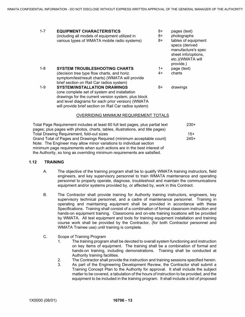
1X0000 (08/01) 16706 - 13
1-7 EQUIPMENT CHARACTERISTICS (including all models of equipment utilized invarious types of WMATA mobile radio systems)
8+8+8+
pages (text)photographstables of equipmentspecs (derivedmanufacture's specsheet info/options,etc.)(WMATA willprovide.)
1-8 SYSTEM TROUBLESHOOTING CHARTS(decision tree type flow charts, and horiz.symptom/test/result charts) (WMATA will providebrief section on Rail Car radios system)
1+4+
page (text)charts
1-9 SYSTEM/INSTALLATION DRAWINGS(one complete set of system and installationdrawings for the current version system, plus blockand level diagrams for each prior version) (WMATAwill provide brief section on Rail Car radios system)
8+ drawings
OVERRIDING MINIMUM REQUIREMENT TOTALS
Total Page Requirement includes at least 60 full text pages, plus partial textpages; plus pages with photos, charts, tables, illustrations, and title pages)
230+
Total Drawing Requirement, fold-out sizes 15+Grand Total of Pages and Drawings Required (minimum acceptable count) 245+Note: The Engineer may allow minor variations to individual sectionminimum page requirements when such actions are in the best interest ofthe Authority, so long as overriding minimum requirements are satisfied.
1.12 TRAINING
A. The objective of the training program shall be to qualify WMATA training instructors, fieldengineers, and key supervisory personnel to train WMATA maintenance and operatingpersonnel to properly operate, diagnose, troubleshoot and maintain the communicationsequipment and/or systems provided by, or affected by, work in this Contract.
B. The Contractor shall provide training for Authority training instructors, engineers, keysupervisory technical personnel, and a cadre of maintenance personnel. Training inoperating and maintaining equipment shall be provided in accordance with theseSpecifications. Training shall consist of a combination of formal classroom instruction andhands-on equipment training. Classrooms and on-site training locations will be providedby WMATA. All test equipment and tools for training equipment installation and trainingcourse work shall be provided by the Contractor, (for both Contractor personnel andWMATA Trainee use) until training is complete.
C. Scope of Training Program1. The training program shall be devoted to overall system functioning and instruction
on key items of equipment. The training shall be a combination of formal andhands-on training, including demonstrations. Training shall be conducted atAuthority training facilities.
2. The Contractor shall provide the instruction and training sessions specified herein.3. As part of the Engineering Development Review, the Contractor shall submit a
Training Concept Plan to the Authority for approval. It shall include the subjectmatter to be covered, a tabulation of the hours of instruction to be provided, and theequipment to be included in the training program. It shall include a list of proposed
WMATA CONFIDENTIAL INFORMATION - DO NOT DISCLOSE WITHOUT EXPRESS WRITTEN APPROVAL OF THE GENERAL MANAGER OF THE AUTHORITY

16706 - 14 1X0000 (08/01)
Contractor training to be conducted at various Authority facilities and locations. TheAuthority will select training sessions from this list.
D. Training Course Objectives1. The Contractor shall develop an individual Training Course designed to cover basic
maintenance of the Fiber Optic System using new Training Equipment Mockupssupplied by the Contractor.
2. The maintenance course shall provide each student with instruction designed tomeet the following objectives:a. Understanding of the basic overall operation of the Mockup as it relates to
an equivalent installed Passenger Station Communications subsystem.b. Understanding of the nature of each of the signal and power inputs and
outputs of major Communications equipment items.c. Knowledge of the location of all equipment test points and the best strategy
for using the test points.d. Familiarity with the Operation and Maintenance Manuals, and knowledge
of how to contact the equipment manufacturers for parts, and information.e. Qualification of the student to begin assuming maintenance (or operations)
responsibilities for the system and equipment items.
E. The Contractor’s training program shall be conducted by fully qualified instructors. Theinstructors shall have thoroughly mastered the specific specialized subject matter involvedand shall have the ability to impart technical information to others in easily understoodterms. The Contractor shall provide a professional resume for each instructor for review andapproval by the Authority. Contractor installation, repair and technical personnel shall alsobe provided to do installation tasks, with WMATA trainee participation (to the extent agreedto by the Engineer).
F. Training Aids and Materials1. The training shall be organized to make optimum use of Volume “B” O&M Manuals,
Contract Specifications and Drawings, approved Progress Review material,approved Contractor Shop Drawings, and the test equipment furnished to theAuthority, in accordance with other provisions of this Contract. The Contractor shallfurnish all other required training aids and materials necessary for the trainingprogram.
2. The Contractor shall provide copies of each Course Outline, copies of each LessonPlan, copies of Instructor’s Guide(s) and copies of Student Work Books.Operations and Maintenance Manuals, Volume “A” System Manuals and Volume“B” Equipment Manuals, furnished by the Contractor, shall be furnished to eachstudent attending the Maintenance Courses, along with additional copies asrequired.
3. Training materials, such as lesson plans, study guides, and student handouts, aswell as training aids, such as transparencies, slides, photographs, dynamicmockups, models for hands-on demonstration training and hardware cut-aways,utilized in the courses shall become property of the Authority.
G. WMATA requires the following training course materials to be delivered by the Contractor,according to the following specifications:1. An instructor’s guide, containing all the information and directions necessary for the
instructor to make an effective presentation. It shall include adequate guidelinesto conduct a comprehensive training program. Individual lessons within the courseshall be organized as separate blocks (or modules) which may be taughtindividually. The Instructor Guide should contain, at a minimum:a. Discussion of student prerequisites (if any);
WMATA CONFIDENTIAL INFORMATION - DO NOT DISCLOSE WITHOUT EXPRESS WRITTEN APPROVAL OF THE GENERAL MANAGER OF THE AUTHORITY
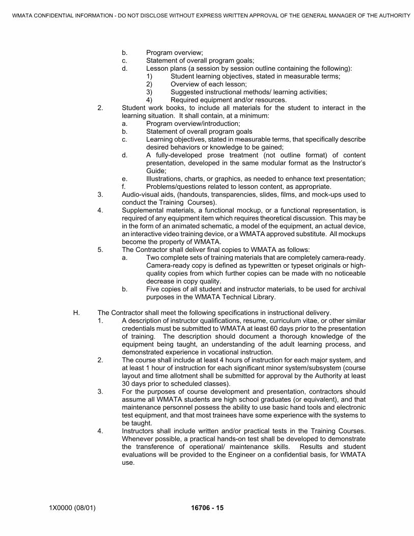
1X0000 (08/01) 16706 - 15
b. Program overview;c. Statement of overall program goals;d. Lesson plans (a session by session outline containing the following):
1) Student learning objectives, stated in measurable terms;2) Overview of each lesson;3) Suggested instructional methods/ learning activities;4) Required equipment and/or resources.
2. Student work books, to include all materials for the student to interact in thelearning situation. It shall contain, at a minimum:a. Program overview/introduction;b. Statement of overall program goalsc. Learning objectives, stated in measurable terms, that specifically describe
desired behaviors or knowledge to be gained;d. A fully-developed prose treatment (not outline format) of content
presentation, developed in the same modular format as the Instructor’sGuide;
e. Illustrations, charts, or graphics, as needed to enhance text presentation;f. Problems/questions related to lesson content, as appropriate.
3. Audio-visual aids, (handouts, transparencies, slides, films, and mock-ups used toconduct the Training Courses).
4. Supplemental materials, a functional mockup, or a functional representation, isrequired of any equipment item which requires theoretical discussion. This may bein the form of an animated schematic, a model of the equipment, an actual device,an interactive video training device, or a WMATA approved substitute. All mockupsbecome the property of WMATA.
5. The Contractor shall deliver final copies to WMATA as follows:a. Two complete sets of training materials that are completely camera-ready.
Camera-ready copy is defined as typewritten or typeset originals or high-quality copies from which further copies can be made with no noticeabledecrease in copy quality.
b. Five copies of all student and instructor materials, to be used for archivalpurposes in the WMATA Technical Library.
H. The Contractor shall meet the following specifications in instructional delivery.1. A description of instructor qualifications, resume, curriculum vitae, or other similar
credentials must be submitted to WMATA at least 60 days prior to the presentationof training. The description should document a thorough knowledge of theequipment being taught, an understanding of the adult learning process, anddemonstrated experience in vocational instruction.
2. The course shall include at least 4 hours of instruction for each major system, andat least 1 hour of instruction for each significant minor system/subsystem (courselayout and time allotment shall be submitted for approval by the Authority at least30 days prior to scheduled classes).
3. For the purposes of course development and presentation, contractors shouldassume all WMATA students are high school graduates (or equivalent), and thatmaintenance personnel possess the ability to use basic hand tools and electronictest equipment, and that most trainees have some experience with the systems tobe taught.
4. Instructors shall include written and/or practical tests in the Training Courses.Whenever possible, a practical hands-on test shall be developed to demonstratethe transference of operational/ maintenance skills. Results and studentevaluations will be provided to the Engineer on a confidential basis, for WMATAuse.
WMATA CONFIDENTIAL INFORMATION - DO NOT DISCLOSE WITHOUT EXPRESS WRITTEN APPROVAL OF THE GENERAL MANAGER OF THE AUTHORITY

16706 - 16 1X0000 (08/01)
1.13 SAMPLES
A. Samples For Review:1. Submitted to Engineer for review for the limited purpose of checking for
conformance with information given and the design concept expressed in thecontract documents.
2. After review, produce duplicates and distribute in accordance with SubmittalProcedures article above and for record documents purposes.
B. Samples For Information:1. Submitted for the Engineer's knowledge.
C. Samples For Selection:1. Submitted to Engineer for aesthetic, color, or finish selection.2. Submit samples of finishes from the full range of manufacturers' standard colors,
textures, and patterns for Engineer selection.3. After review, produce duplicates and distribute in accordance with Submittal
Procedures article above and for record documents purposes.
D. Submit samples to illustrate functional and aesthetic characteristics of the Product, withintegral parts and attachment devices. Coordinate sample submittals for interfacing work.
E. Include identification on each sample, with full Project information.
F. Submit the number of samples specified in individual specification sections, one of whichwill be retained by Engineer.
G. Reviewed samples that may be used in the Work are indicated in individual specificationsections.
H. Samples will not be used for testing purposes unless specifically stated in the specificationsection.
1.14 DESIGN DATA
A. Submitted for the Engineer's review.
B. Submit for information for the purpose of assessing conformance with information given andthe design concept expressed in the contract documents
1.15 TEST REPORTS
A. Submitted for the Engineer's review.
B. Submit test reports for information for the purpose of assessing conformance withinformation given and the design concept expressed in the contract documents.
1.16 CERTIFICATES
A. When specified in individual specification sections, submit certification by the manufacturer,installation/application subcontractor, or the Contractor to Engineer, in quantities specifiedfor Product Data.
B. Indicate material or Product conforms to or exceeds specified requirements. Submit
WMATA CONFIDENTIAL INFORMATION - DO NOT DISCLOSE WITHOUT EXPRESS WRITTEN APPROVAL OF THE GENERAL MANAGER OF THE AUTHORITY
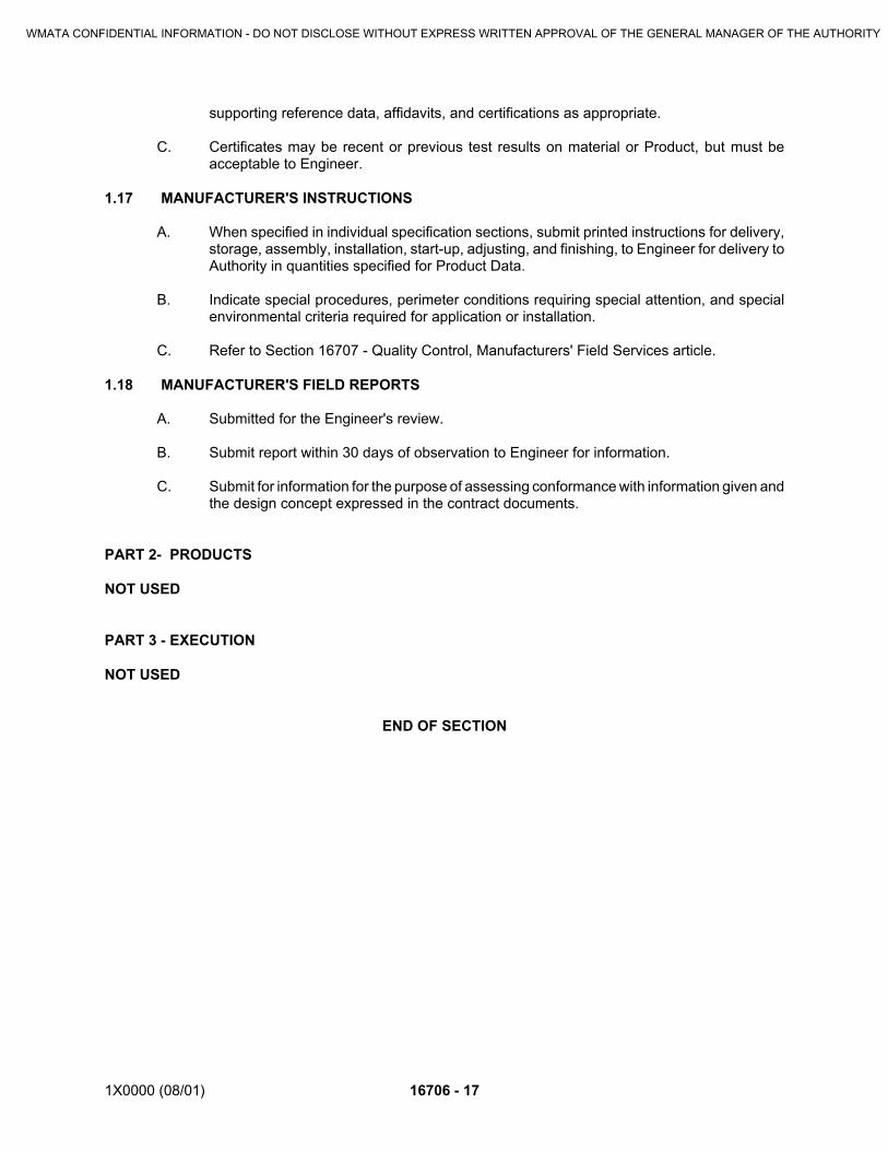
1X0000 (08/01) 16706 - 17
supporting reference data, affidavits, and certifications as appropriate.
C. Certificates may be recent or previous test results on material or Product, but must beacceptable to Engineer.
1.17 MANUFACTURER'S INSTRUCTIONS
A. When specified in individual specification sections, submit printed instructions for delivery,storage, assembly, installation, start-up, adjusting, and finishing, to Engineer for delivery toAuthority in quantities specified for Product Data.
B. Indicate special procedures, perimeter conditions requiring special attention, and specialenvironmental criteria required for application or installation.
C. Refer to Section 16707 - Quality Control, Manufacturers' Field Services article.
1.18 MANUFACTURER'S FIELD REPORTS
A. Submitted for the Engineer's review.
B. Submit report within 30 days of observation to Engineer for information.
C. Submit for information for the purpose of assessing conformance with information given andthe design concept expressed in the contract documents.
PART 2- PRODUCTS
NOT USED
PART 3 - EXECUTION
NOT USED
END OF SECTION
WMATA CONFIDENTIAL INFORMATION - DO NOT DISCLOSE WITHOUT EXPRESS WRITTEN APPROVAL OF THE GENERAL MANAGER OF THE AUTHORITY

1X0000 (08/01) 16707 - 1
SECTION 16707
COMMUNICATIONS SYSTEMS QUALITY ASSURANCE & TESTING
PART 1 - GENERAL
1.01 SECTION INCLUDES
A. These quality control (QC) system requirements define characteristics, in addition to thosein Division 1 of the Specification, of the quality control system that must be implemented bythe Contractor during the course of Communications System design, equipmentprocurement, factory testing, installation and acceptance testing.
B. The Contractor shall provide and maintain a Quality Assurance Plan, and an Inspection andTesting Plan covering the equipment, materials, and services specified herein.
C. The CQCS Quality Assurance Program, Quality Assurance Plan, and Inspection andTesting Plan, including related directives, procedures, processes, instructions, forms andschedules, shall be submitted to the Engineer for approval. The basis for approval shall bethe Engineer's acceptance of a document describing how the Quality Assurance Programrequirements, set forth herein, shall be met and the acceptance of the form and substanceof each document submitted for approval. The approved program and plans shall be usedby the Contractor in the performance of any inspection of the equipment, materials andservices being furnished. If program/plans are returned as unacceptable, the Contractorshall revise and resubmit the Quality Assurance Program or plans to the Engineer within30 calendar days.
D. The basis for this quality control (QC) system requirements are the American NationalStandards Institute (ANSI) Standard ANSI/ISO/ASQC Q9002-1994 entitled "QualitySystems -Model for Quality Assurance in Production and Installation and Servicing.."Quality control systems based on other standards may also be acceptable provided theycontain elements that meet these requirements.
1.02 RELATED SECTIONS
A. Division 1
B. Division 16 - Communications Sections
1.03 REFERENCES
A. American National Standards Institute (ANSI) Standard ANSI/ISO/ASQC Q9002-1994
1.04 DEFINITION OF TERMS
A. Quality Assurance Program: The document containing the Contractor's quality-relatedpolicies, practices, procedures and methods, which are utilized to assure compliance withContract Specifications.
B. Quality Assurance Plan: A document detailing how the Contractor will implement the QualityAssurance Program
WMATA CONFIDENTIAL INFORMATION - DO NOT DISCLOSE WITHOUT EXPRESS WRITTEN APPROVAL OF THE GENERAL MANAGER OF THE AUTHORITY

16707 - 2 1X0000 (08/01)
C. Inspection and Test Plan: A document detailing how the Contractor will inspect and testContract equipment, materials, workmanship, and services.
D. Inspection: The physical act of verifying, by measurement and examination of theequipment, materials, workmanship, and services, that they conform to approveddocuments and established quality requirements.
E. Audit: An examination of the Contractor's implementation of the approved QualityAssurance Program for the purpose of determining compliance with and conformance tothe Quality Assurance Plan and other related documents.
1.05 QUALITY POLICY
A. The Supplier shall establish and document policies to implement quality controlsystematically in a manner that meets these QC system requirements. These policies shallbe revised or amended until they are accepted by the Engineer.
1.06 QUALITY SYSTEM
A. The Contractor shall document and implement a quality control system consistent with thepolicies accepted by the Engineer. The quality system shall include:1. Written procedures and instructions governing the work covered by this contract.2. Effective and verifiable implementation of these procedures and instructions.
B. Activities affecting quality shall be prescribed via documented instructions, procedures, ordrawings of a type appropriate to the circumstances and shall be accomplished inaccordance with these instructions, procedures, or drawings.
C. Instructions, procedures, or drawings shall include appropriate measurable or otherwiseverifiable criteria for determining that important activities have been satisfactorilyaccomplished.
1.07 ORGANIZATION
A. The submitted Quality Assurance Program document shall be organized as follows:1. Name of Contractor and Contract2. Revision Dates3. Index4. Contents
B. The Contractor shall identify the elements of its organization involved with this Contract,including subcontractors and Original Equipment Manufacturers (OEMs), and the scope ofresponsibility and authority of these parties.
C. Interfaces with OEMs, subcontractors, and WMATA shall be identified and the scope ofeach group's responsibilities described
D. The responsibility, authority and the interrelation of personnel who manage, supervise,perform and verify work affecting the quality of items intended for WMATA shall be defined,particularly for personnel who must exercise authority to:1. Initiate, recommend or provide solutions through designated channels to eliminate
identified noncompliance or nonconformance,2. Control further processing, delivery or installation of items until the noncompliance
or nonconformance has been corrected, and
WMATA CONFIDENTIAL INFORMATION - DO NOT DISCLOSE WITHOUT EXPRESS WRITTEN APPROVAL OF THE GENERAL MANAGER OF THE AUTHORITY

1X0000 (08/01) 16707 - 3
3. Initiate action to prevent the occurrence of noncompliance or nonconformance.
E. Inspection and testing functions shall have sufficient resources and organizationalindependence to perform their responsibilities. Except in-process monitoring, they shall notreport to the same management as those who performed the work nor have had input asto how the work was accomplished or accepted.
1.08 SCOPE
A. The Contractor shall provide a statement that identifies the functional areas of Contractorwork and the locations where such work is performed. The Quality Assurance Programshall apply to all equipment, systems, and services included in these Specifications, exceptas otherwise stated. The Contractor's functional work area breakdown shall include, butshall not be limited to, management, engineering, procurement, manufacturing, installation,and inspection.
1.09 SUBMITTALS
A. The Quality Assurance documents shall be submitted within 30 calendar days after Notice-To-Proceed. Contractor test and inspection procedures shall be added to the approvedQuality Assurance Program within 30 days after they are developed. Details concerningfabrication processes for equipment and systems that require development shall be addedto the approved Quality Assurance Program as the development work progresses (within30 days after they are developed).
1.10 DELIVERY, STORAGE AND HANDLING
A. The Contractor shall establish and implement measures for maintaining the integrity,security, and acceptability of items during receiving, handling, storage, movement orplacement of items.
B. The Contractor shall maintain packing and preservation of items to the extent necessaryto ensure conformance with this contract until these items are installed. The packaging ofitems inspected at the receiving point shall be resealed upon completion of the inspection.
C. The Contractor shall provide secure storage areas to prevent loss of, damage to, ordeterioration of items pending their use:1. Items of different types shall be segregated while in storage;2. Measures shall ensure that the shelf life of items which deteriorate over time are
reported, and that those with expired shelf life are scrapped;3. Special environment, maintenance (when items are stored for long periods), and
stacking limits required by the manufacturer shall be observed.4. In order to detect deterioration, the condition of items in storage shall be checked
and assessed at appropriate intervals.5. Appropriate methods shall be established for authorizing receipt or release of items
at these storage areas.
D. Handling1. The Contractor shall employ qualified personnel, methods and equipment to
prevent damage during handling.2. Handling equipment and rigging shall be periodically inspected, maintained and
tested. Load capacities or ratings shall be visible on the equipment; capacities andratings shall not be exceeded.
WMATA CONFIDENTIAL INFORMATION - DO NOT DISCLOSE WITHOUT EXPRESS WRITTEN APPROVAL OF THE GENERAL MANAGER OF THE AUTHORITY

16707 - 4 1X0000 (08/01)
3. Operators shall be trained, and, where required by local codes or elsewhere in thiscontract, certified. WMATA requirements and rules for use of handling equipmentshall also be observed at all WMATA properties, leased premises, or constructionsites.
PART 2 - PRODUCT
NOT USED
PART 3 EXECUTION
3.01 QUALITY MANAGEMENT
A. The Contractor shall identify and describe the organizational units having responsibility andauthority for development, implementation, and management of the Quality AssuranceProgram. Achievement of quality objectives shall be verified by individuals andorganizations that are responsible for checking, inspecting, auditing, or otherwise verifyingthat the work has been performed satisfactorily.
B. The Contractor shall identify the program for assuring that sufficient records are maintainedto provide documentary evidence of the performance of activities affecting quality and foruse in managing the Contract. Typical records shall include Quality Assurance plans,procedures, instructions, nonconformance or defect reports, corrective action reports, andsuch other quality-related documents as are specified in the Contract Specifications.
C. The Contractor shall identify the program for verifying and determining the cause ofunsatisfactory product or workmanship quality and for initiating necessary improvementsand corrections to preclude repetition. The Contractor's program should extend, whennecessary, to the performance of subcontractors and suppliers.
3.02 DESIGN (AND DEVELOPMENT)
A. The Contractor shall prepare and maintain a plan for inspecting the quality of engineering,development, testing, and documentation activities. The Contractor shall identify theprocedures, practices, tables, charts and diagrams applicable to the effort.
B. The Contractor shall document the engineering criteria applicable to the product beingsupplied. Include performance objectives, operating ranges and conditions, requirementsfor safety, reliability, availability, the requirements (codes, standards, and practices) formaterials, fabrication, construction, testing, operation, maintenance, and quality assurance.
C. Studies, to be conducted in support of the engineering (or development) activity, shall beidentified by the Contractor. They shall include analysis of allowable "tradeoffs" andalternatives, identification of potential weaknesses, and the appropriate preventativeengineering features, operating and maintenance practices, and safety precautions.
D. The Contractor shall identify the program for assuring that specifications, drawings, andother engineering documents will delineate, as applicable:1. Materials and methods, including fabrication, construction, installation, inspection,
maintenance cleaning, packaging, shipping, handling, and storage.2. Traceability of materials, parts, components, and processes through appropriate
lot, piece part, serial, or other appropriate numbers.3. Product or workmanship acceptance criteria and the checkpoints during the work
process for verifying compliance with the criteria.
WMATA CONFIDENTIAL INFORMATION - DO NOT DISCLOSE WITHOUT EXPRESS WRITTEN APPROVAL OF THE GENERAL MANAGER OF THE AUTHORITY

1X0000 (08/01) 16707 - 5
E. The Contractor shall identify the methods and procedures for defining and controllingengineering interfaces with other project participants and design organizations. Theprocedures shall cover the exchange of required engineering data, analysis and resolutionof engineering interface problems.
F. The Contractor shall identify procedures for controlling release of documents for authorizeduse.
G. The Contractor shall identify procedures for documenting the reporting, verifying, analysis,and correcting of troubles that occur during development.
H. Design criteria and input, including computer applications software, shall be identified,documented, and their selection reviewed by those responsible for the technical adequacyof the design. In all cases, the names of the preparer, checker, and the date the checkeraccepted the document shall be shown.
I. Incomplete, ambiguous, or conflicting requirements shall be resolved by those who drewup the design criteria and input and those who approved their selection.
J. The design input obtained from surveys of existing systems, structures, or facilities shall bedocumented and identified.
K. Design output (calculations, specifications, and drawings) shall be documented asrequirements in a clear, logical, and uniform manner.
L. In all cases, the names of the preparer, checker and the date the checker accepted thedocument shall be shown.
M. Where required by the applicable Code, design standard, or this contract, design outputshall be certified and/or sealed by the appropriate professional practitioner.
N. The calculation method or computer program shall be identified (including computersoftware version). The reference source of special, state-of-the-art, or experimentalfeatures that are not widely accepted in the railroad industry shall also be identified andthose features briefly summarized.
O. Where the design output is a computer or computer software, specifications, user manuals,and testing and validation files shall be provided. Where the contract conveys to WMATAthe license to duplicate, upgrade, repair, and modify the computer or computer code,detailed schematic diagrams, specifications, any special tools, and working standards shallbe provided to enable the exercise of the license.
P. The design shall be verified to have met the requirements of this Contract. Designverification shall be documented and may take the form of design review, checking,alternative analysis or calculation, comparison with proven design, or performance ofqualification tests and demonstrations. Design verification documentation. (including OEMequipment qualification testing) shall be made available to the Engineer upon request.
Q. The Contractor shall establish and implement measures to identify, control, and assess theimpact of proposed design changes (including those from the OEMs) on specifiedfunctional, safety, and quality requirements, and added cost and schedule changes areidentified and justified.
WMATA CONFIDENTIAL INFORMATION - DO NOT DISCLOSE WITHOUT EXPRESS WRITTEN APPROVAL OF THE GENERAL MANAGER OF THE AUTHORITY

16707 - 6 1X0000 (08/01)
R. Design changes shall be reviewed, verified and approved in the same manner as theoriginal version. The Contractor shall assign qualified personnel to review and coordinatedesign changes.
S. The Contractor shall obtain the Engineer's approval of proposed changes prior toimplementing these.
3.03 DOCUMENT CONTROL
A. The Contractor shall establish and implement measures to control reports, procedures,contract technical deliverable documents, OEM and subcontractor technical submittals, andother records and information it generates or receives that relate to equipment performancecharacteristics, qualification testing, factory testing, installation, inspection, and acceptancetesting. This control shall ensure that:1. The latest, approved versions of documents or information described above are
available where affected Supplier's activities are performed.2. Revised documents are redistributed to those who received the previous issue.3. Superseded or obsolete documents are promptly removed from areas of work and
stations where controlled documents must be distributed.4. Changes are reviewed and approved by the same functions or organizations that
performed the original review and approval or their designated successors.5. A means (such as a list or computerized database) to identify the current revision
of instructions, procedures, drawings, specifications, or calculations is available.6. Communications (memorandums of meetings, requests for clarification, etc.) and
reports are issued or responded to in a timely manner.
B. The Contractor shall establish and implement measures to revise and maintain proceduresand other records that relate to the performance characteristics, installation, inspection, andtesting of components, equipment, or systems in an updated condition. Current as-builtcondition of equipment shall be retained on file.
C. Purchasing documents shall contain data clearly describing the product ordered, including,where applicable:1. The type, class, style, grade, or other precise requirements,2. The title, number designation and revision of specifications, drawings, process
requirements, inspection/test requirements and other relevant technical and qualitycontrol requirements, including requirements for approval or qualification ofproduct, procedures, process or inspection equipment and personnel.
3. The title, number and revision of any applicable technical and quality standards tobe applied to the product.
4. As a minimum, OEMs shall be required to furnish Certificates of Conformance tothe design and manufacturing standards specified by the Supplier, together with theequipment supplied.
3.04 PROCUREMENT
A. The Contractor shall identify the procedures for controlling the receipt, inspection, testing,handling, storage, and distribution of received equipment and its protection from damage,deterioration, loss or substitution. Inspection instructions and test procedures shall providefor verification of characteristics required by the Contract Drawings and Specifications, anddocumentation of results.
WMATA CONFIDENTIAL INFORMATION - DO NOT DISCLOSE WITHOUT EXPRESS WRITTEN APPROVAL OF THE GENERAL MANAGER OF THE AUTHORITY

1X0000 (08/01) 16707 - 7
B. The Contractor shall identify the procedures for controlling purchased items that do notconform to Specifications. The procedures shall provide for prompt identification,documentation, segregation, technical review, and disposition of non-conforming items.
C. The Contractor shall establish and implement measures for obtaining items and servicesfrom suppliers or subcontractors that conform with specified requirements:1. The Contractor shall select its OEMs, subcontractors and other sub-suppliers on
the basis of their ability to meet specified requirements2. Any procurement requirement which differs from those in the selected OEM,
subcontractor, or other sub-supplier's proposal or offer is resolved and theresolution incorporated into the purchase order or contract, and
3. Records are maintained to show acceptability of the selected OEM, subcontractor,or other sub-supplier (where available, records of previously demonstratedcapability and performance should be provided to show acceptability of theselected supplier).
3.05 MANUFACTURING, FABRICATION, AND ASSEMBLY
A. The Contractor shall identify the procedure and instructions that will be used to assure thatfabrication, processing, and assembly operations are being satisfactorily performed.
B. The Contractor shall identify the inspection and test plans that will be applied to allmanufacturing activities for the purpose of verifying conformance to procedures andinstructions.
C. The Contractor shall identify the method employed for tracing the identity of materials anditems throughout fabrication, processing, or assembly operations.
D. The Contractor shall identify the procedures, instructions, and checklists for the control ofthe fabrication and assembly processes. This shall include such items as shop orders,process sheets, travelers, and inspection instructions, covering all mechanical, electrical,and metallurgical processes. Inspection instructions shall identify the nondestructiveexamination processes employed.
E. The Contractor shall identify the methodology of the program including record maintenance.
F. The Contractor shall identify the procedures for prompt identification, documentation,segregation, technical review, and disposition of non-conforming items.
G. The Contractor shall identify the procedures and instructions for handling, preserving,packing, packaging, storing, and shipping items shipped to the construction site.
3.06 INSTALLATION
A. The Contractor shall identify the procedures, check off lists, and instructions governingreceipt inspection of equipment on arrival at the construction site. The Contractor shallinclude in the procedures the control of non-conforming items.
B. The Contractor shall identify the procedures for on-site configuration control. This shallinclude the control of drawings, specifications, work instructions, quality-control procedures,inspection instructions, and testing procedures, used in connection with installation.
C. The Contractor shall identify the procedures and work instructions that apply to installationmethods, tests, repairs and rework, cleaning and protection.
WMATA CONFIDENTIAL INFORMATION - DO NOT DISCLOSE WITHOUT EXPRESS WRITTEN APPROVAL OF THE GENERAL MANAGER OF THE AUTHORITY

16707 - 8 1X0000 (08/01)
D. The Contractor shall identify the inspections and tests to be performed to verify installationsuitability.
E. The Contractor shall identify the procedures for controlling the on-site identification,documentation, segregation, technical review, and disposition of non-conforming suppliesor workmanship.
3.07 INSPECTION AND TESTING
A. The Contractor shall establish and implement a Unified Test Program that will ensure allcommunications and related systems, equipment, material and services, furnished duringthe performance of this Contract, meet the technical requirements and standards specified,as well as all performance criteria.
B. As part of the Contractor's area of responsibility for the Unified Test Program, theContractor will be required to:1. Develop a comprehensive Test Plan detailing methods and test procedures to be
utilized to ensure compliance with all applicable specifications.2. Develop detailed test procedures for each individual test within each category of
testing, except Authority tests.3. Submit the Test Plan (including Authority System Validation Tests, Substantial
Completion Acceptance, and Final Acceptance Programs) and all test proceduresto the Engineer for evaluation, review, and acceptance or rejection. Revise andresubmit until acceptance by the Engineer is received.
4. Furnish personnel, calibrated test equipment, tools, and miscellaneous supplies asnecessary to perform all tests and retests, and to maintain all systems andequipment during the test period and until acceptance by the Authority.
5. Coordinate Unified Test Program activities with the schedules and activities of othercontractors and with the Engineer, to avoid conflicts with Authority operationalrequirements.
6. Perform tests and inspections as detailed in all approved test procedures.7. Evaluate test procedure and inspection results and documentation. Prepare
detailed test evaluation reports, summary reports and progress reports.8. Submit all raw test data, test results, evaluations, and summary reports for
evaluation, review and acceptance or rejection by the Engineer.9. Prepare and submit revised test procedures and test plans to correct procedural
and technical errors or omissions discovered in those documents, after their initialAuthority acceptance.
10. Furnish corrective actions to effect Specification compliance, including: Remedytest program deficiencies, and system, equipment, material, workmanship, anddocumentation deficiencies promptly upon request by the Engineer.
11. Perform retesting and additional inspections until successful results are obtained,evaluated, and accepted by the Engineer.
12. Participate in Authority Pre-final Inspections, Substantial Completion (if any), andFinal Acceptance activities. Clean the equipment and work site, secure theequipment, and remain responsible for prompt repair or replacement in the eventof loss or damage until acceptance by the Authority is received. Furnish inventoryservices and demonstrate system or equipment operation in support of requestsby the Authority. Provide support and access so that the Authority Engineers,Technicians, Mechanics and Inspectors can inspect and test any portion of thework during normal work hours.
WMATA CONFIDENTIAL INFORMATION - DO NOT DISCLOSE WITHOUT EXPRESS WRITTEN APPROVAL OF THE GENERAL MANAGER OF THE AUTHORITY

1X0000 (08/01) 16707 - 9
13. Provide Unified Test Program reports on a monthly basis beginning within 30 daysafter the Engineer's acceptance of the Test Plan, and continuing until the finalcompletion of all contract work.
C. The performance of each task requirement shall be subject to the Engineer's acceptanceof methods, procedures, and results, for Specification compliance, and as to scheduling forthe benefit of the Authority.
D. A Preliminary Test Plan shall be submitted to the Engineer for review. Subsequently, theFinal Test Plan shall be submitted to the Engineer for review and acceptance or rejection.In the event of rejection or subsequent rejections, corrected re-submissions shall bedelivered to the Engineer within 15 days after the receipt of each rejection. An acceptedTest Plan shall be required prior to implementing any category of tests except for factorytests and inspections, installation and completion tests, inspections for cable, andassociated terminal equipment, which may be accepted on an individual basis forequipment, and materials that are scheduled to be installed or delivered prior to NTP + ###.
E. Detailed test procedures shall be submitted to the Engineer for review and acceptance orrejection. In the event of rejection or subsequent rejections, corrected re-submissions shallbe delivered to the Engineer within 15 days after receipt of each rejection. Approved testprocedures shall be required prior to commencing any associated test.
F. Each individual test procedure shall include, but not be limited to: An outline of testobjectives, detailed step-by-step procedures with required results and allowable tolerancesfor each measurement or observation, diagrams illustrating all required test set-ups,manufacturer and model number of each unit and accessory item of required testequipment, and further details as may be required by the Engineer to ensure that bothContractor and Authority field forces are presented with a totally comprehensive,understandable and accurate working procedure.
G. The Contractor shall include complete and adequate safety procedures, warnings, andemergency instructions in Test Plans and test procedures, as appropriate. Test proceduresshall also include complete examples of test Data Record Forms with required resultantvalues and allowable tolerances, in accordance with Specification requirements.
H. The Authority reserves the right to perform additional non-destructive tests and inspectionsat any time during the course of the contract work. Results indicating deficiencies involvingnoncompliance with Specification requirements will be reported to the Contractor forcorrective action.
3.08 DEFICIENCIES
A. If the Engineer determines from test data acquired from any category of test(s) that thesystem, equipment, materials, technical documentation, or services furnished do notconform to any Specification requirement(s), the Contractor shall recommend appropriateremedial action based on an analysis of test results within fifteen days after receipt of theEngineer's notice of deficiency. When such recommendations relate to engineeringdeficiencies, the Contractor shall, upon receipt of the Engineer's approval, make thenecessary changes to all equipment and documentation of the type to be delivered orpreviously delivered (even if previously accepted) during the course of the Contract, at noadditional cost to the Authority.
B. When recommendations relate to other deficiencies such as quality control and installationworkmanship, the Contractor shall correct all deficiencies at each location, at no additional
WMATA CONFIDENTIAL INFORMATION - DO NOT DISCLOSE WITHOUT EXPRESS WRITTEN APPROVAL OF THE GENERAL MANAGER OF THE AUTHORITY

16707 - 10 1X0000 (08/01)
cost to the Authority. Retesting after the changes have been completed (Factory Tests andInspections, Installation Completion Tests and Inspections, and Technical DocumentationVerifications) shall be required in whole or part, as determined by the Engineer, at noadditional cost to the Authority. If the timely correction of all deficiencies is not completedto effect Specification compliance, as evidenced by the Engineer's acceptance of retestresults, the Engineer will initiate remedial actions to the benefit of the Authority. Suchactions may include the exercise of warranty, correction of deficiency, delay of payments,disputes or default, and termination actions, in accordance with the General Provisions, oractions of benefit to the Authority, in accordance with any combination of these and otherSpecification provisions.
3.09 CATEGORIES OF TESTS
A. Tests and inspections shall be required in each of seven categories, as listed below:1. Factory tests and inspections, including factory certifications and factory calibration
certifications.2. Installation completion tests and inspections.3. System and integration tests.4. System validation tests and evaluations (Authority Conducted Program).5. Substantial Completion acceptance tests and inspections (if any) (Authority
Conducted Program).6. Technical documentation verification inspections.7. Final acceptance tests and inspections (Authority Conducted Program).
B. Each test and inspection in each category shall be comprehensive, so that sufficient testresult data and inspection result data is furnished to permit complete detailed examinationand evaluation, as determined by the Engineer.
C. Additional specialized testing shall also be furnished, as defined in individual systemspecification Sections .
D. Retesting, and the acceptance or rejection of test results, documentation, and evaluations,shall be within the discretion of the Engineer.
3.10 FACTORY TESTS AND INSPECTIONS
A. All equipment and materials, including custom developed Additional Equipment and anycustom developed Test Equipment, furnished in accordance with these Specifications, shallbe subject at all times and during all stages of manufacture and assembly, to inspection,test, and rejection by the Engineer. The Engineer may elect to accept factory or Contractorcertifications in lieu of complete test result data for certain items when, 1) a WMATAaccepted factory test has been previously conducted on one or more production samplesor identical deliverable products, 2) the same brand and model of the product to befurnished has proven reliable in Authority revenue service for one year or more, or 3) tosimplify test program administration when not adverse to achieving Test Programobjectives.
B. Before offering items for inspection or test, the Contractor shall furnish a complete set ofapplicable drawings for Authority use including, but not limited to, schematics, wiringdiagrams, major assembly drawings, manufacturing drawings for custom developedequipment, and detailed specifications for the equipment and materials to be tested.
C. The Contractor shall submit Factory Test and Inspection Plans and Procedures to theEngineer for review. Tests required shall be performed at the point of manufacture and the
WMATA CONFIDENTIAL INFORMATION - DO NOT DISCLOSE WITHOUT EXPRESS WRITTEN APPROVAL OF THE GENERAL MANAGER OF THE AUTHORITY

1X0000 (08/01) 16707 - 11
point of assembly before shipment to the field. The Contractor shall furnish additionaltesting by an independent testing laboratory if the manufacturer's Factory Test Plan orProcedures are determined by the Engineer to be inadequate to verify Specificationcompliance (a maximum of three major items may be designated by the Engineer forindependent laboratory testing at no additional cost to the Authority).
D. After the Engineering Development Review for each system has been submitted andapproved by the Engineer, Factory Tests and Inspections shall be scheduled for majoritems, custom prototypes, and other items of equipment and material designated for suchtesting by the Engineer, to verify compliance with environmental criteria, quality assurance,specified performance, grade of components, reliability, and workmanship includingmanufacturing processes. The Contractor shall advise the Engineer, in writing, whenmanufacturing of equipment begins and again two weeks prior to date of scheduledinspection or tests.
E. A "Report of Factory Visit" for the purpose of confirmation and subsequent agreement ofany decisions made on site shall be prepared by the Contractor and submitted to theEngineer ten working days subsequent to each factory visit by the Contractor, Engineer, ordesignated Authority Representative. Each report shall include the purpose of the visit,summary of tests performed and decisions made or required prior to factory certificationand shipment.
F. Two copies of test results certified by the manufacturer or an independent laboratory shallbe furnished to the Engineer for review and acceptance or rejection prior to shipment.Equipment shall not be shipped before the factory test results have been accepted by theEngineer. Optionally, the Authority may elect to accept Contractor certified test andinspection results in lieu of manufacturer or independent laboratory certified test results.
G. A 200 hour burn-in period (power on - attended or unattended) shall be required for all unitsof electrically operated and powered custom-made major items of equipment prior toinstallation, in accordance with instructions from the Engineer. Each unit of custom madeequipment shall be set up and powered on the Contractor's, Subcontractor's, or supplier'spremises. Reports of such activity shall be furnished to the Engineer.
H. The Contractor shall assemble all of the rack-mounted equipment for a Passenger StationCommunications Equipment Room and test prior to shipment to the installation site.
3.11 INSTALLATION COMPLETION TESTS AND INSPECTIONS
A. Installation Completion Tests and Inspections shall be performed after installation to ensurethat equipment and materials were not damaged in shipment and that they are properlyinstalled and functioning in accordance with specified criteria, parameters and goodcommercial practice. Installation Completion Tests and Inspections shall consist of:1. Visual inspection with check-off lists to verify the following:
a. That full compliance with requirements detailed in the General Equipmentand Material Standards and General Installation Standards sections ofthese Specifications has been meet.
b. That only approved products have been used.c. That Factory Tests and Inspections have been satisfactorily completed for
major items, as required.d. That inventory of major equipment and material items is available and
accurate.e. That equipment is installed in agreement with approved installation shop
drawings.
WMATA CONFIDENTIAL INFORMATION - DO NOT DISCLOSE WITHOUT EXPRESS WRITTEN APPROVAL OF THE GENERAL MANAGER OF THE AUTHORITY

16707 - 12 1X0000 (08/01)
f. That wire and cable terminations as to location, cable identification,routing, color code, and workmanship have been identified.
g. That Time Domain Reflectometry (TDR) measurements of all coaxial andoutside plant cables have been made. Printed TDR records of eachcoaxial and outside plant cable shall be delivered to the Authority toillustrate the length of cable run (proven by demonstrating an open and ashort condition before final termination), and the absence of any detectablefaults on each coaxial cable and each outside plant cable pair afterinstallation of the cable.
2. Detailed testing shall be required to demonstrate that material and equipmentinstalled meet the criteria and possess the characteristics and parameterscontained in the Contract Specifications; including additional requirements andstated tolerances that are specified in Contractor engineering and product approvaldata submissions and in manufacturer's published specifications attributed toapproved products.
B. The testing of all items of equipment and material shall include electrical, mechanical,operational, and functional parameters. Such parameters include, but are not limited to:Levels of voltages, currents, power, distortion, noise, cross-talk, insulation resistance,continuity, attenuation (optical and electrical), physical strength, suitability of mountingmethod, paint and marking quality, graphics quality and style, location of operating controlsand adjustments, and maintainability.
C. These tests shall be performed after the installation of material and equipment and shall bein addition to any Factory Tests and Inspections previously performed. The Contractor shallperform all necessary alignments, adjustments, and maintenance prior to requesting thescheduling of Installation Completion Tests and Inspections.
D. The Contractor shall advise the Engineer, in writing, two weeks prior to the date(s) ofscheduled tests and inspections. The Engineer will witness these tests. Two certifiedcopies of Installation Completion Test and Inspection data shall be submitted to theEngineer within seven (7) days after test completion for review and acceptance or rejection.
3.12 SYSTEM AND INTEGRATION TESTS
A. System and Integration Tests shall be on-site performance tests to verify that all operatingparameters and functions perform as specified and that each system performs as specifiedin conjunction with each system or subsystem with which it interfaces. The Contractor shalldemonstrate that all material and equipment elements of each installed system functiontogether to meet the system criteria specified. Each system shall be powered a minimumof 48 hours prior to commencing system and integration tests. The Engineer shall benotified, in writing, seven (7) days prior to equipment being powered. Failures shall berecorded by the Contractor and findings furnished to the Engineer at the end of the 40hours. The Contractor shall also include a description of corrective actions taken.
B. The Contractor shall be responsible for meeting all System and Integration Testrequirements including testing and documenting interface compatibility and integration withexisting Authority-owned systems and equipment.
C. Each and every interface shall be verified as to operation, function, level, and voltage. TheContractor shall test across the interface points; however, these tests shall only be madeunder the supervision of appropriate Authority personnel. When minor adjustment to, orreconfiguration of, existing equipment is required, the Contractor shall notify the Engineer,in writing, of the required adjustment or reconfiguration. Authority personnel will make the
WMATA CONFIDENTIAL INFORMATION - DO NOT DISCLOSE WITHOUT EXPRESS WRITTEN APPROVAL OF THE GENERAL MANAGER OF THE AUTHORITY

1X0000 (08/01) 16707 - 13
adjustment or reconfiguration in the presence of the Contractor. The Contractor shall beresponsible for the necessary adjustments or reconfigurations of Contractor-furnishedequipment to ensure proper functioning, as specified.
D. The successful completion of all specified Factory Tests and Inspections, and InstallationCompletion Tests and Inspections, including the correction of all outstanding discrepanciesand subsequent retesting, is required as a prerequisite to System and Integration Tests.
E. The tests will vary with each specific system. However, each test shall include all operatingparameters and functions. Tests shall be conducted on a location-by-location basis withall failures and discrepancies noted. The Contractor shall not engage in further testing untilthe Engineer has verified that the Contractor has taken necessary corrective action withrespect to those failures and discrepancies. The Contractor shall retest after eachsuccessive failure and corrective action to verify Specification compliance.
F. The Contractor shall advise the Engineer, in writing, two weeks prior to the date(s) ofscheduled tests. Prior to commencing the System and Integration Tests, the Contractorshall provide failures recorded and corrective action taken, at the conclusion of poweringequipment a minimum of 40 hours. The Engineer will witness these tests. Two certifiedcopies of System and Integration Test data sheets shall be submitted to the Engineer withinseven (7) days after test completion for review and acceptance or rejection.
3.13 MEASURING AND TEST EQUIPMENT
A. The Contractor shall establish and implement measures for the selection, calibration, andcontrol of measuring and test equipment (M&TE) used to determine conformance.
B. M&TE of a range, accuracy, and sensitivity conforming with measurement tolerancesspecified within this contract shall be selected and used.
C. Calibration procedures shall require M&TE identification and establish frequency ofcalibration, calibration method, acceptance criteria, records to be generated, and the actionto be taken when results are unsatisfactory.
D. M&TE shall be periodically calibrated using certified references traceable to the NationalInstitute of Standards and Technology (NIST), to other nationally recognized standardswhen no such NIST standards exist, or to a documented standard acceptable to theEngineer when none of the preceding standards exist.
E. The calibration of M&TE shall be checked at prescribed intervals if testing or inspection willcontinue over an extended period.
3.14 INSPECTION AND TEST STATUS
A. The Contractor shall establish and implement measures to identify and maintain theinspection and test status of systems, equipment or components until these are acceptedby the Engineer, to ensure that only purchased items that have passed the requiredinspection and test have been used.
B. The means for status identification shall be such that the surface of the item is not damagednor its use impaired. Status identification may also be via inspection records, test software,physical location, or other suitable means, which indicate the conformance ornonconformance of these items with regard to inspection and tests performed.
WMATA CONFIDENTIAL INFORMATION - DO NOT DISCLOSE WITHOUT EXPRESS WRITTEN APPROVAL OF THE GENERAL MANAGER OF THE AUTHORITY
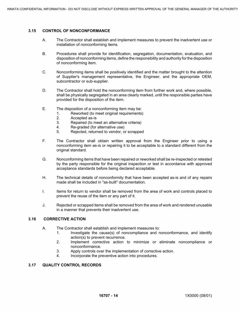
16707 - 14 1X0000 (08/01)
3.15 CONTROL OF NONCONFORMANCE
A. The Contractor shall establish and implement measures to prevent the inadvertent use orinstallation of nonconforming items.
B. Procedures shall provide for identification, segregation, documentation, evaluation, anddisposition of nonconforming items, define the responsibility and authority for the dispositionof nonconforming item.
C. Nonconforming items shall be positively identified and the matter brought to the attentionof Supplier's management representative, the Engineer, and the appropriate OEM,subcontractor or sub-supplier.
D. The Contractor shall hold the nonconforming item from further work and, where possible,shall be physically segregated in an area clearly marked, until the responsible parties haveprovided for the disposition of the item.
E. The disposition of a nonconforming item may be:1. Reworked (to meet original requirements)2. Accepted as-is3. Repaired (to meet an alternative criteria)4. Re-graded (for alternative use)5. Rejected, returned to vendor, or scrapped
F. The Contractor shall obtain written approval from the Engineer prior to using anonconforming item as-is or repairing it to be acceptable to a standard different from theoriginal standard.
G. Nonconforming items that have been repaired or reworked shall be re-inspected or retestedby the party responsible for the original inspection or test in accordance with approvedacceptance standards before being declared acceptable.
H. The technical details of nonconformity that have been accepted as-is and of any repairsmade shall be included in "as-built" documentation.
I. Items for return to vendor shall be removed from the area of work and controls placed toprevent the reuse of the item or any part of it.
J. Rejected or scrapped items shall be removed from the area of work and rendered unusablein a manner that prevents their inadvertent use.
3.16 CORRECTIVE ACTION
A. The Contractor shall establish and implement measures to:1. Investigate the cause(s) of noncompliance and nonconformance, and identify
action(s) to prevent recurrence.2. Implement corrective action to minimize or eliminate noncompliance or
nonconformance.3. Apply controls over the implementation of corrective action.4. Incorporate the preventive action into procedures.
3.17 QUALITY CONTROL RECORDS
WMATA CONFIDENTIAL INFORMATION - DO NOT DISCLOSE WITHOUT EXPRESS WRITTEN APPROVAL OF THE GENERAL MANAGER OF THE AUTHORITY

1X0000 (08/01) 16707 - 15
A. The Contractor shall establish and implement measures to identify, collect, index, file, andstore quality control records as required in the Special Conditions of this Contract.
B. Quality control records shall be available at designated, controlled, but accessible areas atwork locations. Procedures shall identify the responsible custodians for these records.
C. Quality control records shall be stored and maintained in such a way that they are readilyretrievable and provided with a suitable environment that minimize deterioration or damage,and prevent unauthorized alteration or loss.
D. Quality control records shall be legible, reproducible, identifiable with the item involved, andcontain the date of origination and identity of the originator, verifier, and/or responsiblesupervisor.
E. Retention period for quality control records shall be defined, and shall be at least as longas the term required in the Special Conditions of this Contract. Quality control records shallbe made available to WMATA or its representative throughout the retention period.
3.18 AUDITSA. By WMATA
B. Quality audits may be conducted by WMATA or its representatives. Direct access toContractor personnel, original records, items in process, and facilities where work isperformed shall be provided by the Contractor. The Contractor shall ensure, viaprocurement documents, that such access are also provided by their subcontractors andsuppliers.1. The Contractor shall provide a written response within 15 days after receipt of the
audit report, fully describing the methods and timetable by which compliance willbe achieved. Deficiencies shall be corrected within 30 days after receipt of the auditreport.
2. Any survey, audit or inspection performed by WMATA or its representatives shallnot relieve the Contractor of any of the responsibilities under this contract.
C. By The Contractor1. The Contractor shall carry out a comprehensive system of planned and
documented audits to verify whether activities within its scope of responsibility areperformed in compliance with applicable portions of this Quality Control systemrequirements, and to determine the effectiveness of quality control.
2. Audits and follow-up actions shall be carried out in accordance with documentedprocedures and by qualified personnel. Audit schedules shall be established toensure coverage of the scope of the quality control system at least once in the lifeof this Contract.
3. Results of the audits shall be documented and brought to the attention of thepersonnel having responsibility in the area audited. Management responsible forthe area shall take timely corrective action on the deficiencies found by the audit.
3.19 TRAINING AND PERSONNEL QUALIFICATION
A. The Contractor shall ensure that the Quality Policy are understood and implemented by allelements of its organization that affect the quality of the items or services provided toWMATA.
B. When qualified personnel are required by this Contract, personnel qualification shall bebased on an appropriate combination of education, training and experience. Where
WMATA CONFIDENTIAL INFORMATION - DO NOT DISCLOSE WITHOUT EXPRESS WRITTEN APPROVAL OF THE GENERAL MANAGER OF THE AUTHORITY

16707 - 16 1X0000 (08/01)
required by the applicable code or standard, personnel qualification shall also be certified.Appropriate records of qualification, training and certification shall be maintained as qualityrecords.
3.20 STATISTICAL TECHNIQUES
A. The Contractor shall identify any statistical technique to be used for sampling inspectionsor testing. Acceptance by means of representative sampling shall be in accordance withgenerally accepted statistical methods.
END OF SECTION
WMATA CONFIDENTIAL INFORMATION - DO NOT DISCLOSE WITHOUT EXPRESS WRITTEN APPROVAL OF THE GENERAL MANAGER OF THE AUTHORITY

1X0000 (08/01) 16710 - 1
SECTION 16710
COMMUNICATIONS GROUNDING
PART 1 - GENERAL
1.01 SECTION INCLUDES
A. This section describes hardware, and installation methods that the Contractor shall use toinsure the installation of a competent grounding system that will avoid/minimize ground-loops, and Electromagnetic Interference (EMI) problems in the operation of thecommunications systems installed under this Contract. In addition to the methods detailedin this Section, the Contractor shall insure that his crews adhere to all generally acceptedinstallation practices that are meant to minimize interference between communicationssystems.
B. Equipment and Rack Grounding.
C. Cable Shield Grounding.
1.02 UNIT PRICES
A. Unit Prices include all Required conduits and fittings, junction boxes, wiring, and cabling toprovide grounding to the communications systems and facilities and incidental items, notspecifically mentioned, but required for complete and proper system operation.
1.03 RELATED SECTIONS
A. Section 16705 – Communications Standard Specifications - Equipment & Material.
B. Section 16706 - Communications System Submittals & Services
C. Section 16721 -Communications -Telephone System.
D. Section 16723 -Communications -Garage Emergency Telephone System.
E. Section 16727 -Communications -Passenger Emergency Reporting System.
F. Section 16731 -Communications -Fire and Intrusion Alarm System.
G. Section 16733 -Communications -Kiosk System.
H. Section 16771 -Communications - Carrier Transmission System.
I. Section 16776 -Communications - Fiber Optics System.
J. Section 16791 -Communications - Mobile Radio System.
K. Section 16820 -Communications - Public Address System.
L. Section 16821 -Communications - Automatic Public Address Announcement System.
M. Section 16851 -Communications - Closed Circuit Television System.
WMATA CONFIDENTIAL INFORMATION - DO NOT DISCLOSE WITHOUT EXPRESS WRITTEN APPROVAL OF THE GENERAL MANAGER OF THE AUTHORITY

16710 - 2 1X0000 (08/01)
1.04 REFERENCES
A. NFPA 130 - Standard for Fixed Guideway Transit Systems
1.05 SUBMITTALS
A. Submit under provisions of Section 16706.
B. Shop Drawings: Indicate electrical system wiring diagram.
PART 2 - PRODUCTS
NOT USED
PART 3 - EXECUTION
3.01 INSTALLATION
A. Ground Communication system and facilities, equipment and cables using a single-pointgrounding scheme. Each Communication Equipment Room will have a separate isolatedground bus bar designated as “communications ground.”
B. Unless otherwise specified, ground the shields of all single shielded communicationscables, the shields of multi-conductor cables that have individual shielded pairs, and theinner shield of all double shielded communications cables and communications cables withseparate shield and armor only at a single point and only to the “communications ground.”These shields shall be electrically continuous throughout the cable length by bondingacross all splices and terminations in equipment enclosures and junction boxes.
C. Ground the outer shield of all double-shielded communications cables and the armor of allcommunications cables with separate shield and armor only at a single point in each cablesection. Locate the single point ground at the end of the cable section nearest to theassociated Communications Equipment Room. Ground outer shield or armor Cablesections originating at Communications Equipment Rooms to the "communications ground."
D. Electrically isolate equipment racks and equipment cabinets from the building structure,adjacent equipment racks and equipment cabinets. Minimum resistance between adjacentequipment racks and equipment cabinets, and between equipment racks and equipmentcabinets and the building structure, shall be 10 megohms. Individually wire each equipmentrack and equipment cabinet to the communications ground, via the copper ground bus baron the equipment rack and equipment cabinet, by a No. 6 AWG, stranded, insulated wire,Type XHHW.
E. Wire each copper ground bus bar in the multi-section cable terminal housings of the MainDistribution Frame (MDF)/ MDF/Protector Cabinet and the systems distribution frames tothe communications ground by a No. 6 AWG, stranded, insulated wire, Type XHHW.
F. Electrically insulate all power conductors from equipment racks and equipment cabinets,with a separate power ground isolated from communications ground. Insulate Conduitcontaining power conductors running from ac distribution boxes to equipment racks,equipment cabinets, ac receptacle boxes on equipment racks and equipment cabinets fromthe equipment cabinet or equipment rack by means of short lengths of non-conductingconduit.
WMATA CONFIDENTIAL INFORMATION - DO NOT DISCLOSE WITHOUT EXPRESS WRITTEN APPROVAL OF THE GENERAL MANAGER OF THE AUTHORITY

1X0000 (08/01) 16710 - 3
END OF SECTION
WMATA CONFIDENTIAL INFORMATION - DO NOT DISCLOSE WITHOUT EXPRESS WRITTEN APPROVAL OF THE GENERAL MANAGER OF THE AUTHORITY
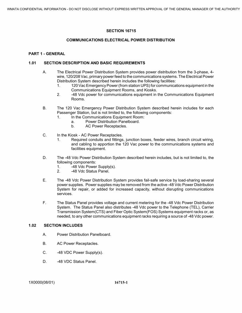
16715-11X0000(08/01)
SECTION 16715
COMMUNICATIONS ELECTRICAL POWER DISTRIBUTION
PART 1 - GENERAL
1.01 SECTION DESCRIPTION AND BASIC REQUIREMENTS
A. The Electrical Power Distribution System provides power distribution from the 3-phase, 4-wire, 120/208 Vac, primary power feed to the communications systems. The Electrical PowerDistribution System described herein includes the following facilities:1. 120 Vac Emergency Power (from station UPS) for communications equipment in the
Communications Equipment Rooms, and Kiosks.2. -48 Vdc power for communications equipment in the Communications Equipment
Rooms.
B. The 120 Vac Emergency Power Distribution System described herein includes for eachPassenger Station, but is not limited to, the following components:1. In the Communications Equipment Room:
a. Power Distribution Panelboard.b. AC Power Receptacles.
C. In the Kiosk - AC Power Receptacles.1. Required conduits and fittings, junction boxes, feeder wires, branch circuit wiring,
and cabling to apportion the 120 Vac power to the communications systems andfacilities equipment.
D. The -48 Vdc Power Distribution System described herein includes, but is not limited to, thefollowing components:1. -48 Vdc Power Supply(s).2. -48 Vdc Status Panel.
E. The -48 Vdc Power Distribution System provides fail-safe service by load-sharing severalpower supplies. Power supplies may be removed from the active -48 Vdc Power DistributionSystem for repair, or added for increased capacity, without disrupting communicationsservices.
F. The Status Panel provides voltage and current metering for the -48 Vdc Power DistributionSystem. The Status Panel also distributes -48 Vdc power to the Telephone (TEL), CarrierTransmission System(CTS) and Fiber Optic System(FOS) Systems equipment racks or, asneeded, to any other communications equipment racks requiring a source of -48 Vdc power.
1.02 SECTION INCLUDES
A. Power Distribution Panelboard.
B. AC Power Receptacles.
C. -48 VDC Power Supply(s).
D. -48 VDC Status Panel.
WMATA CONFIDENTIAL INFORMATION - DO NOT DISCLOSE WITHOUT EXPRESS WRITTEN APPROVAL OF THE GENERAL MANAGER OF THE AUTHORITY

16715-2 1X0000(08/01)
1.03 UNIT PRICES
A. Unit Prices include all Required conduits and fittings, junction boxes, feeder wires, branchcircuit wiring, and cabling to apportion the 120 VAC power and –48VDC power to thecommunications systems and facilities and incidental items, not specifically mentioned, butrequired for complete and proper system operation.
1.04 RELATED SECTIONS
A. Section 16706 - Communications System Submittals & Services.
B. Section 16707 - Communications Systems Quality Assurance & Testing
C. Section 16710 - Communications Grounding.
D. Section 16721 -Communications Telephone System.
E. Section 16771 -Communications Carrier Transmission System.
F. Section 16776 -Communications Fiber Optics System.
G. Section 16851 -Communications Closed Circuit Television System.
1.05 REFERENCES
A. National Electrical Manufacturers Association (NEMA) Standard Publication 250-1997,Enclosures for Electrical Equipment (1000 Volts Maximum).
B. NEMA Standard AB-1, Molded Case Circuit Breakers and Molded Case Switches
C. National Electric Code (NEC).
D. Insulated Cable Engineers Association (ICEA) S-95-658/NEMA WC70, Nonshielded 0 - 2kVCables; ICEA S-96-659/NEMA WC71, Nonshielded 2001 - 5kV Cables; ICEA S-93-639/NEMA WC74, Shielded Power Cables 5 - 46 kV; ICEA S-94-649, Concentric NeutralCables Rated 5 - 46 kV; ICEA S-97-682, Utility Shielded Power Cable Rated 5 - 46 kV; ICEAS-105-692, 600V Single Layer Thermoset Insulated Utility Underground Distribution Cable;and ICEA S-81-570, Direct Burial, 600V, Ruggedized Insulation.
1.06 SYSTEM DESCRIPTION
A. Description: The Communication Electrical Power Distribution provides power distributionfrom the 3-phase, 4-wire, 120/208 VAC, primary power feed to the communications systems.
B. Capacity:1. The Power Distribution Panelboard shall be sized to provide separate power circuits
to each freestanding or wall-mounted equipment rack and cabinet, and any otherequipment requiring an ac circuit feed. The Panelboard shall also include at least20% unused (spare) circuit-breaker spaces.
WMATA CONFIDENTIAL INFORMATION - DO NOT DISCLOSE WITHOUT EXPRESS WRITTEN APPROVAL OF THE GENERAL MANAGER OF THE AUTHORITY

16715-31X0000(08/01)
2. The AC Power Disconnect Switch shall be rated to switch the calculated worst-caseac current load, plus 50% spare capacity.
3. The Communications Equipment -48 Vdc Power Supply shall be rated to provide thecalculated worst-case dc current load, plus 100% spare capacity.
4. The -48 VDC Power System Status Panel shall be chosen to be fully compatible withthe –48 Vdc Power Supply throughout its rated operating range.
C. The -48 VDC Power Distribution System provides fail-safe service by load-sharing two, ormore, power supplies. At least one power supply may be removed from the active -48 VDCPower Distribution System for repair, or added for increased capacity, without disruptingcommunications services.
D. The Status Panel provides voltage and current metering for the -48 VDC Power DistributionSystem. The Status Panel also distributes -48 VDC power to the Telephone System (TEL),Carrier Transmission System (CTS) and Fiber Optic System (FOS) Systems equipmentracks or, as needed, to any other communications equipment racks requiring a source of -48VDC power.
E. The GETS system includes an existing personal computer (PC) (located in the JacksonGraham Building) equipped with software to interrogate the Emergency Telephones andtelephone circuits to assure reliable emergency communications. The PC software alsoprovides for remote programming of the Emergency Telephones in the parking garages.
1.07 SUBMITTALS
A. Submit under provisions of Section 16706.
B. Shop Drawings: Indicate electrical characteristics and connection requirements, includingsystem wiring diagram.
C. Product Data: Provide showing electrical characteristics and connection requirements foreach component.
D. Manufacturer's Installation Instructions: Indicate application conditions and limitations of usestipulated by Product testing agency. Include instructions for storage, handling, protection,examination, preparation, installation, and starting of Product.
E. Calculate full load ac power requirements per branch circuit and shall configure eachpanelboard for an optimum phase load balance. Submit the calculations to the Engineer forapproval. The calculations shall indicate the full load ac power requirements for each itemof equipment connected to each branch circuit.
1.07 QUALIFICATIONS
A. Manufacturer: Company specializing in manufacturing the Products specified in this sectionwith minimum three years documented experience.
B. Supplier: Authorized distributor of specified manufacturer with minimum three yearsdocumented experience.
C. Installer: Service facilities within 50 miles of Project.
WMATA CONFIDENTIAL INFORMATION - DO NOT DISCLOSE WITHOUT EXPRESS WRITTEN APPROVAL OF THE GENERAL MANAGER OF THE AUTHORITY

16715-4 1X0000(08/01)
1.08 MAINTENANCE SERVICE
A. Furnish service and maintenance of Electrical Power Distribution System until FinalCompletion.
PART 2 - PRODUCTS
2.01 POWER DISTRIBUTION PANELBOARD
A. Manufacturers:1. Square D Co., Model No. NQOD424L100CU (or approved equal).
B. Type: NQOD, 3-phase, 4 wire, 120/208 Vac, main lugs only with isolated solid neutral busand a ground bus.
C. Enclosure: NEMA Type 12 surface mounting and surface screw front cover with hinged doorand flush lock.
D. Minimum Ratings:1. Capacity: 20 single-pole branch circuit breakers.2. Panel Amperage: 750,000.3. Power Requirements: Main Lugs, 100 Amps.4. Minimum Circuit Breakers: 16 single-pole NEMA Standard AB-1.
2.02 TERMINAL SUPERVISOR’S AC POWER DISCONNECT SWITCH
A. Manufacturers:1. Square D Co., Model No. H221NAWK, (or approved equal).
B. Minimum Ratings:1. Type: NEMA Type 12 surface mounting and surface screw front cover with hinged
door and flush lock.2. Amperage Rating: 30 Amps.
2.03 10 - OUTLET AC POWER RECEPTACLE
A. Manufacturers:1. Wiremold Company, Multi-outlet System/Plugmold 2000, Series GB, Model No.
20GB506, (or approved equal).
B. Minimum Ratings:1. Pre-wired receptacles on 6-inch centers.2. 3-wire circuit, insulated ground conductor.3. Receptacles grounded to raceway.
2.04 6-OUTLET AC POWER RECEPTACLE
A. Manufacturers:1. Wiremold Company, Multi-outlet System/Plugmold 2000, Series GB, Model No.
20GB306, (or approved equal).
B. Minimum Ratings:
WMATA CONFIDENTIAL INFORMATION - DO NOT DISCLOSE WITHOUT EXPRESS WRITTEN APPROVAL OF THE GENERAL MANAGER OF THE AUTHORITY

16715-51X0000(08/01)
1. Pre-wired receptacles on 6-inch centers.2. 3-wire circuit, insulated ground conductor.3. Receptacles grounded to raceway.
2.05 DUPLEX AC POWER RECEPTACLE
A. Manufacturers:1. Arrow Hart Division, Cooper Industries, Model No. IG5362 with Model No. IG8248
wall plate, (or approved equal).
B. Minimum Ratings:1. Rated for 20 Amps, 125 VAC.2. Isolated ground receptacle.3. Color: Orange.
2.06 WIRE
A. Manufacturers:1. Triangle PWC, Inc., Everene, Model No. USE/RHW, (or approved equal).
B. Minimum Ratings:1. Insulation Type: Cross-linked Polyethylene in accordance with ICEA S-95-
658/NEMA WC70, ICEA S-96-659/NEMA WC71, ICEA S-93-639/NEMA WC74,ICEA S-94-649, ICEA S-97-682, ICEA S-105-692, and ICEA S-81-570.
2. Conductor: 12 AWG or larger Class B stranded copper.3. Voltage Rating: 600 volts.
2.07 GROUND CLAMP
A. Manufacturers:1. Wiremold Company, Multi-outlet System/Plugmold 2000, Model No. 2009, (or
approved equal).
B. Ratings:1. Compatible with Plugmold 2000.2. For use on multi-outlet systems.3. Plated.
2.08 COMMUNICATIONS EQUIPMENT -48 VDC POWER SUPPLY
A. Manufacturers:1. Power Conversion Products, Model No. PS-19 shelf complete with PCP Model No.
MOD-4812 rectifier modules (quantity of 2 per shelf), (or approved equal).
B. Minimum Ratings:1. Input: 95-130 VAC, 60-Hz (nominal), Power Factor: PF>90%.2. Output: -48 VDC, 24-amp (load sharing).3. Alarms: Rectifier Output Failure indicator with Form "C" alarm contacts.4. High dc voltage shutdown.5. Mounting: 19-inch rack complete with 23-inch rack mount adapters and hardware.
2.09 -48 VDC POWER SYSTEM STATUS PANEL
WMATA CONFIDENTIAL INFORMATION - DO NOT DISCLOSE WITHOUT EXPRESS WRITTEN APPROVAL OF THE GENERAL MANAGER OF THE AUTHORITY
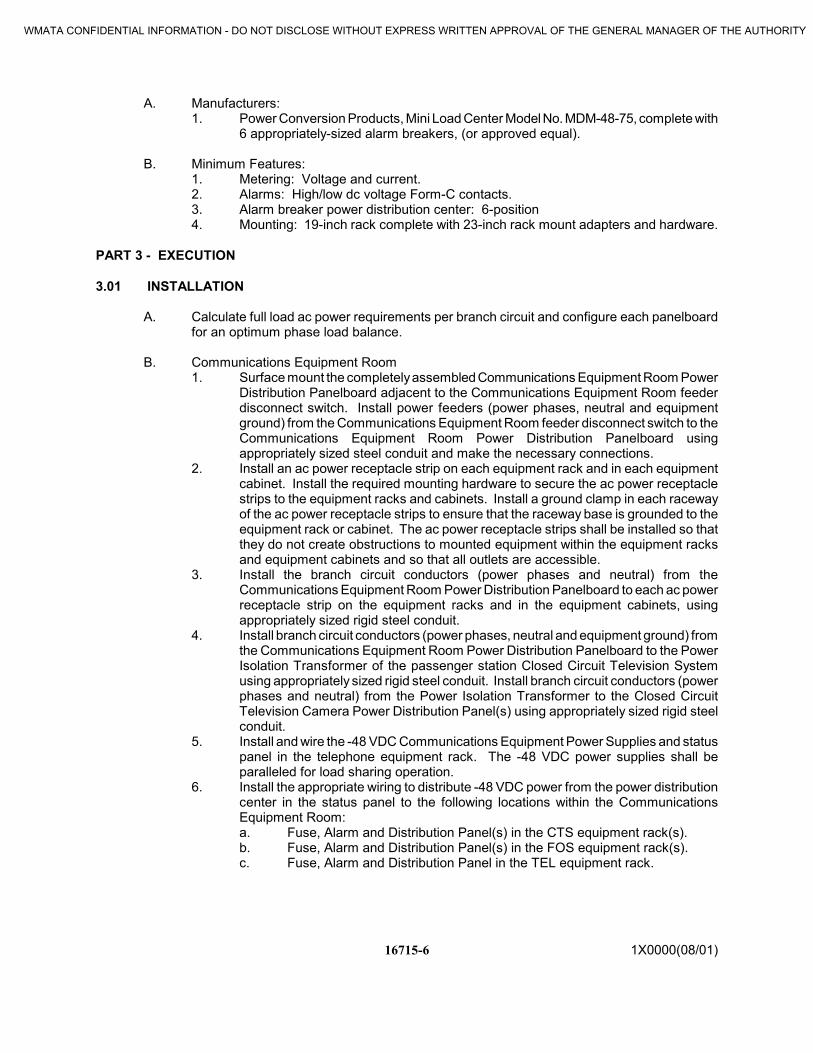
16715-6 1X0000(08/01)
A. Manufacturers:1. Power Conversion Products, Mini Load Center Model No. MDM-48-75, complete with
6 appropriately-sized alarm breakers, (or approved equal).
B. Minimum Features:1. Metering: Voltage and current.2. Alarms: High/low dc voltage Form-C contacts.3. Alarm breaker power distribution center: 6-position4. Mounting: 19-inch rack complete with 23-inch rack mount adapters and hardware.
PART 3 - EXECUTION
3.01 INSTALLATION
A. Calculate full load ac power requirements per branch circuit and configure each panelboardfor an optimum phase load balance.
B. Communications Equipment Room1. Surface mount the completely assembled Communications Equipment Room Power
Distribution Panelboard adjacent to the Communications Equipment Room feederdisconnect switch. Install power feeders (power phases, neutral and equipmentground) from the Communications Equipment Room feeder disconnect switch to theCommunications Equipment Room Power Distribution Panelboard usingappropriately sized steel conduit and make the necessary connections.
2. Install an ac power receptacle strip on each equipment rack and in each equipmentcabinet. Install the required mounting hardware to secure the ac power receptaclestrips to the equipment racks and cabinets. Install a ground clamp in each racewayof the ac power receptacle strips to ensure that the raceway base is grounded to theequipment rack or cabinet. The ac power receptacle strips shall be installed so thatthey do not create obstructions to mounted equipment within the equipment racksand equipment cabinets and so that all outlets are accessible.
3. Install the branch circuit conductors (power phases and neutral) from theCommunications Equipment Room Power Distribution Panelboard to each ac powerreceptacle strip on the equipment racks and in the equipment cabinets, usingappropriately sized rigid steel conduit.
4. Install branch circuit conductors (power phases, neutral and equipment ground) fromthe Communications Equipment Room Power Distribution Panelboard to the PowerIsolation Transformer of the passenger station Closed Circuit Television Systemusing appropriately sized rigid steel conduit. Install branch circuit conductors (powerphases and neutral) from the Power Isolation Transformer to the Closed CircuitTelevision Camera Power Distribution Panel(s) using appropriately sized rigid steelconduit.
5. Install and wire the -48 VDC Communications Equipment Power Supplies and statuspanel in the telephone equipment rack. The -48 VDC power supplies shall beparalleled for load sharing operation.
6. Install the appropriate wiring to distribute -48 VDC power from the power distributioncenter in the status panel to the following locations within the CommunicationsEquipment Room:a. Fuse, Alarm and Distribution Panel(s) in the CTS equipment rack(s).b. Fuse, Alarm and Distribution Panel(s) in the FOS equipment rack(s).c. Fuse, Alarm and Distribution Panel in the TEL equipment rack.
WMATA CONFIDENTIAL INFORMATION - DO NOT DISCLOSE WITHOUT EXPRESS WRITTEN APPROVAL OF THE GENERAL MANAGER OF THE AUTHORITY

16715-71X0000(08/01)
C. Kiosk1. Install the duplex receptacles, associated enclosures and cover plates within the
Kiosk cabinetry of the passenger station Kiosk. Install the required mountingbrackets and hardware to secure the enclosures of the duplex receptacles to theKiosk structure and/or Kiosk cabinetry. The duplex receptacles shall be installed sothat they do not create obstructions to mounted equipment within the Kiosk cabinetryand so that all receptacles are accessible.
2. Install branch circuit conductors (power phases, neutral and equipment ground)using appropriately sized, flexible, metallic conduit from the Kiosk EmergencyPanelboard to the duplex receptacles within the Kiosk. Install the required conduitfittings, hardware, junction boxes, connectors and grounding hardware, and makethe necessary connections.
D. Dispatcher’s Room1. Surface mount the Dispatcher’s Facility ac power disconnect switch and panelboard
in the vicinity of the Dispatcher’s Facility. The Contractor shall install power feeders(power phases, neutral and equipment ground) from the CommunicationsEquipment Room feeder disconnect switch to the Dispatcher’s Facility ac powerdisconnect switch, and from the disconnect switch to the panelboard. Installappropriately sized rigid conduit, the required conduit fittings and hardware, andmake the necessary connections. The power feeders to the Dispatcher’s Facility acpower disconnect switch shall be connected to the Communications EquipmentRoom feeder disconnect switch at the input side.
2. Install branch circuit conductors (power phases and neutral) from the Dispatcher’sac power panelboard to the ac receptacles in the Dispatcher’s Facility usingappropriately sized rigid conduit. Install the required conduit fittings, hardware,junction boxes, terminals, connectors, grounding hardware, and make the necessaryconnections and cross-connections.
E. Grounding1. Electrically insulate all conduits from equipment racks and equipment cabinets;
power ground shall be separate and isolated from the communications ground.Conduit containing branch circuit conductors shall be insulated from the equipmentracks and cabinets by means of short lengths of non-conducting conduits.
2. Provide short lengths of flexible metallic conduit in the equipment cabinets and onthe equipment racks between the non-conducting conduit and the ac powerreceptacle strips. Each branch circuit shall contain a separate neutral conductor tothe Communications Equipment Room Power Distribution Panelboard.
3.02 MANUFACTURER'S FIELD SERVICES
A. Prepare and start systems under provisions of Section 16707.
B. Supervise final wiring connections and system adjustments.
3.03 ADJUSTING
A. Adjust operating Products and equipment to ensure smooth and unhindered operation.
3.04 DEMONSTRATION
WMATA CONFIDENTIAL INFORMATION - DO NOT DISCLOSE WITHOUT EXPRESS WRITTEN APPROVAL OF THE GENERAL MANAGER OF THE AUTHORITY

16715-8 1X0000(08/01)
A. Demonstrate operation and maintenance of Products to designated WMATA personnel twoweeks prior to date of Substantial Completion.
B. Demonstrate Project equipment by a qualified person who is knowledgeable about theProject.
C. Utilize operation and maintenance manuals as basis for instruction. Review contents ofmanual with designated WMATA personnel in detail to explain all aspects of operation andmaintenance.
D. Demonstrate start-up, operation, control, adjustment, trouble-shooting, servicing,maintenance, and shutdown of each item of equipment at equipment location.
E. Prepare and insert additional data in operations and maintenance manuals when need foradditional data becomes apparent during instruction.
F. Demonstrate system operation
G. Conduct walking tour of Project and briefly describe function, operation, and maintenance ofeach component.
END OF SECTION
WMATA CONFIDENTIAL INFORMATION - DO NOT DISCLOSE WITHOUT EXPRESS WRITTEN APPROVAL OF THE GENERAL MANAGER OF THE AUTHORITY

WMATA CONFIDENTIAL INFORMATION – DO NOT DISCLOSE WITHOUT EXPRESS WRITTEN APPROVAL OF THE GENERAL MANAGER OF THE AUTHORITY
16732 - 1 1X0000 (12/11)
SECTION 16732
FIRE ALARM, DETECTION AND NOTIFICATION SYSTEM
PART 1 – GENERAL
1.1 BACKGROUND INFORMATION
The Washington Metropolitan Area Transit Authority (Metro) was created by an interstate compact in 1967 to plan, develop, build, finance, and operate a balanced regional transportation system in the national capital area. The Authority began building its rail system in 1969, acquired four regional bus systems in 1973, and began operating the first phase of Metrorail in 1976. Today, Metrorail serves 86 stations and has 106 miles of track. Metrobus serves the nation's capital 24 hours a day, seven days a week with 1,500 buses. Metrorail and Metrobus serve a population of 3.4 million within a 1,500-square mile jurisdiction. Metro began its paratransit service, MetroAccess, in 1994; it provides about 1.5 million trips per year. In support of its operations, WMATA currently operates 8 rail yards, 10 bus garages, and more than 10 miscellaneous buildings/facilities.
1.2. CURRENT ENVIRONMENT
All Metro stations, the majority of bus garages, and certain WMATA facilities have been equipped with a fire, intrusion alarm system based on UTC EST3 notification devices and components. WMATA personnel modify and maintain the EST3 fire alarm system and are certified by the manufacturer to do so. In addition to WMATA personnel being certified on the EST 3 system, WMATA has an in-house training lab to continually train personnel on WMATA specific fire alarm system troubleshooting and maintenance. All WMATA protected premises report to two proprietary supervising station locations. The supervising station locations are located at the Jackson Graham Building and at the Carmen Turner Facility. WMATA personnel program the fire alarm systems using an Edwards System user interface System Definition Utility. Intrusion detection and access control are integrated into the fire alarm systems. Access control database programming is done through a Resource Profile Manager. Fire alarm and access control field devices are routinely relocated as needed by certified WMATA personnel throughout the WMATA facilities. WMATA wishes to preserve current administration maintenance procedures for the fire alarm system.
1.3 DESCRIPTION
A. The requirements of the Contract Documents, including the General and Supplementary General
Conditions and Division 1 - General Requirements shall apply to the work in this section.
B. New fire alarm equipment shall be compatible with the existing WMATA fire alarm equipment. New equipment shall be able to provide two-way command and control communication between an EST Fireworks head end and all protected premise fire alarm control panels and field devices.
C. At the time of bid, all exceptions taken to these Specifications, all variances from these Specification and all substitutions of operating capabilities or equipment called for in these Specification shall be listed in writing and forwarded to WMATA. Any such exception, variances or substitutions which were not listed at the time of bid and are identified in the submittal, shall be grounds for immediate disapproval without comment.

WMATA CONFIDENTIAL INFORMATION – DO NOT DISCLOSE WITHOUT EXPRESS WRITTEN APPROVAL OF THE GENERAL MANAGER OF THE AUTHORITY
1X0000 (12/11) 16732 - 2
D. WMATA retains rights to review the Contractor's system and component configuration and products selected, and to accept or not accept for reasons of specification compliance or noncompliance. The Contractor shall remain responsible for providing an acceptable design and final product that meets the intent of this specification. The Contractor shall remain responsible for bearing any additional costs associated with changes necessary to satisfy the performance requirements of this specification.
E. The entire system shall be installed with aesthetics in mind. All control panels and remote annunciators installed in public spaces shall be semi-flush mounted with no exposed conduit or cable trays unless approved by WMATA.
F. Training materials, maintenance manuals and technician training shall be provided in compliance with these provisions. Provide all training, including all associated costs, to certify WMATA personnel to modify and maintain any proposed new non-EST fire alarm equipment. Number of WMATA personnel to be certified shall be determined by WMATA, based upon the scope of the project. Provide current version software keys to WMATA to modify and maintain the fire alarm system after training.
G. New and updated printed As-Built Drawing pages and CAD files shall be provided to reflect any changes made. As-Built Drawings shall be provided in both printed and electronic format. The contractor shall update the Data Files to reflect any changes.
1.4 WORK INCLUDED
A. The work covered by this Section of the Specification shall include all labor, equipment, materials and services to furnish and install a complete fire alarm system. It shall be complete with all necessary hardware, software and memory specifically tailored for this installation. It shall be possible to permanently modify the software on site by using a plug-in programmer. The system shall consist of, but not be limited to, the following:
1. Fire Alarm Control Panel and related remote data gathering panels. 2. Remote Annunciators with semi flush back box. 3. Conventional manual pull stations. 4. Conventional analog area smoke detectors. 5. Conventional analog duct smoke detectors. 6. Conventional analog heat detectors 7. Addressable manual pull stations. 8. Addressable analog area smoke detectors. 9. Addressable analog duct smoke detectors. 10. Addressable analog heat detectors. 11. Magnetic door/card access release override control. 12. Audible notification appliances - horns. 13. Audible notification appliances - speakers. 14. Visual notification appliances - strobes. 15. Proprietary supervising station alarm connection control. 16. Air handling systems shutdown control. 17. Magnetic door holder release. 18. Dry pipe sprinkler valve/deluge valve alarm and supervision. 19. Pre-Action Sprinkler System alarm and supervision. 20. Sprinkler supervisory switches and tamper switch supervision. 21. Battery standby. 22. Kitchen Hood Suppression System Monitoring. 23. Clean Agent and Halon System Monitoring.
1.5 RELATED SECTIONS
A. Section 08331 - Overhead Coiling Doors
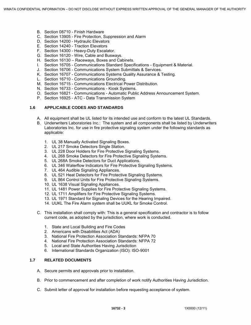
WMATA CONFIDENTIAL INFORMATION – DO NOT DISCLOSE WITHOUT EXPRESS WRITTEN APPROVAL OF THE GENERAL MANAGER OF THE AUTHORITY
16732 - 3 1X0000 (12/11)
B. Section 08710 - Finish Hardware C. Section 13905 - Fire Protection, Suppression and Alarm D. Section 14200 - Hydraulic Elevators E. Section 14240 - Traction Elevators F. Section 14300 - Heavy-Duty Escalator. G. Section 16120 - Wire, Cable and Busways. H. Section 16130 – Raceways, Boxes and Cabinets. I. Section 16705 - Communications Standard Specifications - Equipment & Material. J. Section 16706 - Communications System Submittals & Services. K. Section 16707 - Communications Systems Quality Assurance & Testing. L. Section 16710 - Communications Grounding. M. Section 16715 - Communications Electrical Power Distribution. N. Section 16733 - Communications - Kiosk Systems. O. Section 16821 - Communications - Automatic Public Address Announcement System. P. Section 16925 - ATC - Data Transmission System
1.6 APPLICABLE CODES AND STANDARDS
A. All equipment shall be UL listed for its intended use and conform to the latest UL Standards. B. Underwriters Laboratories Inc.: The system and all components shall be listed by Underwriters
Laboratories Inc. for use in fire protective signaling system under the following standards as applicable: 1. UL 38 Manually Activated Signaling Boxes. 2. UL 217 Smoke Detectors Single Station. 3. UL 228 Door Holders for Fire Protective Signaling Systems. 4. UL 268 Smoke Detectors for Fire Protective Signaling Systems. 5. UL 268A Smoke Detectors for Duct Applications. 6. UL 346 Waterflow Indicators for Fire Protective Signaling Systems. 7. UL 464 Audible Signaling Appliances. 8. UL 521 Heat Detectors for Fire Protective Signaling Systems. 9. UL 864 Control Units for Fire Protective Signaling Systems. 10. UL 1638 Visual Signaling Appliances. 11. UL 1481 Power Supplies for Fire Protective Signaling Systems. 12. UL 1711 Amplifiers for Fire Protective Signaling Systems. 13. UL 1971 Standard for Signaling Devices for the Hearing Impaired. 14. UUKL The Fire Alarm system shall be UUKL for Smoke Control.
C. This installation shall comply with: This is a general specification and contractor is to follow
current code, as adopted by the jurisdiction, where work is conducted. 1. State and Local Building and Fire Codes 2. Americans with Disabilities Act (ADA) 3. National Fire Protection Association Standards: NFPA 70 4. National Fire Protection Association Standards: NFPA 72 5. Local and State Authorities Having Jurisdiction 6. International Standards Organization (ISO): ISO-9001
1.7 RELATED DOCUMENTS
A. Secure permits and approvals prior to installation.
B. Prior to commencement and after completion of work notify Authorities Having Jurisdiction.
C. Submit letter of approval for installation before requesting acceptance of system.

WMATA CONFIDENTIAL INFORMATION – DO NOT DISCLOSE WITHOUT EXPRESS WRITTEN APPROVAL OF THE GENERAL MANAGER OF THE AUTHORITY
1X0000 (12/11) 16732 - 4
1.8 RELATED WORK
A. The Contractor shall coordinate work in this Section with all related trades. Work and/or equipment provided in other Sections and related to the fire alarm system shall include, but not be limited to:
1. Sprinkler waterflow and supervisory switches shall be furnished and installed by the fire protection contractor, but wired and connected by the Contractor. Modification of existing sprinkler devices to accommodate monitoring by the new fire alarm system shall be the responsibility of the fire alarm system installing contractor.
2. Duct smoke detectors shall be furnished, wired and connected by the Contractor. The HVAC contractor shall furnish necessary duct opening to install the duct smoke detectors.
3. Air handling and smoke exhaust system fan control circuits and status contacts to be furnished by the HVAC control equipment Contractor.
4. Elevator recall control circuits to be provided with the elevator control equipment. Modifications to the existing elevator controls to accommodate ANSI A17.1 shunt trip activation shall be provided by the elevator controls contractor. Any shunt trip circuit breakers and related wiring required for ANSI A17.1 compliance shall be provided by the Contractor (see power riser for more details).
5. Elevator recall and shunt trip devices and sequence of operation shall meet state and local elevator requirements.
6. Dry pipe/deluge and preaction sprinkler system valve control circuits and supervision contacts shall be provided by the fire protection contractor.
7. Kitchen hood extinguishing systems status monitoring.
8. Fire pumps (manual, automatic and special service) status monitoring.
a. Pump failure (fail to start) indication b. Pump running indication c. Phase reversal indication
9. Emergency generator status monitoring
a. Running indication b. Fail to start indication
10. Conduit, Wire and Cables: See Specification Sections 16120 and 16130.
11. Provide materials and labor for FACP to be monitored by OCC facilities located at the
Carmen Turner, JBG and future SOC facilities.
a. Fiber optic patch panels and fiber or telephones lines shall be the responsibility of the Installing Contractor.
1.9 SUBMITTALS

WMATA CONFIDENTIAL INFORMATION – DO NOT DISCLOSE WITHOUT EXPRESS WRITTEN APPROVAL OF THE GENERAL MANAGER OF THE AUTHORITY
16732 - 5 1X0000 (12/11)
A. Provide a list of all types of equipment and components provided. This shall be incorporated as part of a Table of Contents, which will also indicate the manufacturer’s part number, the description of the part, and the part number of the manufacturer’s product datasheet on which the information can be found. As provided in Part 2 of this Section of the Specifications, include any and all exceptions, variances or substitutions listed at the time of bid. Any such exceptions, variances or substitutions that were not listed at the time of bid and are identified in the submittal, shall be grounds for immediate disapproval without comment.
B. Provide a Sequence of Operation matrix. The sequence of operation shall be building specific, and shall provide individual sequences for every type of alarm, supervisory, or trouble condition which may occur as part of normal or off-normal system use.
C. Provide manufacturer’s ORIGINAL printed product data, catalog cuts and description of any special installation procedures. Photocopied and/or illegible product data sheets shall not be acceptable. All product datasheets shall be highlighted or stamped with arrows to indicate the specific components being submitted for approval.
D. Provide manufacturer’s installation instruction manual for specified system.
E. Provide samples of various items when requested.
F. Provide copy of state License to perform such work.
G. Provide copies of NICET Level III Fire Alarm certifications for a minimum of two (2) technicians assigned to this project also responsible for FACP programming.
H. Provide shop drawings as follows:
1. Coversheet with project name, address and drawing index.
2. General notes drawing with peripheral device back-box size information, part numbers, device mounting height information, and the names, addresses, point of contact, and telephone numbers of all contract project team members.
3. Building specific device riser diagram, which individually depicts all control panels,
annunciators, addressable devices, and notification appliances. Shall include a specific, proposed point descriptor above each addressable device. Shall include a specific, discrete point address that shall correspond to addresses depicted on the device layout floor plans. Drawing shall provide wire specifications, and wire tags shown on all conductors depicted on the riser diagram. All circuits shall have designations that shall correspond with those require on the control panel and floor plan drawings. End-of-line resistors (and values) shall be depicted.
4. Control panel termination drawing(s). Shall depict internal component placement and all
internal and field termination points. Drawing shall provide a detail indicating where conduit penetrations shall be made, so as to avoid conflicts with internally mounted batteries. For each additional data gathering panel, a separate control panel drawing shall be provided, which clearly indicated the designation, service and location of the control enclosure. End-of-line resistors (and values) shall be depicted.
5. See section 3.4 DOCUMENTATION AND TRAINING for other documents relating to this
section. 6. Building specific device wiring diagram drawing(s) shall be provided which depict all system
components, and their respective field wiring termination points. Wire type, gauge, and jacket shall also be indicated. When an addressable module is used in multiple configurations for monitoring or controlling various types of equipment, different device typical diagrams shall be provided. End-of-line resistors (and values) shall be depicted.

WMATA CONFIDENTIAL INFORMATION – DO NOT DISCLOSE WITHOUT EXPRESS WRITTEN APPROVAL OF THE GENERAL MANAGER OF THE AUTHORITY
1X0000 (12/11) 16732 - 6
7. Device layout floor plans shall be created for every area served by the fire alarm system. Floor plans shall indicate accurate locations for all control and peripheral devices. Drawings shall be no less than 1/8-inch scale. All addressable devices shall be depicted with a discrete address that corresponds with that indicated on the Riser Diagram. All notification appliances shall also be provided with a circuit address that corresponds to that depicted on the Riser Diagram. If individual floors need to be segmented to accommodate the 1/8” scale requirements, KEY PLANS and BREAK-LINES shall be provided on the plans in an orderly and professional manner. End-of-line resistors (and values) shall be depicted.
8. Contained in the title block of each drawing shall be symbol legends with device counts, wire
tag legends, circuit schedules for all addressable and notification appliance circuits, the project name/address, and a drawing description which corresponds to that indicated in the drawing index on the coversheet drawing. A section of each drawing title block shall be reserved for revision numbers and notes. The initial submission shall be Revision 0, with Revision A, B, or C as project modifications require.
I. Battery calculations shall be provided on a per power supply/charger basis. These calculations
shall clearly indicated the quantity of devices, the device part numbers, the supervisory current draw, the alarm current draw, totals for all categories, and the calculated battery requirements (which reflect a 20% DEGRADE, for 24 Hour supervisory, 5 minute alarm operation). Battery calculations shall also reflect all control panel component, remote annunciator, and auxiliary relay current draws. Failure to provide these calculations shall be grounds for the complete rejection of the submittal package.
J. Table of contents, product data sheets, sequences of operation, battery calculations, installation
instructions, licenses, NICET certifications and 11” x 17” reduced shop drawings shall be provided by the fire alarm vendor as part of a single, spiral bound submittal book. The submittal book shall have laminated covers indicating the project address, SED number, system type, and contractor. The book shall consist of labeled dividers, and shall not exceed 9 ½” in width, and 11 ½” in height.
K. Scale drawing sets shall be submitted along with the submittal booklets. These drawings shall be
22” x 34” and of a sufficient resolution to be completely legible when reduced to 11” x 17” size.
PART II - PRODUCTS
2.1 ACCEPTABLE MANUFACTURERS
A. Manufacturers capable of meeting the system requirements of Part II of this specification.
2.2 CIRCUITING GUIDELINES
A. Each addressable or conventional analog loop shall be circuited so device loading is not to exceed 80% of loop capacity in order to leave space for future devices. The loop shall have Class B operation unless otherwise noted on drawings.
B. Where it is necessary to interface conventional initiating devices provide intelligent input modules to supervise Class B zone wiring.
C. Each of the following types of devices or equipment shall be provided with supervised circuits as shown on the drawings but shall be typically designed as follows:
1. Sprinkler Valve Supervisory Switches: Provide one (1) supervisory module circuit for each sprinkler valve supervisory switch.

WMATA CONFIDENTIAL INFORMATION – DO NOT DISCLOSE WITHOUT EXPRESS WRITTEN APPROVAL OF THE GENERAL MANAGER OF THE AUTHORITY
16732 - 7 1X0000 (12/11)
2. When water flow and tamper switches exist at the same location, provide one (1) dual input addressable module.
3. When odd numbers of devices exist at a single location, provide additional single input
addressable module.
D. Each of the following types of alarm notification appliances shall be circuited as follows:
1. Audible Signals: Provide sufficient spare capacity to assure that an increase of 20% of the audible devices can be supported without the need for additional components (power supplies, signal circuit modules, batteries, etc.)
2. Visual Signals: Provide sufficient spare capacity to assure that an increase of 20% of the
visual devices can be supported without the need for additional components (power supplies, signal circuit modules, batteries, etc.)
E. Each of the following types of remote equipment associated with the fire alarm system shall be
provided with a form ‘C’ control relay contact as shown on the drawings, but shall be typically as follows:
1. HVAC Fan Systems: Provide one (1) shutdown control relay contact for each HVAC fan
system. 2. HVAC Supply Fans: Provide one (1) shutdown control relay contact for each HVAC supply
fan.
3. HVAC Return Fans: Provide one (1) shutdown control relay contact for each HVAC return fan.
F. Provide a dedicated 24VDC circuit to feed all auxiliary relays required for inductive loads. Circuits
shall be supervised via an end-of-line relay and addressable input module. Auxiliary relays shall not derive their power from the starter or load being controlled.
G. Each control or data gathering panel shall have a dedicated 20 Amp, 120 VAC feed. This feed
shall come from an emergency circuit breaker panel where available, and shall have a locked circuit breaker. Earth grounds shall also terminate to the same circuit breaker panel from each respective control panel.
2.3 FIRE ALARM SYSTEM SEQUENCE OF OPERATION
A. The system shall identify any off normal condition and log each condition into the system database as an event.
1. The system shall automatically display on the control panel Liquid Crystal Display the first event of the highest priority by type. The priorities and types shall be alarm, supervisory, trouble, and monitor.
2. The system shall have a Queue operation, and shall not require event acknowledgment by
the system operator. The system shall have a labeled color coded indicator for each type of event; alarm - red, supervisory - yellow, trouble - yellow, monitor - yellow. When an unseen event exists for a given type, the indicator shall be lit.
3. For each event, the display shall include the current time, the total number of events, the type
of event, the time the event occurred and up to a 42 character custom user description.
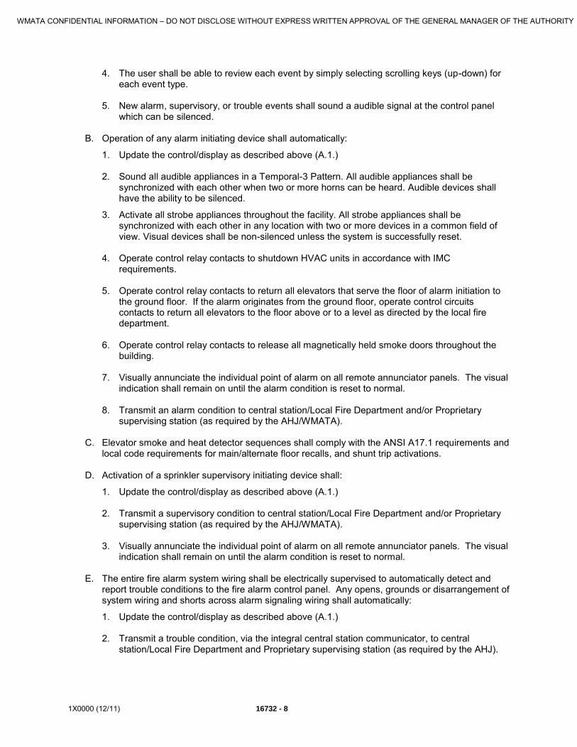
WMATA CONFIDENTIAL INFORMATION – DO NOT DISCLOSE WITHOUT EXPRESS WRITTEN APPROVAL OF THE GENERAL MANAGER OF THE AUTHORITY
1X0000 (12/11) 16732 - 8
4. The user shall be able to review each event by simply selecting scrolling keys (up-down) for each event type.
5. New alarm, supervisory, or trouble events shall sound a audible signal at the control panel
which can be silenced. B. Operation of any alarm initiating device shall automatically:
1. Update the control/display as described above (A.1.) 2. Sound all audible appliances in a Temporal-3 Pattern. All audible appliances shall be
synchronized with each other when two or more horns can be heard. Audible devices shall have the ability to be silenced.
3. Activate all strobe appliances throughout the facility. All strobe appliances shall be synchronized with each other in any location with two or more devices in a common field of view. Visual devices shall be non-silenced unless the system is successfully reset.
4. Operate control relay contacts to shutdown HVAC units in accordance with IMC
requirements. 5. Operate control relay contacts to return all elevators that serve the floor of alarm initiation to
the ground floor. If the alarm originates from the ground floor, operate control circuits contacts to return all elevators to the floor above or to a level as directed by the local fire department.
6. Operate control relay contacts to release all magnetically held smoke doors throughout the
building. 7. Visually annunciate the individual point of alarm on all remote annunciator panels. The visual
indication shall remain on until the alarm condition is reset to normal.
8. Transmit an alarm condition to central station/Local Fire Department and/or Proprietary supervising station (as required by the AHJ/WMATA).
C. Elevator smoke and heat detector sequences shall comply with the ANSI A17.1 requirements and
local code requirements for main/alternate floor recalls, and shunt trip activations.
D. Activation of a sprinkler supervisory initiating device shall:
1. Update the control/display as described above (A.1.) 2. Transmit a supervisory condition to central station/Local Fire Department and/or Proprietary
supervising station (as required by the AHJ/WMATA). 3. Visually annunciate the individual point of alarm on all remote annunciator panels. The visual
indication shall remain on until the alarm condition is reset to normal. E. The entire fire alarm system wiring shall be electrically supervised to automatically detect and
report trouble conditions to the fire alarm control panel. Any opens, grounds or disarrangement of system wiring and shorts across alarm signaling wiring shall automatically:
1. Update the control/display as described above (A.1.) 2. Transmit a trouble condition, via the integral central station communicator, to central
station/Local Fire Department and Proprietary supervising station (as required by the AHJ).

WMATA CONFIDENTIAL INFORMATION – DO NOT DISCLOSE WITHOUT EXPRESS WRITTEN APPROVAL OF THE GENERAL MANAGER OF THE AUTHORITY
16732 - 9 1X0000 (12/11)
3. Visually and audibly annunciate a general trouble condition, on the remote annunciator panels. The visual indication shall remain on until the trouble condition is repaired.
F. Purge / Smoke Control
1. Smoke control panels shall be UUKL listed specifically for smoke control operation to allow the smoke purge control to be housed in the FACP cabinet. The smoke control switches shall be located behind a locked glass door.
2. Where required, each floor shall have a dedicated switch for fan shutdown via a listed addressable control module. Each damper shall also be monitored at the panel for open/close position via control module. This module shall illuminate the associated Green LED when the damper is open and the Red LED when the damper is closed. The dampers shall be interlocked with the fans to prevent the Fan from activating while damper is closed.
G. The fire alarm and detection system provides controls to and/or interfaces with the following
systems and equipment:
1. Ventilation Fans 2. Fire Sprinkler Systems 3. Fare Gates 4. Elevators and Escalators 5. Data Transmission System (DTS) 6. Automatic Public Address Announcement System (APAAS) 7. Automatic Fare Collection (AFC) 8. Automatic Public Address 9. Fire Standpipe Systems 10. Clean Agent Systems 11. Combustible Gas Detection 12. Carbon Monoxide Detection
2.4 SUPPORT FOR INSTALLER AND WMATA MAINTENANCE
A. Provide a coded one-man walk test feature. Allow audible or silent testing. Signal alarms and
troubles during test. Allow receipt of alarms and programmed operations for alarms from areas not under test.
B. Provide internal system diagnostics and maintenance user interface controls to display/report the power, communication, and general status of specific panel components, detectors, and modules.
C. Provide loop controller diagnostics to identify common alarm, trouble, ground fault, Class A fault, and map faults. Map faults include wire changes, device type changes by location, device additions/deletions and conventional open, short, and ground conditions. Ground faults on the circuit wiring of remote module shall be identified by device address.
D. Allow the user to display/report the condition of addressable analog detectors. Include device address, device type, percent obscuration, and maintenance indicator. The maintenance indicator shall provide the user with a measure of contamination of a device upon which cleaning decisions can confidently be made.
E. Allow the user to report history for alarm, supervisory, monitor, trouble, smoke verification, watchdog, and restore activity. Include Facility Name, Licensee, Project Program Compilation date, Compiler Version, Project Revision Number, and the time and date of the History Report.
F. Allow the user to disable/enable devices, zones, actions, timers and sequences. Protect the disable function with a password.

WMATA CONFIDENTIAL INFORMATION – DO NOT DISCLOSE WITHOUT EXPRESS WRITTEN APPROVAL OF THE GENERAL MANAGER OF THE AUTHORITY
1X0000 (12/11) 16732 - 10
G. Allow the user to activate/restore outputs, actions, sequences, and simulate detector smoke levels.
H. Allow the service user to enter time and date, reconfigure an external port for download programming, initiate auto programming and change passwords. Protect these functions with a password.
I. WMATA shall retain complete rights and ownership to all software running in the system. The fire alarm equipment vendor shall provide useable hard and soft copies of the software database to WMATA at the end of the warranty period. The database provided shall be useable by any authorized and certified distributor of the product line, and shall include all applicable passwords necessary for total and unrestricted use and modification of the database.
2.5 UL LISTED AND APPROVED EQUIPMENT
A. Fire Alarm Control Panel Requirements: The fire alarm control panel or panels and all system devices (horn-strobes, strobes, pull stations,
smoke and heat detectors, etc. shall be compatible. All listed under one label “UL listed and approved” for the use of fire alarm systems in this area of the United States of America. The operating controls shall be located behind locked door with viewing window. All control modules shall be labeled, and all zone locations shall be identified.
Conventional fire alarm control panels: Conventional fire alarm control panel supporting 1/3/5/10 initiating device circuits and 1 - 4 notification appliance class B circuits as required in the space. If the panel is not a slave provide off premise communication DACT.
B. System Controllers
The main controller shall be supervised, site programmable, and of modular design supporting at least 125 detectors and 125 remote modules per addressable Signaling line Circuit (SLC). The controller shall support up to 10 SLC's per panel for a total system capacity of 2500 Intelligent Addressable points. The system shall be designed with peer-to-peer networking capability for enhanced survivability, with support for up to 64 nodes, each with up to 2500 points and an overall capacity of 160,000 points. The cabinets shall be steel, with a red finish.
C. The system shall store all basic system functionality and job specific data in non-volatile memory. All site specific and operating data shall survive a complete power failure intact. Passwords shall protect any changes to system operations.
D. The main controller module shall control and monitor all local or remote peripherals. It shall support at least a large 960 character LCD, power supply, remote LCD and zone display annunciators, printers, and support standard communication interface protocol devices such as color computer annunciators and color graphic displays. If configured as a network, each system shall display each and every point in the system and shall also support up to 64 remote LCD display annunciators. Remote LCD annunciators shall also display each and every point in the system and be sized with the same number of characters as in the main FACP display.
E. The panel shall have a means for proprietary supervising station remote site monitoring to include the following as required:
1. The panel shall have a digital alarm communicator transmitter (DACT) module to transmit alarm, supervisory and trouble signals to a Central Monitoring or Proprietary Supervising Station. The DACT shall support dual telephones lines, Contact I.D. communications, and configured for dual tone multi-frequency (DTMF) or pulse modes. It shall be possible to delay AC power failure reports, auto test call, and be site programmable. The dialer shall be capable of transmitting every individual alarm condition to the central station or proprietary supervising station.

WMATA CONFIDENTIAL INFORMATION – DO NOT DISCLOSE WITHOUT EXPRESS WRITTEN APPROVAL OF THE GENERAL MANAGER OF THE AUTHORITY
16732 - 11 1X0000 (12/11)
2. The network communications card shall be provided for each building to allow building to building, peer to peer networking.
3. Fiber optics communications interface shall be provided for buildings, where available, to allow building to building networking in a Class A configuration.
F. The system shall have built-in automatic system programming to automatically address and map all system devices attached to the main controller. A minimum default single stage alarm system operation shall be supported with alarm silence, event silence, drill, lamp test, and reset common controls.
G. Advanced Windows-based System Definition Utility with Program Version Reporting to document any and all changes made during system start-up or system commissioning shall be used to maintain site specific programming. Time and Date Stamps of all modifications made to the program must be included to allow full retention of all previous program version data. It shall support programming of any input point to any output point. The system shall support the use of Bar Code readers to assist custom programming functions. It shall allow authorized customization of fundamental system operations using initiating events to start actions, timers, sequences and logical algorithms. The system program shall meet the requirements of this project, current codes and standards, and satisfy the local Authority Having Jurisdiction.
H. The system shall support distributed processor intelligent detectors with the following operational attributes; integral multiple differential sensors, automatic device mapping, electronic addressing, environmental compensation, pre-alarm, dirty detector identification, automatic day/night sensitivity adjustment, normal/alarm LEDs, relay bases, sounder bases and isolator bases.
I. The system shall use full digital communications to supervise all addressable loop devices for placement, correct location, and operation. It shall allow swapping of “same type” devices without the need of addressing and impose the “location” parameters on replacement device. It shall initiate and maintain a trouble if a device is added to a loop and clear the trouble when the new device is mapped and defined into the system.
J. Each controller shall contain a communication card which contains two RS232 ports. A computer for programming locally and a printer shall be connected to the RS232 ports, a RS232 printer/programming port for programming locally via PC. When operational, each controller shall support a printer through the RS232 port and be capable of message routing.
K. System circuits shall be configured as follows: Addressable analog SLC loops Class B; Initiating Device Circuits Class B; Notification Appliance Circuits Class B; Network Communications Class A; Annunciator Communications Class A. NO TEE TAPS PERMITTED; Conventional SLC loops Class B; Initiating Device Circuits Class B; Notification Appliance Circuits Class B; NO TEE TAPS PERMITTED
L. Single stage operation shall be provided.
M. The system shall have a UL Listed Detector Sensitivity test feature, which will be a function of the smoke detectors and performed automatically every 4 hours.
N. The system shall support 100% of all remote devices in alarm and provide support for a 100% compliment of detector isolator bases.
O. All panel modules shall be supervised for placement and return trouble if damaged or removed.
P. The system shall have a CPU “watchdog” circuit to initiate trouble should the CPU fail.
Q. The system evacuation signal rate shall be temporal 3-3-3.
R. Audible notification appliances shall be affected by signal silence features. Visual signal appliance shall not be affected by signal silence features.

WMATA CONFIDENTIAL INFORMATION – DO NOT DISCLOSE WITHOUT EXPRESS WRITTEN APPROVAL OF THE GENERAL MANAGER OF THE AUTHORITY
1X0000 (12/11) 16732 - 12
S. User Interface The display module shall be of membrane style construction with a 24 line by 40-character (960
total characters) Liquid Crystal Display (LCD). The LCD shall use super-twist technology and backlighting for high contrast visual clarity and a colored gray/black and white display. In the normal mode the LCD shall display the time, a customer facility name, and the number of history events. In the alarm mode the LCD display the total number of events and the type of event on display. The LCD shall reserve 42 characters of display space for each user custom message by addressable device. The module shall have visual indicators for the following common control functions; Power, Alarm, Supervisory, Monitor, Trouble, Disable, Ground Fault, CPU fail, and Test. There shall be common control keys and visual indicators for reset, alarm silence, panel silence, and drill. Provide four pairs of display control keys for selection of event display by type (alarm, supervisory, monitor and trouble) and forward / backward scrolling through event listings. The operation of these keys shall be integrated with the related common control indicators to flash the indicators when un-displayed events are available for display and turn on steady when all events have been displayed. The LCD shall display the first event of the highest priority as well as the previous seven (7) alarm events “hands free” in chronological order so that the arriving firefighter may track the fires progression. Provide system function keys; status, reports, enables, disable, activate, restore, program, and test. The module shall have a numeric keypad, zero through nine with delete and enter keys. As an alternate if the above cannot be provided, provide UL-Listed 864 9th edition PC graphics display.
T. Power Supplies The power supply shall be a high efficiency switch mode type with line monitoring to automatically
switch to batteries for power failure or brown out conditions. The automatic battery charger shall have low battery discharge protection. The power supply shall provide internal power and 24 Vdc at 7.0A continuous for notification appliance circuits. The power supply shall be capable of providing 7A to output circuits for a maximum period of 100 milliseconds. All outputs shall be power limited. The battery shall be sized to support the system for 24 hours of supervisory and trouble signal current plus general alarm for 5 minutes.
U. Auxiliary power supplies shall be a high efficiency switch mode type with line monitoring to automatically switch to batteries for power failure or brown out conditions. The automatic battery charger shall have low battery discharge protection. The power supply shall provide internal power and 24 Vdc at 7.0A continuous for notification appliance circuits. The power supply shall be capable of providing 7A to output circuits for a maximum period of 100 ms. All outputs shall be power limited. The battery shall be sized to support the system for 24 hours of supervisory and trouble signal current plus general alarm for 5 minutes.
V. Network alpha-numeric annunciators shall be located throughout the facility as indicated on the plans. The system shall have the capacity to support 64 network annunciators or network panel nodes. Each annunciator shall contain a supervised; back lit liquid crystal with a minimum of 8 lines with 21 characters per line. Where required, the annunciator shall include additional zonal annunciation and manual control without additional enclosures.
W. The annunciator shall support full ability to serve as the operating interface to the system and shall include the following features;
1. Matched appearance with other system displays;
2. Each LCD Display on each node (cabinet) in the system shall be configurable to show the status of any or all of the following functions anywhere in the system:
a. Alarm b. Supervisory c. Trouble d. Monitor
X. It must be possible to have up to 64 network annunciators or panels on the network.

WMATA CONFIDENTIAL INFORMATION – DO NOT DISCLOSE WITHOUT EXPRESS WRITTEN APPROVAL OF THE GENERAL MANAGER OF THE AUTHORITY
16732 - 13 1X0000 (12/11)
Y. Each annunciator must be capable of supporting custom messages as well as system event annunciation. It must be possible to filter unwanted annunciation of trouble, alarm or supervisory functions on a by point or by geographic area.
Z. The graphic remote annunciators shall be mounted in stand-alone enclosures or integrated into the network panels. The annunciator graphical diagram shall be 1/16 inch per foot scale minimum and operating on nominal 24 Vdc. All annunciator switches shall be system input points and shall be capable of controlling any system output or function. The graphic annunciator shall be UL and ULC Listed. The graphic shall be back-lit using high intensity LEDs. The unit shall be semi-flush or surface mounted. The main graphic door shall be tamper resistant and equipped with a key lock. It shall be possible to update the graphic image in the field without replacing the entire graphic.
AA. The fire alarm panel shall provide integral security system interfaces.
2.6 COMPONENTS
A. Central Processing Unit Module — Provide a CPU with a RS 232 Communication Card and a RS 485B Network Communication Card.
B. Primary Power Supply — Provide a power supply with power input of 120 VAC, 3.0A, 50/60 Hz and power output of Internal DC 24 Vdc @ 7.0 A Max, Auxiliary DC Two 24 Vdc @ 3.5 Max. The battery charger shall be included in the power supply.
C. Main Liquid Crystal Display module — Provide a 3-LCD which can display eight (8) lines by 20 characters.
D. Modem Communicator - Provide a combination digital dialer/modem to communicate to industry standards digital dialer receivers for status reports.
E. Fiber Communicator – Provide a fiber communicator for networking control panels.
F. Intelligent Devices - General: Each remote device shall have a microprocessor with non-volatile memory to support its functionality and serviceability. Each device shall store as required for its functionality the following data: device serial number, device address, device type, personality code, date of manufacture, hours in use, time and date of last alarm, amount of environmental compensation left/used, last maintenance date, job/project number, current detector sensitivity values, diagnostic information (trouble codes) and algorithms required to process sensor data and perform communications with the loop controller. Each device shall be capable of electronic addressing, either automatically or application programmed assigned, to support physical/electrical mapping and supervision by location. Setting a device’s address by physical means shall not be necessary.
G. Intelligent Detectors — General: The System Intelligent Detectors shall be capable of full digital communications using both broadcast and polling protocol. Each detector shall be capable of performing independent fire detection algorithms. The fire detection algorithm shall measure sensor signal dimensions, time patterns and combine different fire parameters to increase reliability and distinguish real fire conditions from unwanted deceptive nuisance alarms. Signal patterns that are not typical of fires shall be eliminated by digital filters. Devices not capable of combining different fire parameters or employing digital filters shall not be acceptable. Each detector shall have an integral microprocessor capable of making alarm decisions based on fire parameter information stored in the detector head. Distributed intelligence shall improve response time by decreasing the data flow between detector and analog loop controller. Maximum total analog loop response time for detectors changing state shall be 0.5 seconds. Each detector shall have a separate means of displaying communication and alarm status. A green LED shall flash to confirm communication with the analog loop controller. A red LED shall flash to display alarm status. The detector shall be capable of identifying up to 32 diagnostic codes. This information shall be available for system maintenance. The diagnostic code shall be stored at the detector. Each smoke detector shall be capable of transmitting pre-alarm and alarm

WMATA CONFIDENTIAL INFORMATION – DO NOT DISCLOSE WITHOUT EXPRESS WRITTEN APPROVAL OF THE GENERAL MANAGER OF THE AUTHORITY
1X0000 (12/11) 16732 - 14
signals in addition to the normal, trouble and need cleaning information. It shall be possible to program control panel activity to each level. Each smoke detector may be individually programmed to operate at any one of five (5) sensitivity settings. Each detector microprocessor shall contain an environmental compensation algorithm that identifies and sets ambient “Environmental Thresholds” approximately six times an hour. The microprocessor shall continually monitor the environmental impact of temperature, humidity, other contaminates as well as detector aging. The process shall employ digital compensation to adapt the detector to both 24-hour long term and 4-hour short-term environmental changes. The microprocessor shall monitor the environmental compensation value and alert the system operator when the detector approaches 80% and 100% of the allowable environmental compensation value. Differential sensing algorithms shall maintain a constant differential between selected detector sensitivity and the “learned” base line sensitivity. The base line sensitivity information shall be updated and permanently stored at the detector approximately once every hour. The intelligent analog detectors shall be suitable for mounting on a variety of orientation/condition-specific detector mounting bases.
H. Fixed Temperature/Rate of Rise Heat Detector: Provide intelligent combination fixed temperature/rate-of-rise heat detectors. The heat detector shall have a low mass thermistor heat sensor and operate at a fixed temperature and at a temperature rate-of-rise. It shall continually monitor the temperature of the air in its surroundings to minimize thermal lag to the time required to process an alarm. The integral microprocessor shall determine if an alarm condition exists and initiate an alarm based on the analysis of the data. The intelligent heat detector shall have a nominal fixed temperature alarm point rating of 1350F and a rate-of-rise alarm point of 150F per minute. The heat detector shall be rated for ceiling installation at a minimum of 70 ft centers and be suitable for wall mount applications.
I. Photoelectric Smoke Detector: Provide intelligent photoelectric smoke detectors. The analog photoelectric detector shall utilize a light scattering type photoelectric smoke sensor to sense changes in air samples from its surroundings. The integral microprocessor shall dynamically examine values from the sensor and initiate an alarm based on the analysis of data. Systems using central intelligence for alarm decisions shall not be acceptable. The detector shall continually monitor any changes in sensitivity due to the environmental effects of dirt, smoke, temperature, aging and humidity. The information shall be stored in the integral processor and transferred to the analog loop controller for retrieval using a laptop PC or other equivalent program/service tool. The photo detector shall be rated for ceiling installation at a minimum of 30 ft centers and be suitable for wall mount applications. The photoelectric smoke detector shall be suitable for direct insertion into air ducts up to 3 ft high and 3 ft wide with air velocities up to 4,000 ft/min. without requiring specific duct detector housings or supply tubes. The percent smoke obscuration per foot alarm set point shall be field selectable to any of five sensitivity settings ranging from 1.0% to 3.5%. The photo detector shall be suitable for operation in the following environment: Temperature: 320F to 1200F, Humidity: 0-93% RH, non-condensing, Elevation: no limit.
J. Smoke Detector: Provide conventional smoke detectors where applicable. The two-wire photoelectric detector shall have the clean me feature to accommodate drift compensation. The detector shall be suitable for operation in the following environment: Temperature: 32°F to 120°F, Humidity: 0-93% RH, non-condensing. Coordinate with WMATA for additional heat detection and relay functions.
K. Multisensor Detector: Provide intelligent multisensor smoke detectors. The multisensor analog detector shall use a light scattering type photoelectric smoke sensor, a unipolar ionization smoke sensor and an ambient temperature sensor to sense changes in air samples from its surroundings. The integral microprocessor shall employ time based algorithms to dynamically examine values from the three sensors simultaneously and initiate an alarm based on that data. The multisensor detector shall be capable of adapting to ambient environmental conditions. The temperature sensor shall self-adjust to the ambient temperature of the surrounding air and input an alarm when there is a change of 650F in ambient temperature. Systems using central

WMATA CONFIDENTIAL INFORMATION – DO NOT DISCLOSE WITHOUT EXPRESS WRITTEN APPROVAL OF THE GENERAL MANAGER OF THE AUTHORITY
16732 - 15 1X0000 (12/11)
intelligence for alarm decisions shall not be acceptable. The detector shall continually monitor any changes in sensitivity due to the environmental effects of dirt, smoke, temperature, age and humidity. The information shall be stored in the integral processor and transferred to the analog loop controller for retrieval using a laptop PC. Separately mounted photoelectric detectors, ionization detectors and heat detectors in the same location are not acceptable alternatives. The Multisensor smoke detector shall be rated for ceiling installation at a minimum of 30 ft centers and suitable for wall mount applications.
L. Standard Detector Mounting Bases: Provide standard detector mounting bases suitable for mounting on North American 1-gang, 3½” or 4” octagon box and 4” square box. The base shall contain no electronics, support all detector types and have the following minimum requirements: Removal of the respective detector shall not affect communications with other detectors, Terminal connections shall be made on the room side of the base, bases that must be removed to gain access to the terminals shall not be acceptable. The base shall be capable of supporting one (1) remote alarm LED Indicator. Provide remote LED alarm indicators where shown on the plans.
M. Duct Detector Housing: Provide low profile intelligent addressable duct smoke detector as indicated on the project plans. Provide for variations in duct air velocity between 100 and 4,000 feet per minute and include a wide sensitivity range of .79 to 2.46%/ft. Obscuration. Include one shut down relay rated 2.0 amps @ 30 Vdc and also include slave high contact relays if required. Provide an air exhaust tube and an air sampling inlet tube that extends into the duct air stream up to ten feet. The addressable duct housing shall be suitable for extreme environments, including a temperature range of –20 to 158 degrees F and offer a harsh environment gasket option. Provide remote alarm LED Indicators and/or remote test station as indicated on the project plans.
N. Intelligent Modules — General: It shall be possible to address each module without the use of DIP or rotary switches. Devices using DIP switches for addressing shall not be acceptable. The personality of multifunction modules shall be programmable at site to suit conditions and may be changed at any time using a code downloaded from the Analog Loop Controller. Modules requiring EPROM, PROM, ROM changes or DIP switch and/or jumper changes shall not be acceptable. The modules shall have a minimum of 2 diagnostic LEDs mounted behind a finished cover plate. A green LED shall flash to confirm communication with the loop controller. A red LED shall flash to display alarm status. The module shall be capable of storing up to 24 diagnostic codes which can be retrieved for troubleshooting assistance. Input and output circuit wiring shall be supervised for open and ground faults. The module shall be suitable for operation in the following environment: Temperature: 32°F to 120°F, Humidity: 0-93% RH, non-condensing.
O. Single Input Module (Waterflow Detectors, Tamper Switches etc.): Provide intelligent single input modules. The Single Input Module shall provide one (1) supervised Class B input circuit capable of a minimum of 4 “personalities”, each with a distinct operation. The module shall be suitable for mounting on North American 2 ½”deep 1-gang boxes and 1 ½” (38mm) deep 4” square boxes with 1-gang covers. The single input module shall support the following circuit types: Normally-Open Alarm Latching (Manual Stations, Heat Detectors, etc.), Normally-Open Alarm Delayed Latching (Waterflow Switches), Normally-Open Active Non-Latching (Monitor, Fans, Dampers, Doors, etc.), Normally-Open Active Latching (Supervisory, Tamper Switches).
P. Dual Input Module: Provide intelligent dual input modules. The Dual Input Module shall provide two (2) supervised Class B input circuits each capable of a minimum of 4 “personalities”, each with a distinct operation. The module shall be suitable for mounting on North American 2 ½” deep 1-gang boxes and 1 ½” deep 4” square boxes with 1-gang covers. The dual input module shall support the following circuit types: Normally-Open Alarm Latching (Manual Stations, Heat Detectors, etc.), Normally-Open Alarm Delayed Latching (Waterflow Switches), Normally-Open Active Non-Latching (Monitor, Fans, Dampers, Doors, etc.), Normally-Open Active Latching (Supervisory, Tamper Switches).
Q. Monitor Module: Provide intelligent monitor modules. The Monitor Module shall be factory set to support one (1) supervised Class B Normally-Open Active Non-Latching Monitor circuit. The

WMATA CONFIDENTIAL INFORMATION – DO NOT DISCLOSE WITHOUT EXPRESS WRITTEN APPROVAL OF THE GENERAL MANAGER OF THE AUTHORITY
1X0000 (12/11) 16732 - 16
monitor module shall be suitable for mounting on North American 2 ½” deep 1-gang boxes and 1 ½” deep 4” square boxes with 1-gang covers.
R. Universal I/O module Motherboard – Provide motherboards that provide mounting and wire terminations for modules. The motherboard shall support up to six modules. Locations: Communication Equipment Room, and Ancillary locations.
S. Waterflow/Tamper Module: Provide intelligent waterflow/tamper modules. The Waterflow/Tamper Module shall be factory set to support two (2) supervised Class B input circuits. Channel A shall support a Normally-Open Alarm Delayed Latching Waterflow Switch circuit. Channel B shall support a Normally-Open Active Latching Tamper Switch. The waterflow/tamper module shall be suitable for mounting on North American 2 ½” deep 1-gang boxes and 1 ½” deep 4” square boxes with 1-gang covers.
T. Single Input Signal Module: Provide intelligent single input signal modules. The Single Input (Single Riser Select) Signal Module shall provide one (1) supervised Class B output circuit capable of a minimum of 2 “personalities”, each with a distinct operation. When selected as a telephone power selector, the module shall be capable of generating its own “ring tone”. The module shall be suitable for mounting on North American 2 ½” deep 2-gang boxes and 1 ½” deep 4” square boxes with 2-gang covers. The single input signal module shall support the following operations: Audible/Visible Signal Power Selector (Polarized 24 Vdc @ 2A).
U. Control Relay Module: Provide intelligent control relay modules. The Control Relay Module shall provide one form “R” dry relay contact rated at 2 amps @ 24 Vdc to control external appliances or equipment shutdown. The control relay shall be rated for pilot duty and releasing systems. The position of the relay contact shall be confirmed by the system firmware. The control relay module shall be suitable for mounting on North American 2 ½” deep 1-gang boxes and 1 ½” deep 4” square boxes with 1-gang covers.
V. Conventional Manual Pull Stations — General: It shall be double action model with single pole contact used for pre-signal or general alarm initiation. The model shall have terminals for field connection of wire. The manual stations shall be provided with a key lock matching the FACP. The manual pull station shall not be provided with a glass break operation. Surface mount the manual pull station unless flush mount is possible. The fire alarm pull station shall be suitable for operation in the following environment: Temperature: 32°F to 120°F, Humidity: 0-93% RH, non-condensing. Provide accessories as required for the installation.
W. Intelligent Manual Pull Stations — General: It shall be possible to address each fire alarm pull station without the use of DIP or rotary switches. Devices using DIP switches for addressing shall not be acceptable. The manual stations shall have a minimum of 2 diagnostic LEDs mounted on their integral, factory assembled single or two stage input module. A green LED shall flash to confirm communication with the loop controller. A red LED shall flash to display alarm status. The station shall be capable of storing up to 24 diagnostic codes that can be retrieved for troubleshooting assistance. Input circuit wiring shall be supervised for open and ground faults. The fire alarm pull station shall be suitable for operation in the following environment: Temperature: 32°F to 120°F, Humidity: 0-93% RH, non-condensing.
X. Manual Pull Station: Provide intelligent double action, single stage fire alarm stations. The fire alarm station shall be of metal construction with an internal toggle switch. Provide a locked test feature. Finish the station in red with silver “PULL IN CASE OF FIRE” English lettering. The manual station shall be suitable for mounting on North American 2 ½” deep 1-gang boxes and 1 ½” deep 4” square boxes with 1-gang covers.
Y. Notification Appliances – General: All appliances shall be UL Listed for Fire Protective Service. All strobe appliances or combination appliances with strobes shall be capable of providing the “Equivalent Facilitation” which is allowed under the Americans with Disabilities Act accessibly guidelines (ADA (AG)), and shall be UL 1971, and ULC S526 Listed. All appliances shall be of the same manufacturer as the Fire Alarm Control Panel (NO EXCEPTIONS) specified to insure absolute compatibility between the appliances and the control panels, and to insure that the

WMATA CONFIDENTIAL INFORMATION – DO NOT DISCLOSE WITHOUT EXPRESS WRITTEN APPROVAL OF THE GENERAL MANAGER OF THE AUTHORITY
16732 - 17 1X0000 (12/11)
application of the appliances are done in accordance with the single manufacturers’ instructions. Any appliances that do not meet the above requirements, and are submitted for use must show written proof of their compatibility for the purpose intended. Such proof shall be in the form of documentation from THE CONTROL PANEL MANUFACTURER clearly stating that the control equipment (as submitted) is 100% compatible with the submitted Notification Appliances.
Z. Strobes: Provide low profile wall mounted strobes at the locations shown on the drawings. Strobes shall provide synchronized flash outputs. Strobe output shall be field selectable as indicated on the drawings in one of the following intensity levels; 15/75, 15cd, 30cd, 75cd or 110cd*. Low profile strobes shall mount in a North American 1-gang box or surface mounted on a matching back box provided by the manufacturer, as directed in the field. Provide weatherproof type and associated components when strobe is located outside or in areas requiring weather proofing.
* The fire alarm vendor may select below 75 candela where allowed by the appropriate release of ADA. 15/75 strobes may be used in corridors and in locations where 15 candela is required per NFPA wall and ceiling tables (see NFPA 72).
AA. Temporal Horn/Strobes: Provide low profile wall mount horn/strobes at the locations shown on the drawings. The horn/strobe shall provide an audible output of 84.4 dBA at 10 ft at the high setting and for smaller room size locations (as indicated on the plans) a low dB setting (field selectable) of 79.4 dB at 10 ft. when measured in reverberation room per UL-464. Strobes shall provide synchronized flash outputs. The strobe output shall be as indicated on the drawings in one of the following field selectable intensity levels*; 15/75, 15cd, 30cd, 75cd & 110cd devices. The horn shall have a selectable steady or synchronized temporal output. Low profile horn/strobes shall mount in a North American 1-gang box or surface mounted on a matching back box provided by the manufacturer, as directed in the field.
* The fire alarm vendor may select below 75 candela where allowed by the appropriate release of ADA. 15/75 strobes may be used in corridors and in locations where 15 candela is required per NFPA wall and ceiling tables (see NFPA 72).
BB. Temporal Horn: Provide low profile wall mount horn at the locations shown on the drawings. The horn shall provide an audible output of 84.4 dBA at 10 ft at the high setting and for smaller room size locations (as indicated on the plans) a low dB setting (field selectable) of 79.4 dB at 10 ft. when measured in reverberation room per UL-464. The horn shall have a selectable steady or synchronized temporal output. Low profile horn shall mount in a North American 1-gang box or surface mounted on a matching back box provided by the manufacturer, as directed in the field.
CC. Speaker/Strobe: Provide low profile wall mount speaker/strobes at the locations shown on the drawings. The strobe output shall be as indicated on the drawings in one of the following field selectable intensity levels; 15cd, 30cd, 75cd & 110cd devices. Speakers shall operate between ¼ Watt and 2 Watts and shall provide an audible output between 80 dBA and 89 dBA.
DD. Speaker: Provide low profile wall mount speakers at the locations shown on the drawings. Speakers shall operate between ¼ Watt to 2 Watts and shall provide an audible output between 80 dBA and 89 dBA.
EE. Multi-Voltage Control Relays: Provide remote control relays connected to supervised ancillary circuits for control of fans, dampers, door releases, etc. Relay contact ratings shall be DPDT and rated for 10 amperes at 115 Vac. A single relay may be energized from a voltage source of 24 Vdc, 24 Vac, 115 Vac, or 230 Vac. A red LED shall indicate the relay is energized. A metal enclosure shall be provided.
FF. Electromagnetic Door holders – General: Electromagnetic door holders submitted for use must have written proof of their compatibility for the purposes intended. Such proof shall be in the form of documentation from all manufacturers that clearly states that their equipment (as submitted) is 100% compatible with each other for the purposes intended.
GG. Wall Mounted, 1504/1505/1508/1509 Series: Provide flush, semi-flush or surface wall mounted electromagnetic door holder/releases rated at 24 Vac/dc. Finish shall be brushed zinc.

WMATA CONFIDENTIAL INFORMATION – DO NOT DISCLOSE WITHOUT EXPRESS WRITTEN APPROVAL OF THE GENERAL MANAGER OF THE AUTHORITY
1X0000 (12/11) 16732 - 18
HH. Surge Suppressor: Surge suppressors shall be multi-stage, hardwired base, field replaceable, with multiple voltage settings. 2 pairs shall be protected per module. UL497B listed with 10AWG max screw terminals. 0-75 service voltage, 6.6-108V list through voltage.
II. Manual Pull Station Guards: Manual pull stations shall be provided with guards as required on the plans. They shall be surface or flush mounting, as required for each individual device.
JJ. Voice Evacuation - The audio system must provide simultaneous page, alert, and evacuation signals. Systems that cause signaling devices to go silent while performing signaling functions will not be acceptable. The system must provide operation to 25Vrms or 70.7Vrms speakers. The system must provide as a minimum the following paging common controls and indicators: Ready to page LED, VU display of paging output level, single switch function for paging to all — Alert zones, Evacuation zones, and areas not programmed for signaling. The system must provide high quality analog to digital conversion of paging sources. Digital transmission of paging must be provided between system nodes. The analog sources must be sampled and converted to digital with a sampling rate no less than 9600 samples per second. It must be possible to transmit signal sources (Alert, Alarm, Page, etc.) together over a single pair of wires between nodes. System amplifiers must be distributed zoned type. Centrally banked systems are not acceptable. An integral circuit for operating traditional NAC devices must be provided with each system amplifier. The circuit must carry a minimum rating of 3.5 Amps for operating 24 VDC signals. The system shall provide fully integrated fire fighters’ telephone system that shall provide 2-way communication between the fire alarm control panel and any fire fighters’ telephone station. The system shall include an alphanumeric user display and controls. When a telephone is activated, a call-in buzzer shall sound, and the location of the phone shall be shown on the alphanumeric display. The display shall be capable of bilingual operation, displaying English, Dutch, Finnish, French, German, Italian, Portuguese or Spanish messages. The incoming call shall be selected by activating a single button. All subsequent telephone call locations shall be displayed in full text. The system shall display all incoming calls, all connected phone(s) on the alphanumeric display. The system shall be configured so that page messages may be issued from any firefighter’s telephone connected to the system, as directed by the emergency operator.
PART III - EXECUTION
3.1 INSTALLATION
A. The entire system shall be installed in a workmanlike manner, in accordance with approved
manufacturer’s wiring diagram. The contractor shall furnish all conduit, wiring, outlet boxes, junction boxes, cabinets and similar devices necessary for the complete installation. All wiring shall be of the type recommended by the manufacturer, approved by the local Fire Department and specified herein.
B. All penetration of floor slabs and firewalls shall be sleeved (1” conduit minimum) fire stopped in accordance with all local fire codes.
C. End of Line Resistors shall be furnished as required for mounting as directed by the manufacturer. Devices containing end-of-line resistors shall be appropriately labeled. Devices should be labeled so removal of the device is not required to identify the EOL device.
D. All manual pull stations shall be mounted 48 inches above the finished floor, as measured to the handle.
E. Wall-mounted appliances shall be mounted such that the entire lens is not less than 80 in. and not greater than 96 in. above the finished floor. Where low ceiling heights do not permit mounting at a minimum of 80 in., appliances shall be mounted within 6 in. of the ceiling. All audiovisual devices shall have lexan covers in all areas.
F. No area smoke detectors shall be mounted within 36 inches of any HVAC supply, return air register or lighting fixture.

WMATA CONFIDENTIAL INFORMATION – DO NOT DISCLOSE WITHOUT EXPRESS WRITTEN APPROVAL OF THE GENERAL MANAGER OF THE AUTHORITY
16732 - 19 1X0000 (12/11)
G. No area smoke or heat detector shall be mounted within 12 inches of any wall. All detectors shall be installed in strict accordance with NFPA 72 guidelines for such devices.
H. All addressable modules shall be mounted within 36 inches of the monitored or controlled point of termination. This shall include, but is not necessarily limited to, fan shutdown, elevator recall, shunt trip, sprinkler status points, or door release. Label all addressable modules as to their function.
I. New door holders shall derive their 24VAC/VDC power from a separate power supply housed in a dedicated, metal enclosure. The power supply shall have a 120VAC feed, and is to be centrally located to serve door holders on a per floor or area basis. All existing door holders shall be connected to new FACP. E.C. shall extend all existing wiring in order to make this work.
J. All low voltage wiring terminated to the fire alarm system shall be plenum rated with no exceptions and no less than No. 18 AWG in size, and solid copper.
K. All line voltage (120VAC) wiring shall be no less than No. 12 AWG in size, and solid copper. This shall include all system grounding. FACP must have a dedicated 20 Amp circuit marked back at the power panel no exceptions.
L. All wiring shall be color-coded throughout, to National Electrical Code standards.
M. Power-limited/Non-power-limited NEC wiring standards shall be observed.
N. All junction box covers shall be painted federal safety red and labeled FIRE ALARM SYSTEM ONLY in black letters.
O. Fire alarm system wiring shall not co-mingle with any other system wiring in the facility. Conduits shall not be shared under any circumstance. Only when fire alarm wiring enters the enclosure of a monitored or controlled system will co-habitation be permitted (i.e. at fan starters or elevator controllers).
P. Fire alarm control panel enclosures shall have engraved labels indicating, “FIRE ALARM SYSTEM”, and the areas of the building served by that panel.
Q. Auxiliary relays shall be appropriately labeled to indicate “FIRE ALARM SYSTEM” and their specific function (i.e. FAN S-1 SHUTDOWN).
R. All fire alarm wiring shall be continuous and without splices. Terminations shall only occur at fire alarm devices or control panel enclosures under terminal screws. All other splicing methods are specifically disallowed (i.e. plastic wire nuts).
S. All fire alarm wiring shall be installed in conduit. See Specification Section 16120.
T. All fire alarm wiring shall be sleeved when passing through any wall, using conduit sleeves (1” min.) with bushings, and fire stopped in accordance with Code.
U. The fire alarm system shall be arranged to receive power from one three wire 120 Vac, 20 A supply. All low voltage operation shall be provided from the fire alarm control panel.
V. All fire alarm devices shall be accessible for periodic maintenance. Should a device location indicated on the Contract Drawings not meet this requirement, it shall be the responsibility of the installing contractor to bring it, in writing, to the attention of the WMATA. Failure to bring such issues to the attention of WMATA shall be the exclusive liability of the installing Contractor.
W. The existing fire alarm system shall remain in operation until such time that approval has been granted for its removal.
X. After acceptance of the new building fire alarm system, the installing Contractor shall be responsible for the removal of entire existing fire alarm system components and controls, upon approval of the AHJ and WMATA. WMATA reserves the right to retain any existing fire alarm system components, upon their request. All existing fire alarm system components requiring special handling for disposal (due to radioactivity) shall be the responsibility of the installing

WMATA CONFIDENTIAL INFORMATION – DO NOT DISCLOSE WITHOUT EXPRESS WRITTEN APPROVAL OF THE GENERAL MANAGER OF THE AUTHORITY
1X0000 (12/11) 16732 - 20
contractor. Written proof of proper disposal by the installing contractor shall be required prior to release of outstanding retainage.
3.2 FIELD QUALITY CONTROL
A. The system shall be installed and fully tested under the supervision of a trained manufacturer’s representative. The system shall be demonstrated to perform all of the function as specified.
B. The installing contractor or fire alarm equipment vendor shall have no less than two (2) NICET Level III fire alarm technicians dedicated to this project.
C. The Installing Contractor and the Fire Alarm System Vendor shall, upon the request of the Consulting Engineer or WMATA attend any and all project meetings for the purpose of accurately determining progress.
D. It shall be the responsibility of the installing contractor to assure that construction debris does not adversely affect any sensing devices installed as part of this project. Should it be deemed necessary by the WMATA construction manager, the installing contractor shall be responsible for the cleaning of all smoke detectors prior to final acceptance.
3.3 TESTS
A. The fire alarm system vendor shall test the system in accordance with the manufacturer’s requirements and NFPA 72. The vendor shall provide final acceptance test reports to WMATA for review and approval prior to final acceptance.
B. Each individual system operation on a circuit by circuit basis shall be tested for its complete operation in accordance with NFPA 72 (2010ed.), Table 14.4.2.2 (see appropriate section from other editions). The procedure for testing the entire fire alarm system shall be set forth with the consent of the code enforcement official, the Engineer and the manufacturer.
C. Provide a NFPA 72 Record of Completion Form for each part of the fire alarm system as required.
3.4 DOCUMENTATION AND TRAINING
A. The contractor shall compile and provide to WMATA a complete manual on the completed system to include site specific operating and maintenance instruction, catalog cuts of all equipment and components, as-built wiring diagrams and a manufacturer’s suggested spare parts list. An operational Video, on DVD media, shall also be included.
B. The Contractor shall provide the onsite services of a manufacturer’s trained representative for two (2) separate calendar days for a period of eight (8) hours per day to instruct the WMATA’s designated personnel on the operation and maintenance of the entire system.
C. Factory Training: The Contractor shall include the cost to provide the factory certification training referenced in section1.3, F of this specification. Costs associated with the training but not limited to shall include:
Airfare to training location and back to greater Washington D.C Area
Training class presented by manufacturer
Training materials
Certification testing
Lodging

WMATA CONFIDENTIAL INFORMATION – DO NOT DISCLOSE WITHOUT EXPRESS WRITTEN APPROVAL OF THE GENERAL MANAGER OF THE AUTHORITY
16732 - 21 1X0000 (12/11)
Car rental
Miscellaneous expenses
C. As-built drawings shall consist of the following:
1. Revise existing drawings to incorporate contract work.
2. Point-to-point depiction of all device wiring on the device layout floor plans.
3. Full size, as-built drawings.
4. All drawings should be readable and printable in 11 x 17.
5. Provide electronic copies in CAD and PDF.
6. Provide one copy inside PVC pipe next to FACP.
D. Turnover of all software database hard/soft copies to WMATA. This shall include all possible programming software logs, exported project files, hard copies of all device maps, the revision number of the version of programming utility used, and all required passwords. This information shall be provided to WMATA on a flash drive.
F. The turnover of all database information shall occur prior to the end of the One (1) warranty period (or period as amended earlier in this specification).
END OF SECTION

1X0000 (08/01) 16733 - 1
SECTION 16733
COMMUNICATIONS - KIOSK SYSTEMS
PART 1 GENERAL
1.01 SECTION DESCRIPTION AND BASIC REQUIREMENTS
A. The purpose of the Kiosk System is to provide the kiosk with the equipment needed tomonitor and control passenger station Communications Systems, Fire and Intrusion AlarmSystems, to provide data signals to fare collection equipment, elevators and escalators, andto provide an effective communications interface with the public (customers).
B. At least one kiosk is located in each passenger station of the Washington Metropolitan AreaTransit Authority (WMATA) Rail Rapid Transit System. It is the focal point of activity at eachpassenger station. At large passenger stations, each operational level may contain morethan one kiosk. Where more than one kiosk is located on a single level, one kiosk isdesignated as the "Major Kiosk." All other kiosks are designated "Minor Kiosks." In thosestations where a single kiosk exists, it is considered to be the "Major Kiosk."
C. Facilities are to be provided in each kiosk for the station manager to monitor and controlpassenger station systems. The contractor shall provide a complete "Kiosk Facility" whichshall include kiosk cabinets, system interface panels, cables, cable termination facilities,loudspeakers, wiring and all hardware needed to complete the installation of StationMonitor/Control Systems in the kiosk. The requirements for the individual monitor/controlpanels and systems, to be installed in the kiosk under this contract, are included in therespective System Specification Sections.
D. The contractor shall provide Cabinet Bays #1 through #6 in the Kiosk(s) included in thiscontract, as indicated on the contract drawings. Kiosk Cabinet Bay #7 will be furnished andinstalled by other trades.
E. The contractor shall provide a Cable Termination Rack in Cabinet Bay # 3 of the kiosk(s)covered by this contract. The kiosk Cable Termination Rack shall consist of seven TerminalStrips and a Line Terminal Block. Terminal Strips shall be equally spaced on theTermination Rack. Each Terminal Strip within the kiosk Cable Termination Rack shallconsist of sixty (60) individual terminals. The kiosk Cable Termination Rack shall beprovided in the kiosk(s) to terminate all cables and wires that are to be installed into thekiosk(s) under this contract, with the following exceptions: 1. Coaxial video cables.2. Automatic Public Address Announcement System cables.3. Passenger Emergency Reporting System cables.4. Kiosk Multiline Telephone Cable Connections.
F. The coaxial cables from the station Communications Equipment Room are terminated onthe Coaxial Cable Termination Panel in Bay # 3. The coaxial cables from the kiosk videoequipment shall also be terminated on the Coaxial Cable Termination Panel. TheAutomatic Public Address Announcement System cables and the Passenger EmergencyReporting System cables are terminated on the Emergency Communications KioskTerminal Panel.
G. The Contractor shall provide an Emergency Communications Kiosk Terminal Panel in Bay# 3 of the cabinetry in the kiosk(s) included in this contract. The Emergency
WMATA CONFIDENTIAL INFORMATION - DO NOT DISCLOSE WITHOUT EXPRESS WRITTEN APPROVAL OF THE GENERAL MANAGER OF THE AUTHORITY

16733 - 2 1X0000 (08/01)
Communications Kiosk Terminal Panel shall be the interface point for cables from thestation Communications Equipment Room to the kiosk control panels, for the AutomaticPublic Address Announcement System and the Passenger Emergency Reporting System.The Emergency Communications Kiosk Terminal Panel shall consist of three terminalblocks mounted on a 16-gauge steel plate. Two blocks shall have a minimum of 23miniature terminals, and the other block shall have a minimum of 20 miniature terminals.Details on the layout, mounting and lettering of the Emergency Communications KioskTerminal Panel are included on the contract drawings.
H. The contractor shall provide a 24-Vdc Power Supply in the Public Address SystemEquipment Rack located in the station(s) Communications Equipment Room, and shallinterconnect it to the kiosk Cable Termination Rack. The 24-Vdc Power Supply will be usedto power the Escalator Display Panel in the kiosk(s).
I. The contractor shall engineer, draw, print and deliver to the Authority, Kiosk Data Files forthe passenger station(s) under this Contract. The Kiosk Data Files shall be designed to bea convenient source of information on the layout of the following systems:1. Passenger Station Telephones.2. Right-of-Way and Ancillary Building Telephones.3. Passenger Station Fire Zones.4. Ancillary Building Fire Zones.5. Passenger Station Intrusion Zones.6. Ancillary Building Intrusion Zones.7. Escalators.8. Closed Circuit Television System.9. Passenger Emergency Reporting System.
J. Contractor shall also provide laminated Fire and Intrusion Zone tables for the passengerstation(s).
K. The Escalator Display Panel provides four status indicators and one identification indicatorfor each of up to 16 escalators. The following indicators are provided for each escalator:1. Direction of Travel - "UP" or "DOWN."2. Automatic Operation - "AUTO OPER."3. Out of Service -"OUT SERV."4. Escalator Identification - "ESC XX" where "XX" is the number of the escalator.
L. The Escalator Display Panel also includes a momentary, non-illuminating, pushbuttonswitch to permit a lamp test of all indicators on the panel.
M. Kiosk Monitor/Controls provide the station manager with a means to effectively managepassenger station activities. The operation of the monitor/control panels and systems, tobe installed in the kiosk under this contract (except the Escalator Control Panel describedin this Section), is described in the individual system specifications.
1.02 SECTION INCLUDES
A. Kiosk Cabinet Bays #1 through #6C in the Kiosk(s).
B. 24-Vdc Power Supply.
C. Escalator Display Panel.
D. Kiosk Data File.
WMATA CONFIDENTIAL INFORMATION - DO NOT DISCLOSE WITHOUT EXPRESS WRITTEN APPROVAL OF THE GENERAL MANAGER OF THE AUTHORITY

1X0000 (08/01) 16733 - 3
E. Kiosk Cable Termination Rack.
1.03 UNIT PRICES
A. Unit Prices include all required conduits and fittings, junction boxes, feeder wires, branchcircuit wiring, and cabling to the communications systems and facilities and incidental items,not specifically mentioned, but required for complete and proper system operation.
1.04 RELATED SECTIONS
A. Section 14200 - Hydraulic Elevators.
B. Section 14240 - Traction Elevators..
C. Section 14300 - Heavy-Duty Escalator.
D. Section 16705 - Communications Standard Specifications - Equipment & Material.
E. Section 16706 - Communications System Submittals & Services..
F. Section 16707 - Communications Systems Quality Assurance & Testing
G. Section 16710 - Communications Grounding.
H. Section 16715 - Communications Electrical Power Distribution.
I. Section 16721 - Communications - Telephone System
J. Section 16727 - Communications - Passenger Emergency Reporting System.
K. Section 16771 - Communications - Carrier Transmission System
L. Section 16776 - Communications - Fiber Optic System..
M. Section 16731 - Communications - Fire Alarm System..
N. Section 16820 - Communications - Public Address System..
O. Section 16821 - Communications - Automatic Public Address Announcement System.
P. Section 16851 - Communications - Passenger Station Closed-Circuit Television System.
1.05 REFERENCES
A. National Electric Code (NEC).
1.06 SYSTEM DESCRIPTION
A. Description: The Kiosk System provides the kiosk with the equipment needed to monitorand control passenger station Communications Systems, Fire and Intrusion Alarm Systems,to provide data signals to fare collection equipment, elevators and escalators, and toprovide an effective communications interface with the public (customers).
WMATA CONFIDENTIAL INFORMATION - DO NOT DISCLOSE WITHOUT EXPRESS WRITTEN APPROVAL OF THE GENERAL MANAGER OF THE AUTHORITY

16733 - 4 1X0000 (08/01)
B. Capacity:1. The Contractor shall furnish and install a 24-Vdc Power Supply for the kiosk that
is sufficient to power all the 24-Vac equipment located in the kiosk, plus 50% sparecapacity.
2. The Contractor shall furnish and install kiosk Cabinet Bays #1 through #6C in thekiosk(s).
3. The Contractor shall install the Escalator Display Panel(s) furnished by othertrades.
4. The Contractor shall author, publish and furnish one set of Kiosk Data Files foreach kiosk in each passenger station, and 12 additional sets of Kiosk Data Files tothe Authority for each passenger station.
5. The Contractor shall furnish and install a Kiosk Cable Termination Rack in eachkiosk.
6. The Contractor shall furnish and install an Emergency Communications KioskTerminal Panel in each kiosk.
7. The contractor shall install an Elevator Control Panel (provided under Section14200 - Hydraulic Elevators or Section 14240 - Traction Elevators) in the kiosk.
C. The Kiosk Cable Termination Rack consists of seven Terminal Strips and a Line TerminalBlock in Cabinet Bay 6B. Each Terminal Strip within the Kiosk Cable Termination Rackconsists of sixty (60) individual terminals. The Kiosk Cable Termination Rack terminatesall cables and wires that are to be installed into the kiosk(s) in this contract, with thefollowing exceptions: 1. Coaxial video cables.2. Automatic Public Address Announcement System cables.3. Passenger Emergency Reporting System cables.4. Kiosk Multi-line Telephone Cable Connections.
D. The coaxial cables from the station Communications Equipment Room are terminated onthe Coaxial Cable Termination Panel in Bay 6B. The coaxial cables from the kiosk videoequipment are also terminated on the Coaxial Cable Termination Panel. The AutomaticPublic Address Announcement System cables and the Passenger Emergency ReportingSystem cables are terminated on the Emergency Communications Kiosk Terminal Panel.
E. The Emergency Communications Kiosk Terminal Panel in Bay 6B is the interface point forcables from the station Communications Equipment Room to the Kiosk control panels, forthe Automatic Public Address Announcement System and the Passenger EmergencyReporting System.
F. A 24-Vdc Power Supply in the Public Address System Equipment Rack located in thestation(s) Communications Equipment Room, and interconnects to the kiosk CableTermination Rack to provide power to the Escalator Display Panel in the kiosk(s).
G. The Kiosk Data Files provide a convenient source of information on the layout of thefollowing systems:1. Passenger Station Telephones.2. Right-of-Way and Ancillary Building Telephones.3. Passenger Station Fire Zones.4. Ancillary Building Fire Zones.5. Passenger Station Intrusion Zones.6. Ancillary Building Intrusion Zones.7. Escalators.8. Closed Circuit Television System.9. Passenger Emergency Reporting System.
WMATA CONFIDENTIAL INFORMATION - DO NOT DISCLOSE WITHOUT EXPRESS WRITTEN APPROVAL OF THE GENERAL MANAGER OF THE AUTHORITY

1X0000 (08/01) 16733 - 5
H. The Escalator Display Panel provides four status indicators and one identification indicatorfor each of up to 16 escalators. The following indicators are provided for each escalator:1. Direction of Travel - "UP" or "DOWN."2. Automatic Operation - "AUTO OPER."3. Out of Service -"OUT SERV."4. Escalator Identification - "ESC XX" where "XX" is the number of the escalator.
1.07 SUBMITTALS
A. Submit under provisions of Section 16706.
B. Shop Drawings: Indicate electrical characteristics and connection requirements, includingsystem wiring diagram and mechanical layout.
C. Product Data: Provide data showing electrical characteristics and connection requirementsfor each component.
D. Manufacturer's Installation Instructions: Indicate application conditions and limitations ofuse stipulated by Product testing agency. Include instructions for storage, handling,protection, examination, preparation, installation, and starting of Product.
E. Submitted to the Engineer for approval prior to reproduction, lamination and assembly adraft copy of each Kiosk Data File for the passenger station(s).
F. Furnish a complete set of Mylar reproducible drawings for the Kiosk Data File of thepassenger station(s), and electronic copies (in AutoCAD, latest release format) on disketteand compact disk.
1.08 QUALIFICATIONS
A. Manufacturer: Company specializing in manufacturing the Products specified in this sectionwith minimum three years documented experience.
B. Supplier: Authorized distributor of specified manufacturer with minimum three yearsdocumented experience.
C. Installer: Service facilities within 50 miles of Project.
1.09 MAINTENANCE SERVICE
A. Furnish service and maintenance of Kiosk Systems until Final Completion.
PART 2 - PRODUCTS
2.01 TERMINALS
A. Manufacturers:1. Weidmuller, Model No. SAKC4 Complete with Channel Mounting System (or
approved equal).
B. Ratings:1. Terminal Type: Modular Micro Terminal with Screw Clamp Connection.2. Wire size accommodated: #22 thru #12-AWG.3. Rated Current: 27-Amps.
WMATA CONFIDENTIAL INFORMATION - DO NOT DISCLOSE WITHOUT EXPRESS WRITTEN APPROVAL OF THE GENERAL MANAGER OF THE AUTHORITY

16733 - 6 1X0000 (08/01)
4. Rated Voltage: 300-Vdc.5. Center-to-Center Spacing: 6-mm.
2.02 LINE TERMINAL BLOCK
A. Manufacturers:1. Siecor, Model No. A0293268 (or approved equal).
B. Ratings:1. Terminal Type: Wire Wrapping Terminals.2. Terminal Configuration: 4 rows x 26 clips.3. Mounting Base: Adjustable from 7-inches to 9-inches.
2.03 24-VDC POWER SUPPLY
A. Manufacturers:1. Acopian, Model No. 24PH30 (or approved equal).
B. Ratings:1. Input Voltage: 105-125 Vac, 60 Hz, Single Phase.2. Output Voltage: 24-Vdc ± .5-Vdc (adjustable).3. Output Current (minimum): 30-Amps @ 40°C. 23-Amps @ 55°C.4. Ambient Operating Temperature: -20 to +55° C.5. Regulation (line/load): ± .05%.6. Size: Not greater than 3 vertical rack units (19-inch rack).7. Standard RETMA 19-inch cabinet rack mount.
2.04 KIOSK CABINET BAY ASSEMBLY
A. Manufacturers:1. Custom made.
B. Ratings:1. Frame Material: 16-Gauge Galvanized Steel.2. Exposed Metal Finish: Metro Bronze Color 20040 (Federal Standard 595B).3. Desk Tops: 1-inch Marine Plywood (MARINE AA EXT-APA).4. Hardware: Cadmium Plated.5. Desk-Top Laminate: Formica Grade 10 (or approved equal).6. Desk-Top Laminate Color: Neutral White #918.
2.05 KIOSK DATA FILE
A. Manufacturers:1. Custom made.
B. Description: Each Kiosk Data File shall consist of eight or more 11" x 17" drawings.
C. Prepared Kiosk Data File drawings to document each of the following subjects:1. Telephones (passenger station) - A cross-reference of telephone numbers and
telephone locations within a passenger station.2. Telephones (Right-of-Way and Ancillary Facilities) - A cross-reference, by
telephone numbers and locations, of the telephones along the right-of-way and inancillary facilities associated with a passenger station.
WMATA CONFIDENTIAL INFORMATION - DO NOT DISCLOSE WITHOUT EXPRESS WRITTEN APPROVAL OF THE GENERAL MANAGER OF THE AUTHORITY

1X0000 (08/01) 16733 - 7
3. Fire Zones (Passenger Station) - A cross-reference of the designated fire zones,room numbers and room descriptions for all areas within a passenger station,including ancillary facilities within the passenger station limits.
4. Fire Zones (Ancillary Facilities) - A cross-reference of the designated fire zones inremote ancillary facilities associated with a passenger station.
5. Intrusion Zones (passenger station) - A cross-reference of the designated intrusionzones, room numbers and room descriptions for all areas of a passenger station,including ancillary facilities within the passenger station limits.
6. Intrusion Zones (Ancillary Facilities) - A cross-reference of the designated intrusionzones in remote ancillary facilities associated with a passenger station.
7. Escalators - A cross-reference of assigned escalator numbers and escalatorlocations within a passenger station.
8. CCTV - A cross-reference of television monitor assignments and arrangements,and television camera designations, locations and areas of coverage for alltelevision cameras and television monitors within a passenger station.
9. Passenger Emergency Reporting System - A layout of platform(s) showinglocations and designations of call stations.
D. Ratings:1. Seal Kiosk Data File drawings in a protective plastic laminate.2. Each Kiosk Data File set shall be in loose-leaf booklet form. 3. Covers: 11" x 17", minimum of 60-pound punched paper with holes reinforced with
plastic, cloth or metal, and sealed in a protective plastic laminate.
2.06 EMERGENCY COMMUNICATIONS KIOSK TERMINAL PANEL
A. Manufacturers:1. Custom made.
B. Description: The Emergency Communications Kiosk Terminal Panel consist of threeterminal blocks mounted on a 16-gauge steel plate and have the following characteristics:1. Two of the terminal blocks shall each have a minimum of 23 miniature terminals.2. The other terminal block shall have a minimum of 20 miniature terminals.
PART 3 - EXECUTION
3.01 INSTALLATION
A. Kiosk cabinet bay assembly installation1. Install the assembled kiosk cabinetry in the kiosk of the passenger station(s).
Cabinet assembly installation shall be as follows: Bays #1, #2A, 2B, 2C and #3 asa single unit; Bays #4, #5, and #6A, 6B, and 6C as a single unit. Secured to thefloor of the kiosk. Kiosk cabinets may be secured to the kiosk sides with theapproval of the Engineer; however, the securing hardware shall not carry anyvertical load. Hardware installed in the kiosk sides shall only be used to preventhorizontal movement.
B. Kiosk cable termination rack installation1. Install a Kiosk Cable Termination Rack in Kiosk Cabinet Bay 6B of the kiosk. Install
structure elements in the Kiosk Cabinet Bay 6B to accommodate the TerminalStrips and the Line Terminal Block of the Kiosk Cable Termination Rack.
C. Emergency communications kiosk terminal panel
WMATA CONFIDENTIAL INFORMATION - DO NOT DISCLOSE WITHOUT EXPRESS WRITTEN APPROVAL OF THE GENERAL MANAGER OF THE AUTHORITY

16733 - 8 1X0000 (08/01)
1. Install an Emergency Communications Kiosk Terminal Panel in Kiosk Cabinet Bay6B of the kiosk, as indicated on the contract drawings. Installation shall notinterfere with the Cable Termination Rack Terminal Strips. Secure Cables to theEmergency Communications Kiosk Terminal Panel to the panel to preventinterference with the Kiosk Cable Termination Rack wiring and cabling.
D. Escalator display panel1. Install an Escalator Display Panel in Cabinet Bay 3 of the Kiosk. install the required
wiring harness(es) between the panel and the Kiosk Cable Termination Rack inBay 6B, and make all necessary connections and cross-connections. Install one9-conductor, 18-AWG, shielded cable for each escalator associated with thepassenger station(s) between the Kiosk Cable Termination Rack in Bay 6B of theKiosk and the Escalator Terminal Box in the escalator wellways. Terminate thecables in the kiosk and at the escalators and make all necessary connections andcross-connections.
E. Standard time cable 1. Install a six-pair individually shielded "Standard Time" cable between the
TC/COMM Interface Cabinet in the station Communications Equipment Room andthe kiosk. Terminate the pairs at the TC/COMM Interface Cabinet and at the kioskCable Termination Rack in Bay 6B of the kiosk cabinets and make all necessaryconnections and cross-connections.
F. Kiosk 24-vdc power facility1. Install the 24-Vdc Power Supply in the Public Address System Equipment Rack
located in the station Communications Equipment Room.2. Install the required cabling and connectors and make the necessary connections
and cross-connections between the 24-Vdc Power Supply in the CommunicationsEquipment Room and the Kiosk Cable Termination Rack in the kiosk.
G. Elevator control panel1. The Elevator Control Panel will be installed in Bay 3 of the kiosk under Section
14200 or Section 14240..
3.02 MANUFACTURER'S FIELD SERVICES
A. Prepare and start systems under provisions of Section 16707.
B. Supervise final wiring connections and system adjustments.
3.03 ADJUSTING
A. Adjust operating Products and equipment to ensure smooth and unhindered operation.
3.04 DEMONSTRATION
A. Demonstrate operation and maintenance of Products to WMATA personnel two weeks priorto date of Substantial Completion.
B. Demonstrate Project equipment by a qualified person who is knowledgeable about theProject.
WMATA CONFIDENTIAL INFORMATION - DO NOT DISCLOSE WITHOUT EXPRESS WRITTEN APPROVAL OF THE GENERAL MANAGER OF THE AUTHORITY

1X0000 (08/01) 16733 - 9
C. Utilize operation and maintenance manuals as basis for instruction. Review contents ofmanual with WMATA personnel in detail to explain all aspects of operation andmaintenance.
D. Demonstrate start-up, operation, control, adjustment, trouble-shooting, servicing,maintenance, and shutdown of each item of equipment at equipment location.
E. Prepare and insert additional data in operations and maintenance manuals when need foradditional data becomes apparent during instruction
F. Demonstrate system operation.
G. Conduct walking tour of Project and briefly describe function, operation, and maintenanceof each component.
END OF SECTION
WMATA CONFIDENTIAL INFORMATION - DO NOT DISCLOSE WITHOUT EXPRESS WRITTEN APPROVAL OF THE GENERAL MANAGER OF THE AUTHORITY

1X0000 (08/01) 16821 - 1
SECTION 16821
COMMUNICATIONS - AUTOMATIC PUBLIC ADDRESS ANNOUNCEMENT SYSTEM
PART 1 - GENERAL
1.01 SECTION DESCRIPTION AND BASIC REQUIREMENTS
A. The Automatic Public Address Announcement System (APAAS) shall promote a safe andexpeditious evacuation of WMATA Rail System patrons from a passenger station upondetection of a fire within that passenger station.
B. The Automatic Public Address Announcement System shall provide a pre-programmedemergency announcement to be automatically broadcast within a passenger station upondetection of a fire within the limits of that particular passenger station. The announcementshall be activated (triggered) upon receipt of a fire alarm indication from the Fire and IntrusionAlarm System. A control panel located in the Kiosk within the passenger station shall providethe capabilities to initiate (activate) the announcement manually, to preempt theannouncement and to cancel the announcement while in progress. The control panel allowsspecific functions of the Passenger Emergency Reporting System (PERS), the AutomaticPublic Address Announcement System and the Passenger Station Fire and Intrusion AlarmSystem (FIA) to be disabled.
C. The Automatic Public Address Announcement System shall include the following equipment,which shall be located in the Communications Equipment Room of the station, except asnoted:1. Kiosk APAAS Control Panel (located in the Kiosk).2. APAAS Control Unit.3. Life Safety Tape Playback Unit.4. Public Address Interface Unit.5. APAAS Patch Panel, complete with patch cords and holder.6. PERS/APAAS Dual Power Supply Assembly.
D. The Kiosk APAAS Control Panel shall provide the interface point between the StationManager and the Automatic Public Address Announcement System. The Kiosk APAASControl Panel provides the following controls and indications necessary for the attendant tooperate the Automatic Public Address Announcement System:1. Depressing the "MANUAL" pushbutton switch, which has an integral light emitting
diode (LED) indicator, shall trigger the Life Safety Tape Playback Unit.2. Depressing the "CANCEL" pushbutton switch, which has an integral light emitting
diode (LED) indicator, shall prohibit/inhibit the emergency announcement from beingbroadcast.
3. The "AUTO" indicator, which is a light emitting diode (LED), shall indicate that theemergency announcement process has been initiated.
4. Placing the "INTRUSION-APAAS-PERS" keyswitch in the "UNATTEND" positionshall:a. Inhibit the emergency announcement upon detection of a fire within the
passenger station limits.b. Cause previously disabled intrusion zones within the passenger station limits
to be reactivated.5. Placing the "INTRUSION-APAAS-PERS" keyswitch in the "ATTEND" position shall
cause selected intrusion zones within the passenger station limits to be disabled.6. Depressing the "LAMP TEST" pushbutton switch shall test all of the illuminating
indicators on the panel except for the "POWER" indicator.7. The "POWER" indicator illuminates when power is being supplied to the panel.
WMATA CONFIDENTIAL INFORMATION - DO NOT DISCLOSE WITHOUT EXPRESS WRITTEN APPROVAL OF THE GENERAL MANAGER OF THE AUTHORITY

16821 - 2 1X0000 (08/01)
E. The APAAS Control Unit shall provide the required interfaces between the Kiosk APAASControl Panel, the Life Safety Tape Playback Unit, the Public Address Interface Unit, thePassenger Station Fire and Intrusion Alarm System, the Passenger Station Public AddressSystem, and the Passenger Emergency Reporting System. The APAAS Control Unit shallbe able to:1. Detect a fire alarm indication (STATION FIRE DTS-INPUT) from the Passenger
Station Fire and Intrusion Alarm System.2. Provide the appropriate timing circuits for the activation of the emergency
announcement and the automatic reset of the Passenger Station Fire and IntrusionAlarm System.
3. Provide a fire alarm indication (STATION FIRE DTS-OUTPUT) for the fire zoneswithin the passenger station limits to the Data Transmission System.
4. Automatically reset the Passenger Station Fire and Intrusion Alarm System. Aseparate normally open contact and a separate normally closed contact shall beprovided for the interface of the features to the Passenger Station Fire and IntrusionAlarm System.
5. Provide the appropriate controls to the PERS Control Unit for the activation andtermination of the external chime/tone to the speaker horn that is external to theKiosk.
6. Activate the Life Safety Tape Playback Unit for the broadcasting of the emergencyannouncement (automatically and manually).
7. Connect the Life Safety Tape Playback Unit audio output (emergencyannouncement) to the audio path of the Public Address System.
8. Provide the appropriate output controls to the PA Interface Unit to reroute theemergency announcement audio to the music input of the ambient noisecompensation amplifier of the Passenger Station Public Address System.
9. Accept the appropriate controls from the Kiosk APAAS Control Panel.10. Provide the appropriate indications to the Kiosk APAAS Control Panel.11. Disable the Life Safety Tape Playback Unit upon activation of the cancel feature.12. Provide the appropriate output contacts for the key-switch features.
F. The Life Safety Tape Playback Unit shall function as the emergency announcementbroadcasting device.
G. The Public Address Interface Unit shall provide the required interfaces between thePassenger Station Automatic Public Address Announcement System and the PassengerStation Public Address System. The Public Address Interface Unit shall be able to:1. Establish an audio path for a normal public address announcement to the normal
input of the ambient noise compensation amplifier of the Passenger Station PublicAddress System. The audio path of the Passenger Station Public Address Systemshall be routed through the APAAS Patch Panel and the APAAS Control Unit.
2. Reroute the emergency announcement audio of the APAAS to the music input of theambient noise compensation amplifier of the Passenger Station Public AddressSystem.
3. Detect the appropriate output controls of the APAAS Control Unit to reroute theemergency announcement.
4. Provide the appropriate output controls to the Station Control Unit of the PassengerStation Public Address System when the emergency announcement is beingbroadcast, to prevent a trouble alarm from being activated.
5. Terminate the music input audio path of the ambient noise compensation amplifierof the Passenger Station Public Address System during the (idle) normal state.
H. The APAAS Patch Panel shall enable audio connections and cross-connections to be easilymade between the APAAS Control Unit and other equipment items of the Automatic PublicAddress Announcement System and the Public Address System.
WMATA CONFIDENTIAL INFORMATION - DO NOT DISCLOSE WITHOUT EXPRESS WRITTEN APPROVAL OF THE GENERAL MANAGER OF THE AUTHORITY

1X0000 (08/01) 16821 - 3
I. The PERS/APAAS Dual Power Supply Assembly shall provide redundant diode-coupleddirect current power to operate the Automatic Public Address Announcement System andthe Passenger Emergency Reporting System.
J. Upon receipt of a fire alarm indication (STATION FIRE DTS) from the Passenger Station Fireand Intrusion Alarm System, the following actions shall occur:1. The "AUTO" indicator of the Kiosk APAAS Control Panel shall illuminate (flash).2. A chime/tone external to the Kiosk shall sound every five seconds. This external
chime/tone is to alert the Station Manager (when the attendant is outside the Kiosk)that the Automatic Public Address Announcement System has been activated.
K. Once 1.5 minutes have elapsed from the time the fire alarm indication was received, theAutomatic Public Address Announcement System shall automatically reset the PassengerStation Fire and Intrusion Alarm System. The reset shall be for a duration of three (3)seconds and shall occur only one (1) time.
L. If the reset restores all the fire zone circuits within the passenger station limits to a non-alarmstate, then:1. The "AUTO" indicator of the Kiosk APAAS Control Panel shall be extinguished.2. The broadcasting of the external chime/tone shall cease.3. The Automatic Public Address Announcement System circuitry shall be restored to
an idle (normal) condition.
M. If the automatic reset does not restore all the fire zone circuits within the passenger stationlimits to a non-alarm state, then:1. The "AUTO" indicator on the Kiosk APAAS Control Panel shall remain illuminated.2. The external chime/tone shall continue to sound3. The Automatic Public Address Announcement System circuitry shall remain in the
alarm receive mode.
N. After a two (2) minute interval from the initial receipt of the fire alarm indication, if theautomatic reset does not restore all fire zones to a non-alarm state, then:1. The broadcasting of the external chime/tone shall cease.2. The Life Safety Tape Playback Unit shall be activated.3. The pre-programmed emergency announcement shall be broadcast via the
Passenger Station Public Address System. The emergency announcement shall berepeated and the "AUTO" indicator shall remain illuminated until these functions arecanceled.
O. Note that an audible tone shall not be provided in the Kiosk when the Automatic PublicAddress Announcement System is activated. This is because the Kiosk FIA AnnunciatorPanel will provide an audible alarm upon the detection of a fire alarm within the passengerstation Fire and Intrusion Alarm System.
P. The pre-programmed emergency announcement can be manually activated by depressingthe "MANUAL" pushbutton switch on a Kiosk APAAS Control Panel, which shall:1. Cause the "MANUAL" pushbutton integral LED indicator on the Kiosk APAAS
Control Panel to be illuminated (flash).2. Cause the "AUTO" indicator on the Kiosk APAAS Control Panel to be extinguished
if previously illuminated.3. Activate the Life Safety Tape Playback Unit and cause the pre-programmed
emergency announcement to be broadcast via the passenger station Public AddressSystem. The emergency announcement shall be repeated until canceled.
Q. The pre-programmed emergency announcement can be manually activated only when theAutomatic Public Address Announcement System is not in the "CANCEL" mode.
WMATA CONFIDENTIAL INFORMATION - DO NOT DISCLOSE WITHOUT EXPRESS WRITTEN APPROVAL OF THE GENERAL MANAGER OF THE AUTHORITY

16821 - 4 1X0000 (08/01)
R. During a period of up to two (2) minutes after the fire alarm indication has been received bythe Automatic Public Address Announcement System, the automatic broadcast of theemergency announcement can be prevented by depressing the "CANCEL" pushbutton ona Kiosk APAAS Control Panel to its locked position. Such action shall:1. Silence the external chime/tone.2. Extinguish the illuminated "AUTO" indicator on the Kiosk APAAS Control Panel.3. Cause the "CANCEL" pushbutton switch integral indicator on the Kiosk APAAS
Control Panel to be illuminated (flash).4. Prohibit the Life Safety Tape Playback Unit from being activated.
S. The "CANCEL" feature allows time for the Station Manager to investigate the location andmagnitude of a fire before causing the emergency announcement to be broadcast.
T. Depressing the "CANCEL" pushbutton switch to its locked position, while the pre-programmed emergency announcement is being broadcast, shall:1. Cause the "CANCEL" pushbutton switch integral indicator to be illuminated (flash).2. Extinguish any other indicators that were illuminated.3. Deactivate the Life Safety Tape Playback Unit and stop the emergency
announcement broadcast.
U. Activation of the "CANCEL" pushbutton shall cancel an automatic announcement or amanual announcement.
V. Depressing the "CANCEL" pushbutton switch on a Kiosk APAAS Control Panel to its lockedposition to intentionally disable the APAAS System, while the Passenger Station Fire andIntrusion Alarm System is being serviced shall:1. Cause the "CANCEL" pushbutton switch integral indicator to be illuminated (flash).2. Cause the automatic and manual emergency announcement circuitry to be disabled
to prevent the activation of the Life Safety Tape Playback Unit.
W. The pre-programmed emergency announcement must be canceled before the AutomaticPublic Address Announcement System can be reset. Depressing the "CANCEL" pushbuttonswitch on a Kiosk APAAS Control Panel a second time shall:1. Release the pushbutton switch from its locked position.2. Extinguish the "CANCEL" pushbutton switch integral indicator.3. Restore the Automatic Public Address Announcement System circuitry to its normal
(idle) condition.
X. The passenger station Fire and Intrusion Alarm System must be reset, and all fire zonecircuits associated with areas within the passenger station limits must be restored to a non-alarm state before the APAAS is reset. Failure to restore the fire zone circuits to a non-alarmstate while resetting the APAAS will cause the passenger station Fire and Intrusion AlarmSystem to immediately initiate another automatic announcement.
1.02 SECTION INCLUDES
A. Kiosk Automatic Public Address Announcement Control Panel.
B. Automatic Public Address Announcement Control Unit
C. Life Safety Tape Playback Unit.
D. Public Address Interface Unit.
E. Automatic Public Address Announcement Patch Panel.
F. PERS/APAAS Dual Power Supply Assembly.
WMATA CONFIDENTIAL INFORMATION - DO NOT DISCLOSE WITHOUT EXPRESS WRITTEN APPROVAL OF THE GENERAL MANAGER OF THE AUTHORITY

1X0000 (08/01) 16821 - 5
1.02 UNIT PRICES
A. Unit Prices include incidental items, not specifically mentioned, but required for complete andproper system operation.
1.03 RELATED SECTIONS
A. Section 16705 - Communications Standard Specifications - Equipment & Materials.
B. Section 16706 - Communications System Submittals & Services.
C. Section 16707 - Communications Systems Quality Assurance & Testing.
D. Section 16710 -Communications Grounding.
E. Section 16715 - Communication Electrical Power Distribution.
F. Section 16727 - Communications - Passenger Emergency Reporting System
G. Section 16731 - Communications - Fire and Intrusion Alarm System.
H. Section 16733 -Communications - Kiosk Systems.
I. Section 16820 - Communications - Public Address System.
1.05 REFERENCES
A. National Electric Code (NEC).
1.06 SYSTEM DESCRIPTION
A. Description: The Automatic Public Address Announcement (APAAS) provides a pre-programmed emergency announcement to be automatically broadcast within a passengerstation upon detection of a fire within the limits of that particular passenger station.
B. Operation: The announcement is activated (triggered) upon receipt of a fire alarm indicationfrom the Fire and Intrusion Alarm System. A control panel located in the Kiosk within thepassenger station provides the capabilities to initiate (activate) the announcement manually,to preempt the announcement and to cancel the announcement while in progress. Thecontrol panel allows specific functions of the Passenger Emergency Reporting System(PERS), the Automatic Public Address Announcement System and the Passenger StationFire and Intrusion Alarm System (FIA) to be disabled.
C. Capacity:1. The Authority (WMATA) will furnish Kiosk Automatic Public Address Announcement
Control Panels, as required to support the required APAAS systems.2. The Authority (WMATA) will furnish Automatic Public Address Announcement
Control Units, as required to support the required APAAS systems. 3. The Contractor shall furnish and install the Life Safety Tape Playback Unit(s) in
accordance with Contract Specifications and Drawings.4. The Contractor shall design, furnish, and install the Public Address Interface Unit(s)
in accordance with Contract Specifications and Drawings.5. The Contractor shall furnish and install the Automatic Public Address Announcement
Patch Panel(s) in accordance with Contract Specifications and Drawings.
WMATA CONFIDENTIAL INFORMATION - DO NOT DISCLOSE WITHOUT EXPRESS WRITTEN APPROVAL OF THE GENERAL MANAGER OF THE AUTHORITY

16821 - 6 1X0000 (08/01)
6. The Contractor shall design, furnish, and install the Passenger Emergency ReportingSystem/Automatic Public Address Announcement Dual Power Supply Assembly(s)in accordance with Contract Specifications and Drawings.
1.07 SYSTEM PERFORMANCE REQUIREMENTS
A. The Contractor shall be responsible for the overall performance and interface of theAutomatic Public Address Announcement System, as specified herein. The following overallsystem performance requirements are designed to ensure that the Automatic Public AddressAnnouncement System, delivered under these Specifications, meets the performancerequirements of the Washington Metropolitan Area Transit Authority.
SYSTEM PARAMETER REQUIRED PERFORMANCE
1. APAAS Audio Output @ theAPAAS/PAS Interface Point
Clearly and continuously understood audio when monitoredusing a test box containing audio amplifier and loudspeaker(with a flat frequency response Hz ±3 dB or better) by anyperson that is not significantly hearing impaired within the 300to 3,600 Hz range. Interfering signals, hum or objectionablenoise shall not be discernible to any listener during or betweenspeech messages.
2. Measured FrequencyResponse (terminated lines@ the APAAS/PASinterface point with normaloperating levels)
Flat from 100 to 5,000 Hz, ±3 dB or better during the playbackof a prerecorded test message.
3. Measured Wow and Flutter(terminated lines @ theAPAAS/PAS interface pointwith normal operatinglevels)
Maximum 0.4% (weighted during the playback of aprerecorded test message.
4. Measured Total HarmonicDistortion (terminated lines@ the APAAS/PASmessage. interface pointwith normal operatinglevels)
Maximum 1% during a prerecorded test.
5. Measured Signal to NoiseRatio the APAAS/PAS(terminated lines @interface point with normaloperating levels)
45dB or greater during the playback of a prerecordedmessage.
SYSTEM PARAMETER REQUIRED PERFORMANCE6. Measured System Noise
(@ the APAAS/ PASinterface point)
Maximum of -45dB below 1kHz test tone level, when allAPAAS system and equipment controls are operated to anypossible combination of positions. Momentary switchingtransients, however may peak to -30dB below 1kHz test tonelevel, for a duration that does not exceed10 milliseconds.
1. NOTE: Persons not significantly hearing impaired within the 300 to 3,600 Hz range are defined, for thepurpose of these performance specifications, as males or females with hearing capabilities that are normal,or slightly impaired to the extent that their response to audio tones in the 300 to 3,600 Hz frequency range iswithin -15 dB at all test frequencies and averages within -10 dB of "NORMAL" standard values for theirclassification (sex, age, etc.) as defined by American National Standards Institute (ANSI) standards.
WMATA CONFIDENTIAL INFORMATION - DO NOT DISCLOSE WITHOUT EXPRESS WRITTEN APPROVAL OF THE GENERAL MANAGER OF THE AUTHORITY

1X0000 (08/01) 16821 - 7
1.08 SUBMITTALS
A. Submit under provisions of Section 16706.
B. Shop Drawings: Indicate electrical characteristics and connection requirements, includingsystem wiring diagram.
C. Product Data: Provide showing electrical characteristics and connection requirements foreach component.
D. Manufacturer's Installation Instructions: Indicate application conditions and limitations of usestipulated by Product testing agency. Include instructions for storage, handling, protection,examination, preparation, installation, and starting of Product.
1.09 QUALIFICATIONS
A. Manufacturer: Company specializing in manufacturing the Products specified in this sectionwith minimum three years documented experience.
B. Supplier: Authorized distributor of specified manufacturer with minimum three yearsdocumented experience.
C. Installer: Authorized installer of specified manufacturer with service facilities within 50 milesof Project.
1.10 MAINTENANCE SERVICE
A. Furnish service and maintenance of Automatic Public Address Announcement System untilFinal Completion.
1.11 AUTHORITY FURNISHED EQUIPMENT
A. Design data, copies of required shop drawings and other technical documentation forAuthority Furnished Equipment, being provided from "Additional Equipment" stocks may beobtained from the Engineer. This will allow the Contractor to develop the required systemdesign, installation drawings and other technical documentation prior to the actual receipt ofthe Authority Furnished Equipment.
PART 2 - PRODUCTS
2.01 LIFE SAFETY TAPE PLAYBACK UNIT
A. Manufacturers:1. Wheelock, Inc, Model No. DV-100 (or approved equal)
B. Ratings:1. Playback
a. Memory Type: EPROM.b. Memory Time: One to eight minutes.c. Bandwidth: 70-Hz to 4,000-Hz.d. Signal to Noise Ratio: 51dB.e. THD 1 KHz (full scale): 5.5%.
2. Inputs:a. Programming: With DV-200 through serial port.
WMATA CONFIDENTIAL INFORMATION - DO NOT DISCLOSE WITHOUT EXPRESS WRITTEN APPROVAL OF THE GENERAL MANAGER OF THE AUTHORITY

16821 - 8 1X0000 (08/01)
b. Message File Activation:c. File Input Terminals: Input terminals for 8 message files. Activate files for
300 millisecond minimum with a short across input )to sink up to 10 mAcurrent with maximum 2 Vdc drop).
d. Digital Command: Through serial port, RS232.3. Outputs:
a. Audio Output: One to four output channels optionally provided; eachthrough 600-ohm isolation transformer. Output level adjustable from 0.5 to2.0 Vrms. Minimum load impedance 600 ohm.
b. Status Contact: Form C contacts normally energized. Contacts transferduring trouble. Rated 0.5 amps at 30 Vdc max, resistive load.
c. Channel Playing Contact: One for each channel. Normal open contactsclosed when channel is playing. Rated 0.5 amps at 30 Vdc max, resistiveload.
4. Input Voltage:a. Operating: 11-29 Vdc.b. Programming: 15 Vdc minimum.c. Ripple: 500 mV.
2.02 APAAS PATCH PANEL
A. Manufacturers:1. Trompeter Electronics Model No. JSI-32S/MT-389 (or approved equal).
B. Ratings:1. Accommodate sixteen (16) normal through telephone patch jacks. Constructed of
black plastic with steel mounting brackets and reinforcing strips. Contains two (2)marking designation strips with clear plastic covers mounted at the top and bottomof the front side for identification of the patch jacks, and suitable for mounting in astandard 19-inch width equipment rack.
2.03 PATCH CORD HOLDER
A. Manufacturers:1. Trompeter, Model No. CH50 (or approved equal).
B. Ratings:1. mounted to a blank panel on the APAAS/PERS equipment rack.
2.04 PERS/APAAS DUAL POWER SUPPLY ASSEMBLY
A. Manufacturers:1. Acopian Corp., Model No. R24M13H (or approved equal).
B. Ratings:1. Input Power: 115-120 Vac, 60 Hz, fused.2. Outputs (each supply): 24 Vdc, 5.0 amps diode coupled for redundancy.3. Total loading of each discrete power supply shall not be more than 50% of its rated
output. Failure of one power supply shall not result in failure of the other powersupply.
4. Suitable for mounting in the standard 19-inch equipment rack.
2.05 12-PAIR CABLE
WMATA CONFIDENTIAL INFORMATION - DO NOT DISCLOSE WITHOUT EXPRESS WRITTEN APPROVAL OF THE GENERAL MANAGER OF THE AUTHORITY

1X0000 (08/01) 16821 - 9
A. Manufacturers:1. Okonite Model No. 261-40-2212 (or approved equal).
B. Ratings:1. Pairs: 12 individually shielded, twisted pairs.2. Conductors: Stranded, 20 AWG, copper.3. Outer Jacket: Okozel.
PART 3 - EXECUTION
3.01 INSTALLATION
A. KIOSK1. Install a Kiosk APAAS Control Panel in Bay #5 of the Kiosk cabinetry of the Kiosk in
each passenger station.2. Install the required cable harnesses, and connectors and make the necessary
connections to connect the Kiosk APAAS Control Panel to the EmergencyCommunications Kiosk Terminal Panel in the Kiosk of each passenger station.
3. Install a 12-pair cable from the Emergency Communications Kiosk Terminal Panelin the Kiosk to the MDF/Protector Cabinet in the Communications Equipment Roomof the passenger station. Terminate the 12-pair cable to the EmergencyCommunications Kiosk Terminal Panel and to the appropriate Line Terminal Blockin the MDF/Protector Cabinet in each passenger station.
B. COMMUNICATIONS EQUIPMENT ROOM1. Install an APAAS Control Unit, an APAAS Patch Panel, a Life Safety Tape Playback
Unit, a Public Address Interface Unit and a PERS/APAAS Dual Power SupplyAssembly in the Communications Equipment Room of each passenger station.Install the equipment for the Automatic Public Address Announcement System in thesame equipment rack as the Passenger Emergency Reporting System. Install therequired intra-rack wiring and connectors, and make the necessary connections andcross-connections for a complete installation in the Communications EquipmentRoom of each passenger station.
2. Install the required cabling, connectors and plugs and make the necessaryconnections and cross-connections to provide 120-Vac, 60-Hz power to the variousequipment from the ac power receptacle strip on the equipment rack.
3. Install the required cabling and connectors, and make the necessary connectionsand cross-connections to extend the 12-pair cable from the Kiosk terminated on theLine Terminal Block in the MDF/Protector Cabinet to the APAAS Control Unit.
4. Install the required cables, wires and connectors, and make the necessaryconnections and cross-connections between the APAAS Control Unit and the PERSControl Unit for the APAAS Kiosk external tone activation/termination feature.
5. Install the required cabling and connectors, and make the necessary connectionsand cross-connections between the PERS/APAAS Dual Power Supply Assembly,and the APAAS and PERS Control Units.
6. Install the required cables, wires and connectors, and make the necessaryconnections and cross-connections between the appropriate equipment in theAutomatic Public Address Announcement System and the appropriate equipmentin the passenger station Public Address System.
7. Install the required cabling and connectors, and make the necessary connectionsand cross-connections between the APAAS Control Unit and the various equipmentin the passenger station Fire and Intrusion Alarm System for the Automatic FIASystem reset feature, the fire indication APAAS activation feature and the station firezones contact closure to the Data Transmission System.
WMATA CONFIDENTIAL INFORMATION - DO NOT DISCLOSE WITHOUT EXPRESS WRITTEN APPROVAL OF THE GENERAL MANAGER OF THE AUTHORITY

16821 - 10 1X0000 (08/01)
8. Install the required cables, wires and connectors, and make the necessaryconnections and cross-connections from the APAAS Control Unit to the line terminalblock in the MDF/Protector Cabinet for the intrusion zones disable feature associatedwith the INTRUSION-APAAS-PERS keyswitch.
C. SYSTEM MODIFICATION1. Upon completing the engineering, installation and complete testing of the APAAS,
deactivate the "Automatic Activation of Emergency Announcement" feature of theAPAAS, via an external method, which can be reactivated at the option of theAuthority for future use.
2. Disable the "Automatic Activation of Emergency Announcement" feature of theAPAAS by Wiring Option "D".
3. Provide the necessary equipment and material and make the necessary connectionsand cross-connections for Wiring Option "D." The utilization of this option will resultin the following modifications to System Operation:a. The "Manual Activation of Emergency Announcement" feature shall still be
operational by depressing the "Manual" pushbutton on a Kiosk APAASControl Panel.
b. An active station fire alarm shall not cause the APAAS System to beactivated.
c. An active station fire alarm shall report to the OCC via the DataTransmission System.
d. All modifications shall be made via external connections routed to or fromthe APAAS Control Unit.
3.02 MANUFACTURER'S FIELD SERVICES
A. Prepare and start systems under provisions of Section 16707.
B. Supervise final wiring connections and system adjustments.
3.03 ADJUSTING
A. Adjust operating Products and equipment to ensure smooth and unhindered operation.
3.04 DEMONSTRATION
A. Demonstrate operation and maintenance of Products to WMATA personnel two weeks priorto date of Substantial Completion.
B. Demonstrate Project equipment by a qualified person who is knowledgeable about theProject.
C. Utilize operation and maintenance manuals as basis for instruction. Review contents ofmanual with WMATA personnel in detail to explain all aspects of operation and maintenance.
D. Demonstrate start-up, operation, control, adjustment, trouble-shooting, servicing,maintenance, and shutdown of each item of equipment at equipment location.
E. Prepare and insert additional data in operations and maintenance manuals when need foradditional data becomes apparent during instruction.
F. Demonstrate system operation.
WMATA CONFIDENTIAL INFORMATION - DO NOT DISCLOSE WITHOUT EXPRESS WRITTEN APPROVAL OF THE GENERAL MANAGER OF THE AUTHORITY

1X0000 (08/01) 16821 - 11
G. Conduct walking tour of Project and briefly describe function, operation, and maintenance ofeach component.
END OF SECTION
WMATA CONFIDENTIAL INFORMATION - DO NOT DISCLOSE WITHOUT EXPRESS WRITTEN APPROVAL OF THE GENERAL MANAGER OF THE AUTHORITY
1X0000 (08/01) 16925 - 1
SECTION 16925
ATC - DATA TRANSMISSION SYSTEM (DTS)
PART 1 - GENERAL
1.01 DESCRIPTION
A. This Section specifies the furnishing and installation of additions and modifications to thecurrent WMATA Data Transmission System (DTS). (The DTS transfers control information,status indications, and other information relating to train control, electrification, and supportfacility functions, between the Central Control Computer and all Train Control Rooms,passenger stations and other specified remote locations via the communications CarrierTransmission System (CTS) which is provided by other disciplines.)
B. It is the intent of this Section that the Contractor shall provide all required, complete, and fullycompatible operational DTS additions and modification work for the WMATA (ProjectName). This work shall include, but not be limited to, the following:1. Provision of new Remote Terminal Units (RTUs) and final, As-Built RTU Scan
Sheets for the new Train Control Room(s).2. Provision of all interface wiring and equipment to connect the new RTUs to the ATC
and ancillary devices and functions to be controlled and monitored, and to the CarrierTransmission System (CTS), provided by other disciplines.
3. Provision of Computerized Analyzer Units (CAUs) for the new and currently usedRTU(s).
4. Provision of additions and modifications to the interface wiring of the current RTU(s)at the tie-in location(s), and updated Scan Sheets for same. (Where applicable). Asan alternative, the Contractor shall provide a complete, new RTU and associatedwiring, interfacing, and scan sheets for the tie-in location(s). This alternative shallbe at the discretion of the designated Resident Engineer.
5. Furnishing and installation of final AS-BUILT Wiring Diagrams for all new or revisedDTS junction boxes (cabinets) furnished and installed by other disciplines, or by theContractor.
C. This Section specifies the requirements for the Remote Terminal Unit(s) (RTUs) to beprovided by the Contractor. A cardinal requirement is that the new RTUs be completely andinterchangeably compatible with the data message format generated by the existingequipment (channel processor) at the Operations Central Control. The equipment suppliedfor the RTU functions shall be capable of operating with the same inputs and outputs as theequipment currently in use on the WMATA Metrorail Data Transmission System. The originalModel 9600 RTUs (as manufactured by TRW Controls of Houston, Texas) are no longercommercially available. The Contractor shall therefore provide RTUs of the "Outpost" Model409 type (as manufactured by ABB Network Management of Sugar Land, Texas), or RTUsapproved as equal by the designated Resident Engineer. See Part 2.02 of this Section.
D. The new RTU(s) shall be microprocessor based, but shall be completely and interchangeablycompatible in all respects with the existing Data Transmission System and its messageformat, bit structure, and functionality. They shall also meet the requirements of this Section,and be acceptable to the designated Resident Engineer. The Contractor shall determine thetype(s) of PC cards and appropriate energization wiring to be used for certain applicationsfor these new units, as noted on the RTU Scan Sheets. The energization and card type(s)actually used shall be fully documented in the RTU circuits and Scan Sheets submitted bythe Contractor. The types of Control PC cards and their energization requirements shall beas follows:
WMATA CONFIDENTIAL INFORMATION - DO NOT DISCLOSE WITHOUT EXPRESS WRITTEN APPROVAL OF THE GENERAL MANAGER OF THE AUTHORITY

16925 - 2 1X0000 (08/01)
Control Card Type Energization RequiredElectronic StrobeRelay Pair StrobeRelay Single Strobe and Common B28G
E. This Section specifies the requirements for Computerized Analyzer Units (CAUs) to befurnished by the Contractor.
F. This Section specifies the requirements for DTS junction box wiring diagrams to be furnishedand installed by the Contractor.
1.02 RELATED SECTIONS
A. Related work specified elsewhere shall include, but not be limited to, the following Sections:1. Section 16904 Current Automatic Train Control System2. Section 16914 Environmental Requirements3. Section 16918 Special ATC Requirements for Specific Locations4. Section 16921 ATC Power Distribution Systems5. Section 16923 TC Maintenance Telephone System6. Section 16928 Interlocking Vital Processor Systems7. Section 16930 ATC Facilities And Spare Equipment8. Section 16944 Non-Vital Relays and Timers9. Section 16948 Plug Connectors10. Section 16949 Signal Wire and Cable11. Section 16971 Racks and Cable Trays12. Section 16980 ATC Tests, Inspections and Quality Assurance13. Section 16992 ATC Instruction Manuals14. Section 16993 ATC Training Courses15. Section 16997 RTU Scan Sheets
1.03 QUALITY ASSURANCE
A. The Contractor shall, within 90 days of issuance of N.T.P., successfully complete TypeAcceptance Testing which proves, to the satisfaction of the designated Resident Engineer,that the proposed Data Transmission System equipment meets all of the operational,functional, environmental (physical and electrical) and configurational requirements of theseSpecifications. This testing shall be done in the Contractor's facilities under the surveillanceof the designated Resident Engineer's representative. This testing shall include, but not belimited to, a full-range temperature and humidity test of an operational prototype of thecompletely configured system, housed in its dust-proof cabinet. Temperature sensors shallbe mounted inside to determine when the temperature of the internal equipment has reachedand maintained its stabilized value for at least twenty minutes. The equipment shall be incontinuous operation during this test and means shall be provided for determining that theoperation is within the specified tolerances. During this test the temperature shall bestabilized at increments of not more than thirty degrees. Readings of several criticaltemperature-dependent values shall be taken at each stabilized increment. The Contractorshall provide to the designated Resident Engineer a two-week minimum advance notice ofthe date of testing. If the Contractor-proposed RTU equipment fails to meet the specifiedrequirements during Type Acceptance Testing, the Contractor shall provide "Outpost" 409Units of the required configuration as specified.
B. In addition to proving that the proposed Data Transmission System equipment meets all ofthe operational, functional, environmental (physical and electrical) and configurationrequirements of these Specifications, a System Performance Test shall be successfullycompleted, to the satisfaction of the designated Resident Engineer, within 120 days of
WMATA CONFIDENTIAL INFORMATION - DO NOT DISCLOSE WITHOUT EXPRESS WRITTEN APPROVAL OF THE GENERAL MANAGER OF THE AUTHORITY
1X0000 (08/01) 16925 - 3
issuance of N.T.P., to prove that the equipment functions properly when connected to theWMATA Central Control equipment and to either the existing TRW Model 9600 PortableAnalyzer Unit (PAU), the CAU provided for Outpost Model 409 RTUs, or the computerizedanalyzer unit (CAU) provided under the requirements of this Section. At the Contractor'soption, through arrangement with the designated Resident Engineer, and at no additionalcost to the Authority, the System Performance Test shall either be conducted on the WMATApremises or it shall be conducted by means of Contractor-furnished telephone lines. If theContractor-proposed RTU equipment fails to meet the specified requirements during theSystems Performance Testing, the Contractor shall provide "Outpost" 409 Units of therequired configuration as specified.
C. Each RTU provided under this Contract shall be factory tested in accordance with a factorytest procedure provided by the Contractor and approved by the designated ResidentEngineer. The Factory Test shall be a subset of the Type Acceptance Test, providing proof,through the testing of key operational factors, that each RTU is operating as well as theprototype. Each module may be tested separately, but the test shall prove that the modulehas operated a minimum of 100 hours without failure at the usual ambient temperature of thefactory. One hundred percent of the RTU modules shall be so tested.
D. Following installation, the Data Transmission System for each Train Control Room area ofcontrol shall be field-tested according to the basic test and inspection requirements specifiedin Section 16981, Basic ATC Test & Inspection Requirements, and the specific requirementsspecified in Section 16985 for DTS Interface Testing.
1.04 SUBMITTALS
A. The Contractor shall submit the following to the designated Resident Engineer for approvalwithin 60 calendar days of receipt of Notice-to-Proceed, and prior to purchase or fabricationof Remote Terminal Units:1. Complete internal circuits and wiring diagrams for the proposed RTUs.2. Drawings showing the physical dimensions and characteristics of the proposed
RTUs.3. Complete performance data for the proposed RTUs.4. Complete logic diagrams and software for the proposed RTUs.5. Complete parts listing for all major components of the proposed RTUs.6. Complete installation, wiring and maintenance requirements and instructions for the
proposed RTUs.7. A complete testing procedure for the Type Acceptance Test which proves that the
proposed equipment meets all of the operational, functional, environmental (physicaland electrical) and configurational requirements of these Specifications.
8. A complete testing procedure for the System Performance Test which will prove thatthe proposed equipment is in every way compatible with the WMATA DTS systemand with the PAU. Specifically, the tests shall include, but not be limited to,procedures concerning the message carrier frequency, carrier amplitude, format, bitstructure and functioning, and timing.
B. The Contractor shall give the designated Resident Engineer two weeks advance notice ofwhen he expects to be ready to perform the Type Acceptance Testing on a prototype unit sothat the designated Resident Engineer may witness the testing.
C. Upon approval of the RTU design and prototype unit(s) by the designated Resident Engineer,the Contractor shall, within 30 calendar days, submit a System Performance Test procedureand a factory test procedure for the new Remote Terminal Units.
D. The Contractor shall submit, and obtain approval of, factory test reports for each RTU priorto shipment of the unit.
WMATA CONFIDENTIAL INFORMATION - DO NOT DISCLOSE WITHOUT EXPRESS WRITTEN APPROVAL OF THE GENERAL MANAGER OF THE AUTHORITY

16925 - 4 1X0000 (08/01)
E. Upon approval of the RTU design, but prior to proceeding with the DTS interface wiring, theContractor shall submit, and obtain approval from the designated Resident Engineer for, thefollowing items, as applicable:1. Complete, updated RTU Scan Sheets showing terminal and board assignments for
all RTUs to be provided under this Contract.2. Complete, updated RTU Scan Sheets showing terminal and board assignments for
all existing RTUs to be modified under this Contract.
F. Upon approval of the Contractor's RTU Scan Sheets by the designated Resident Engineer,the Contractor shall commence interface wiring and submit complete interfacing circuits andwiring diagrams for the proposed new RTU(s) (and for the revised portions of the currentRTU(s) to be modified, where applicable).
G. The Contractor shall submit, and obtain approval by the designated Resident Engineer for,an Installation Inspection Procedure for Remote Terminal Units at least 120 calendar daysprior to the scheduled installation of the first new RTU. This procedure shall be inconformance with the requirements specified in Section 16981.
H. The Contractor shall submit a complete RTU Installation Inspection Report within the 30calendar day period following the installation of each new RTU.
I. The Contractor shall submit the schedules and documents required for the associatedtraining courses (as listed in Section 16993, Training Courses) for the new RTU and CAUequipment within 45 calendar days after approval of such equipment by the Authority.
PART 2 - PRODUCTS
2.01 BASIC COMPONENTS
A. The additions to the wayside Data Transmission System shall consist primarily of thefollowing basic components:1. One or more Remote Terminal Units.2. Interfacing equipment and wiring between the RTU(s) and the Train Control
equipment, support system DTS interface junction boxes, and communicationssystem equipment.
3. Wiring diagrams for the DTS interface junction boxes.4. Computerized Analyzer Units (CAUs).
2.02 REMOTE TERMINAL UNITS
A. Each Remote Terminal Unit (RTU) shall consist of the following basic sections andcomponents:1. Communications Line Interface.2. Receiving, Processing and Transmitting Logic.3. Control Output Interface.4. Status Input Interface, (to include converting analog 4-to-20 milliamp signals to
digital signals, where applicable).5. Power Supply and Interface.Rack or Cabinet for Equipment Modules.6. Monitoring Interface for the internal 5 volt energy supply bus.
B. Communications Line Interface Requirements1. The communications line interface shall contain a modem which provides all facilities
necessary for reliable two-way communications between Central Control and theRTU. The interface shall also include surge protection and other features designedto protect the RTU from the hostile electrical environment of the communicationsline. The interface shall be accomplished by means of optical isolators. The modemshall be equipped with indicator lights for all critical functions. For a modem of the
WMATA CONFIDENTIAL INFORMATION - DO NOT DISCLOSE WITHOUT EXPRESS WRITTEN APPROVAL OF THE GENERAL MANAGER OF THE AUTHORITY

1X0000 (08/01) 16925 - 5
204, 205 or 207 type to be considered by the designated Resident Engineer for"approved equal" status to the 201B type currently in use, the Contractor shallprovide both ends of the modem at no additional cost to the Authority.
2. This interface shall perform properly under the following conditions and conform tothe following requirements:a. Line signal to noise ratio: 18 dBb. Data interchange mode: Serial, Binary, Full Duplexc. Interface Protocol: EIA Standard RS232Cd. Communications Channel: Voice gradee. Modem Compatibility: AT&T (Bell) 201B Data Setf. Modem Configuration: Synchronousg. Modem Sensitivity Adjustment: Automatich. Modem Receive Level: 0 dBm to -40 dBmi. Modem Transmit Level: -10 dBm to 0 dBmj. Modem input impedance: 600 ohms, transformer
isolationk. Modem frequency response: 900 to 2700 Hz @ -2 to +6
dBl. Modem transmit delay: Switchable, delay-for-quiet-
line or immediate-transmitm. Error Rate (maximum) @ 2400 BPS: 1x10E-09 @ 18dB S/N
ratio (1x10E-08 @ 15dB)
n. Scan Mode: Continuouso. Scan Rate - All locations: Once per Secondp. RTU locations per line (max.): Seven (0 ,0 ,0 i s "A l l
Location Call")q. Baud Rate: 2400 bits per secondr. Clock Frequency: 384 kHzs. Distortion - max. time delay: ±50 nanosecondst. Delay correction (maximum): 3 nanosecondsu. Delay of envelope (nanoseconds): 1800 @ 700 to 2700 Hzv. Distortion - Amplitude: ±1 dBw. Line input protection: Adequate for ±10,000
v o l t p e a k 8 / 2 0microsecond standardwave
C. Receiving Processing & Transmitting Logic Requirements1. The Receiving Processing and Transmitting Logic section of the RTU shall contain
the necessary logic and circuitry for detection of a proper incoming data messagefrom the central control computer including preamble address, data synchronization,and bit security as specified herein. The Receiving Processing and TransmittingLogic shall convert the serial data received from the Central Control Office to parallelform for use by the control output interface. It shall also convert the parallel datafrom the status input interface to a serial form for use in generating the outgoingmessage to the Central Control Office. The requirements for the organization of theequipment are as follows:a. Control capability (min.) per location: 836 controlsb. Indication capability (min.) per location: 892 indicationsc. Dataframe count: 31 (total of 15 control
and 16 indication frames)d. Words per dataframe: 4e. Bits per dataframe, Total: 76f. Assignable bits per dataframe: 5 2 ( f i r s t f r a m e ) , 5 6
(successive frames)g. Bits per word: 16
WMATA CONFIDENTIAL INFORMATION - DO NOT DISCLOSE WITHOUT EXPRESS WRITTEN APPROVAL OF THE GENERAL MANAGER OF THE AUTHORITY

16925 - 6 1X0000 (08/01)
h. Bits per word - assignable: 14
D. Data Format Requirements1. The data format of the incoming message received by the RTU and the outgoing
message generated by the RTU shall be as follows:a. Incoming Message (to RTU):
1) CONTROL FRAME ONE:a) Bits 1 to 9 - PREAMBLENine1s (1,1,1,1,1,1,1,1,1)b) Bits 10 and 11 - SYNC PATTERNFixed (0,1)c) NOTE 1 - The above 11 bits are checked for validity. If not
valid, the incoming message is locked out. If only seven 1sare received before the 0, the message being received isfrom another RTU and is also locked out.
d) Bits 12 to 67 (56 bits) - FIRST CONTROL DATAFRAME -Consists of:
e) Bits 12 to 14 (3 bits) Code 0,0,0 is used as RTUADDRESS "All Location Call"
f) Bits 15 (1 bit) NO RESPONSE BIT Inhibits thereturn of the status message if1;allows the return if 0
g) Bits 16 to 67 (52 bits) CONTROL DATA Assignable; 1for "Control On" 0 for "ControlOff"
h) Bits 68 to 74 (7 bits) SECURITY CHECKWORD BCHEncoded, transmitted inverted
i) NOTE 2 - The received checkword is compared to a locallygenerated checkword which is developed using the sameBCH (Bose-Chaudhuri-Hocquenghem) coding method aswas used in the office to generate the transmittedcheckword. If the received and locally generatedcheckwords are the same, the first frame of data isaccepted and a strobe pulse is generated to execute thecontrols. If they are not the same, the frame controlmessage is aborted and the scan continues on to the nextframe. The BCH code consists of the 7-bit remainder froma sequential division calculation utilizing the polynomialx7+x6+x2+1.
j) Bits 75 to 76 (2 bits) FRAME SYNCBinary code (0,1) -MORE DATA (advancesframecounter); (0,0) - END OFD A T A ( i n i t i a t e s s t a t u stransmission); (1,0) or (1,1) -ERROR (locks out controlchanges)
k) NOTE 3 - Code (0,0) indicates the last frame beingtransmitted. It resets the error latches and initiates thestatus transmission. If codes (1,0) or (1,1) occur in the firstframe, they lock out changes in the RTU controls. If theyoccur after the first valid frame, they lock out further controlchanges and immediately initiate a status transmission withits ERROR bit set to (1).
2) CONTROL FRAME TWO (and succeeding frames):a) Bit 77 (and successive 75 bits)
Message bits for frame 2b) NOTE 4 - The succeeding frames are the same as the first,
EXCEPT they lack the three ADDRESS bits and the NO
WMATA CONFIDENTIAL INFORMATION - DO NOT DISCLOSE WITHOUT EXPRESS WRITTEN APPROVAL OF THE GENERAL MANAGER OF THE AUTHORITY

1X0000 (08/01) 16925 - 7
RESPONSE bit. This allows 4 more bits to be used forcontrols, bringing the number of assignable control databits in the succeeding frames to 56, while keeping the totalnumber of bits at 76.
3) LAST CONTROL FRAME:a) The FRAME SYNC code of (0,0) in the last control
frame being transmitted signalsthe end of the control messageand initiates the indication(status) transmission from theRTU to the Office.
b. Outgoing Message (from RTU):1) The outgoing message is identical to the incoming message
described above EXCEPT that:2) the PREAMBLE contains only seven "ones" (1,1,1,1,1,1,1) instead
of nine, and:3) the NO RESPONSE bit is replaced by an ERROR bit which is
described in NOTE 3 above. 4) The assignable data bits are utilized for transmitting field status
information to Central Control.
E. Other Requirements for incoming data:1. Loss of the modem carrier, malfunction of the modem, or malfunction of the RTU
shall cause all control output registers to be reset to zero.2. If no valid data is received from the central control computer for a period of five
seconds, all control output registers shall be reset to zero.3. No data shall be acted upon unless preceded by a valid preamble word.4. Updating of the outgoing data points (controls) shall not take place if the BCH
checkword is invalid.5. The receiver shall return to its quiescent state after the receipt of sync bits indicating
end of message.
F. Other Requirements for outgoing data:1. Under no condition shall a malfunction of the Remote Terminal Unit place any
constraints on the external data point circuits, or interfere in any way with the normalconditions on the communication line.
G. Control Output Interface Requirements1. The Control Output Interface shall provide bi-stable (latching) relays or electronic
outputs to accept data from the incoming message and control the externalequipment as listed in the control section of the Contractor's RTU Scan Sheets.Each individual output interface shall be equipped with a light emitting diode indicatorwhich shall be lighted when the output is energized. This interface shall protect theRTU from the hostile electrical environment of the external equipment and theaccidental application of external voltages. This interface shall conform to thefollowing requirements:a. Output type: Relay and transistorb. Relay configuration: Form A, bistable (latching)c. Relay type: Dry contact reedd. Relay operating time (max.): 3 millisecondse. Contact capacity: 15 volt-amps, @ 28 Vdcf. Contact surge capacity: 15 volt-amps, @ < 400 Vdcg. Contact current rating: 1 amp dc maximum, supplied by
external circuith. Contact open resistance (min.): 100 megohmsi. Contact closed resistance (max.): 100 milliohms
WMATA CONFIDENTIAL INFORMATION - DO NOT DISCLOSE WITHOUT EXPRESS WRITTEN APPROVAL OF THE GENERAL MANAGER OF THE AUTHORITY

16925 - 8 1X0000 (08/01)
j. Contact common return: One only, and two contactsk. Transistor type. (electronic): Open collector, latchingl. Transistor current: 100 milliamp sink, limited self-
protecting, supplied by externalcircuit
m. Transistor common: Negative 28 volts, dc groundedn. Read-status window-pulse output: For quieting external device for
reading by strobeo. External strobe pulse output: Initiates external device status
readingp. Contact surge suppression: ±2000V. peak, 8/20 micro-second
standard wave
H. Status Input Interface Requirements1. The Status Input Interface shall accept data from the external equipment listed in the
Scan Sheets and organize it for use by the RTU in generating the outgoing message.This interface shall protect the RTU from the hostile electrical environment of theexternal equipment and the accidental application of external voltages in excess ofthe normal operating voltage. Each individual input interface shall be equipped witha light emitting diode which shall be lighted when the input is energized. Eachindividual input interface shall be equipped with a pushbutton or switch which iscircuited to simulate an input, but which does not energize the external input circuit.Each individual input interface shall be capable of connection to a mechanicalcontact or an electronic output. This interface shall conform to the followingrequirements:a. External (driving) Circuit:
1) Contact closure, isolatedb. External voltage for contact indications:
1) 30 Vdc maximum, 10 Vdc minimumc. External circuit indicating current:
1) Maximum Steady Application: 20 milliamps, from RTU Supply2) Noise Rejection Threshold: 5 milliamps
d. External contact bound immunity:1) 12 to 20 milliseconds
e. Input circuit configuration Optional:1) latching and2) non-latching
f. External contact operation (non-latching):1) Bit transmitted if contact closed during RTU scan
g. External contact operation (latching):1) Bit transmitted subsequent to 20 millisecond contact closure2) External suppression surge limit:
a) 15 volt-amps, @ < 400 Vdc2. The Status Input Interface shall also accept data from external equipment in the form
of a 4 to 20 milliamp current loop. This analog data shall be converted to digital 7-bitstatus and placed in the appropriate frame/word of the RTU response message.The accuracy of the Analog to Digital Converter shall be +/- 0.15% full scale.
3. Each RTU that is required to accept 4 to 20 milliamp analog current loop inputs shallhave the capacity to handle a minimum of 16 analog inputs. This may be done bymultiplexing.
I. Spare Point Requirements1. Remote Terminal Units shall be provided with more points (spares) than the
maximum number of points required for outputs (controls) and inputs (status). Thearrangement and number of spare points shall be determined by the RTU ScanSheets as shown in Section 16997 for each specific RTU location.
WMATA CONFIDENTIAL INFORMATION - DO NOT DISCLOSE WITHOUT EXPRESS WRITTEN APPROVAL OF THE GENERAL MANAGER OF THE AUTHORITY

1X0000 (08/01) 16925 - 9
J. Power Supply Interface Requirements1. The Power Supply Interface contained within the RTU cabinet shall take its power
from the 28 Vdc supply in the TCR. One or more power supplies shall convert thispower to the voltages and currents required by the devices with which the RTU isimplemented. The capacities of these internal power supplies shall be adequate fora full complement of input and output equipment. This interface shall protect theRTU from the hostile environment and normal variation of the external power source.This interface shall conform to the following requirements:a. External supply voltage: Local System Vdc ± 8% or 120 Vac ± 15%b. External supply load: Less than 500 volt-ampsc. Ripple tolerance (dc supply): ± 7%d. Power transient immunity: ± 2000V peak, 8/20 micro-second
standard wavee. Power failure or interruption: Cancels ongoing cycle, does not affect
control memory2. Adequate power and ground buses shall be provided to transfer the power from the
supply to the modules without loss and without introducing electrical interference.3. Surge protection shall be provided as part of the RTU's internal power supply input
interface.
K. Power Panel1. A panel on the RTU shall be arranged to hold equipment which will serve the
following functions:a. Provide facilities for monitoring (on pin jacks or the equivalent) the power
supply input and output voltages from the front of the panel.b. Provide space for mounting power supply indicators and fuses, both of
which shall be of the style that allows replacement from the front of thepanel without rack or panel disassembly.
L. I/O Interface Requirements1. Control outputs and status inputs shall be interfaced from the external equipment to
the RTU through plug connectors and optical isolators. The optical isolators shallprotect the RTU internal circuitry and equipment from the application of ac or dcvoltages up to 150 volts.
2. All connections to the RTU shall be through the top of the rack or cabinet where itis mounted unless otherwise authorized by the designated Resident Engineer.
M. Internal Circuitry Requirements1. All active internal circuitry shall be comprised of solid state silicon devices. The
circuitry shall be configured utilizing CMOS technology with board layout andcomponent selection arranged for minimum heat generation, maximum heatdissipation and maximum immunity from interference. The copper layout of interfaceboards shall minimize (through adequate spacing and intervening groundedconductors) the electrical coupling between the internal and the external circuitry.The wiring harness of the interface boards shall provide for a separation of the wiresof the internal and external circuits. The power wiring and the external circuits shallbe wired with either twisted pair or twisted triple. The internal RTU circuitry shallwithstand without damage of false operation, the interfering effects of inducedlighting surges in the external interface wiring and the operation of the externalinterface relays at their maximum ratings.
2. Proper grounding procedures shall be utilized throughout the system to ensure thatground loops are not established and EMI is not propagated or conducted tosensitive internal circuits.
3. Circuitry shall be included which shall check and validate each requested outputbefore it is activated, i.e., prevent the execution of false "commands."
WMATA CONFIDENTIAL INFORMATION - DO NOT DISCLOSE WITHOUT EXPRESS WRITTEN APPROVAL OF THE GENERAL MANAGER OF THE AUTHORITY

16925 - 10 1X0000 (08/01)
N. Rack Requirements1. The RTU shall be composed of one or more dust-resistant modules mounted on a
single, standard 19" rack, not exceeding 7 feet in height. The depth of theequipment modules and rack shall not exceed 33 inches.
2. Modules containing indicators or controls shall be located as close to eye-level aspracticable.
O. Dust-Resistant Module Requirements1. The individual modules of which the RTU is composed shall be gasketed and dust-
resistant. They shall also meet the temperature requirements of theseSpecifications. This shall be accomplished without the use of fans or outside air bymaking the module enclosure large enough to dissipate its internally generated heatby internal convection and external radiation. The modules shall be immune to thepredominant type of dust present in the TCR which results from train brake wear.
P. Cabinet Requirements1. If necessary to meet the temperature and dust-resistant requirements, the
Contractor may elect to enclose the entire rack in a steel cabinet of approvedconstruction, rather than to enclose each module. The interior of the cabinet shallbe accessible from both front and rear by means of removable panels, or doors andshall be large enough to allow easy expansion of the inputs and outputs to the fullspecified capacity. The doors and their mountings shall allow the removal of themodules without restriction.
Q. Cabinet Equipment Arrangement1. The equipment within the cabinet shall be arranged (with ducting where necessary)
to encourage air movement within the cabinet by natural convection. The airmovement shall remove heat from the heat-producing components in the modulesand transfer it to the exterior of the cabinet where it can be dissipated by radiation.The air movement shall be largely unimpeded in an upward flow, through all of thevarious modules mounted on the 19-inch rack to the top of the cabinet; thendownward along the outside sheet metal housing (where the heat is removed byradiation) to the bottom of the cabinet, where it is ducted inward, to return upwardagain, to cool the modules. The "chimney" formed by the stack of uniformly sizedmodule housings shall be continuous from the bottom of the module stack to the top.This "chimney" shall be free of gaps or openings larger than 1/8-inch where heatedair currents rising inside the stack can escape and interfere with cooling air currentsfalling outside the stack, thus reducing circulation. Baffles shall be utilized asnecessary to prevent the rising air currents from entering non-heat-producingsections of the modules and bypassing the critical components. The modules shallbe designed so that the baffle of one module does not interfere with the airmovement through the critical areas of an adjacent module.
R. Environmental Requirements1. Physical
a. The RTU assembly shall work in the physical environment of the TCR.These environmental requirements are:1) Operating temperature range -22 to +158 degrees F. (-30 to
+70 degrees C.)2) Operating humidity range 5 to 95 percent R.H., non-
condensing3) Vibration suppression Shock mounted4) Cooling system Radiant plug natural convection
(no fans)2. Electrical
WMATA CONFIDENTIAL INFORMATION - DO NOT DISCLOSE WITHOUT EXPRESS WRITTEN APPROVAL OF THE GENERAL MANAGER OF THE AUTHORITY

1X0000 (08/01) 16925 - 11
a. The RTU assembly shall work satisfactorily in the electrical environment ofthe TCR. The Contractor shall assess this environment considering thefactors stated in Section 16914.1.03 of these Specifications and thecharacteristics of the equipment the Contractor is providing under thisContract.
b. Conducted and radiated radio frequency energy in the bands 150-160 MHz,460-500 MHz and 850-950 MHz shall be attenuated to a level which will notinterfere with the operation of a radio transceiver with a self-containedantenna. Further, the operation of a radio transceiver, transmitting radiofrequency energy at any frequency with ten (10) watts of power into a self-contained antenna, shall not cause malfunction of the microprocessor, itsrelated equipment, or the I/O devices. These requirements shall be metwhen said antenna is within three inches of any external part of the RTUassembly.
S. Maintainability1. The RTU and its mounting shall be designed to possess a high degree of
maintainability, facilitated by the use of modular construction to allow easy removaland replacement of modules, subassemblies and components. Modules shall beremovable without tilting them. Modules shall have sufficient cable slack to facilitatetheir removal without having to open additional covers.
T. Operational Accuracy1. The RTU shall operate accurately, i.e., without generating erroneous controls or
indications, over the entire range of operating voltage tolerances specified by itsmanufacturer.
U. Fabrication or Procurement1. The RTUs provided under this Contract shall be of the "Outpost" type, similar to
Model 409 (as manufactured by ABB Network Management, Inc., 1601 IndustrialBlvd., Sugar Land, Texas 77478) except for the additional rack dimensionalrequirements, optical isolator interface requirements, and internal 5 volt powersupply monitoring and interface requirements specified herein. These additionalfeatures shall be provided by the Contractor. The Contractor shall also provide, atno additional cost to the Authority, all necessary new-type(s) of printed circuit boards,plus 20 percent spares, which may be required at the WMATA Operations ControlCenter (OCC) location and the new wayside TCR locations if a different type of RTU,which accurately emulates the WMATA protocol, is approved.
2.03 INTERFACE JUNCTION BOX WIRING DIAGRAMS
A. DTS interface junction box (cabinet) wiring diagrams shall show the box designation, the finalconfiguration for all wires and terminals in the box and the nomenclature for each wireterminated in the box. Where the nomenclature of external wires by other disciplines differsfrom the Contractor's nomenclature, the Contractor shall show both wire designations. TheContractor shall reduce these wiring diagrams in size (as necessary), laminate them (whenapproved) between sheets of clear moisture-proof material, and mount them inside thejunction box covers. The lettering of these diagrams shall still be legible when so mounted.A copy of the approved arrangement (as-built) drawing shall be maintained in each DTSJunction Box until the laminated drawing is installed.
2.04 RTU EXTERNAL CONNECTIONS
A. Control outputs to all equipment or systems external to the ATC system shall be at the localsystem dc voltage (independently fused by function) switched over the contacts of the outputinterface relays, as specified in Section 16944, Non-Vital Relays and Timers. Suppression
WMATA CONFIDENTIAL INFORMATION - DO NOT DISCLOSE WITHOUT EXPRESS WRITTEN APPROVAL OF THE GENERAL MANAGER OF THE AUTHORITY

16925 - 12 1X0000 (08/01)
for inductive loads shall be provided in the external equipment or system such that theinstantaneous volt-amp load on the interface relays shall never exceed 15 volt-amps and thevoltage shall never exceed 400 Vdc.
B. Inputs (Status Indications)1. On/off indication inputs from equipment or systems external to the ATC system shall
be provided by dry contacts meeting the contact requirements of non-vital generalpurpose interfacing relays as specified in Section 16944.
2. Analog indication inputs from systems external to the ATC system will be providedby 4 to 20 milliamp current loops. The RTU field Interface shall include 250 ohmradial lead, 0.01 percent tolerance, 2ppm/Degree C temperature coefficient or better,resistors.
C. The wiring of the external circuits as they approach the RTU Input or Output interface deviceshall be twisted pair of appropriate gauge (twisted triple shall be used for relay outputs withone common per relay pair). This wiring shall be kept physically separate from the internalcircuitry of the RTU. Mutual inductance and capacitance between the internal and theexternal wiring shall be minimized throughout; printed circuit layout of the interface shallconform to this requirement.
D. Wire and cable for DTS wiring shall be as specified in Section 16949, Signal Wire and Cable.
2.05 COMPUTERIZED ANALYZER UNIT
A. The Contractor shall furnish (number) Computerized Analyzer Units (CAUs) for the routesegment included in this Contract (i.e., one for each new station TCR), plus two CAUs for theEngineer Systems Engineering (ENSE) and one CAU for Operations (OPER) training. (Atotal of (number) CAUs).
B. Each CAU shall be complete with all the equipment, manuals and supplies necessary toconnect it to the system, perform the required tests, and to service all of the RTUs previouslyinstalled by others and the RTUs provided under this Contract.
C. The CAU shall be a notebook style, pentium MMX™ microcomputer and visual display formonitoring all RTU functions. It shall include a minimum of 16 MB RAM, Active Matrix SVGAMonitor, 1.44" floppy drive, 28.8 baud modem and an external modem to interface with theRTU modem, internal 4X CD-R Drive with sound card, 2 type II PCMCVI slots, one parallelport and one serial port, an additional battery and battery charger, latest Windows softwareincluding latest Procomm Plus (pre-loaded with backup floppies) and a carrying case. It shallbe useful in both the initial setup of RTUs and in the field and shop maintenance of RTUs.It shall have the capability of serving as a Local Storage Monitor for data messages. Themicrocomputer shall have an internal battery allowing at least three hours of operationwithout connection to any external power source. The display shall be active matrix color.If space limitations prohibit the installation of the necessary RTU interface equipment, apiggy-back type enclosure shall be provided which conforms to the physical characteristicsof the microprocessor. If an external enclosure is provided, it shall be equipped with asuitcase style carrying handle.
D. The CAU shall include, as a minimum, all of the facilities of the TRW Model 9600 PortableAnalyzer Unit (PAU). These facilities shall provide the CAU operator with information whichwill enable him to successfully analyze the performance of the existing RTUs, the new RTUsfurnished under this article, and the existing SIMPACT Boards. The CAU shall provide forthe analysis of each of these units on a bit-by-bit basis to readily recognize and isolate troubleto a specific section.
E. The CAU shall be capable of simulating for the RTU, the functions normally performed by the
WMATA CONFIDENTIAL INFORMATION - DO NOT DISCLOSE WITHOUT EXPRESS WRITTEN APPROVAL OF THE GENERAL MANAGER OF THE AUTHORITY

1X0000 (08/01) 16925 - 13
SIMPACT Boards in the Front End processors located at Central Control.
F. The CAU shall be connectable, either directly to the transmitter and receiver of the RTU orthe SIMPACT Boards, or indirectly to these units via its internally provided modem. The CAUshall be capable of testing through its internal modem.
G. Means shall be provided on the CAU for manually setting the transmitted bits of the datamessage described in this article and utilized in the existing and future system.
H. The CAUs furnished for the Central Maintenance Facility shall be additionally equipped withplug couplers, cables, manuals, programs and other devices necessary to service the otherCAUs. Alternatively, each CAU shall have the capability of a self-diagnostic program or test.
I. The CAU, when acting as a simulator, shall adapt its data format depending upon whetherit is simulating an RTU or a SIMPACT Board.
J. Indicators or Flags on the visual display screen shall display the status of data messagebeing processed. These indications shall include, but not be limited to, the following:1. Receive2. Transmit3. Frame Bits4. Address Bits5. Security CheckwordError6. Frame Sync.7. Carrier Level
K. The CAU shall have a menu driven capability to store the control and status data bitinformation of an average RTU configured for a diamond interlocking location for not lessthan a 48 hours on a circular (write-over) basis. The menu shall provide the capability ofselecting the required information bits to be stored. The stored memory shall be retrievableon the CRT and a typical laser jet printer. A program shall be included to highlight changesin the data. The data shall be transferable to a floppy diskette in ASCII (DOS) Text format.
L. The CAU shall have a self-contained power supply operating from 120V ac. The powersupply and the internal modem shall contain adequate transient protection.
M. Each CAU shall be furnished with a durable, light- weight carrying case with provision to carrythe CAU and all cables, adapters and external devices except the external modem.
2.06 SPARE REQUIREMENTS
A. See Section 16932, Spare ATC Equipment and Selectable Items.
2.07 INSTRUCTION MANUALS
A. For the RTU the Contractor shall submit, in accordance with the provisions of Section 16992,ATC Instruction Manuals, the specified documentation for the following manuals:1. Field Maintenance Manual
a. For maintenance of the RTU in the field to the board level.2. Shop Maintenance Manual
a. For maintenance of the RTU boards in the shop to the component level.
B. For each CAU provided, the Contractor shall submit, in accordance with Section 16992, ATCInstruction Manuals, the specified documentation for the following manuals:1. Operator Training Manual
a. The "operator" will be a field maintainer or a shop maintainer.
WMATA CONFIDENTIAL INFORMATION - DO NOT DISCLOSE WITHOUT EXPRESS WRITTEN APPROVAL OF THE GENERAL MANAGER OF THE AUTHORITY

16925 - 14 1X0000 (08/01)
2. Field Maintenance Manuala. For maintenance of the CAU in the field to the board level.
3. Shop Maintenance Manuala. For maintenance of the CAU in the shop to the component level.
C. The Contractor shall provide necessary field maintenance, shop maintenance, and operatortraining instruction manuals for the A/D Converter and Multiplexer equipment.
PART 3 - EXECUTION
3.01 INSTALLATION
A. The Contractor shall mount the Remote Terminal Unit for each TCR at the location shownon the approved TCR arrangement plan for that room in a manner similar to that used tomount the ATC racks. Signs displaying the RTU system voltage followed by the word"ONLY", all in 2-inch high letters, shall be affixed to the outside of each exposed side of theRemote Terminal Unit modules, and to the sides and cover of each DTS Interface JunctionBox.
B. RTU interfacing circuitry shall be installed in conformance with the typical RTU control andindication circuits shown on the Contract Drawings and connected to the RTU as indicatedon the RTU Scan Sheets submitted by the Contractor and approved by the Engineer. (SeeSection 16997, RTU Scan Sheets.
C. Ancillary Location Interface1. The Contractor shall provide the interface connections between the RTUs and all
ancillary facilities in their respective areas. These facilities shall include, but not belimited to, the following, as applicable:a. AC Service Rooms (AC)b. Substations (SS)c. Tiebreaker Stations (TBS)d. Drainage Pumping Stations (DPS)e. Vent Shafts (VS)f. Fan Shafts (FS)g. Sewage Ejectors (SEJ)h. Communications Equipment Rooms (COMM)i. Special Sump Pumps (SP) (where applicable)j. Jet Fan Control Rooms (JFC) (where applicable)
2. This interfacing shall be accomplished by furnishing, installing and terminatingsufficient Special Control and Indication cables, of the type and at least theminimum capacity specified in Section 16949, between the TCR and the standardDTS junction boxes (cabinets) provided by others at certain wayside, non-ATCfacilities external to the Train Control Rooms, as indicated on the ContractDrawings.
3. As an alternative to direct conductor RTU interface for each ancillary data bit, andsubject to the prior approval of the designated Resident Engineer, the Contractorshall provide small, satellite RTUs at selected ancillary locations. These satelliteRTUs shall be connected to the local DTS interface junction boxes in thestandard, specified manner, but shall be connected to the main RTU by one ormore twisted-pair cables of appropriate size(s). The satellite RTUs shall besubject to the same limitations as specified for the primary RTUs, and the wholesatellite RTU subsystem shall be subject to Type Acceptance Testing. If satelliteRTUs are used, the CAU shall be equipped to interface with the satellite RTUs.
D. The Contractor shall furnish, install and terminate a special control and indication cable,of the minimum size and type required as specified for external cable in Section 16949,
WMATA CONFIDENTIAL INFORMATION - DO NOT DISCLOSE WITHOUT EXPRESS WRITTEN APPROVAL OF THE GENERAL MANAGER OF THE AUTHORITY
1X0000 (08/01) 16925 - 15
Signal Wire and Cable, between the RTU in each TCR and its associated TC/COMMInterface Cabinet (furnished by other disciplines in the Communications Room) to pick up,among other things, Fire and Intrusion indications for the various rooms and buildingsspecified. The Contractor shall tag and terminate this cable in the TC/COMM interfacecabinet as indicated on the Contract Drawings, and make the appropriate correspondingterminations on the RTU.
E. The Contractor shall provide a reed relay, energized by the internal 5 volt power supply ofthe RTU, and the necessary interface to use a contact of this relay in the applicable TCRpower failure alarm system to indicate failure of the RTU internal 5 volt power supply.
F. The Contractor shall furnish and install a two-pair telephone-type cable between the RTUin each TCR and the associated Main Distribution Frame (MDF) (furnished by otherdisciplines in the Communications Room) leaving sufficient wire at the MDF end forproper termination by other disciplines. Each pair in this cable shall be individuallyshielded. This cable shall be tagged "DTS". The shielded pair carrying information fromCentral Control shall be tagged "REC" and another shielded pair carrying the returninformation to Central Control shall be tagged "TRANS". The shields of these shieldedpairs shall be grounded at one end only, to prevent interference from ground currents ofthe ac power. The Contractor shall terminate this cable on the appropriate terminals inthe RTU and advise the appropriate other disciplines when this has been accomplished. Other disciplines will terminate this cable in the MDF cabinet and perform tests on theDTS channel from the MDF as part of the CTS System test. The other disciplines willadvise the Contractor when the DTS channel has been tested and is operational andwhen the cable between the MDF and the RTU has been terminated in the MDF.
G. The Contractor shall exercise the DTS channel from the RTU to ensure proper operation. It shall be the responsibility of the Contractor to coordinate with the appropriate otherdisciplines to locate and correct faults identified as carrier transmission faults within theData Transmission System. The other disciplines will cooperate fully with the Contractorin accomplishing this interface.
H. The Contractor shall inform the designated Resident Engineer when the RTU and all of itsfield connections are complete. The Authority will then, within a two-week period, makethe appropriate connections at Central Control.
I. Unless otherwise specified, the Contractor shall design and install the data point wiring asfollows:1. The RTU wiring shall be installed in a manner and configuration having the prior
approval of the designated Resident Engineer.2. The Contractor shall provide wiring from all active and spare data points to
terminals or plug connectors located on an appropriate equipment or entrancerack in the Train Control Room.
3. The Contractor shall provide no printed circuit card for the locations designatedas "NO CARD" on the RTU Scan Sheets. Positions which are indicated by a "NOCARD" within the CONTROL FRAMES shall be wired to accept either a "RELAYPAIR CARD" or a "RELAY SINGLE CARD," as indicated on the approved ScanSheets. (A "RELAY PAIR CARD" has one common brought out for every twocontrol points and a "RELAY SINGLE CARD" has a common brought out forevery control point.) Positions which are indicated by a "NO CARD" within theSTATUS FRAMES shall be wired to accept any status input card and the wiringshall extend to plug couplers or terminals on an appropriate equipment orentrance rack.
4. Where a card cage position is indicated as "VACANT SLOT" on the RTU ScanSheet, no internal wiring shall be provided for that cage position, and no PC cardshall be provided.
WMATA CONFIDENTIAL INFORMATION - DO NOT DISCLOSE WITHOUT EXPRESS WRITTEN APPROVAL OF THE GENERAL MANAGER OF THE AUTHORITY

16925 - 16 1X0000 (08/01)
J. The Contractor shall prepare and install Interface Junction Box Wiring Diagrams for allinterface junction boxes (cabinets) in which ATC or DTS wiring provided under thisContract is terminated. This shall include a wiring diagram for each TC/COMM InterfaceCabinet located in Communications Rooms. One copy of each box wiring diagram shallbe inserted in each "Room Book of Plans" for the associated TCR, and another copy shallbe laminated between layers of clear, moisture-proof material and mounted inside theapplicable box.
3.02 SCAN SHEET DATA FORMAT
A. The RTU Scan Sheets included in these Specifications are listings, as determined byinformation available at the time these Specifications were prepared, of the input (status),output (control), and spare data points to be provided or modified by the Contractor ateach RTU location affected by this Contract. Modifications to the Scan Sheets must beapproved before implementation. The Contractor shall provide RTU Scan Sheets whichhave the same format as those included in the Contract Documents, but which alsocontain additional columns showing RTU termination points.
B. The Scan Sheets for each control and status "frame" contain four "words" (WD 0through WD 3). Each word contains 16 bits, of which 14 are assignable as data bits (Bits0 through Bit 13). The proposed arrangement of frames, words, and bits for each RTUlocation is shown in the RTU Scan Sheet section of these Specifications.
C. Where an equipment function may be added or activated in the future, the notation"(FUTU)" in the Scan Sheet following the function name has the following meaning:1. (FUTU) = Inactive now, but all DTS hardware and wiring shall be provided
by the Contractor under this Contract at "New" locations tofacilitate possible future use.
D. Revised functions, PC card types, or energy feeds for the existing Tie-In location RTUsare indicated by an alphabetical character in the Scan Sheet column preceding thefunction names. The characters used, and their meanings, are as follows:1. The old (current) names for the functions, PC cards and energy feeds at the
point location revised are shown in brackets following the new names.a. A = ADDb. C = CHANGEc. D = DELETEd. E = ENERGIZE (a pre-wired pointe. R = RESERVE or REMOVEf. M = MOVED (point or card) (May include a CHANGE)
E. The Contractor shall check the RTU Scan Sheets included in these Specifications andmake any additions, corrections or revisions necessary to provide complete control andindication coverage of all Train Control and support facilities within the respective RTUcontrol areas, based on the latest information available. For example, the Contractorshall modify the name and number of track occupancy indication data points asnecessary to reflect the final, approved block design.
F. The Contractor's RTU Scan Sheets shall also indicate the types of printed circuit cardsactually used, together with appropriate common signal or energy bus wiring, and thearrangement for those printed circuit cards within the card cages of each RTU.
G. The Contractor shall wire all RTUs affected by this Contract in conformance with thearrangement specified in the Contractor's RTU Scan Sheets which have been approvedin writing by the designated Resident Engineer. The Contractor shall include
WMATA CONFIDENTIAL INFORMATION - DO NOT DISCLOSE WITHOUT EXPRESS WRITTEN APPROVAL OF THE GENERAL MANAGER OF THE AUTHORITY

1X0000 (08/01) 16925 - 17
documentation of all termination points for data point wiring of the RTUs in the ScanSheets he furnishes.
3.03 DELIVERY, STORAGE AND HANDLING
A. The Contractor shall take whatever measures may be necessary to protect the RTU,CAU, and A/D Converter equipment from damage or marring during shipment, installationand testing and until the Authority accepts the system. If the equipment suffers anydamage, from whatever cause, during this period, the Contractor shall replace or repair itto a like-new condition, to the satisfaction of the Engineer and at no additional cost to theAuthority.
3.04 TRAINING REQUIREMENTS
A. The Contractor shall provide three types of DTS training courses, for different groups ofAuthority employees. One course, (described in 1. below) shall be called the DTS FieldMaintainer's Training Course. The second course, (2. below) shall be called the DTSShop Maintainer's Training Course. The third course, (3. below) shall be called theEngineers' DTS Training Course. Training aids shall be liberally employed where helpfulto illustrate the devices and principles being described. Firmware such as flip charts,transparencies and slides shall become the property of the Authority at the conclusion ofthe presentation of each course by the Contractor. The Contractor's instructor shallcooperate with the Authority in the videotaping of the course presentations.1. DTS Field Maintainer's Training Course
a. The Contractor shall provide on the Authority's premises, for its signalmaintenance personnel, four identical presentations, each a minimum offive days duration. Each presentation shall be a complete course ofclassroom and hands-on instruction in the operation and maintenance ofthe RTU, CAU, and, where applicable, the A/D Converter and Multiplexerequipment and circuitry. Each presentation shall accommodate 12persons designated by the Authority.1) The first two presentations of this course shall occur successively
during the final installation stages of the RTU. The second twopresentations shall be at later dates within one year from the dateof the first two; the exact dates to be determined by the mutualconsent of the Authority and the Contractor. All of theseinstruction courses shall be at no further cost to the Authority.
2) This instruction shall be based on the Field MaintenanceManuals described above in Section 16992.2.07.
3) This instruction shall cover all aspects of operation andmaintenance of the RTU and CAU equipment, and, whereapplicable, the A/D Converter and Multiplexer equipment.
2. DTS Shop Maintainer's Training Coursea. The Contractor shall provide two complete and identical presentations of
a five-day course of instruction for the Authority's electronic technicians. This course shall provide hands-on training to enable these technicians tolocate defective board components in the RTU and CAU systems, anddefective A/D Converter and Multiplexer equipment. Each presentationof this course shall be held for eight Authority-designated persons. Thiscourse shall be based on the Shop Maintenance Manuals described inSection 16992.2.07.
b. The first presentation of this course shall be held on the Authority'spremises at a mutually acceptable date during the installation phases ofthe Contract. The Authority will be responsible for the personal expensesof the participants during the time of course presentation.
c. The second presentation of this course shall be held on the Authority's
WMATA CONFIDENTIAL INFORMATION - DO NOT DISCLOSE WITHOUT EXPRESS WRITTEN APPROVAL OF THE GENERAL MANAGER OF THE AUTHORITY

16925 - 18 1X0000 (08/01)
premises on a date mutually acceptable within one year of the date of thefirst presentation.
d. The Contractor shall provide at no further cost to the Authority, the copiesof required manuals and all materials for these courses. These materialsshall include but not be limited to defective boards for comparison withproperly-operating boards. The Contractor shall be responsible for therepair or replacement of all boards inadvertently damaged during thesecourses.
3. Engineers' Data Transmission System Training Coursea. The Contractor shall provide on the Authority's premises, for certain
engineering personnel, one presentation of a course of classroom andhands-on instruction in the operation of the DTS, the programming andreprogramming of the Remote Terminal Units, and the maintenance ofthe RTUs and other DTS equipment to the board level. The course shallbe three days in length. The presentation of the course shallaccommodate up to 12 persons designated by the Authority.1) The presentation of this course shall occur during the final
installation states of the DTS and shall be made at no additionalcost the Authority.
2) This instruction shall be based on the Instruction Manualsdescribed in Section 16992.2.07.
3) This instruction shall cover all aspects of setup, programming,operating and maintenance of the DTS equipment. It shallinclude, but not be limited to the following:a) Programming Techniquesb) Compilingc) Setting and Erasing Memory Devicesd) Locating Defective Board Componentse) System Operationf) Reliability Considerationsg) Trouble Shootingh) Diagnostic Routinesi) Maintenance Procedures.
4) This course shall be designed for an educational level of 12thgrade plus a Bachelor's Degree in Engineering or its equivalent.
5) This course shall include "hands-on" instruction for eachparticipant in programming, reprogramming and identifying andreplacing defective board components through the use of theContractor's test fixtures (made available by the Contractor at noadditional cost to the Authority), and the Remote Terminal Unitprovided to the Authority by the Contractor for training purposes. The Contractor shall supply, at no additional cost to the Authority,a set of boards with various defective components for use in thistest.
B. These training courses shall be organized in accordance with the requirements of thisSection and Section 16992, ATC Training Courses.
3.05 MEASUREMENT FOR PARTIAL PAYMENTS
A. The Data Transmission System additions provided under this Contract will be measuredfor partial payments based upon:1. Approval by the designated Resident Engineer of the Type Acceptance and
System Performance testing;2. The number of required Remote Terminal Units furnished, installed and accepted3. The number of required DTS junction box wiring diagrams properly furnished and
WMATA CONFIDENTIAL INFORMATION - DO NOT DISCLOSE WITHOUT EXPRESS WRITTEN APPROVAL OF THE GENERAL MANAGER OF THE AUTHORITY

1X0000 (08/01) 16925 - 19
installed;4. (Where applicable): The number of A/D Converters and Multiplexers furnished,
installed and accepted.5. (Where applicable): The number of Satellite Remote Terminal Units (SRTUs)
furnished, installed and accepted.
B. The Computerized Analyzer Units (CAU) will be measured for payment under Section16931, ATC Maintenance and Test Facilities.
END OF SECTION
WMATA CONFIDENTIAL INFORMATION - DO NOT DISCLOSE WITHOUT EXPRESS WRITTEN APPROVAL OF THE GENERAL MANAGER OF THE AUTHORITY