fire department city of new york - nyc. · pdf filerevised 7-25-17 © 03-08-2011 new york...
TRANSCRIPT

Revised 7-25-17
© 03-08-2011 New York City Fire Department - All rights reserved ®
1
FIRE DEPARTMENT ● CITY OF NEW YORK
STUDY MATERIAL FOR THE EXAMINATION FOR
THE CERTIFICATE OF FITNESS FOR
STANDPIPE SYSTEM
S-13 City Wide Standpipe System
(Excludes personal supervision of Multi-zone systems)
and S-14 Standpipe for Multi-zone System
(Personal supervision of multi-zone systems F.C.905.1.1)
FOR COMBINED SPRINKLER/STANDPIPE SYSTEMS A VALID S-12/S-15 IS ALSO REQUIRED.
ALSO INCLUDED IN THIS BOOKLET YOU WILL FIND THE FOLLOWING:
NOTICE OF EXAMINATION (NOE)

Revised 7-25-17
© 03-08-2011 New York City Fire Department - All rights reserved ®
2
Contents
NNOOTTIICCEE OOFF EEXXAAMMIINNAATTIIOONN ...............................................................................................................4
STUDY MATERIAL AND TEST DESCRIPTION ....................................................................................7
PART 1: INTRODUCTION ...............................................................................................................9
PART 2: RESPONSIBILITY OF THE BUILDING OWNER ................................................................. 10
PART 3: OUT-OF-SERVICE SYSTEMS (OOS) ................................................................................. 10
PART 4: GENERAL PROCEDURE FOR DETAIL RECORD KEEPING, IMPAIRMENTS & SAFETY ....... 15
PPAARRTT 55:: IINNDDIIVVIIDDUUAALLSS AAUUTTHHOORRIIZZEEDD TTOO PPEERRFFOORRMM TTAASSKKSS AASS PPEERR NNYYCC FFIIRREE CCOODDEE..................... 16
PART 6: DEFINITIONS ................................................................................................................. 17
PART 7: DIFFERENT TYPES OF STANDPIPE SYSTEMS ................................................................ 23
7.1 OVERVIEW OF STANDPIPE SYSTEMS ................................................................................................... 23 7.2 CLASSES OF STANDPIPES SYSTEMS .................................................................................................... 24 7.3 WET (AUTOMATIC) STANDPIPE SYSTEM ............................................................................................... 24 7.5 DRY (AUTOMATIC) STANDPIPE WITH AN AUTOMATIC DRY PIPE VALVE ............................................... 24 7.6 DRY (MANUAL) STANDPIPE WITH A MANUAL CONTROL VALVE ............................................................ 25 7.9 YARD SYSTEMS .................................................................................................................................... 25 7.9.1 PUBLIC WATERWORKS CONNECTION 26 7.9.2 PRESSURE TANK 26 7.10 COMBINATION / COMBINED SYSTEMS ................................................................................................. 27
7.11 PREACTION STANDPIPE SYSTEMS ....................................................................................... 27
PART 8: STANDPIPE SYSTEM COMPONENTS ............................................................................... 28
8.1 ROOF MANIFOLD ................................................................................................................................. 28 8.2 FIRE DEPARTMENT CONNECTION........................................................................................................ 28 8.3 ALARMS AND SUPERVISORY SIGNAL DEVICES .................................................................................... 30 8.3.1 DEVICES AND EQUIPMENT SUPERVISED 30 8.3.2 WATER FLOW ALARMS 31 8.3.3 PRESSURE TANK ALARMS 31 8.3.4 ALARM RETARDING DEVICES 31 8.4 DIFFERENT TYPES OF VALVES ............................................................................................................ 31 8.4.1 CHECK VALVES 31 8.4.2 SWING CHECK VALVES 31 8.4.3 ALARM CHECK VALVES 32 8.4.4 CURB VALVES (NON-RISING STEM) 32 8.4.5 OS & Y (OUTSIDE SCREW AND YOKE) 32 8.5 FIRE HOSE INCLUDING COUPLINGS AND NOZZLES .............................................................................. 33 8.5.1 FIRE HOSE OUTLET AND RELEASE RACK 33 8.5.2 HOSE CABINETS AND STORAGE 34 8.5.3 NOZZLES 34 8.5.4 HOSE RECORDS (OCCUPANT-USE HOSE) 35 8.5.5 OCCUPANT-USE HOSE 37
PART 9: WATER SUPPLY ............................................................................................................... 38
9.1 PRESSURE TANKS ..................................................................................................................................... 38 9.1.1 PRESSURE TANK ALARMS 39 9.1.2 SUPERVISION OF THE PRESSURE TANK 39 9.2 GRAVITY TANKS ....................................................................................................................................... 40 9.2.1 GRAVITY TANK SUPERVISION 41 9.2.3 COMBINATION GRAVITY TANK AND PRESSURE TANK INSTALLATION 42 9.3 FIRE PUMPS ......................................................................................................................................... 42 9.3.1 THE CENTRIFUGAL PUMP 42 9.4 THE VERTICAL TURBINE PUMP ............................................................................................................ 43

Revised 7-25-17
© 03-08-2011 New York City Fire Department - All rights reserved ®
3
9.4.1 PUMP ACTIVATION 44 9.5 PRESSURE MAINTENANCE PUMPS (JOCKEY PUMPS) ............................................................................... 45 9.6 FIRE PUMP LOCATION ............................................................................................................................. 45 9.7 OPERATION AND SUPERVISION ............................................................................................................... 45
PART 10: INSPECTION, TESTING AND MAINTENANCE ................................................................... 46
10.1 A COMPLETE SUMMARY OF TASKS OF INSPECTION, TESTING & MAINTENANCE ...................................................... 46 10.2 INSPECTION REFERENCE GUIDE ................................................................................................................... 57 10.3 TESTING REFERENCE GUIDE ....................................................................................................................... 62 10.4 MAINTENANCE REFERENCE GUIDE ............................................................................................................... 65 10.5 INSPECTION, MAINTENANCE & TESTING NOTIFICATION ACTIVITIES ..................................................................... 67
PART 11: SIGNAGE REQUIREMENTS ............................................................................................ 79
11.1 FIRE DEPARTMENT CONNECTION SIGN ........................................................................................................... 79 11.2 CONTROL VALVE SIGN ................................................................................................................................ 79 11.3 STAND PIPE SYSTEM SHUTOFF SIGN ............................................................................................................. 79 11.4 FIRE DEPARTMENT CONNECTIONS SERVING A STANDPIPE SYSTEM SIGN ................................................................. 79 11.5 SUPPLY HOSE SIGN ................................................................................................................................... 80 11.6 STAIRWAYS WITHOUT HOSE CONNECTIONS SIGN ............................................................................................... 80 11.7 FIRE HOSE SIGN ....................................................................................................................................... 80 11.8 ON DRY STANDPIPE WITH NO PERMANENT WATER SUPPLY SIGN ......................................................................... 80
PPAARRTT 1122:: NNYYCC BBUUIILLDDIINNGG LLOOCCAALL LLAAWW 5588 OOFF 22000099 ........................................................................ 81
PART 13: FIRE DEPARTMENT CODE AND RULES CHAPTER 9 ...................................................... 82
1133..11 FFIIRREE DDEEPPAARRTTMMEENNTT CCOODDEE SSEECCTTIIOONN 990055 STANDPIPE SYSTEM ............................................................................. 82 1133..22 FFIIRREE DDEEPPAARRTTMMEENNTT RRUULLEESS § 905-01 STANDPIPE SYSTEM ................................................................................ 83
PART 14: LIST OF MAJOR CHANGES IN NEW S-13 ....................................................................... 84

Revised 7-25-17
© 03-08-2011 New York City Fire Department - All rights reserved ®
4
NNOOTTIICCEE OOFF EEXXAAMMIINNAATTIIOONN
Title: Examination for the Certificate of Fitness for S-13 City Wide Standpipe Systems and S-14 Standpipe for Multi-Zone Systems.
Date of Test: Written tests are conducted Monday through Friday (except legal holidays) 8:00 AM to 2:30 PM.
QQUUAALLIIFFIICCAATTIIOONN RREEQQUUIIRREEMMEENNTTSS 1. Applicants must be at least 18 years of age.
2. Applicants must have a reasonable understanding of the English language. 3. Applicant must provide two forms of identification, at least one identification
must be government issued photo identification, such as a State-issued Drivers’ License or Non Driver’s License or a passport.
4. Applicants must present a letter of recommendation from his/her. The letter
must be on official letterhead, and must state the applicant’s full name, experience and the address where the applicant will work. If the applicants
are self-employed or the principal of the company, they must submit a notarized letter attesting to their qualifications.
Sample of recommendation letter:
http://www1.nyc.gov/assets/fdny/downloads/pdf/business/cof-samplerec-letter.pdf
Sample of self-employed letter: http://www1.nyc.gov/assets/fdny/downloads/pdf/business/cof-sample-
selfrec-letter.pdf 5. Applicants must present a completed application for certificate of fitness (A-20
Form).
http://www1.nyc.gov/assets/fdny/downloads/pdf/business/cof-application-
form.pdf 6. Applicants not currently employed may take the exam without the
recommendation letter. If the applicants pass the exam, FDNY will issue a
temporary letter with picture for the job seeking purpose. The C of F card will not be issued unless the applicants are employed and provide the
recommendation letter from his/her employer. 7. Special requirement: None
APPLICATION INFORMATION Application Fees: Pay the $25 application fee in person by one of the following methods:
Cash Credit card (American Express, Discover, MasterCard, or Visa)
Debit card (MasterCard or Visa) Personal or company check or money order (made payable to the New York City Fire
Department) For fee waivers submit: (Only government employees who will use their C of F for their work-
related responsibilities are eligible for fee waivers.)
Revised 7-25-17
© 03-08-2011 New York City Fire Department - All rights reserved ®
5
A letter requesting fee waiver on the Agency’s official letterhead stating applicant full name, exam type and address of premises; AND
Copy of identification card issued by the agency
A convenience fee of 2.49% will be applied to all credit card payments. Application Forms: Application forms are available at the Public Certification Unit, 1st
floor, 9 Metro Tech Center, Brooklyn, NY 11201.
RENEWAL REQUIREMENTS
You may receive a courtesy notice of renewal 90 days before the expiration date of your certificate; however, it is your responsibility to renew your Certificate in a timely
manner. It is important to renew your C of F before it expires to avoid violations. For renewal, send the renewal notification or a letter stating the C of F # with a fee of
$15, money order or personal check payable to “Fire Department City of New York“ to:
FDNY (Cashier’s Unit) 9 MetroTech Center, Brooklyn, NY 11201
Late renewals (90 days after the expiration date, up to 1 year) will incur a $25 penalty in addition to the renewal fee. Certificates expired over one year past expiration date will
not be renewed. New tests will be required. FDNY also reserves the right to require the applicants to take a re-examination upon submission of renewal applications.
TEST INFORMATION
The S-13 & S-14 test will consist of 75 multiple-choice questions, administered on a “touch screen” computer monitor. It is a time-limit test. A passing score of at least 70% is required in order to secure a Certificate of Fitness. Call (718) 999-1988 for additional
information and forms.
Special material provided during the test: The following 3 materials will be provided to you as a reference material when you take
the test at Metro Tech, however, the booklet will not be provided to you during the test. 11.. RReeffeerreennccee GGuuiiddee ffoorr IInnssppeeccttiioonn,, tteessttiinngg aanndd mmaaiinntteennaannccee ((SSeeccttiioonn 1100..22,, 1100..33 &&1100..44)) 2. IInnssppeeccttiioonn TTeessttiinngg aanndd MMaaiinntteennaannccee ooff SSttaannddppiippee SSyysstteemmss AAccttiivviittiieess && RReeccoorrddss ((SSeeccttiioonn 1100..55))
WEBSITE
Please always check for the latest revised booklet at FDNY website before you take the test, the Certificate of Fitness Study Material link, below http://www.nyc.gov/html/fdny/html/c_of_f/cof_study_materials.shtml

Revised 7-25-17
© 03-08-2011 New York City Fire Department - All rights reserved ®
6
Test Site: FDNY Headquarters, 9 Metrotech Center, Brooklyn, NY. Enter through the Flatbush Avenue entrance (between Myrtle Avenue and Tech Place).

Revised 7-25-17
© 03-08-2011 New York City Fire Department - All rights reserved ®
7
Study Material and Test Description
About the booklet
This study material will helps you prepare for the written examination for the Certificate of Fitness (C of F) for Standpipe Systems. The study materials include information taken from the New York City Fire Code (FC) Chapter 9 and Fire Department Rules Chapter 9
and NFPA Standard 25, 2011 Edition Inspection, Testing and Maintenance of Water based Fire Protection Systems. It is critical that you read AND understand this booklet to
help increase your chance of passing this exam.
About the Test
You must pass a multiple choice test to qualify for the C of F. A score of 70% correct is required in order to pass the test. All questions have four answer options. Only one
answer is correct for each question. If you do not answer a question, or if you mark more
than one answer to a single question, your answer to that question will be scored as incorrect. Read each question carefully before marking your answer. There is no penalty
for guessing.
SAMPLE QUESTIONS 1. Which of the following are allowed to be used while taking a Certificate of Fitness
examination at 9 Metro Tech Center? I. cellular phone
II. study material booklet III. reference material provided by the FDNY IV. mp3 player
A. III only B. I, II, and III
C. II and IV D. I only
Only reference material provided by the FDNY is allowed to be used during Certificate of Fitness examinations. Therefore, the correct answer would be A. You would touch “A” on the
computer terminal screen. 2. If the screen on your computer terminal freezes during your examination, who should you ask for help? A. the person next to you
B. the firefighters in the testing room C. the examiner in the testing room D. the computer help desk

Revised 7-25-17
© 03-08-2011 New York City Fire Department - All rights reserved ®
8
If you have a computer related question, you should ask the examiner in the testing room. Therefore, the correct answer would be C. You would touch “C” on the computer terminal
screen.
3. If you do not know the answer to a question while taking an examination, who should you ask for help? A. the person next to you
B. the firefighters in the testing room C. the examiner in the testing room D. you should not ask about test questions since FDNY staff cannot assist applicants
You should not ask about examination questions or answers since FDNY staff cannot assist
applicants with their tests. Therefore, the correct answer would be D. You would touch "D" on the computer terminal screen.

Revised 7-25-17
© 03-08-2011 New York City Fire Department - All rights reserved ®
9
PART 1: INTRODUCTION
A standpipe system is piping installed in a building that serves to transfer water to hose
connections located within the building for firefighting purposes. Whether a building must be provided with standpipe system or not is generally set forth in the NYC Building Code, however the Fire Code does contain several standpipe requirements, such as for high
piled combustible storage and for buildings constructed on streets of substandard width. Inspection, testing, servicing and other maintenance of standpipe systems must be
performed in accordance with NFPA (National Fire Protection Association) 25, 2011 edition and NFPA 1962, 2008 edition for the Standard for the Inspection, Care, and Use of Fire Hose, Couplings, and Nozzles and the Service Testing of Fire Hose. Multi-zoned
standpipe systems must be personally supervised by a constantly attending S-14 Certificate of Fitness person.
All multiple dwellings, factories, office buildings, warehouses, stores and offices, theaters and music halls, hospitals and asylums, public schools and other public buildings,
churches and other places where large numbers of persons are congregated for purposes of worship, instruction or amusement, and all piers, bulkheads, wharves, pier sheds, bulkhead sheds or other waterfront structures shall provide such fire hose, fire
extinguishers, buckets, axes, fire hooks, fire doors and other means of preventing and extinguishing fires as the commissioner may direct.
Required fire protection systems shall be extended or altered as necessary to maintain and continue protection whenever the building or structure is altered. Systems not
complying with this section shall be considered to be impaired.

Revised 7-25-17
© 03-08-2011 New York City Fire Department - All rights reserved ®
10
PART 2: RESPONSIBILITY OF THE BUILDING OWNER
It shall be the owner’s responsibility to maintain the standpipe system and to determine the
individual qualifications and competencies of the COF holder that performs the functions related to inspection, testing and maintenance of such system.
IMPAIRMENT COORDINATOR
The building owner shall assign an impairment coordinator to comply with the requirements of study material. The impairment coordinator shall take the action(s) when a standpipe
system, sprinkler system or fire alarm system is out of service. The impairment coordinator shall maintain records of all system inspections, tests, servicing
and other items of maintenance shall be kept on the premises or other approved location for a minimum of 3 years (except for witnessed FDNY, 5 years) and made available for inspection by any member of the FDNY. In absence of a specific designee, the building owner shall be
considered the impairment coordinator.
PART 3: OUT-OF-SERVICE SYSTEMS (OOS)
PLANNED REMOVAL FROM SERVICE The impairment coordinator shall be made aware in advance of any planned removal from
service of a standpipe system, sprinkler system or fire alarm system, or system component, for repair, servicing, alteration, testing and other maintenance of the system or component, or to allow construction to be performed in the area protected by the system without
unnecessarily activating it. The impairment coordinator shall authorize and personally supervise the placing of the fire protection system out of service. Before authorizing the placing of the fire protection system out of service the impairment coordinator shall:
• Notify the Certificate of Fitness holder responsible for supervising the maintenance of the standpipe system, sprinkler system or fire alarm system.
• Determine the extent and expected duration of the out-of-service condition. • Inspect the areas or buildings involved and assess the increased risks. • Make appropriate recommendations to the owner.
• Notify the Fire Department in accordance with FC 901.7.5, if required. • Notify the responsible person designated by the owner to issue hot work authorizations in
accordance with FC Chapter 26. • Notify the central station and insurance carrier. • Notify the occupants in the affected areas if the duration of time the sprinkler system or
fire alarm system will be out of service is estimated to be more than 30 minutes. • Place a tag at each fire department connection, standpipe and sprinkler system control
valve and fire command center, indicating which fire protection system, or part thereof, is
out of service. • Maintain the fire protection system in service until work is ready to begin.
OUT-OF-SERVICE STANDPIPE SYSTEMS AT CONSTRUCTION SITES The Owner, Fire Safety Manager and/or Impairment Coordinator shall immediately notify the
Fire Department of any unplanned out-of-service condition, and comply with the requirements for unplanned out-of-service condition.

Revised 7-25-17
© 03-08-2011 New York City Fire Department - All rights reserved ®
11
1. Immediately notify the Fire Department of any unplanned out-of-service condition, and otherwise comply with the requirements of Fire Code section 901.7.4
2. Notify the Fire Department at least 24 hours prior to any planned removal of the standpipe system from service and otherwise comply with the requirements of Fire
Code section 901.7.3 3. Ensure that a fire watch is continuously maintained in compliance with the
requirements of Fire Code section 901.7.2 while the standpipe system is out-of-service
4. Repair the standpipe system and return it to service in compliance with the requirements of Fire Code section 901.7.6 and Section 3303.8.1 of the NYC Building Code. The construction site may continue to be occupied, and construction, demolition
or alteration activities may continue, pending such repair and restoration to service, except:
as otherwise provided in Section 3303.8.1 of the NYC Building Code; and/or
as otherwise directed by the commissioner upon a determination that, in the
absence of an operable standpipe system, the conduct of certain construction, demolition or alteration activities would be imminently perilous to life or property;
and that in no circumstance shall hot work be conducted on the construction site until such time as the standpipe system is restored to service and the standpipe alarm reactivated.
UNPLANNED OUT-OF-SERVICE CONDITION
Any person, upon becoming aware of any condition, except a planned removal from service, rendering a standpipe system, sprinkler system or fire alarm system, or part thereof, inoperable in whole or in part, shall notify the owner and the impairment coordinator of such
condition. The impairment coordinator shall take the actions as required by the code and such other actions as are necessary or appropriate to protect the occupants of the building and promptly restore the system to service.
FIRE WATCH AND FIRE GUARDS
When a Fire Protection system is out-of-service fire watch personnel must:
Continuously patrol the area affected by the out-of-service fire protection system to which
such person has been assigned, keeping constant watch for fires.
Be provided with at least one approved means for notification of the Fire Department and
emergency preparedness staff.
Immediately report any fire to the Fire Department and notify emergency preparedness
staff on premises.
Be trained in the use of portable fire extinguisher.
Be responsible for extinguishing fires limited in size and spread that can be readily extinguished.
Maintain a record of such fire watch on the premises during the fire watch and for a minimum of 48 hours after the fire watch has concluded.
Have no other duties.
The fire watch for an out-of-service standpipe, sprinkler or fire alarm system shall be maintained by one or more fire guards. The impairment coordinator or other building staff

Revised 7-25-17
© 03-08-2011 New York City Fire Department - All rights reserved ®
12
trained and knowledgeable in in conducting a fire may conduct a fire watch in lieu of a fire guard during the initial 4 hours of a planned removal from service, or after discovery of an
unplanned out of service condition, provided that the floor area in which the fire protection system is out of service does not exceed 50,000 sq. ft.
FIRE DEPARTMENT NOTIFICATIONS FOR OUT OF SERVICE CONDITIONS Notification to the Fire Department shall be made when a standpipe system is out-of-service
for any period of time. The telephone numbers are as follows:
Manhattan 212-570-4300 Bronx 718-430-0200
Brooklyn 718-965-8300 Queens 718-476-6200
Staten Island 718-494-4296
a) THE INITIAL FIRE DEPARTMENT NOTIFICATION SHALL INCLUDE THE FOLLOWING:
1. The owner or impairment coordinator’s name and contact information; 2. The building address; 3. The type of fire protection system that is out of service;
4. Whether the fire protection system is out of service by reason of a planned removal from service (and if so, the reason for placing it out of service) or an unplanned out-of-service condition;
5. If a planned removal from service, the date and time the fire protection system will be placed out of service, and the estimated duration the system will be out of service;
6. If an unplanned out-of-service condition, the estimated duration the system will be out of service;
7. The floors or areas in which the fire protection system is out of service;
8. Whether the other fire protection systems are in good working order; and 9. The name and certificate number of the certificate of fitness holder responsible for
supervision of the fire protection system that is out of service.
b) When a Certificate of Fitness holder observes a major defect or out-of-service system,
he/she shall report the defect to the borough dispatcher, the owner, and any responsible parties.
c) When the Certificate of Fitness holder observes a minor defect or other condition not presenting a serious safety hazard, he or she shall report the defect or condition to the
owner, and if the defect or condition is not corrected within 30 days it shall be deemed to be an impairment and reported in writing to the Fire Department (FC 901.7.5). Correspondence should be sent via email [email protected] or by certified
documents to:

Revised 7-25-17
© 03-08-2011 New York City Fire Department - All rights reserved ®
13
New York City Fire Department Bureau of Fire Prevention
Fire Suppression Unit, 3rd Floor 9 Metro Tech Center
Brooklyn, New York 11201 IDENTIFYING OOS SYSTEMS USING DISCS/TAGS
Systems that are out-of-service, both planned and unplanned, shall be immediately identified by placing a tag at each of the following locations:
Fire Department connections;
System control valves;
Fire Command Center or other clearly visible location in the lobby of the building;
Indicating which system or part thereof is out of service. Impairment coordinators / building owners shall ensure the placement of these tags by MFSPC’s or MLP (as restricted). In addition, for an unplanned out-of-service condition, a disc (white or blue) shall be placed at
all affected Fire Department connections to inform responding Fire Department units of the out-of-service condition. The impairment coordinator / building owner shall ensure
placement of these discs by MFSPC’s, MLP’s (as restricted) or FDNY units. When the condition has been corrected, the disc(s) shall be removed immediately.
TAG REQUIREMENT A tag shall be used to indicate that a system, or portion, is
out of service. A Master Fire Suppression Piping Contractor, Class A or B, or a master plumber (as restricted), shall be required to post tags at the main
control valve and at any closed sectional valves serving areas affected. The tag shall indicate the area affected, a brief description of the condition, the occupancy
classification, C of F number and the estimated time until the system becomes operational.
Drain test results shall be posted on the tag indicating both the static and flow pressures before and after the system
was placed in an out-of-service condition. If no impairment is found in the entire system green tags will be placed on the main control valve.
SYSTEMS PARTIALLY OR FULLY OUT OF SERVICE
SYSTEMS FULLY OUT OF SERVICE The impairment coordinator/building owner shall ensure that the local administrative fire
company, Master Fire Suppression Contractor (Class A or B) or MLP’s (as restricted) has placed one White disc 8 to 9 inches in diameter on all affected Fire Department connections.
Example of FDNY White and Blue Discs

Revised 7-25-17
© 03-08-2011 New York City Fire Department - All rights reserved ®
14
A RED tag shall be placed at the main control valve indicating the standpipe company name, date of removal from service and anticipated return to service date.
SYSTEMS PARTIALLY OUT OF SERVICE
The impairment coordinator/building owner shall ensure that the local administrative fire company, FSPC’s or FDNY units Master Fire Suppression Contractor Class A or B has placed one Blue Disc 8 to 9 inches in diameter on all affected fire department connections. A Red
tag shall be placed at the main control valve and any closed sectional valve indicating the company name, date of removal from service and anticipated return to service date.
IMPAIRED EQUIPMENT Underground service mains, water storage tanks, Fire Department connections, control
valves, fire and or booster pumps, that are out-of-service and are considered vital to part of the system are required to be tagged following procedures outlined in Chapter 15 of NFPA 25 2011 Ed.
TAGS PLACED AT CONTROL VALVES SHALL INDICATE THE LEVEL OF IMPAIRMENT
OR DEFECT AS FOLLOWS: Tag Disc
System fully or majorly out of service Red White System is found with critical deficiency Orange Blue System is found with non-critical deficiencies Yellow Blue
System appears free of defects or deficiencies Green N/A *See deficiency clarification table for details. Only FDNY, Owner, MFSPC or MLP (as restricted) may place a tag on a system. For systems that are fully or partially out of service that are not equipped with Fire Department
connections, the appropriate tags shall be placed at the main control valve. FDNY is to be notified immediately.
PRIOR TO RETURNING A SYSTEM TO SERVICE, THE IMPAIRMENT COORDINATOR SHALL ENSURE THAT:
the necessary tests and inspections are conducted;
the system is operating normally;
FDNY borough dispatcher is notified;
building owner’s tenants in the affected area are notified;
insurance carrier is notified;
emergency preparedness staff are notified;
central station operator (if so equipped) is notified;
out-of-service tags and discs are removed.

Revised 7-25-17
© 03-08-2011 New York City Fire Department - All rights reserved ®
15
PART 4: GENERAL PROCEDURE FOR DETAIL RECORD KEEPING, IMPAIRMENTS &
SAFETY
IT SHALL BE THE RESPONSIBILITY OF THE S-13/S-14 CERTIFICATE OF FITNESS HOLDER TO PERFORM THE FOLLOWING: RECORD KEEPING S-13/S-14 Certificate of Fitness holder shall maintain a detailed record of all inspections.
RECORDS
Records of all system inspections, tests, servicing and other maintenance required by the NYC Fire Code, NYC Fire Rules or the referenced standards shall be maintained on the premises or
other approved location for a minimum of 3 years and made available for inspection by any Fire Department representative. (FC 901.6.2)
DETAILED RECORDS
A detailed inspection report shall include information relative to conditions of the water supply, gravity and pressure tanks and levels therein, valves, risers, piping, sprinkler heads and Fire
Department connections, alarms, fire; booster and special service pumps, obstructions and conditions of all other system equipment and appurtenances. All defects and/or impairments
shall be noted on the report. Records shall be readily available to any representative of the Fire Department.
RISER CARD
In addition to those records required by NFPA 25 as mentioned above, an approved card bearing the dates of each inspection, certificate of fitness number and signature of the certificate of
fitness holder shall be posted on the premises near the main water supply control valve. (This approved card shall not replace or supersede the detailed record of inspection).
Notification of all defects shall be reported to the owner or their representative by the Certificate
of Fitness holder. After 30 days, any of the defects that have not been corrected shall be immediately reported to the Fire Department Borough Communication Office. Failure to make
inspections, maintain records, and report defects or violations may be cause for revocation of the Certificate of Fitness and court enforcement proceedings.

Revised 7-25-17
© 03-08-2011 New York City Fire Department - All rights reserved ®
16
PPAARRTT 55:: IINNDDIIVVIIDDUUAALLSS AAUUTTHHOORRIIZZEEDD TTOO PPEERRFFOORRMM TTAASSKKSS AASS PPEERR NNYYCC FFIIRREE CCOODDEE
1. S-13/ or S-14 Certificate of Fitness holder - visual inspections only, proper notification and keeping record of inspection results for examination by FDNY.
2. S-13* C of F for Refrigeration Operating Engineer (Q-01 & Q-99), NYC High
Pressure Operating Engineer, NYS High Pressure Operating Engineer -
permitted to perform visual inspections, test notification appliances, perform daily and weekly routine maintenance and record all inspection, testing and maintenance results for examination by FDNY.
* (For employees of a single or multiple properties under common ownership
employed by the same building owner/management company).
3. S-14 C of F holder employed by a site-specific building owner with the
following certifications Refrigeration Operating Engineer (Refrigeration Q-99
& Q-01), High Pressure Operating Engineer and NYS High Pressure Operating Engineer - permitted to perform visual inspections, test notification appliances,
perform daily and weekly routine maintenance and record all inspection, testing and maintenance results for examination by FDNY.
4. Master Fire Suppression Piping Contractor (MFSPC) Class A or B with S-13 C of F - permitted to inspect, test, maintain and repair/replace all fire standpipe and sprinkler systems components, record maintenance, inspection and test
results for examination and evaluation by FDNY.
5. Master Plumber (MP) with S-13 for Standpipe Systems that are NOT combined with sprinkler systems - permitted to inspect, test, maintain and repair/replace all fire standpipe systems, record of maintenance, inspection and
test results for examination by FDNY.

Revised 7-25-17
© 03-08-2011 New York City Fire Department - All rights reserved ®
17
PART 6: DEFINITIONS
ALARM NOTIFICATION APPLIANCE - A fire alarm system component, such as a bell, horn,
speaker, light, text display or vibration device that issues an audible, tactile, and/or visual alert. ALARM SIGNAL - A signal indicating an emergency requiring immediate action, such as a
signal indicative of fire. AUTOMATIC BALL DRIP - An automatic drain valve horizontally installed at the low point
in the piping between the lower check valve and the Fire Department connection of automatic sprinkler systems. Water pressure from a Fire Department pumper automatically closes this valve. It automatically re–opens when pressure ceases, permitting this piping to
drain and thereby preventing freezing. AUTOMATIC STANDPIPE SYSTEM - A standpipe system that is attached to a water supply capable of supplying the system demand at all times and that requires no action other than
opening a hose valve to provide water at hose connections. AUXILIARY WATER SUPPLY - supplementary source of water for a standpipe system.
BRANCH LINE - A pipe system, generally in a horizontal plane, connecting not more than one hose connection with a standpipe. CENTRAL STATION - A facility that receives alarm signals from a protected premises and
retransmits or otherwise reports such alarm signals to the department. COMBINATION STANDPIPE AND SPRINKLER SYSTEM - A system where the water piping services fire hose outlets for Fire Department use and outlets for automatic
sprinklers. CONTROL VALVE - A valve controlling flow to water-based fire protection systems.
Control valves do not include hose valves, inspector's test valves, drain valves, trim valves for dry pipe, pre-action and deluge valves, check valves, or relief valves.
OS & Y VALVE (Outside Stem and Yoke valve) - an indicating type of control valve
used for fire a standpipe system. CURB VALVE - a non-indicating gate valve equipped with a cast iron extension box
flushed with a sidewalk with an operating nut of 1 ¼ inch, this valve is operated using a special curb key wrench. This valve controls the municipal water supply serving the standpipe system.
DEFICIENCY - A condition in which the application of the component is not within its designed limits or specifications. CRITICAL DEFICIENCY - A deficiency that, if not corrected, can have an effect on
the performance of the fire protection system. NON CRITICAL DEFICIENCY - A deficiency that does not have an effect on the
performance of the fire protection system, but correction is needed for the proper inspection, testing, and maintenance of the system(s). DELUGE VALVE - A water supply control valve intended to be operated by actuation of an
automatic detection system that is installed in the same area as the discharge devices. Each deluge valve is intended to be capable of automatic and manual operation. Deluge
systems are suitable for hazardous occupancies. DISCHARGE DEVICE - A device designed to discharge water or foam-water solution in a predetermined, fixed, or adjustable pattern. Examples include spray nozzles and hose
nozzles.

Revised 7-25-17
© 03-08-2011 New York City Fire Department - All rights reserved ®
18
DRY STANDPIPE - A standpipe system designed to have piping contain water only when the system is being utilized.
MANUAL DRY STANDPIPE - A dry standpipe system without an automatic water supply. This system requires the connection of fire department apparatus via the
fire department connection for operation. AUTOMATIC DRY STANDPIPE - A dry standpipe system that is supplied by an automatic water supply. A dry or deluge valve is used to maintain the system
without water until it is needed for fire-fighting purposes. FIRE ALARM SYSTEM - Any system, including any interconnected fire alarm sub-system, of components and circuits arranged to monitor and annunciate the status of fire alarm or
supervisory signal-initiating devices. FIRE DEPARTMENT CONNECTION - A connection, normally on the exterior of the
building, through which the Fire Department can pump supplemental water into the standpipe system, furnishing water for fire extinguishment to supplement existing water supplies. (Formerly referred to as a Siamese connection.)
FIRE HOSE - A flexible conduit constructed with one or more reinforcements (Jackets), with or without a coating or covering but with an approved non-permeable lining, or with
an inner reinforcement between a protective cover and an approved non-permeable lining. FIRE HYDRANT - A valve connection on a water supply system having one or more outlets and that is used to supply hose and fire department pumps with water.
FIRE PROTECTION SYSTEM - Approved devices, equipment and systems or combinations of systems used to detect a fire, activate an alarm, extinguish or control a fire, control or manage smoke and products of a fire or any combination thereof, including fire extinguishing
systems, fire alarm systems, sprinkler systems and standpipe systems. A pump used only to fill a tank is not a fire pump. The following fire pumps are required to be maintained in
accordance with the NYC Fire Code. FIRE PUMP - A pump that provides water at an increased volume and pressure dedicated to a fire standpipe system. A fire pump is a part of a fire standpipe system’s water supply and
may be powered by electric, diesel or steam. The pump intake is either connected to the public underground water supply piping or a static water source (e.g., tank, reservoir, lake). A pump used only to fill a tank is not a fire pump. The following fire pumps are required to
be maintained in accordance with the NYC Fire Code. FIRE PUMP, AUTOMATIC STANDPIPE - A fire pump located at or below street level
that supplies the lower 300 feet of a standpipe system or a combined standpipe and sprinkler system. FIRE PUMP, FOAM - A fire pump used to boost water supply pressures in a fire
protection system where such system uses firefighting foam as an additive. FIRE PUMP, LIMITED SERVICE - A fire pump with a motor rating not exceeding 30
hp and utilizing a limited service fire pump controller. FIRE PUMP, SPECIAL SERVICE - A fire pump that is located above street level and that receives its water supply from a gravity tank or suction tank supplying water to
fire sprinkler/standpipe system and/or Fire Department hose outlets. Special service pumps shall be maintained according to NFPA 25 standard for fire pumps.
FOLD - A transverse bend (fold) occurring where the hose is lengthwise double over on
itself, as on a pin rack.

Revised 7-25-17
© 03-08-2011 New York City Fire Department - All rights reserved ®
19
GALLONS PER MINUTE (GPM) - typically used to measure fluid flow rate (such as water) or pump capacity. Measurement of water flow rate for a pump or a fire standpipe system.
GENERAL SUPERVISION - Supervision by the holder of any department certificate who is responsible for performing the duties set forth in NYC Fire Code but need not be
personally present on the premises at all times. HOSE CONNECTION - a combination of equipment provided for connection of a hose to the standpipe system that includes a hose valve with a threaded outlet.
HOSES: ATTACK - Two and a half in (2-1/2”) fire hose designed to be used by trained fire fighters and fire brigade members to combat fires beyond the incipient stage.
BOOSTER - A non-collapsible hose used under positive pressure having an elastomeric or thermoplastic tube, a braided or spiraled reinforcement, and an
outer-protective cover. COVERED - A hose with a jacket covered and lined with a continuous synthetic rubber or plastic. The cover is usually thicker than a coating.
FIRE - A flexible conduit used to convey water. HOSE VALVE - The valve to an individual hose connection.
OCCUPANT USE - One and a half inch (1-1/2”) fire hose designed to be used by the building's occupants to fight incipient fires prior to the arrival of trained fire fighters or fire brigade members.
UNLINED - A hose consisting of only a woven jacket that is usually of linen yarns and is of such quality that the yarn swells when wet, tending to seal the hose. IN SERVICE - The status of hose stored in a hose house, on a rack or reel, or on a
fire apparatus that is available and ready for immediate use at an incident. This doesn’t include hose in the storage where it is not readily available to be put into
service at an incident. IN STORAGE - A hose that is not readily available for use because it is not at the scene of an incident and not loaded on a vehicle that can transport it to the scene.
IN USE - Hose being used during fire suppression or during training. HOSE SIZE - An expression of the internal diameter of the hose. HOSE STATION - a combination of a hose rack, hose nozzle, hose, and hose connection.
HYDRAULIC PLACARD - A sign attached to a hydraulically calculated standpipe system indicating the design density, required gallons per minute and pressure for the system to
operate properly. HYDRAULICALLY CALCULATED SYSTEMS - A method of sizing standpipe piping using a prescribed amount of water to be delivered to the hydraulically most remote hose station.
IMPAIRMENT - A condition where a fire protection system or unit or portion thereof is out of order, and the condition can result in the fire protection system or unit not functioning
in a fire event. IMPAIRMENT COORDINATOR - The person responsible for ensuring that proper safety precautions are taken when a fire protection system is placed out of service. The building
owner shall assign an impairment coordinator to comply with the requirements of this document. In the absence of a specific designee, the owner shall be considered the impairment coordinator.
LABELED - Equipment or materials to which has been attached a label, symbol or other identifying mark or an organization that is acceptable to the authority having jurisdiction

Revised 7-25-17
© 03-08-2011 New York City Fire Department - All rights reserved ®
20
and concerned with product evaluation, that maintains periodic inspection of production of labeled equipment or materials , and by whose labeling the manufacturer indicates
compliance with appropriate standard or performance in a specified manner. LISTED DEVICE - A fire protection component that has been tested to perform under
parameters specified for its use by a nationally recognized testing agency. Underwriter’s Laboratory (UL) and Factory Mutual (FM) are the two most common once. MANUAL STANDPIPE - Standpipe system that relies exclusively on the fire department
connection to supply the system demand. MASTER PRESSURE REDUCING VALVE - A pressure reducing valve installed to regulate pressures in an entire fire protection system and/or standpipe system zone.
MAIN DRAIN - The primary drain connection located on the system riser and also utilized as a flow test connection. These valves are typically globe pattern valves.
MICROBIOLOGICALLY INFLUENCED CORROSION (MIC) - Corrosion caused by the presence of microbes in the water supply that over time attack the interior of metallic piping and cause leaks, pitting, and blockages.
OCCUPANT-USE HOSE - Fire Hose designed to be used by the building’s occupants to fight incipient fires prior to the arrival of trained fire fighters or fire brigade members.
OUT OF SERVICE SYSTEM - A fire protection system that is not fully functional; or whose operation is impaired or is otherwise not in good working order. PERSONAL SUPERVISION - Supervision by the holder of a FDNY Certificate of Fitness who
is required to personally present on the premises, or other proximate location acceptable to the department, while performing the duties for which the certificate is required. POUNDS PER SQUARE INCH (PSI) - A unit of pressure measuring force per unit area.
PRESSURE CONTROL VALVE - A pilot operated pressure-reducing valve designed for the purpose of reducing the downstream water pressure to a specific value under both flowing
(residual) and non-flowing (static) conditions. PRESSURE-REDUCING VALVE - A valve designed for the purpose of reducing the downstream water pressure under both flowing (residual) and non-flowing (static)
conditions. PRESSURE REGULATING DEVICE - A device designed for the purpose of reducing, regulating controlling, or restricting water pressure. Example includes pressure reducing
valve, pressure control valves, and pressure-restricting devices. PRESSURE RESTRICTING DEVICE - A valve or device designed for the purpose of
reducing of reducing the downstream water pressure under flowing (residual) conditions only. PRESSURE RELIEF VALVE - A valve designed for the purpose of releasing excess air or
water pressure from a fire protection piping system. Pressure relief valve is not a pressure reducing valve.
PRESSURE TANK - A tank using air pressure to supplying water for water-based fire protection systems. Tank contents to be maintained at one third air to two thirds water. SERVICE TEST - Hydrostatic test conducted by users on all in-service hose to determine
suitability for continued service. STANDPIPE SYSTEM - An arrangement of piping, valves, hose connections, and allied equipment installed in a building or structure, with the hose connections located in such
a manner that water can be discharged in streams or spray patterns through attached

Revised 7-25-17
© 03-08-2011 New York City Fire Department - All rights reserved ®
21
hose and nozzles, for the purpose of extinguishing a fire, thereby protecting a building or structure and its contents in addition to protecting the occupants.
Piping installed in a building or structure that serves to transfer water from a water supply to hose connections at one or more locations in a building or structure used for
firefighting purposes. STANDPIPE, MULTI-ZONE - A standpipe system that is vertically subdivided as required by the construction codes, including the NYC Building Code, into zones to limit the
maximum operating pressure in the system. Each zone will have its own individual automatic water supply.
STATIC PRESSURE - The measurement of system pressure under no-flow condition. STRAINER - A device capable of removing from the water all solids of sufficient size that are obstructing water spray nozzles.
SUPERVISORY SIGNAL - Signal indicating the need for action in connection with the supervision of guard tours, fire extinguishing systems or equipment, fire alarm systems or the maintenance features of related systems.
SUPERVISORY SIGNAL-INITIATING DEVICE - An initiating device, such as a valve supervisory switch (also known as “tamper switch”), water level indicator, or low-air
pressure switch on a dry-pipe system that triggers a supervisory signal. TESTING - A procedure used to determine the status of a system as intended by conducting periodic physical checks on water based fire protection systems such as water
flow tests, fire pump tests, alarm tests, and trip tests of dry pipe or deluge valves. These

Revised 7-25-17
© 03-08-2011 New York City Fire Department - All rights reserved ®
22
tests follow the requirements for acceptance testing at intervals specified in the appropriate chapter of NFPA 25, 2011 edition.
WATER HAMMER - The surge in pressure when a high-velocity flow of water is abruptly shut off. The pressure exerted by the flowing water against a closed system can be seven
or more times that of the static pressure. WATER SPRAY - Water in a form having a predetermined pattern, particle size, velocity, and density discharge from specially designed nozzles or devices.
WATER SUPPLY - A source of water that provides the flows [gal/min (L/min)] and pressures [psi (bar)] required by the water-based fire protection system. WATER TANK - A tank supplying water for water-based fire protection systems.
WET STANDPIPE SYSTEM - A standpipe system having piping containing water at all times.

Revised 7-25-17
© 03-08-2011 New York City Fire Department - All rights reserved ®
23
PART 7: DIFFERENT TYPES OF STANDPIPE SYSTEMS
7.1 OVERVIEW OF STANDPIPE SYSTEMS Standpipe systems are an important part of the fire protection system in a building. The standpipe system provides water that fire fighters can manually discharge through hoses
onto a fire. Water is fed into a piping system. The piping runs vertically (up and down) and horizontally (side to side) throughout the building. The piping running vertically is
usually called a riser. Risers are usually located in the staircase enclosures or in the hallways in the building. This piping system supplies water to
every floor in the building. When a standpipe system is installed and properly maintained it is a very
effective mean for extinguishing fires. A typical standpipe system is
shown in the illustration on the right.
Multi-zone system is a standpipe system that is vertically subdivided as required by the construction
codes, into zones to limit the maximum operating pressure in the
system. Each zone will have its own individual automatic water supply. Standpipe zone heights are limited
to 300 feet. All zones serving occupied floors located higher than 300 ft. shall be provided with primary and auxiliary water supplies. For example, a 50-story building may have a low
zone ranging from the first floor to the 25th floor. A fire pump on the first floor supplies floors 1 to 25; a fire pump on the 25th floor supplies water from the
26th floor to the roof. Each zone may have its own Fire Department Connections (FDCs). The design of
the multi-zone systems varies from building to building. The S-14
Certificate of Fitness holder must be familiar with the system design and must be immediately available to
assist the Fire Department in the operation of the system in the event
of a fire.
STANDPIPE SYSTEM
(The left Fire Department Connection in the photo is to
cover the lower zone and the right Fire Department
Connection is to cover the higher zone.)
Revised 7-25-17
© 03-08-2011 New York City Fire Department - All rights reserved ®
24
7.2 CLASSES OF STANDPIPES SYSTEMS Standpipe systems are classified depending on who is expected to use the system. The
three classes are briefly described below:
Class I: This system is designed to be used by Fire Department and Fire Brigade personnel. The fire hoses in these systems are 2 1/2 inches in diameter. The large hose diameter makes it difficult to control the stream of water from the hose.
Class II: This system is designed to be used by the occupants of a building. The hose and nozzle are connected to the standpipe. They are ready to be used by occupants in case of a fire. The hose is 1-1/2 inches in diameter. The hose stream is easier to control than the
Class I hose. Class III: A system that provides 1-1⁄2 in. hose stations to supply water for use by trained
personnel and 2-1⁄2 in. hose connections to supply a larger volume of water for use by Fire Departments.
7.3 WET (AUTOMATIC) STANDPIPE SYSTEM This system always has water in the piping. The water in the system is always under
pressure. In some cases a fire pump may be used to increase the water pressure. The wet standpipe system is the most commonly used standpipe system. It is used in heated buildings where there is no danger of the water in the piping freezing. Any part of the
standpipe system that is exposed to freezing temperatures should be insulated. It is very important that the water in the piping does not freeze. Frozen water may prevent the standpipe system from working.
7.4 WET (MANUAL) STANDPIPE SYSTEM
A manual wet standpipe system is a type of a wet standpipe system that is connected to a small water supply for the purpose of maintaining water within the system or sharing a water supply with an automatic sprinkler system, but not having a water supply capable of
delivering the system demand required for the system. 7.5 DRY (AUTOMATIC) STANDPIPE WITH AN AUTOMATIC DRY PIPE VALVE
This system is usually supplied by a public water main. Under normal conditions there is no water in the piping. Instead, there is air under pressure in the piping. A dry pipe valve is
installed to prevent water from entering the standpipe system. The dry pipe valve is designed to open when there is drop of air pressure in the standpipe. When a hose is opened it causes a drop in air pressure in the standpipe system. Then the dry pipe valve automatically lets
water flow into the standpipe. A control valve is installed at the automatic water supply connection. This valve should be kept open at all times to supply the standpipe system. This
system is usually installed in a building that is not heated. The air pressure is usually set at 15 to 20 psi (pounds per square inch) above the normal trip level. Some valves are specially designed for low pressures. In all cases the manufacturer's instructions regarding pressures
to be maintained shall be followed. A drop of pressure in the piping will cause the clapper to open. The valve is said to have tripped.
Quick opening devices are used to reduce the time needed to open the clapper and allow water into the system. These devices are an accelerator and an exhauster. They are both

Revised 7-25-17
© 03-08-2011 New York City Fire Department - All rights reserved ®
25
automatically activated when a drop of 2 psi in air pressure is detected in the system. They quickly change the water and air pressure balance in the system. This change trips
the dry pipe valve allowing the water to force its way through the sprinkler piping in less time. The failure of an accelerator or exhauster to operate will increase the normal
tripping of a dry pipe valve. 7.6 DRY (MANUAL) STANDPIPE WITH A MANUAL CONTROL VALVE
This system is supplied by a public water main. Under normal conditions this system has no water in the piping. The water is not allowed into the standpipe until a control valve is manually operated. The control valve remains closed until a fire occurs. The air in the
piping is not under pressure. This system is usually used in a building that is not heated.
7.7 DRY (MANUAL) STANDPIPE WITH NO PERMANENT WATER SUPPLY
Under normal conditions this system has no water in the piping. Water is pumped into the standpipe system by the Fire Department. The water is pumped in through the Fire
Department connection. This system cannot be used unless water is supplied by the Fire Department. A sign must be attached to each of the hose outlets. It should read "Dry
Standpipe for Fire Department Use Only". This system is usually used in a building that is not heated such as unoccupied buildings and parking garage structures. Special care must be taken when using a dry standpipe system. The nozzle must never be pointed at the fire
until all of the air has been drained from the system. Otherwise, pressurized air would be discharged onto the fire. This would cause the fire to burn more intensely.
7.8 SEMIAUTOMATIC DRY STANDPIPE SYSTEM A standpipe system permanently attached to a water supply that is capable of supplying the system demand at all times arranged through the use of a device such as a deluge valve and
that requires activation of a remote control device to provide water at hose connections.
7.9 YARD SYSTEMS A yard hydrant system is most often used in large private manufacturing plants or storage buildings. The yard system is often needed because the public water supply does not meet
the needs of the fire protection system. The yard system usually has several private water sources supplying the total fire protection system. The total system may have a sprinkler system, hydrants, and a standpipe and hose system installed.
The water supply sources are all connected together in the yard system. This allows the
water to be directly supplied to any part of the system when needed. Water can be supplied even when one of the supply sources is not working. The combined sources of water keep the water pressure in the system at a high level. The picture below shows a
detailed yard fire protection system.

Revised 7-25-17
© 03-08-2011 New York City Fire Department - All rights reserved ®
26
7.9.1 Public Waterworks Connection
The street main supplies water using the water pressure in the public water works
system. Sometimes a street main may not be connected to the system if it is located too far away from the building.
7.9.2 Pressure Tank
This tank may supply water to the yard system under pressure. The tank is filled with
water and air. The air forces the water out under pressure when part of the fire protection system is activated.
The water supply sources are all connected to a main water supply grid. This supply grid surrounds the entire building. Control valves
are installed at various locations on the system. These valves are called post indicator valves (PIV). As the name suggests they indicate
the position of the valve using a target that is visible through a window on the valve body. The valves are manually operated. Under normal conditions the PIV are sealed open. The PIV allow the Fire
Department to shut down all or part of the system. The PIV are also used to shut down parts of the system when conducting repairs and maintenance. A typical PIV is shown on the right.
The water in the yard system is not allowed to flow into the public water system. It is
prevented from doing so by a check valve.
A TYPICAL YARD FIRE PROTECTION SYSTEM
TYPICAL POST INDICATOR VALVE (PIV)

Revised 7-25-17
© 03-08-2011 New York City Fire Department - All rights reserved ®
27
Several supervisory and alarm devices are usually installed in the yard system. They indicate when there is a problem with the equipment. They also indicate when water flows
through the yard system. These devices are needed to make sure that the system will work properly in case of a fire. The supervisory devices may be connected to a central
station company. The central station company is automatically notified when there is any problem with the yard system. It will then notify the local fire house. When Post Indicator Valves (PIV) are installed in yard systems they shall be painted red.
Hydrants may be installed on some yard systems. They allow the Fire Department to run hoses from the private water mains. The location of the hydrants will depend on the
layout of the building yards supply system.
7.10 COMBINATION / COMBINED SYSTEMS It is not uncommon to find occupancies having a combination of systems for fire protection.
Examples of combination systems: a. Combination System (WET STANDPIPE AND DRY STANDPIPE)
b. Combined System (WET STANDPIPE SYSTEM AND AUTOMATIC SPRINKLER SYSTEM) –
A standpipe system having piping that supplies both hose connections and automatic sprinklers. Each connection from a standpipe that is part of a combined system to a
sprinkler system shall have an individual control valve and check valve of the same size as the connection.
7.11 PREACTION STANDPIPE SYSTEMS
Preaction systems are designed for situations where there is danger of serious water damage. Water damage is usually caused by damaged standpipe piping. Under normal conditions
there is no water in the piping. The air in the piping may or may not be is under pressure. A preaction valve prevents the water from entering the system. The valve is automatically opened when an electrical or hydraulic release is manually activated.
Alarms are standard accessory equipment on preaction valves. They provide an audible signal in the building if the valve operates for any reason. The alarm is annunciated if a
problem is discovered with the equipment. The alarms can send a signal to central station company or a public fire alarm system. Often the signal is sent to both the central station
company and the public alarm.

Revised 7-25-17
© 03-08-2011 New York City Fire Department - All rights reserved ®
28
PART 8: STANDPIPE SYSTEM COMPONENTS
8.1 ROOF MANIFOLD
Standpipe systems are used in buildings where it may be difficult for the Fire Department to pump water on the fire. For example, standpipe systems are required in buildings that
are over six stories (75 feet) in height. A standpipe system may be combined with an automatic fire protection system. For example, a standpipe system and a sprinkler system may be installed in the same building. The standpipe and the sprinkler systems may even
share the same water supply and riser piping. The top of the standpipe riser extends up onto the roof. Three hose connections are attached to the top of the standpipe riser.
These three connections make up the roof manifold. The roof manifold is used when extinguishing fires on the roof or adjacent buildings. It is also used when testing the water flow in the standpipe.
At the top of the highest riser there shall be provided, above the main roof level, a three way manifold equipped with three 2-1/2 in. hose valves with hose valve caps. The
manifold may be set in a horizontal or vertical position, provided the hose outlets are set back between 18 in. and 60 in. above the roof level.
8.2 FIRE DEPARTMENT CONNECTION For automatic standpipe systems, a connection through which the Fire Department can
pump supplemental water into the sprinkler system, standpipe or other system furnishing water for the fire extinguishment to supplement existing water supplies.
For manual standpipe systems, a connection through which the Fire Department can pump the primary water supply to the manual standpipe system at the required system demand.

Revised 7-25-17
© 03-08-2011 New York City Fire Department - All rights reserved ®
29
A Fire Department connection is always installed on the system. The connection is used
by the Fire Department to pump water into the standpipe system. Fire Department connections must always be accessible. Each connection shall be equipped with a check
valve. An auxiliary source of water supply for standpipe systems includes manually activated fire pumps or Fire Department connections.
A pressure restricting device shall be installed at each hose outlets where required by the installation standard NFPA 14 and the NYC Building Code. The floor location and
pressure setting must be marked on the device. An occupant of the building may be injured if a hose is used when the pressure restricting device is not installed. The pressure restricting device may be adjusted or removed by Fire Department personnel
during an emergency.
In some occupancies, only a hose valve is installed in lieu of both a hose valve and hose.
The Fire Department attaches its own hose to this connection when fighting a fire.
FIRE DEPARTMENT CONNECTIONS
STANDPIPE VALVE WITH CAP AND CHAIN

Revised 7-25-17
© 03-08-2011 New York City Fire Department - All rights reserved ®
30
FIRE DEPARTMENT CONNECTION TO A STANDPIPE RISER
Each standpipe system may also be fitted with a drain valve. The drain valve is located at the
lowest point on the standpipe system. The drain valve is used when the standpipe system has been used, tested, or repaired. Cross connections and standpipe risers must be red in color.
The automatic ball drip device between the check valve and the outside hose coupling on the Fire Department connection prevents water from building up in the piping. An automatic ball
drip on a standpipe Fire Department connection that leaks is an indication that the check valve is defective. This drip device makes sure that the Fire Department connection is not
blocked by water which has frozen in the piping. If water freezes in the piping, the Fire Department will not be able to pump into the system.
8.3 ALARMS AND SUPERVISORY SIGNAL DEVICES Supervisory devices are often connected to a central station company which monitors the
sprinkler/standpipe system for problems with equipment and when standpipe hoses have been activated. In order to reduce the number of unwarranted alarms it is important that the central monitoring station is notified when any of the control valves are closed for
maintenance or repair of the sprinkler system. Standpipe systems are designed with built-in alarm devices. The most appropriate course of
action to take when one of these devices activated is to respond to the fire alarm panel.
8.3.1 Devices and Equipment Supervised
Standpipe system supervision is commonly provided for: (1) water supply control valves; (2) low water level in water supply tanks;
(3) low temperature in water supply tanks or ground level reservoirs; (4) high or low water level in pressure tanks;
(5) high or low air pressure in pressure tanks; (6) high or low air pressure in dry pipe systems; (7) failure of electric power supply to fire pumps;

Revised 7-25-17
© 03-08-2011 New York City Fire Department - All rights reserved ®
31
(8) automatic operation of fire pumps, and (9) fire detection devices used in conjunction with deluge and/or pre action systems.
8.3.2 Water Flow Alarms
Water flow alarms and fire alarms give warning of the actual occurrence of a fire or other
conditions such as broken piping. Alarms alert occupants and summon the Fire Department. Any signal, whether water flow or supervisory, may be used to give an audible local alarm. It may also send a signal to a central station company. The central station company will then
contact the Fire Department. Water operated alarm devices must be located near the alarm valve, dry pipe valve, or other
water control valves in order to avoid long runs of connecting pipe.
8.3.3 Pressure Tank Alarms
All pressure tanks used to provide the required primary water supply of a standpipe system shall be equipped with a high and low air pressure, and a high and low water level electrical alarm system. This alarm system automatically annunciates the condition of the air-to-water
ratio which should always be 1 to 2. However, when the water level or the air pressure falls below acceptable levels, an alarm signals is transmitted that there is a problem with the
pressure tank.
8.3.4 Alarm Retarding Devices
An alarm check valve that is exposed to changing water supply pressure needs an alarm-
retarding device. This is required to prevent unwarranted alarms when the check valve clapper is lifted from its seat by a temporary pressure surge.
8.4 DIFFERENT TYPES OF VALVES
8.4.1 Check Valves
A check valve is a type of valve which only permits flow in one direction. These valves are often designed for safety reasons; to prevent backflow and to ensure that someone operating a system knows which direction water is flowing in.
8.4.2 Swing Check Valves
This is a type of check valve that allows full, unobstructed flow and automatically closes as
pressure decreases. These valves are fully closed when the flow reaches zero and prevent backflow. A swing check valve is normally used in systems using a gate valve because of the
low pressure drop across the valve.

Revised 7-25-17
© 03-08-2011 New York City Fire Department - All rights reserved ®
32
8.4.3 Alarm Check Valves
The basic design of most alarm check valves is that of a check valve which lifts from its seat
when water flows into a standpipe system. These alarm attachments are designed to initiate an alarm by a drop in water pressure in the standpipe system. The alarm signals the occupants of the building that the standpipe/sprinkler system has been activated.
8.4.4 Curb Valves (Non-Rising Stem)
Curb valves are non-indicating type of gate valves and are provided in water distribution
systems to allow for segments of the standpipe system to be shut off for repairs or maintenance without reducing protection over a wide area. Such valves which require a special key wrench to operate. A valve box is located over the valve to keep dirt from the valve
and to provide a convenient access point for the valve wrench to the valve nut. A complete record should be made for each valve in the system, including date of installation make, direction of opening, number of turns to open, any maintenance performed.
8.4.5 OS & Y (Outside Screw and Yoke)
OS&Y (Outside Screw and Yoke) gate valves are installed at several places in the system.
The OS&Y valves are found just inside the building wall on the main riser, or outside in protected pits. The OS&Y valves can be used to shut down just a part of the standpipe system. Sections may be shut down when fighting a fire. Sections are also shut down for
testing, repairs or maintenance. It is easy to tell if the OS&Y valve is in the open or closed position. If the stem is raised (OUT) above the control wheel the valve is open. If the stem
is flush (IN) with the control wheel the valve is closed. A typical OS&Y gate valve is shown on the following page. (The valve in the image on the following page is open.)
Swing Check Valve

Revised 7-25-17
© 03-08-2011 New York City Fire Department - All rights reserved ®
33
O S &Y valve
8.5 FIRE HOSE INCLUDING COUPLINGS AND NOZZLES The care, use and service testing of these components must comply with the standard of
NFPA 25, 2011 edition and NFPA 1962, 2008 edition in order to provide safety for users that the component will perform as required.
8.5.1 Fire Hose Outlet and Release Rack
At selected locations in the building the piping is connected to a hose. These connections are controlled by hose valves. No water is allowed into the hose until the valve is opened. The fire hose valve shall only be operated by the FDNY. The hose is usually stored on a
quick release rack. The hose at each outlet shall be kept upon a hose rack firmly supported and placed between 5 ft. and 6 ft. above the floor or landing. Hose valve shall
not be operated for normal testing and maintenance procedure.
A TYPICAL FIRE HOSE OUTLET AND RELEASE RACK

Revised 7-25-17
© 03-08-2011 New York City Fire Department - All rights reserved ®
34
Inclined hose racks are often used, as most existing stations can accommodate such racks. The racks should be located where the sun or excessive heat will not damage the
hose. The rack has the advantage of allowing the hose to drain internally while providing a drying area from which fire fighters can easily load and unload hose.
8.5.2 Hose Cabinets and Storage
CABINET EQUIPMENT IDENTIFICATION - Cabinets
shall be identified in an approved manner by a permanently attached sign with white letters not less than 2 inches (51 mm) high and a red background
color, indicating the equipment contained therein. Exception - Doors that have either an approved visual
identification clear glass panel or a complete glass door panel are
not required to be marked. Locking of cabinets shall be permitted in Institutional Group-3. Cabinets containing fire-fighting equipment such as standpipes, fire hoses, fire extinguishers or Fire Department
valves shall not be blocked from use or obscured from view. Hose valves are capped with a hose valve cap fastened to the valve with a chain.
STORAGE - Hose in storage shall be kept out of direct sunlight and in well-ventilated location. Hose shall be stored only after it has been properly inspected, service-tested if
required, cleaned, dried and rolled. Hose that is out-of-service for repair shall be properly tagged and kept separated from any hose that is in storage and ready for service. To maximize life of hose, it should be stored in a ventilated area at temperatures between
32˚F and 100˚F (0˚C and 38˚C).
HOSE HOUSES - Hose houses may be installed on the system. The hose house must be painted red. The house is usually located outside the main water supply grid. The house must be accessible at all times. Hoses, nozzles and other fire protection tools are kept in
the hose house. Standpipe connections are located in the hose house. These connections allow the fire fighters to connect directly into the yard system. They are very helpful when
the street mains are located too far away from the building. The connections save a lot of time when fighting a fire. Hose outlet valves are painted red. Riser control valve servicing house outlet valves on a standpipe system are required to be painted red as well.
8.5.3 Nozzles
DISCHARGE DEVICE A device designed to discharge water in a predetermined, fixed, or adjustable pattern.
Examples include, but are not limited to, spray nozzles, and hose nozzles. Nozzles on 2 1/2 in. hose, except for yard hydrants, shall be at least 15 in. in length, and shall have a
smooth bore with a 1 in. or 1-1/8 in. discharge orifice. A nozzle is attached at the end of the hose. The nozzle is
used to direct the stream of water from the hose.
Hose Cabinet
Hose Nozzle

Revised 7-25-17
© 03-08-2011 New York City Fire Department - All rights reserved ®
35
Nozzles at auxiliary hose stations shall be Fire Department approved adjustable combination fog nozzles.
The hose and nozzle must be easy to reach at all times. The hose outlets are located so
that every part of the building may be reached with a hose stream. The maximum length of a single hose line is 125 feet. If the hoses are installed in cabinets each cabinet should be labeled "FIRE HOSE". When the hose outlets are not easy to see, signs should be
posted telling where the hose outlets are located. Nozzle valves attached to in-service hose shall be kept in the closed position.
8.5.4 Hose Records (Occupant-Use Hose)
Accurate hose records shall be maintained. Records are essential and necessary data to determine hose performance and ensure safe use in firefighting. Cost effectiveness can
also be determined. Each length of hose shall be assigned an identification number for use in recording its
history throughout its service life. The identification number shall be stenciled on the jacket or cover using an ink or paint that is not harmful to the hose. The identification
number shall be permitted to be stamped on the bowl or swivel of the female coupling in a manner that prevents damage to the coupling. Where hose repairs are frequent, however, couplings and hose lengths can become intermingled so that either stenciling the hose or
changing the couplings should be employed. In stamping couplings, the proper procedure is to insert a special steel plug with round edges into end of the expansion ring. One sharp blow from a steel numbering die will then clearly stamp the coupling. Coupling
bowls can be damaged by improper stamping. Aluminum couplings should be stamped before they are hard coated. Some fire departments color code couplings as well as
various tools to identify the company to which the equipment is assigned. This enables each company to readily identify and pick up its hose and equipment at a fire. Where mutual aid operations are frequent, each length of hose should be appropriately stenciled
or marked with the identification the fire department owning same. A water-based latex paint is not harmful to hose. Paints with a petroleum solvent base can cause the bond between the liner and jacket to fail.
Records of hoses used by the Fire Departments shall be kept as part of the Fire
Departments complete equipment inventory. Also conditions, repairs, changes and problems shall be recorded immediately for each length of hose.

Revised 7-25-17
© 03-08-2011 New York City Fire Department - All rights reserved ®
36
Hose Record Card
Test Record
Service test to_____________ psi
Date Service Test
press res. Psi
Test OK Reason
Failed
Date Service test
pres. psi
Test
OK
Reason
Failed
Date Exposed to possible damage Date Reason
Removed from service
Condemned
Sold
Wrnty. failure
Records for hose on racks or reels or in enclosures shall be kept at the hose location or at
a control location on the premises where the hose is located.
THE FOLLOWING INFORMATION SHALL BE INCLUDED FOR EACH HOSE: a. Assigned Identification number b. Manufacturer and part number
c. Vendor d. Size (internal diameter of waterway) e. Length
f. Type of hose
Type Date in
Size (dia.)______Length _________Hose _____________________ service
Date Mfg _______________________ Type of Couplings: Female/Male
==========================Repairs=================================
New
Date Condition Length ID no. Location of ID#
________ ______________ ____________ ____________ _____________
________ ______________ ____________ ____________ _____________
________ ______________ ____________ ____________ _____________
________ ______________ ____________ ____________ _____________ ________ ______________ ____________ ____________ _____________
________ ______________ ____________ ____________ _____________
Remarks:_______________________________________________________________________
________________________________________________________________________________
________________________________________________________________________________

Revised 7-25-17
© 03-08-2011 New York City Fire Department - All rights reserved ®
37
g. Construction h. Date received and date put in service
i. Date of each service test and the service test pressure j. Repairs and new length if shortened
k. Actual damage l. Exposure to possible damage m. Reason removed from service
n. Reason condemned o. Indication that the hose has been removed from service or condemned with the
warranty period because of an in-warranty failure.
Other information recorded might include coupling threads, manufacturer of coupling and
part number, length of guarantee, label number, and cost. Out-of-service hose shall be properly tagged with reason for removal from service noted on
the tag.
8.5.5 Occupant-Use Hose
Occupant-use shall be service-tested within 90 days prior to being put in service. Service testing of hose is to ensure its suitability for continued use. For unlined standpipe with trade size (1½ in. – 2½ in.) single jacket hose the acceptable service test pressure is 150
psi.

Revised 7-25-17
© 03-08-2011 New York City Fire Department - All rights reserved ®
38
PART 9: WATER SUPPLY
Standpipe systems may be supplied from one or a combination of sources. For example,
they may be supplied by public mains, gravity tanks, pressure tanks, reservoirs, rivers, or lakes. A single water supply would appear to be all that is needed to supply a standpipe fire protection system. This assumes that there is enough water at an acceptable
pressure. However, there are a few reasons why it is good to have a second water supply source. These reasons include, but are not limited to:
1. A single supply source may be out of service (for maintenance or repair) during a fire emergency; 2. A single supply source may be disabled during a fire, or before the fire is fully
extinguished; 3. The water supply source may fall below normal pressure or volume during an emergency.
9.1 Pressure Tanks
Pressure tanks are enclosed water tanks of limited size. Air pressure in the tank permits forceful discharge of water in the tank into the standpipe system. A pressure tank may be used as a primary or secondary water supply for a standpipe system. A pressure tank is
usually housed in an enclosed structure. The temperature in the enclosure is kept at 40° Fahrenheit or above. The heated structure may be located anywhere in the building or even outside the building. Pressure tanks shall be maintained at two-thirds full of water and one-
third full of pressurized air. The acceptable air pressure inside the tank may vary from 15 psi to 80 psi, as per Department of Buildings (DOB) rules and regulations. The air compressor
shall be provided with automatic controls for maintaining the air pressure. The capacity of the compressor shall be sufficient to build up the tank pressure to 75 psig
within 3 hours or less. Pressure tanks shall be provided with approved closed
circuit high and low water and high low air alarms. Pressure tanks shall be located at or above the top level of
sprinklers. The air pressure in the tank is
automatically maintained by an air compressor. The maximum capacity of
pressure tanks is typically 9,000 gallons. Some standpipe systems require more than 9,000 gallons of
water. If necessary several pressure tanks can be used in combination to
supply the system. A sectional view of a standard pressure tank is shown in the diagram on the right.
Standard Pressure Tank

Revised 7-25-17
© 03-08-2011 New York City Fire Department - All rights reserved ®
39
9.1.1 Pressure Tank Alarms
All pressure tanks used to provide the required primary water supply of a standpipe
system should be equipped with two high and low alarm systems. One system monitors the high and low air pressure. The other system monitors the high and low water levels.
The alarm system automatically monitors the air-to-water ratio which should always be 1/3rd (air) to 2/3rd (water). An alarm (high-low) or supervisory signals will annunciate when the water level or the air pressure falls too low. When this happens the pressure
tank shall be adjusted or repaired immediately.
9.1.2 Supervision of the Pressure Tank
The pressure tank may also be supervised by an approved central station company, which
monitors the standpipe system. Supervisory devices alert the central station company when there is a problem with the tank's water level, air pressure, or water temperature.
These devices also alert the central station company when water has been discharged from the tank. When water has been discharged through a hose outlet or a sprinkler head the FDNY Borough Dispatcher shall be notified.
The central station company notifies the
building owner when an alarm or supervisory signal is transmitted. It is required that the pressure tank is returned to good working order
immediately. The water gauge valve must be opened to examine the water level as shown in the
sectional diagram on the right.
When the valve is opened the water will flow into the gauge. This allows the C of F holder to compare the water level in the tank to the
desired water level mark. Adjustments to the water level shall be made as needed by an authorized individual. After visually inspecting
the water gauge valve, the valve shall be closed. When the valve is closed, the water and air in the tank are isolated from the sight glass. If
the gauge glass breaks the volume of water and the air pressure are not affected. The inside of pressure tanks shall be inspected every three years. The inside of the tank
shall be maintained free of rust and foreign materials.
The temperature inside the structure that houses the pressure tank shall be maintained during cold weather to ensure that the temperature is at a minimum of 40° Fahrenheit at all times.

Revised 7-25-17
© 03-08-2011 New York City Fire Department - All rights reserved ®
40
9.2 Gravity Tanks The gravity tank supplies water using the force of gravity.
Gravity tanks are used for water storage. They are made of wood, steel, concrete or other approved material. Gravity
tanks are used as a primary or secondary water supply source for standpipe systems. A gravity tank delivers water to the standpipe system without the use of pumping equipment.
A gravity tank shall be at least 25 feet above the highest standpipe hose outlet that it supplies. Tanks
may be located on the tops of buildings or
raised on tall supporting towers. A gravity feed
standpipe system distributes
water throughout the fire protection piping without
the use of pumping equipment.
The water pressure in a gravity tank system depends on the elevation of the tank. This is a major advantage over
other kinds of systems. For every 1 foot the tank is above the discharge outlet, an
additional 0.433 psi of water pressure is achieved. For example a tank elevated at 100 ft. above the discharge outlet will
produce a pressure of 43.3 psi. Automatic fill pumps supply the water to
most gravity tanks. The pumps shall fill the tank at a rate of a minimum of 65
gpm (gallons per minute). Two floats control the amount of water in the tank. The floats turn on the fill pump when the
water in the tank is too low. The floats shut off the pump when the desired
water level is reached. The floats make sure the gravity tank always has the right amount of water to supply the
standpipe system. All gravity tanks have an overflow pipe that drains off too much water in the tank. This happens if the
WET STANDPIPE SYSTEM
AN EXAMPLE OF A
TYPICAL GRAVITY TANK
Revised 7-25-17
© 03-08-2011 New York City Fire Department - All rights reserved ®
41
floats do not turn off the fill pump. A fill pump is not necessary if the water pressure in the city water main is able to keep the tank filled with the right amount of water.
Gravity tanks are exposed to very low temperatures. All parts of the gravity tank must be
insulated or heated to keep the water from freezing. Several methods are used to heat the tank and the pipe that supplies the water. (1) Hot water is circulated by gravity. (2) Steam is discharged directly into tank. (3) Steam coils are placed inside the tanks. (4) Heat from
the sun is used. The Certificate of Fitness holder can find out the temperature of the water by using a thermometer. The thermometer is located near the heating device. Severe damage can occur to the piping and the tank if the water inside the tank freezes. During
freezing weather, the temperature of the water inside the tank and the riser must be checked daily or weekly. The temperature of the water shall always be at least 40˚
Fahrenheit. Ice should not be allowed to build-up on the gravity tank. The extra weight of the ice might
weaken the supports of the tank and cause the tank to collapse. Falling icicles may also cause damage or injury. It is essential to be sure that the tank is properly heated, insulated
and carefully maintained.
The gravity tank shall always have a full supply of water. A full tank of water is needed to be sure the standpipe system works properly during a fire. Keeping the tank full of water
also prevents wooden tanks from shrinking. A full tank of water also helps to keep steel tanks from rusting.
It is best if gravity tanks are used only for fire protection and for no other purpose. Tanks used for other purposes need to be refilled more often. The tanks become settling basins
for sediment mixed in with the water. This sediment is then drawn into the piping. This may cause the standpipe system to become clogged and not work properly. The Borough Dispatcher should always be notified when a tank cannot be used for any reason.
Failure of a standpipe system supplied by a gravity tank during a fire is usually caused by not enough water in the tank. The standpipe system cannot be supplied if there is not enough water in the tank. Too much water in the tank can also cause the fire protection
system to fail. Too much water in the tank may cause damage due to the weight of the extra water. This could cause the gravity tank to collapse.
9.2.1 Gravity Tank Supervision
The gravity tank must be constantly monitored to be sure that the tank and its parts are working. Electrical supervision devices monitor the water temperature and the water level
in the gravity tank. These devices send signals to a central station company about the water level and water temperature. The central station company notifies the C of F holder
when a problem with the gravity tank is detected. The C of F holder should correct the problem as soon as possible. The supervisory devices are sometimes called high and low alarms since they also send audible signals to alert the C of F holder when there is a
problem.

Revised 7-25-17
© 03-08-2011 New York City Fire Department - All rights reserved ®
42
9.2.3 Combination Gravity Tank and Pressure Tank Installation
Pressure tanks may be used in combination
with gravity tanks to supply a standpipe system. Both tanks may be used to make sure
that an adequate water supply is available. The pressure tanks also provide added water pressure to the fire protection system. An
example of a combined installation is shown on the image to the right.
9.3 FIRE PUMPS
A fire pump can be used as a primary water supply source for a standpipe system. Fire
Pump draws water from a suction or gravity tank and pumps it into the system when needed. Other sources of water supply for
multi-zone standpipe system can be fed with gravity and/or pressure tanks to supply the system.
A fire pump is usually connected to a public
water main which may be consider to be one of the most reliable water supply arrangement. Fire pumps are designed to take the water from a supply source and then discharge the
water into the standpipe system under pressure. The pressure with which the water is discharged from the pump is called the total head. The total head is usually measured in
PSI. The higher the psi rating of the pump the greater the pressure with which the water can be discharged.
9.3.1 The Centrifugal Pump
The centrifugal fire pump is the standard
pump currently used in fire protection systems. This is the preferred pump
because it is reliable, compact, requires low maintenance, and it can be powered by a variety of drivers including: electric motors,
diesel engines, and steam turbines. A typical centrifugal pump is shown in the
diagram on the side.
Centrifugal Pump Impeller The water available to the centrifugal pump shall always be under pressure since the fire pump cannot draw water by itself from the supply source. While most pumps are supplied
by municipal water mains, suction tanks may also be used for pump supplies. These
Combination Gravity Tank and Pressure Tank Installation

Revised 7-25-17
© 03-08-2011 New York City Fire Department - All rights reserved ®
43
tanks must be able to provide sufficient pressure to the pump for normal operation. The water flows from the tank through the supply inlet into the pump. As the water flows
through the center of the pump it passes a rotating impeller. The impeller flows the water through the
inlet side of the pump. The impeller discharges the water under increased pressure through the standpipe system. Centrifugal fire pump is cooled
and lubricated (while in operation) by water supplying the pump.
Centrifugal Fire Pumps are rated
between 25 gpm (gallons per minute) up to
5000 gpm. Most centrifugal
pumps have a single impeller
and are therefore commonly a single stage fire pumps.
A typical centrifugal pump is shown in the picture below.
9.4 THE VERTICAL TURBINE PUMP
The vertical turbine pump is designed as a modified centrifugal pump that can draw
water from streams, ponds, wells etc. Unlike the standardized centrifugal pump the vertical turbine pump does not required a suction supply to be under pressure for it to operate. Instead it draws the water into the pump through suction. When it reaches a
Impeller for HP 75-100 pumps
A TYPICAL CENTRIFUGAL PUMP
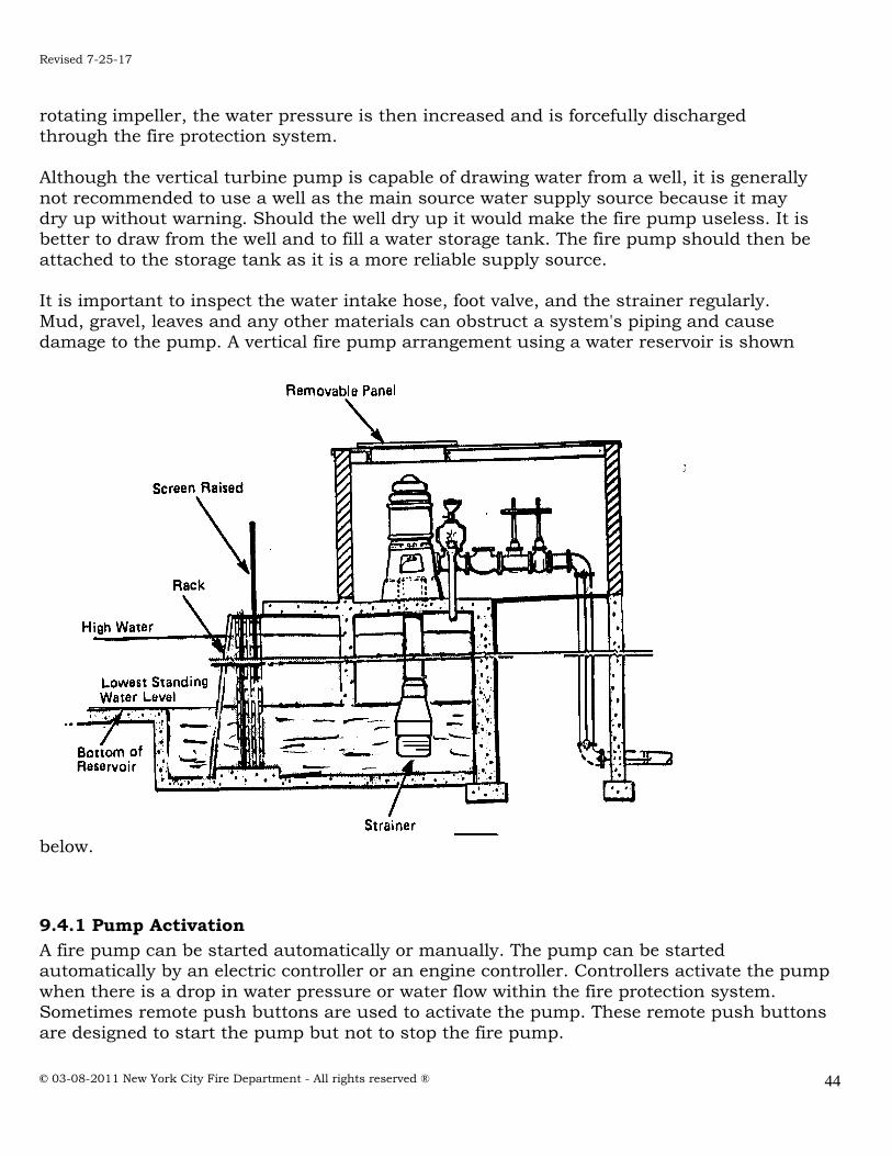
Revised 7-25-17
© 03-08-2011 New York City Fire Department - All rights reserved ®
44
rotating impeller, the water pressure is then increased and is forcefully discharged through the fire protection system.
Although the vertical turbine pump is capable of drawing water from a well, it is generally
not recommended to use a well as the main source water supply source because it may dry up without warning. Should the well dry up it would make the fire pump useless. It is better to draw from the well and to fill a water storage tank. The fire pump should then be
attached to the storage tank as it is a more reliable supply source. It is important to inspect the water intake hose, foot valve, and the strainer regularly.
Mud, gravel, leaves and any other materials can obstruct a system's piping and cause damage to the pump. A vertical fire pump arrangement using a water reservoir is shown
below.
9.4.1 Pump Activation
A fire pump can be started automatically or manually. The pump can be started automatically by an electric controller or an engine controller. Controllers activate the pump
when there is a drop in water pressure or water flow within the fire protection system. Sometimes remote push buttons are used to activate the pump. These remote push buttons
are designed to start the pump but not to stop the fire pump.

Revised 7-25-17
© 03-08-2011 New York City Fire Department - All rights reserved ®
45
Many fire pump controllers are manufactured with maximum run timers that automatically turn the fire pump OFF if an upper pressure limit has been reached. As per the FDNY Commissioner, these timers must be disabled for all automatic fire pumps in NYC.
9.5 PRESSURE MAINTENANCE PUMPS (JOCKEY PUMPS)
Jockey pumps are designed to automatically or manually operate when there is a slight drop in pressure due to the leakage within the system or a pressure surge. The jockey pump restores the pressure in the fire protection system to the required level. When the drop of
pressure within the system is greater than the capacity of the jockey pump, the fire pump is activated. Because this pump is considered a "convenience" pump and does not supply flow or pressure during the event of a fire, it does not require inspection, testing or maintenance
as per NFPA 25 or the NYC Fire Code.
9.6 FIRE PUMP LOCATION
The fire pump should be housed in a room that is fire resistant or constructed noncombustible material. The pump room should be located as close as possible to the
fire protection system. The pump room should be kept clean and accessible at all times. The fire pump, driver, and controller should be protected against possible interruption of service. The temperature inside the pump room should be maintained above 40 degrees
Fahrenheit at all times to prevent freezing of the water. The pump room should only be used for fire protection functions and not for general plant operations. No storage is
permitted in this room.
9.7 OPERATION AND SUPERVISION
When fire pumps are activated by electric automatic controllers it is essential that they are constantly monitored to ensure the availability of the electrical power supply in case of
an emergency. For this reason, supervisory devices are installed on the pumps to alert the C of F holder and/or a central station company when there is an electrical power failure. In cases where the stream turbines or internal combustion engines are used similar
supervisory devices are installed to signal when there is a problem with the controlling equipment.

Revised 7-25-17
© 03-08-2011 New York City Fire Department - All rights reserved ®
46
PART 10: INSPECTION, TESTING AND MAINTENANCE
10.1 A Complete Summary of Tasks Of Inspection, Testing & Maintenance
I. INSPECTION
A. Standpipe Systems: Gauges:
- On dry, pre-action and deluge systems shall be inspected weekly to ensure that normal air and water pressures is maintained; - Where air pressure supervision is connected to a constantly attended
location shall be inspected monthly. Alarm Devices:
- Alarm devices shall be inspected quarterly to verify that they are free of
physical damage. Buildings:
- Annually, prior to freezing weather, buildings with wet pipe systems shall be inspected to verify that window, skylights, doors ventilators, other opening and closures, blind spaces, unused attics, stair towers, roof houses and low spaces under
buildings do not expose water-filled standpipe piping to freezing and to verify that adequate heat with temperature is 40ºF (4.4ºC).
Hanger/Seismic Braces:
- Hangers installed in concealed space such as above suspended ceilings shall not need inspection;
- Hangers installed in areas that are inaccessible for safety considerations due to process operations shall be inspected during each scheduled shutdown;
- Hangers and braces shall be inspected annually from floor level to ensure they are
in place, properly aligned and otherwise not damaged. All defects and deficiencies shall be corrected.
Piping: - Piping shall be inspected annually from the floor level to ensure there is no
mechanical damage, leakage, corrosion, misalignment and that required supports
and bracing are in place and are in good condition and not missing. Nothing shall be attached to any piping system component.
- Pipe installed within concealed (such as above suspended ceilings spaces) are not
required to be inspected. Exposed piping installed in areas that are inaccessible for safety considerations due to process operations shall be inspected during each
scheduled shutdown. Hose Connections:
- Hose valves shall be inspected quarterly. The inspection shall ensure that hose caps
are in place and not damaged. Hose threads shall be inspected for damage. Valve handles shall be present and not damaged. Gaskets shall be inspected for damage or
deterioration. Hose valves shall be inspected for leaks and to ensure that no obstructions are present.

Revised 7-25-17
© 03-08-2011 New York City Fire Department - All rights reserved ®
47
- Standpipe systems hose valves equipped with pressure restricting devices shall be inspected to ensure that restricting devices are present.
Hose (as per NFPA 1962):
- Hose shall be inspected and services tested as specified NFPA 1962, within in 90 days prior to being placed in service for the first time and at least annually thereafter. Hose carried on fire apparatus shall be loaded in such a way that air
can circulate under the hose load to eliminate or reduce the growth of mildew in the hose jacket and rust and corrosion.
- Only clean, dry hose shall be placed into service.
- Hose shall be removed from the apparatus and reloaded so that the folds occur at different positions with sufficient frequency to prevent damage and the setting of
permanent folds in the rubber lining. - Large-diameter hose used to supply a pump from a hydrant shall be protected from chafing with chafing blocks or similar protection where it comes in contact with
pavement or curbing. - When connecting a pump to a hydrant, the hose shall be bent slightly to avoid
kinks when the water is turned on. - Care shall be taken to prevent the hose from chafing. - Care shall be taken to avoid dragging large-diameter fire hose, but if the hose must
be dragged, it shall be dragged when flat. - Remove and inspect the hose , including gaskets, and re-rack or re-reel at intervals in accordance with NFPA 1962.
- Occupant, and attack hose (if equipped) shall be physically inspected annually to determine that it is free from debris, that it exhibits no evidence of rot, mildew, or
damage by vermin. The inspection should also ensure that it doesn’t have burns, cuts, abrasions, coupling or nozzle damage, gaskets missing or deterioration, or incompatible threads on coupling.
- Hose must be removed from service and replaced with new hose or nozzle. - Hose shall be un-racked, unreeled, or unrolled annually. It should also be verified
that hose is not connected to hose rack nipple or valve and that hose test is not
outdated. Hose Nozzle (as per NFPA 1962):
- All nozzles shall be inspected after each use and at least annually. The inspection shall include verification of waterway clear of obstructions, no damage to tip, full operation of adjustments such as pattern selection, proper operation of shutoff
valve, no missing parts and the thread gasket in good condition. If the nozzle fails the inspection for any reason, it shall be removed from service and repaired or
replaced. Hose Rack or Storage Device:
- Storage device shall be inspected annually for damage, obstruction, difficultly in
operation, hose improperly racked or rolled, nozzle clip placement and nozzle containment.
- If enclosed in cabinet hose rack shall be inspected that it will swing out at least 90
degrees.
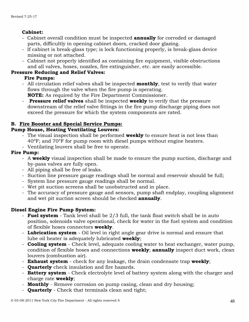
Revised 7-25-17
© 03-08-2011 New York City Fire Department - All rights reserved ®
48
Cabinet: - Cabinet overall condition must be inspected annually for corroded or damaged
parts, difficultly in opening cabinet doors, cracked door glazing. - If cabinet is break-glass type; is lock functioning properly, is break-glass device
missing or not attached. - Cabinet not properly identified as containing fire equipment, visible obstructions
and all valves, hoses, nozzles, fire extinguisher, etc. are easily accessible.
Pressure Reducing and Relief Valves: Fire Pumps:
- All circulation relief valves shall be inspected monthly, test to verify that water
flows through the valve when the fire pump is operating. NOTE: As required by the Fire Department Commissioner.
- Pressure relief valves shall be inspected weekly to verify that the pressure downstream of the relief valve fittings in the fire pump discharge piping does not
exceed the pressure for which the system components are rated.
B. Fire Booster and Special Service Pumps:
Pump House, Heating Ventilating Louvers: - The visual inspection shall be performed weekly to ensure heat is not less than 40ºF; and 70ºF for pump room with diesel pumps without engine heaters.
- Ventilating louvers shall be free to operate. Fire Pump:
- A weekly visual inspection shall be made to ensure the pump suction, discharge and
by-pass valves are fully open. - All piping shall be free of leaks.
- Suction line pressure gauge readings shall be normal and reservoir should be full; - System line pressure gauge readings shall be normal. - Wet pit suction screens shall be unobstructed and in place.
- The accuracy of pressure gauge and sensors, pump shaft endplay, coupling alignment and wet pit suction screen should be checked annually.
Diesel Engine Fire Pump System: - Fuel system - Tank level shall be 2/3 full, the tank float switch shall be in auto
position, solenoids valve operational, check for water in the fuel system and condition of flexible hoses connectors weekly.
- Lubrication system - Oil level in right angle gear drive is normal and ensure that
lube oil heater is adequately lubricated weekly; - Cooling system - Check level, adequate cooling water to heat exchanger, water pump,
condition of flexible hoses and connections weekly; annually inspect duct work, clean louvers (combustion air).
- Exhaust system - check for any leakage, the drain condensate trap weekly;
- Quarterly check insulation and fire hazards. - Battery system - Check electrolyte level of battery system along with the charger and
charge rate weekly;
- Monthly - Remove corrosion on pump casing, clean and dry housing; - Quarterly - Check that terminals clean and tight;
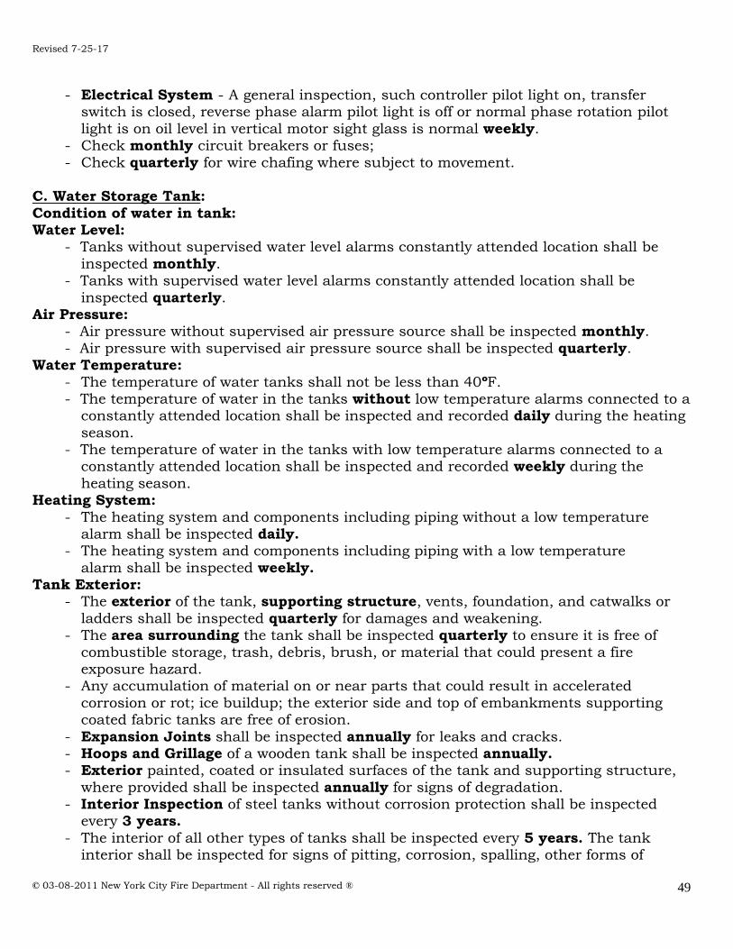
Revised 7-25-17
© 03-08-2011 New York City Fire Department - All rights reserved ®
49
- Electrical System - A general inspection, such controller pilot light on, transfer switch is closed, reverse phase alarm pilot light is off or normal phase rotation pilot
light is on oil level in vertical motor sight glass is normal weekly. - Check monthly circuit breakers or fuses;
- Check quarterly for wire chafing where subject to movement.
C. Water Storage Tank:
Condition of water in tank: Water Level:
- Tanks without supervised water level alarms constantly attended location shall be
inspected monthly. - Tanks with supervised water level alarms constantly attended location shall be
inspected quarterly. Air Pressure:
- Air pressure without supervised air pressure source shall be inspected monthly.
- Air pressure with supervised air pressure source shall be inspected quarterly. Water Temperature:
- The temperature of water tanks shall not be less than 40ºF. - The temperature of water in the tanks without low temperature alarms connected to a
constantly attended location shall be inspected and recorded daily during the heating
season. - The temperature of water in the tanks with low temperature alarms connected to a
constantly attended location shall be inspected and recorded weekly during the
heating season. Heating System:
- The heating system and components including piping without a low temperature alarm shall be inspected daily. - The heating system and components including piping with a low temperature
alarm shall be inspected weekly. Tank Exterior:
- The exterior of the tank, supporting structure, vents, foundation, and catwalks or
ladders shall be inspected quarterly for damages and weakening. - The area surrounding the tank shall be inspected quarterly to ensure it is free of
combustible storage, trash, debris, brush, or material that could present a fire exposure hazard.
- Any accumulation of material on or near parts that could result in accelerated
corrosion or rot; ice buildup; the exterior side and top of embankments supporting coated fabric tanks are free of erosion.
- Expansion Joints shall be inspected annually for leaks and cracks. - Hoops and Grillage of a wooden tank shall be inspected annually. - Exterior painted, coated or insulated surfaces of the tank and supporting structure,
where provided shall be inspected annually for signs of degradation. - Interior Inspection of steel tanks without corrosion protection shall be inspected
every 3 years.
- The interior of all other types of tanks shall be inspected every 5 years. The tank interior shall be inspected for signs of pitting, corrosion, spalling, other forms of
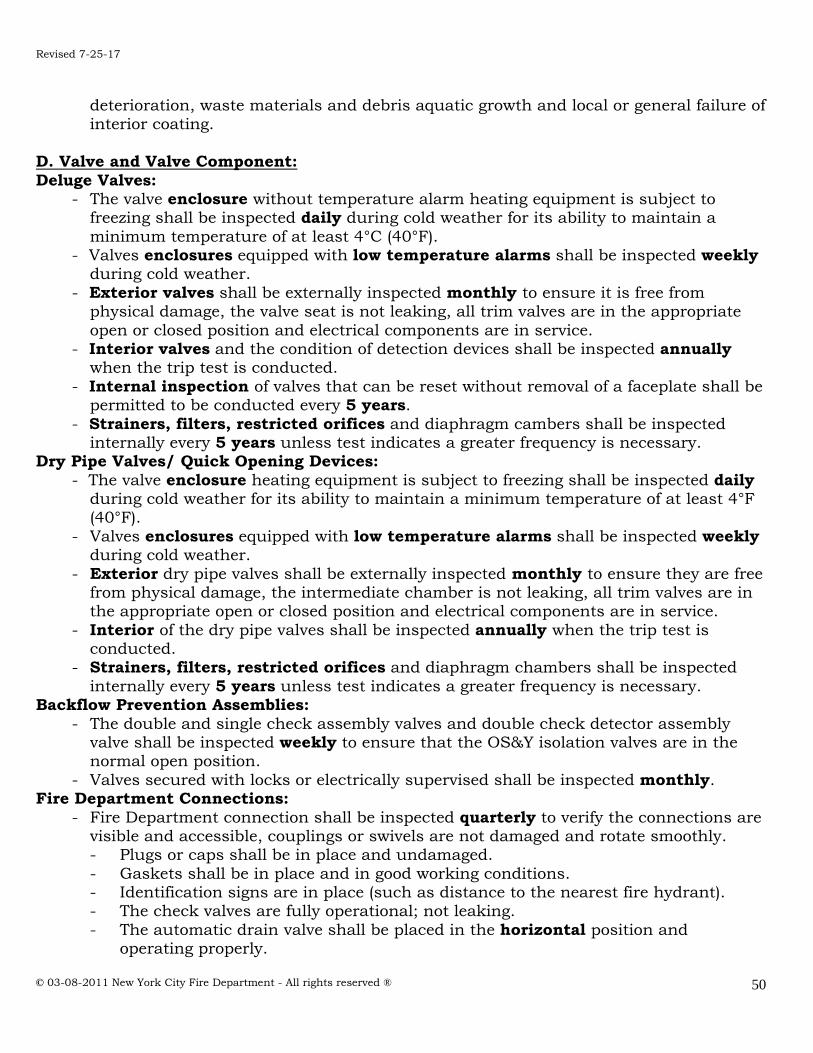
Revised 7-25-17
© 03-08-2011 New York City Fire Department - All rights reserved ®
50
deterioration, waste materials and debris aquatic growth and local or general failure of interior coating.
D. Valve and Valve Component:
Deluge Valves: - The valve enclosure without temperature alarm heating equipment is subject to
freezing shall be inspected daily during cold weather for its ability to maintain a
minimum temperature of at least 4°C (40°F). - Valves enclosures equipped with low temperature alarms shall be inspected weekly
during cold weather.
- Exterior valves shall be externally inspected monthly to ensure it is free from physical damage, the valve seat is not leaking, all trim valves are in the appropriate
open or closed position and electrical components are in service. - Interior valves and the condition of detection devices shall be inspected annually
when the trip test is conducted.
- Internal inspection of valves that can be reset without removal of a faceplate shall be permitted to be conducted every 5 years.
- Strainers, filters, restricted orifices and diaphragm cambers shall be inspected internally every 5 years unless test indicates a greater frequency is necessary.
Dry Pipe Valves/ Quick Opening Devices:
- The valve enclosure heating equipment is subject to freezing shall be inspected daily during cold weather for its ability to maintain a minimum temperature of at least 4°F (40°F).
- Valves enclosures equipped with low temperature alarms shall be inspected weekly during cold weather.
- Exterior dry pipe valves shall be externally inspected monthly to ensure they are free from physical damage, the intermediate chamber is not leaking, all trim valves are in the appropriate open or closed position and electrical components are in service.
- Interior of the dry pipe valves shall be inspected annually when the trip test is conducted.
- Strainers, filters, restricted orifices and diaphragm chambers shall be inspected
internally every 5 years unless test indicates a greater frequency is necessary. Backflow Prevention Assemblies:
- The double and single check assembly valves and double check detector assembly valve shall be inspected weekly to ensure that the OS&Y isolation valves are in the normal open position.
- Valves secured with locks or electrically supervised shall be inspected monthly. Fire Department Connections:
- Fire Department connection shall be inspected quarterly to verify the connections are visible and accessible, couplings or swivels are not damaged and rotate smoothly. - Plugs or caps shall be in place and undamaged.
- Gaskets shall be in place and in good working conditions. - Identification signs are in place (such as distance to the nearest fire hydrant). - The check valves are fully operational; not leaking.
- The automatic drain valve shall be placed in the horizontal position and operating properly.

Revised 7-25-17
© 03-08-2011 New York City Fire Department - All rights reserved ®
51
- The clappers within FDC shall be in place and operating properly. Control Valves:
- All indicating valves controlling water supplies shall be sealed, locked or provided with other approved methods as outlined in NFPA 25, 2011 edition. A seal is defined as an
easily removable device (no key required) that will indicate the unauthorized operation of a valve.
- Using this method shall require weekly inspections of each valve by the C of F holder.
All indicating valves controlling water supplies equipped with locks and/or supervised shall be inspected monthly.
- The inspection shall verify that, it is the normal open or closed position, properly
sealed, locked, or supervised, provided with appropriate wrenches, free from external leaks and provided with appropriate identification.
Alarm Valves: - Exterior alarm valves shall be externally inspected monthly to ensure the gauges
indicate normal supply water pressure is being maintained.
- The valve shall be free of physical damage and all valves are in the appropriate open or closed position. The retarding chamber or alarm drains shall be in a good condition
without leaks. - All alarm valve and their associated strainers, filters, and restricted orifices shall
be inspected internally every 5 years unless test indicates a greater frequency is
necessary. Check Valves:
- Shall be inspected internally every 5 years to verify that all components operate
correctly, move freely and are in good condition.

Revised 7-25-17
© 03-08-2011 New York City Fire Department - All rights reserved ®
52
II. TEST II. A. Standpipe Systems:
Alarm Devices:
- Vane-type and pressure type water flow alarm and supervisory devices shall be tested semi-annually to verify that they are functional.
- Mechanical water-flow devices including, but not limited to water motor gongs,
shall be tested quarterly. Gauges:
- Gauges shall be replaced every 5 yrs or tested every 5 yrs by comparison with a calibrated gauge. Gauges that are not accurate within 3% of the full scale shall be recalibrated or replaced.
B. Fire Booster and Special Service Pumps:
Pump Operation: - A monthly test of fire pump assemblies shall be conducted without flowing water and
shall be conducted by starting the pump automatically. An electric pump shall run a
minimum of 10 minutes and diesel pump shall run a minimum of 30 minutes. - An annual test of each pump assembly shall be conducted under minimum rated
and peak flows of the fire pump by controlling the quantity of water discharged
through approved test devices. The additional testing and inspection of the fire pump components shall be performed with the manufacturer’s requirements or the
alternative fire pump inspection, maintenance and procedures in NFPA 25, 2011 ed. C. Water Storage Tank: Temperature Alarms:
- Low water temperature alarms shall be tested monthly cold weather only. High Temperature Limit Switches:
- High water temperature limit switches on tank heating system shall be tested monthly whenever the heating system is in service.
Water Level Alarms:
- High and low water level alarms shall be tested semi-annually. Level Indicator:
- Level indicator shall be tested every 5 years for accuracy and freedom of movement.
Pressure Gauges: - Pressure gauges shall be tested every 5 years with a calibrated gauge according the
manufacturer’s manual. Gauges not accurate to within 3 percent of the scale of gauge being tested shall be recalibrated or replaced.
D. Valve and Valve Component: Main Drains Test:
- This test shall be conducted annually at each water-based fire protection system
riser to determine whether there has been change in the condition of the water supply piping and control valves.
- Systems where the sole water supply is through a backflow preventer and/or pressure reducing valves, the main drain test of at least one system downstream of the device shall be conducted on a quarterly basis.

Revised 7-25-17
© 03-08-2011 New York City Fire Department - All rights reserved ®
53
Dry Pipe Valves / Quick – Opening Devices: - The priming water level shall be tested quarterly. High priming water levels can affect
the operation of supervisory air or nitrogen pressure maintenance device. Testing the water level is done by opening the priming level test valve, if water flows,
drain it, close the valve when water stops flowing and air discharges, if air discharges when the valve is opened, the priming water level could be too low. To add priming water, refer to manufacturer’s instructions.
- Low air pressure alarms shall be tested quarterly in accordance with the manufacturer’s instructions.
- Quick-opening devices shall be tested quarterly following the below procedures:
- Close the system control valve, open the main drain valve and keep it in the open position, verify that the quick-opening device control valve is open. Open the
inspector’s test valve. A burst of air from device indicates that it has tripped the device’s control valve. Return the device to service in accordance with manufacturer’s instructions and return the system to service.
- Each dry pipe valve shall be trip tested annually during warm weather. Should be tested in the spring to allow time before the onset of cold weather for all water that
has entered the system or condensation to drain to low points or back to the valve. - Every 3 yrs and whenever the system is altered, the dry pipe valve shall be trip
tested with the control valve fully open and the quick – opening device in service.
- A full flow trip test - requires at least two individuals, one of whom is situated at the dry pipe valve while the other is at the inspector’s test. If possible they should in communication with each other. A full flow trip test is conducted as follows:
1- The main drain valve is fully opened to clean any accumulated scale or foreign material from the supply water piping. The main drain valve then
closed. 2- The system air or nitrogen pressure and the supply water pressure are
recorded.
3- The system air or nitrogen pressure is relieved by opening the inspector’s test valve completely. Concurrent with opening the valve, both testers start their stopwatches. If two-way communication is not available, the tester at
the dry valve is to react to the start of downward movement on the air pressure gauge.
4- Testers at the dry pipe valve note the air pressure at which the valve trips and note the tripping time.
5- Testers at the inspector’s test note the time at which water flows steadily
from the test connection. This time is noted for comparison purposes to previous tests and is not meant to be a specific pass/fail criterion. Note
that NFPA 13, does not require water delivery in 60 seconds for all systems.
6- When clean water flows, the test is terminated by closing the system
control valve. 7- The air or nitrogen pressure and the time elapsed are to be recorded as
follows:
a- from the complete opening of the test valve to the tripping of the valve,

Revised 7-25-17
© 03-08-2011 New York City Fire Department - All rights reserved ®
54
b- from the complete opening of inspector’s valve to the start of steady flow from the test connection.
8- All low point drain are opened and then closed when water ceases to flow. The dry pipe valve and quick-opening are reset, if installed, in accordance
with the manufacturer’s instruction, and the system is returned to service. Dry/Preaction System Air Leakage Test:
- Preaction systems shall be tested once every 3 years for air leakage, using
one of the following test methods: (1) A pressure test at 40 psi (3.2 bar) for 2 hours. The system shall be permitted to lose up to 3 psi (0.2 bar) during the duration of the test. Air
leaks shall be addressed if the system loses more than 3 psi (0.2 bar) during this test.
(2) With the system at normal system pressure, shut off the air source (compressor or shop air) for 4 hours. If the low air pressure alarm goes off within this period, the air leaks shall be addressed.
Pressure reducing and relief valves: Standpipe Systems Master Pressure Reducing Valves:
- Annually a full flow test shall be conducted on master pressure reducing valve stations and shall be compared to previous test result and the results from the
original installation or acceptance test.
- Quarterly, a partial flow test shall be conducted with a flow rate great enough to lift the valve seat.
Circulation Relief Valves:
- During the annual fire pump test, the closure of circulation relief valve shall be verified to be in accordance with the manufacturer’s specifications.
Pressure Relief Valves: - During the annual fire pump flow test, the pressure of relief valve shall be verified to
be correctly adjusted and set to relieve at the correct pressure and to close below that
pressure setting. Backflow prevention assemblies:
- Backflow prevention assemblies installed in fire protection system piping shall be
tested annually in accordance with the following: 1- A forward flow test shall be conducted at the system, including where hydrants
or inside hose stations are located downstream of the backflow preventer. 2- A backflow performance test, as required by the authority having jurisdiction
shall be conducted at the completion of the forward flow test.
Control Valves: - Each control valve shall be operated annually through its full range and returned
to its normal position. This test shall be conducted every time the valve is closed. Post indicator and outside screw and yoke valves shall be backed a one-quarter turn from the fully open position to prevent jamming.
- Valve supervisory switches shall be tested semiannually. A distinctive signal shall indicate movement from the valve’s normal position during either the first two revolutions of a hand wheel or when the stem of the valve has moved no more than
1/5th of the distance from its normal position. Gauges:

Revised 7-25-17
© 03-08-2011 New York City Fire Department - All rights reserved ®
55
- Gauges shall be replaced every 5 yrs or tested every 5 yrs by comparison with a calibrated gauge. Gauges that are not within 3% accurate of the full scale shall be
recalibrated or replaced. High Temperature Limit Switches:
- High water temperature limit switches on tank heating system shall be tested monthly whenever the heating system is in service.
- Hose (as per NFPA 1962), service testing of hose is undertaken to confirm its suitability
for continued use. Because there is a potential for catastrophic failure during this testing, it is important that adequate safety precautions be taken. The service test pressure for hose manufactured prior to July 1987 to meet the requirements of the
1979 and previous editions of NFPA 1962 will be 11/2 – 21/2 single jacket hose with service test pressure 150 psi. Hose manufactured in July 1987 and after to meet the
requirements of the 1987 and subsequent editions of NFPA 1962, Standard on fire Hose, is stenciled on each length of hose and read “Service Test to …PSI per NFPA 1962”.
- In-service hose shall be removed and service tested at intervals not exceeding 5 years after installation and every 3 years thereafter.
Pressure reducing and relief valves: Standpipe Systems:
- At 3 year intervals, a full flow test shall be conducted on pressure reducing valves
and shall be compared to previous test result and the results from the original installation or acceptance test. Annually, a partial flow test shall be conducted with a flow rate great enough to lift the valve seat.
Circulation Relief: - During the annual fire pump test, the closure of circulation relief valve shall be
verified to be in accordance with the manufacturer’s specifications. Pressure Relief Valves:
- During the annual fire pump flow test, the pressure of relief valve shall be
verified to be correctly adjusted and set to relieve at the correct pressure and to close below that pressure setting.
Standpipe systems equipped with hose racks:
- A full flow test shall be conducted on each valve at 5 years intervals and shall be compared to previous test results.
Hydrostatic test (5 years) See NYC Fire Code section 905.12.1 - Upon order of the commissioner, but at least once every 5 years, the standpipe
system shall be subjected to a hydrostatic pressure test and a flow test to
demonstrate its suitability for department use. These tests shall be conducted in compliance with the requirements of the rules and shall be conducted at the
owner's risk, by his or her representative before a representative of the Fire Department.
Rooftop Standpipe System Flow Test
- At least every 5 years a flow test shall be conducted at the hydraulically most remote hose connections of each zone of an automatic standpipe system to verify that the water supply still provides the designed pressure of the required flow.
All systems shall be flow tested and pressure tested at the requirements at the designed criteria in effect at the time of installation, or as required by the FDNY.

Revised 7-25-17
© 03-08-2011 New York City Fire Department - All rights reserved ®
56
III. MAINTENANCE
A. Standpipe Systems: Valves (ALL TYPES)
Control Valves: - The operating stems of outside screw and yoke valves shall be lubricated annually.
The valve then shall be completely closed and reopened to test its operation and
distribute the lubricant. Low point drains (dry pipe system):
- Shall be drained after each operation and before the onset of freezing weather
conditions and thereafter as needed. Hose Connections
The following devices must be maintained, repaired and/or replaced annually: - missing cap, valve handles, restricting device and cap gaskets must be replaced. - damaged fire hose connection, deteriorated cap gaskets and leaking valves must
repaired. - manual, semiautomatic, or dry standpipe that does not operate smoothly must be
repaired or lubricated. B. Fire Booster and Special Service Pumps:
- A preventive maintenance program shall be maintained on all components of the pump assembly in accordance with manufacturer’s recommendations. If there is no manufacturer’s recommendations for preventive maintenance use Table 8.5.3 of NFPA
25, 2011.
C. Water Storage Tank: Water Level:
- Tank shall be maintained full or at the designed water level.
Drain Silt - Silt shall be removed during interior inspection (semiannually) or more frequently as
needed to avoid accumulation to the level of the tank outlet.
Embankment-Supported Coated Fabric (ESCF) Suction Tanks: - The maintenance of ESCF tanks shall be done according the tank manufacturer
manual. D. Valve and Valve Component:
Control Valves: - The operating stems of outside screw and yoke valves shall be lubricated annually.
The valve then shall be completely closed and reopened to test its operation and distribute the lubricant.
Pre-action/ Valves
- During the annual trip test, the interior of the pre-action or deluge valve shall be cleaned thoroughly and the parts replaced or repaired as necessary.
Dry Pipe Valves / Quick – Opening Devices
- During the annual trip test, the interior of the pre-action or deluge valve shall be cleaned thoroughly and the parts replaced or repaired as necessary.
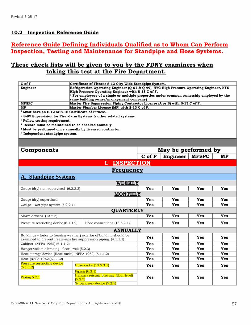
Revised 7-25-17
© 03-08-2011 New York City Fire Department - All rights reserved ®
57
10.2 Inspection Reference Guide
Reference Guide Defining Individuals Qualified as to Whom Can Perform Inspection, Testing and Maintenance for Standpipe and Hose Systems. These check lists will be given to you by the FDNY examiners when taking this test at the Fire Department.
C of F Certificate of Fitness S-13 City Wide Standpipe System. Engineer Refrigeration Operating Engineer (Q-01 & Q-99), NYC High Pressure Operating Engineer, NYS
High Pressure Operating Engineer with S-13 C of F.
*(For employees of a single or multiple properties under common ownership employed by the same building owner/management company)
MFSPC Master Fire Suppression Piping Contractor License (A or B) with S-13 C of F. MP Master Plumber License (MP) with S-13 C of F. 1 Must have an S-12 or S-15 Certificate of Fitness. 2 S-95 Supervision for Fire alarm Systems & other related systems. 3 Follow testing requirement. 4 Record must be maintained to be checked annually. 5 Must be performed once annually by licensed contractor. 6 Independent standpipe system.
Components May be performed by
C of F Engineer MFSPC MP
I. INSPECTION
Frequency
A. Standpipe Systems WEEKLY
Gauge (dry) non supervised (6.2.2.2) Yes Yes Yes Yes
MONTHLY Gauge (dry) supervised Yes Yes Yes Yes Gauge – wet pipe system (6.2.2.1) Yes Yes Yes Yes
QUARTERLY Alarm devices (13.2.6) Yes Yes Yes Yes
Pressure restricting device (6.1.1.2) Hose connections (13.5.2.1) Yes Yes Yes Yes
ANNUALLY Buildings – (prior to freezing weather) exterior of building should be examined to prevent freeze-ups fire suppression piping. (4.1.1.1) Yes Yes Yes Yes
Cabinet (NFPA 1962) (6.1.1.2) Yes Yes Yes Yes Hanger/seismic bracing (floor level) (5.2.3) Yes Yes Yes Yes Hose storage device (Hose racks) (NFPA 1962) (6.1.1.2) Yes Yes Yes Yes Hose (NFPA 1962)(6.1.1.2) Yes Yes Yes Yes Pressure restricting device (6.1.1.2)
Hose racks (13.5.3.1) Yes Yes Yes Yes
Piping 6.2.1
Piping (6.2.1)
Yes Yes Yes Yes Hanger/seismic bracing (floor level)
(5.2.3)
Supervisory device (5.2.5)

Revised 7-25-17
© 03-08-2011 New York City Fire Department - All rights reserved ®
58
Components May be performed by
C of F Engineer MFSPC MP
I. INSPECTION
B. Fire, Booster and Special Service Pumps WEEKLY
Pump house, heating ventilating louvers (8.2.2(1)) Yes Yes Yes Yes Fire pump system (8.2.2) Yes Yes Yes Yes
Diesel Engine System
Fuel
Tank level (8.1.2)
Yes
Yes
Yes
Yes
Tank float switch (8.1.2)
Solenoids valve operation (8.1.2)
Water in the fuel system
(8.1.2)
Flexible hoses and connectors (8.1.2)
Piping (8.2.2)
Tank vents and overflow piping unobstructed (8.2.2)
Lubrication system
Oil level (8.1.2)
Lube oil heater (8.1.2)
Crankcase breather (8.1.2)
Cooling system
Level (8.1.2)
Adequate cooling water to
heat exchanger (8.1.2)
Water pumps (8.1.2)
Conditions of flexible hoses &
connection (8.1.2)
Jacket water heater (8.1.2)
Exhaust system
Leakage (8.1.2)
Drain condensate trap (8.1.2)
Hangers & supports (8.1.2)
Flexible exhaust section (8.1.2)
Electrical system
General inspection (8.1.2)
Operation of safeties & alarms (8.1.2)
Circuit breakers or fuses
(8.1.2)
MONTHLY
Diesel Engine System
Circuit breakers or fuses
(8.1.2) Yes Yes Yes Yes
Charger & charge rate (8.1.2) Yes Yes Yes Yes
QUARTERLY
Diesel Engine System
Exhaust system Insulation & fire hazards (8.1.2)
Yes Yes Yes Yes Electrical system Wire chafing where subject to
movement (8.1.2) SEMIANNUALLY
Diesel Engine System
Electrical system
Operation of safeties and alarms (8.1.2)
Yes Yes Yes Yes

Revised 7-25-17
© 03-08-2011 New York City Fire Department - All rights reserved ®
59
Components May be performed by
C of F Engineer MFSPC MP
I. INSPECTION
B. Fire, Booster and Special Service Pumps ANNUALLY
Fire pump
system
Check accuracy of pressure gauges and sensors (8.1.2)
Yes Yes Yes Yes Check pump shaft endplay, coupling alignment
(8.1.2)
Wet pit suction screens (after each pump operation) (8.1.2)
Diesel Engine System
Cooling system
Inspect duct work, clean louvers (combustion air) (8.1.2)
Yes Yes Yes Yes
Electrical
system 2
Inspect emergency manual starting means (without power) (8.1.2)
Yes Yes Yes Yes Tighten electrical connections as necessary (8.1.2)
Lubricate mechanical moving parts (excluding starters & relays) (8.1.2)
Calibrate pressure switch settings (8.1.2)
C. Water Storage Tank DAILY
Water temperature – without low temperature alarms (cold weather) (9.2.4.3) Yes Yes Yes Yes
Heating System – without low temperature alarms (cold weather)
(9.2.3.2) Yes Yes Yes Yes
WEEKLY Temperature alarms not connected to constantly connected location
(9.2.3.1) Yes Yes Yes Yes
Water temperature - with low temperature alarms NOT connected to a constantly attended location (cold weather) (9.2.4.3)
Yes Yes Yes Yes
Heating system and components – with low temperature alarms (cold weather) (9.2.3.1)
Yes Yes Yes
Yes
MONTHLY Condition of water in tank – without water level alarms (cold weather) (9.2.4.3)
Yes Yes Yes Yes
Temperature alarms connected to constantly attended location (9.2.4.2)
Yes Yes Yes Yes
Water temperature - with low temperature alarms connected to a constantly attended location (heating season) (9.2.4.3)
Yes Yes Yes Yes
Water level (without water level alarms) (9.1.1.2) Yes Yes Yes Yes Air pressure - (without supervised air pressure source) (9.1.1.2) Yes Yes Yes Yes
QUARTERLY
Condition of water in tank - with water level temperature alarms (cold weather below 40ºF)
Yes Yes Yes Yes
Water level (with supervised water level alarms) (9.2.1.1) Yes Yes Yes Yes Air pressure – (with supervised air pressure source) (9.2.2.1) Yes Yes Yes Yes
Tank – exterior
Support structure (9.2.5.1)
Yes Yes Yes Yes Catwalks and ladders (9.2.5.1)
Surrounding area (9.2.5.2)
ANNUALLY
Embankment-supported coated fabric (ESCF) suction tanks (9.4.6) Yes Yes Yes Yes Exterior (paint, coat or insulated surfaces) (9.2.5.5) Yes Yes Yes Yes Hoops and grillage of wooden tanks (AKA Dunnage) (9.2.5.4) Yes Yes Yes Yes

Revised 7-25-17
© 03-08-2011 New York City Fire Department - All rights reserved ®
60
Components May be performed by
C of F Engineer MFSPC MP
I. INSPECTION
C. Water Storage Tank ANNUALLY
Expansion Joints (9.2.5.3) Yes Yes Yes Yes
3 YEARS Interior – (steel tanks without corrosion protection) (9.2.6.1.1) Yes Yes Yes Yes
5 YEARS Interior - all other types of tanks (9.2.6.1.2) Yes Yes Yes Yes
D. Valve and Valve component DAILY
Dry valve - valve enclosure without temperature alarm (during cold
weather) (13.4.3.1.1) Yes Yes Yes Yes
Dry pipe valves and quick opening devices – valve enclosure without temperature alarm (during cold weather)
Yes Yes Yes Yes
WEEKLY
Control Valves Sealed (13.3.2.1) Yes Yes Yes Yes Dry valves - valve enclosure equipped with low temperature alarms (during cold weather) (13.4.3.1.1.1)
Yes Yes Yes Yes
Dry pipe valves and quick opening devices – valve enclosure equipped
with low temperature alarms ( during cold weather) (13.4.4.1.1.1)
Yes
Yes Yes Yes
Pressure reducing & Relief valves
Diesel Fire Pumps
Casing relief valves
(13.5.7.1) Yes Yes Yes Yes
Pressure relief valves (13.5.7.2)
Backflow Prevention assemblies (not secured with locks or electrically supervised)
Reduced pressure (13.6.1)
Yes Yes Yes Yes Reduced pressure
detectors (13.6.1) MONTHLY
Control Valves Locked (13.3.2.1.1)
Yes Yes Yes Yes Tamper switches (13.3.2.1.1)
Alarm valves Exterior (13.4.1.1) Yes Yes Yes Yes Deluge valves – Exterior (13.4.3.1.6) Yes Yes Yes Yes Dry pipe valves and quick opening devices - Exterior (13.4.4.1.4) Yes Yes Yes Yes Pressure regulating & Relief valves
Electric Fire Pumps
Casing relief valves (8.2) Yes Yes Yes Yes
Pressure relief valves (8.2)
Backflow Prevention assemblies (secured
with locks or electrically supervised) (13.6.1)
reduced pressure (13.6.1)
Yes Yes Yes Yes reduced pressure detectors (13.6.1)
QUARTERLY
Pressure regulating & Relief valves
Hose connections (13.5)
Yes Yes Yes Yes Floor markings (13.5.6.1.8)
Calibration (13.5.6.1.8)
Setting notches (13.5.6.1.8)
Fire Department Connections
(13.7.1)
Caps combination with standpipe/sprinkler ( should be painted yellow
Yes Yes Yes Yes Swivel turn freely
Ball drip
Signage
Hose Valve (13.5.6.1) Yes Yes Yes Yes
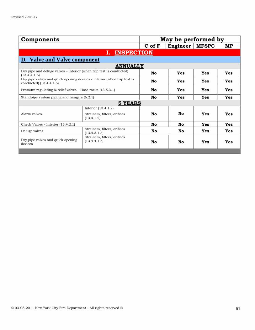
Revised 7-25-17
© 03-08-2011 New York City Fire Department - All rights reserved ®
61
Components May be performed by
C of F Engineer MFSPC MP
I. INSPECTION
D. Valve and Valve component ANNUALLY
Dry pipe and deluge valves – interior (when trip test is conducted) (13.4.4.1.5)
No Yes Yes Yes
Dry pipe valves and quick opening devices - interior (when trip test is
conducted) (13.4.4.1.5) No Yes Yes Yes
Pressure regulating & relief valves – Hose racks (13.5.3.1) No Yes Yes Yes
Standpipe system piping and hangers (6.2.1) No Yes Yes Yes
5 YEARS
Alarm valves
Interior (13.4.1.2)
No
No
Yes
Yes
Strainers, filters, orifices
(13.4.1.2)
Check Valves - Interior (13.4.2.1) No No Yes Yes
Deluge valves Strainers, filters, orifices (13.4.3.1.8) No No Yes Yes
Dry pipe valves and quick opening devices
Strainers, filters, orifices (13.4.4.1.6)
No No Yes Yes
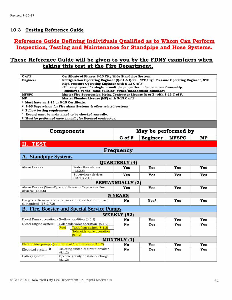
Revised 7-25-17
© 03-08-2011 New York City Fire Department - All rights reserved ®
62
10.3 Testing Reference Guide
Reference Guide Defining Individuals Qualified as to Whom Can Perform Inspection, Testing and Maintenance for Standpipe and Hose Systems.
These Reference Guide will be given to you by the FDNY examiners when taking this test at the Fire Department.
C of F Certificate of Fitness S-13 City Wide Standpipe System. Engineer Refrigeration Operating Engineer (Q-01 & Q-99), NYC High Pressure Operating Engineer, NYS
High Pressure Operating Engineer with S-13 C of F (For employees of a single or multiple properties under common 0wnership employed by the same building owner/management company)
MFSPC Master Fire Suppression Piping Contractor License (A or B) with S-13 C of F. MP Master Plumber License (MP) with S-13 C of F. 1 Must have an S-12 or S-15 Certificate. 2 S-95 Supervision for Fire alarm Systems & other related systems. 3 Follow testing requirement. 4 Record must be maintained to be checked annually. 5 Must be performed once annually by licensed contractor.
Components May be performed by
C of F Engineer MFSPC MP
II. TEST
Frequency
A. Standpipe Systems QUARTERLY (4)
Alarm Devices
Water flow alarms (13.2.6)
Yes Yes Yes Yes
Supervisory devices (13.4.3.2.13)
Yes Yes Yes Yes
SEMIANNUALLY (2) Alarm Devices (Vane-Type and Pressure Type water flow devices) (13.2.6)
Yes Yes Yes Yes
5 YEARS Gauges - Remove and send for calibration test or replace as required (13.2.7.2)
No Yes4 Yes Yes
B. Fire, Booster and Special Service Pumps WEEKLY (52)
Diesel Pump operation - No-flow condition (8.3.1) No Yes Yes Yes Diesel Engine system
Solenoids valve operation (8.1.2) No Yes Yes Yes Fuel Tank float switch (8.1.2)
Solenoids valve operation
(8.1.2)
MONTHLY (1) Electric Fire pump - (minimum of 10 minutes) (8.3.1.2) No Yes Yes Yes Electrical system 2 Isolating switch & circuit breaker
(8.1.2) No Yes Yes Yes
Battery system Specific gravity or state of charge (8.1.2)

Revised 7-25-17
© 03-08-2011 New York City Fire Department - All rights reserved ®
63
Components May be performed by
C of F Engineer MFSPC MP
II. TEST
Frequency
B. Fire, Booster and Special Service Pumps SEMIANNUALLY (2)
Electrical system 2 Operate manual starting means
(electrical) (8.1.2) No Yes4
Yes Yes
Diesel Engine System
Cooling system Antifreeze protection level (8.1.2)
No Yes Yes Yes
Electrical system
Operation of safeties and
alarms (8.1.2)
ANNUALLY (1) Pump operation - Full flow condition (8.3.3) No No Yes Yes Electrical system 2 Trip circuit breaker (if mechanism
provided) (8.1.2) No No
Yes Yes
Operate emergency manual starting means (without power)
(8.1.2)
Exhaust system Excessive back pressure (8.1.2) No No Yes Yes Diesel Engine System Tank vents and overflow piping
unobstructed (8.1.2) No No Yes Yes
C. Water Storage Tank MONTHLY (12)
Temperature alarms (cold weather) (9.3.3) No Yes5 Yes Yes High temperature limit switches (whenever the heating system is in service) (9.3.4)
No Yes5 Yes Yes
SEMIANNUALLY (2) Water level alarms (9.3.5) No Yes5 Yes Yes
5 YEARS Level indicators (9.3.1) No Yes5 Yes Yes Pressure gauges (9.3.6.1) No Yes5 Yes Yes
D. Valve and Valve Component QUARTERLY (4)
Main drain (where the sole water supply is through a
backflow preventer and/or pressure reducing valves) (13.3.3.4)
No Yes Yes Yes1
Dry pipe valves and quick opening devices
Priming water (13.4.3.2.1) No Yes5 Yes Yes Low air pressure alarm (13.4.4.2.6)
Quick-opening devices (13.4.4.2.4)
SEMIANNUALLY (2) Control Valves Tamper Switch
Supervisory Alarm (13.3.3.5) No Yes5 Yes Yes
ANNUALLY (1) Hose Nozzle (NFPA 1962) (6.1.1.2) No No Yes Yes Hose Storage device, racks (NFPA 1962) (6.1.1.2) No No Yes Yes Standpipe – hose valve (Class I and Class III) (13.5.6.2.1) No Yes Yes Yes Main drain (13.2.5) No No Yes Yes1

Revised 7-25-17
© 03-08-2011 New York City Fire Department - All rights reserved ®
64
Components May be performed by
C of F Engineer MFSPC MP
II. TEST
Frequency
D. Valve and Valve Component ANNUALLY (1)
Dry pipe valves and
Quick opening devices
Trip test (13.4.4.2.2) No No Yes Yes
Control Valves Position (13.3.3.1) No No Yes Yes Operation (13.3.3.1)
Pressure reducing
and Relief valves
Circulation relief (13.5.7.1.2) No No Yes Yes Pressure relief valves (13.5.7.2.2)
Backflow prevention Assemblies (13.6.2) No No Yes Yes
3 YEARS Hose 1962 (NFPA 1962) No Yes Yes Yes
Dry pipe valves and quick opening devices
Full flow trip test (13.4.3.2.2) No No Yes Yes
Pressure reducing valve flow test No No Yes Yes
5 YEARS Hose (NFPA 1962) No Yes Yes Yes Hydrostatic Test (6.3.2) No No Yes Yes Standpipe system full flow test (6.3.1) No No Yes Yes Gauges - Remove and send for calibration test or replace as
required (13.2.7.2) No Yes4 Yes Yes

Revised 7-25-17
© 03-08-2011 New York City Fire Department - All rights reserved ®
65
10.4 Maintenance Reference Guide
Reference Guide Defining Individuals Qualified as to Whom Can Perform Inspection, Testing and Maintenance for Standpipe and Hose Systems. These Reference Guide will be given to you by the FDNY examiners when taking this test at the Fire Department.
C of F
Certificate of Fitness S-13 City Wide Standpipe System
Engineer Refrigeration Operating Engineer (Q-01 & Q-99), NYC High Pressure Operating Engineer, NYS
High Pressure Operating Engineer with S-13 C of F. (For employees of a single or multiple properties under common 0wnership employed by the same building owner/management company).
MFSPC Master Fire Suppression Piping Contractor License (A or B) with S-13 C of F. MP Master Plumber License (MP) with S-13 C of F. 1 Must have an S-12 or S-15 Certificate of Fitness. 2 S-95 Supervision for Fire alarm Systems & other related systems. 3 Follow testing requirement. 4 Record must be maintained to be checked annually. 5 Must be performed once annually by licensed contractor.
Components May be performed by
C of F Engineer MFSPC MP
III. MAINTENANCE
A. Standpipe Systems ANNUALLY (1)
Valves (all types) Control valves (13.3.4) No No Yes Yes Dry pipe valves /quick opening devices (13.3.4)
No No Yes Yes
Low point drains - (Dry pipe systems) (AS NEEDED and
before freezing conditions) (13.4.4.3.2) No No Yes Yes
Hose Connections
(6.1.2)
Lubricate No Yes Yes Yes Repair No Yes Yes Yes Replace No Yes Yes Yes
5 YEARS Obstruction Investigation (14.2.1) No No Yes Yes
B. Fire, Booster and Special Service Pumps WEEKLY (52)
Diesel engine
system Fuel Clean water in the
system (8.1.2) No Yes5 Yes Yes
MONTHLY (12) Diesel engine
system Battery system Remove corrosion, case
exterior clean and dry (8.1.2)
No Yes5 Yes Yes
QUARTERLY (4)
Diesel engine system
Fuel Clean Strainer, filter or dirt leg or combination
(8.1.2)
No
Yes5
Yes
Yes
Lubricating system
Crankcase breather (8.1.2)
Cooling system Water strainer (8.1.2)

Revised 7-25-17
© 03-08-2011 New York City Fire Department - All rights reserved ®
66
Components May be performed by
C of F Engineer MFSPC MP
III. MAINTENANCE
B. Fire, Booster and Special Service Pumps SEMI-ANNUALLY (2)
Diesel engine system
Electrical system
Boxes, panels and cabinets
(8.1.2) No Yes5 Yes Yes
Circuit breakers or fuses (8.1.2)
ANNUALLY (1) Hydraulic (8.1.1.2) No No Yes Yes
Pump system
Lubricate pump bearings (8.1.2)
No
No
Yes
Yes
Check accuracy of pressure gauges & sensors (8.1.2)
Wet pit suction screens (after each pump
operation) (8.1.2)
Mechanical transmission
Lubricate coupling (8.1.2) No No Yes Yes Lubricate right angle gear drive (8.1.2)
Electrical system
Grease motor bearings (8.1.2) No No Yes Yes
Controller, various components (8.5 – varies) No No Yes Yes Motor (8.1.1.2) No No Yes Yes
Diesel engine system various components
Cooling system Inspect duct work
clean louvers (8.1.2)
No
No
Yes
Yes Rod out heat exchanger (8.1.2)
Lubrication system
Oil change (8.1.2)
Oil filters (8.1.2)
Exhaust system Excessive back pressure (8.1.2)
C. Water Storage Tank Water level (as required ) (9.4.2) Yes Yes Yes Yes
SEMIANNUALLY (2) Drain silt No Yes5 Yes Yes
EVERY TWO (2) YEARS Embankment-supported coated fabric (ESCF) suction
tanks (9.4.6.2) No No Yes Yes
D. Valve and Valve Component ANNUALLY (1)
Control valves (13.3.4) No No Yes Yes Dry Pipe Valves and Quick-Opening Devices (13.4.4.3) No No Yes Yes

Revised 7-25-17
© 03-08-2011 New York City Fire Department - All rights reserved ®
67
10.5 Inspection, Maintenance & Testing Notification Activities
Red Tag - Notify FDNY & owner immediately (shall be fixed Immediately) FC 901.7
Orange Tag -Notify the owner immediately - If deficiency is not corrected after 30 days Notify FDNY
Yellow Tag -Notify the owner immediately - If deficiency is not corrected after 30 days Notify FDNY
Green Tag - System Fully operational
Components
Inspection Activities (Reference NFPA 25 –
2011)
Notification of System Shut Down
Components Checked
Satisfactory
(Yes or No) If No, explain
Impairment - Red Tag Critical Deficiency – Orange Tag Non-Critical Deficiency –
Yellow Tag System Fully operational- Green tag
I. INSPECTION
A. Standpipe & Hose Systems Standpipe system Shut down
Partial or Full shut down (6.1) Red Yes No
No Access Control Valves - Inaccessible for more than 30 days (13.2.7.1)
Red Yes No
Pipe and Fittings Leaking (5.2.2) Red Yes No
Hose Cuts, couplings not of compatible threads (6.2.1) NFPA 1962
Orange Yes No
Hose Deterioration, no gasket or damaged gaskets (6.2.1) NFPA 1962
Orange Yes No
Hose Mildew present, corrosion present, hose not connected (6.2.1) NFPA
1962
Yellow Yes No
Hose nozzle Missing, broken parts or thread gasket damaged (6.2.1) NFPA 1962
Orange Yes No
Hose storage Hose not properly racked or rolled, nozzle clip missing, nozzle not contained, damaged obstructed
(6.2.1) NFPA 1962
Orange Yes No
Cabinet Corroded or damaged parts, not easy to open, not accessible, not
identified, door glazing in poor condition, lock not functioning in break glass type, valve, hose nozzle, fire extinguisher, etc, not readily accessible (6.2.1) NFPA 1962
Orange Yes No
Pipe and fittings
Poor condition/external corrosion, mechanical damage, not properly aligned, external loads (6.2.1)
Orange Yes No
Pipe and fittings Subject to freezing conditions
(6.2.1) Orange Yes No
Hangers & seismic braces
Damaged or loose (5.2.3) Yellow Yes No
Gauges Poor Condition (5.2.4.1) Yellow Yes No
Gauges Not showing normal water/air pressure (5.2.4.1, 5.2.4.2)
Orange Yes No
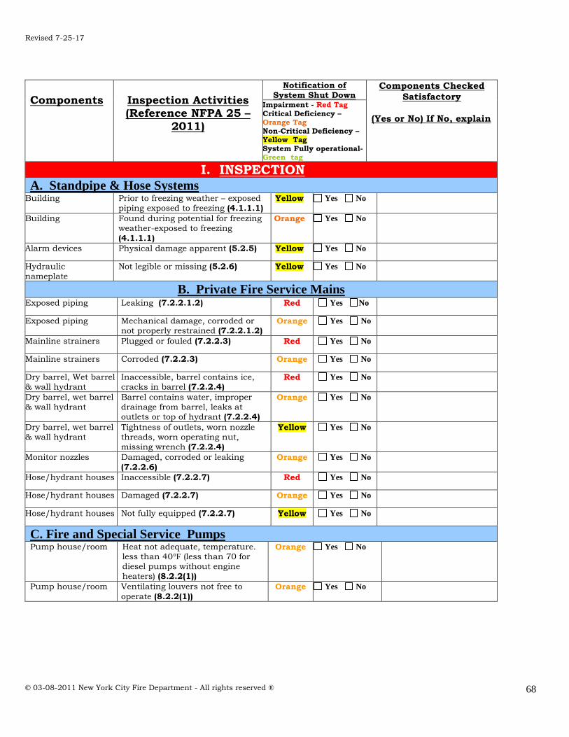
Revised 7-25-17
© 03-08-2011 New York City Fire Department - All rights reserved ®
68
Components
Inspection Activities (Reference NFPA 25 –
2011)
Notification of System Shut Down
Components Checked
Satisfactory
(Yes or No) If No, explain
Impairment - Red Tag
Critical Deficiency – Orange Tag Non-Critical Deficiency – Yellow Tag
System Fully operational- Green tag
I. INSPECTION
A. Standpipe & Hose Systems Building Prior to freezing weather – exposed
piping exposed to freezing (4.1.1.1) Yellow Yes No
Building Found during potential for freezing weather-exposed to freezing
(4.1.1.1)
Orange Yes No
Alarm devices Physical damage apparent (5.2.5) Yellow Yes No
Hydraulic nameplate
Not legible or missing (5.2.6) Yellow Yes No
B. Private Fire Service Mains Exposed piping Leaking (7.2.2.1.2) Red Yes No
Exposed piping Mechanical damage, corroded or not properly restrained (7.2.2.1.2)
Orange Yes No
Mainline strainers Plugged or fouled (7.2.2.3) Red Yes No
Mainline strainers Corroded (7.2.2.3) Orange Yes No
Dry barrel, Wet barrel & wall hydrant
Inaccessible, barrel contains ice, cracks in barrel (7.2.2.4)
Red Yes No
Dry barrel, wet barrel & wall hydrant
Barrel contains water, improper drainage from barrel, leaks at outlets or top of hydrant (7.2.2.4)
Orange Yes No
Dry barrel, wet barrel & wall hydrant
Tightness of outlets, worn nozzle threads, worn operating nut, missing wrench (7.2.2.4)
Yellow Yes No
Monitor nozzles Damaged, corroded or leaking
(7.2.2.6) Orange Yes No
Hose/hydrant houses Inaccessible (7.2.2.7) Red Yes No
Hose/hydrant houses Damaged (7.2.2.7) Orange Yes No
Hose/hydrant houses Not fully equipped (7.2.2.7) Yellow Yes No
C. Fire and Special Service Pumps Pump house/room Heat not adequate, temperature.
less than 40°F (less than 70 for diesel pumps without engine heaters) (8.2.2(1))
Orange Yes No
Pump house/room Ventilating louvers not free to
operate (8.2.2(1)) Orange Yes No

Revised 7-25-17
© 03-08-2011 New York City Fire Department - All rights reserved ®
69
Components
Inspection Activities (Reference NFPA 25 –
2011)
Notification of System Shut Down
Components Checked
Satisfactory
(Yes or No) If No, explain
Impairment - Red Tag
Critical Deficiency – Orange Tag Non-Critical Deficiency – Yellow Tag
System Fully operational- Green tag
I. INSPECTION
C. Fire and Special Service Pumps
Pump system Suction, discharge or bypass valves not fully open, pipe leaking, suction
line & system line pressure not normal, wet pit suction screens obstructed (8.2.2(2))
Red Yes No
Pump system Suction reservoir not full, wet pit suction screens missing (8.2.2(2))
Orange Yes No
Electrical system No electrical power - controller pilot light not illuminated, transfer switch pilot light not illuminated, isolating switch not closed, reverse
phase alarm pilot light on or normal phase light is off, oil level in vertical motor sight glass not normal
(8.2.2(3))
Red Yes No
Electrical system Circuit breakers and fuses over two years old (8.2.2)
Orange Yes No
Electrical system Electrical power is provided – controller pilot light not illuminated, transfer switch pilot light not illuminated, reverse phase alarm pilot light on or normal phase light is not illuminated
(8.2.2(3))
Yellow Yes No
Diesel engine system
Fuel tank less than two-thirds full, controller selector switch not in auto position, battery voltage readings not normal, battery charging current not normal, battery pilot lights off or battery
failure pilot lights on alarm pilot lights are on, engine running time meter not reading, oil level in right angle gear drive not normal, crankcase oil level not normal, cooling water level not normal, electrolyte level in batteries not normal, battery terminals corroded, water-jacket heater not operating
(8.2.2(4))
Orange Yes No
Steam System Steam pressure gauge reading not normal (8.2.2(5))
Orange Yes No

Revised 7-25-17
© 03-08-2011 New York City Fire Department - All rights reserved ®
70
Components
Inspection Activities (Reference NFPA 25 –
2011)
Notification of System Shut Down
Components Checked
Satisfactory
(Yes or No) If No, explain
Impairment - Red Tag
Critical Deficiency – Orange Tag Non-Critical Deficiency – Yellow Tag
System Fully operational- Green tag
I. INSPECTION
D. Water Storage Tanks Water level Water level and /or condition not
correct (9.2.1) Orange Yes No
Air pressure Air pressure in pressure tanks not correct (9.2.2)
Red Yes No
Heating system Heating system not operational, water temperature below 40
(9.2.3)
Orange Yes No
Exterior Tank exterior, supporting
structure, vents, foundation, catwalks or ladders where provided damaged (9.2.5.1)
Yellow Yes No
Exterior Area around tank has fire exposure hazard in form of combustible storage, trash, debris, brush or material
(9.2.5.2)
Yellow Yes No
Exterior Accumulation of material on or near parts that could result in accelerated corrosion or rot
(9.2.5.2)
Yellow Yes No
Exterior Ice buildup on tank and support
(9.2.5.2) Orange Yes No
Exterior Erosion exists on exterior sides or top of embankments supporting coated fabric tanks (9.2.5.2)
Yellow Yes No
Exterior Expansion joints leaking or cracking (9.2.5.3)
Orange Yes No
Exterior Hoops and grills of wooden tanks in poor condition (9.2.5.4)
Yellow Yes No
Exterior Exterior painted, coated, or
insulated surfaces of tanks or
supporting structure degraded
(9.2.5.5)
Yellow Yes No
Interior (pressure tanks or steel tanks w/o corrosion protection every 3 years, all others every 5 years)
Pitting, corrosion, spalling , rot other forms of deterioration, waste materials exist, aquatic growth, local or general failure of interior coating (9.2.6.3)
Yellow Yes No
Interior (pressure tanks or steel tanks w/o corrosion protection every 3 years, all others every 5 years)
Voids beneath floor with stand in the middle of tanks on ring type foundations (9.2.6.5)
Yellow Yes No

Revised 7-25-17
© 03-08-2011 New York City Fire Department - All rights reserved ®
71
Components
Inspection Activities (Reference NFPA 25 –
2011)
Notification of System Shut Down
Components Checked
Satisfactory
(Yes or No) If No, explain
Impairment - Red Tag
Critical Deficiency – Orange Tag Non-Critical Deficiency – Yellow Tag
System Fully operational- Green tag
I. INSPECTION
D. Water Storage Tanks Interior (pressure
tanks or steel tanks w/o corrosion protection every 3 years, all others every 5 years)
Heating system components or
piping in poor condition (9.2.6.6) Yellow Yes No
Interior (pressure tanks or steel tanks w/o corrosion protection every 3 years, all others every 5 years)
Blockage of anti-vortex plate
(9.2.6.7) Red Yes No
Interior (pressure
tanks or steel tanks w/o corrosion protection every 3 years, all others every 5 years)
Deterioration of anti-vortex plate
(9.2.6.7)
Orange Yes No
E. Valves, Valve components, and Trim
Gauges Poor condition (13.2.7.1) Yellow Yes No
Gauges Not showing normal water/air pressure (13.2.7.1)
Orange Yes No
Control valve Improper closed position
(13.3.2.2) Red Yes No
Control valve Improper open position, leaking
(13.3.2.2) Orange Yes No
Control valve Not sealed, locked or supervised, not accessible, no appropriated
wrench if required, and no identification (13.3.2.2)
Yellow Yes No
Alarm valve External physical damage, trim valves not in appropriate open of closed position, retard chamber
or alarm drain leaking (13.4.1.1)
Orange Yes No
Alarm valve Alarm valve, strainers , filters and restricted orifices not internally inspected after 5 years (13.4.1.2)
Orange Yes No
Check valve Check valve not internally inspected after 5 years (13.4.2.1)
Orange Yes No
Valve enclosure Not maintaining minimum 40ºF temp. (13.4.3.1.1, 13.4.4.1.1)
Orange Yes No

Revised 7-25-17
© 03-08-2011 New York City Fire Department - All rights reserved ®
72
Components
Inspection Activities (Reference NFPA 25 –
2011)
Notification of System Shut Down
Components Checked
Satisfactory
(Yes or No) If No, explain
Impairment - Red Tag
Critical Deficiency – Orange Tag Non-Critical Deficiency – Yellow Tag
System Fully operational- Green tag
I. INSPECTION
E. Valves, Valve components, and Trim
Deluge valve External physical damage, trim
valves not in appropriate open or closed position, valve seat leaking
(13.4.3.1.6)
Orange Yes No
Deluge valve Electrical components not in service (13.4.3.1.6)
Red Yes No
Deluge valve Interior of pre-action valve/or deluge valve, strainers, filters, restricted orifices, and diaphragm chambers not internally inspected after 5 years
(13.4.3.1.8)
Orange Yes No
Dry pipe valve/quick opening device (standpipe system)
External physical damage, trim valves not in appropriate open of closed position, intermediate chamber leaking (13.4.4.1.4)
Orange Yes No
Dry pipe valve/quick opening device
Dry pipe valve, strainers, filters and restricted orifices not internally inspected after 5 years
(13.4.4.1.6)
Orange Yes No
Standpipe pressure regulating control valves
Not in open position, not maintaining down-stream pressures in accordance with the design criteria (13.5.1.1)
Red Yes No
FDNY 5 year test not conducted
As per Chapter 9 NYC Fire Code Orange Yes No
Standpipe pressure
regulating control valves
Leaking, valve damaged, hand wheel missing or
broken (13.5.1.1)
Orange Yes No
Hose valves Leaking, visible obstructions, caps, hose threads, valve handle, cap gasket, no restricting device, damaged or in poor condition
(13.5.6.1)
Orange Yes No
Deluge valve Annual partial flow test results not available (13.5.1.3)
Orange Yes No
Backflow prevention assemblies
Reduced pressure assemblies differential-sensing valve relief port continuously discharging
(13.6.1.2)
Orange Yes No

Revised 7-25-17
© 03-08-2011 New York City Fire Department - All rights reserved ®
73
Components
Inspection Activities (Reference NFPA 25 –
2011)
Notification of System Shut Down
Components Checked
Satisfactory
(Yes or No) If No, explain
Impairment - Red Tag
Critical Deficiency – Orange Tag Non-Critical Deficiency – Yellow Tag
System Fully operational- Green tag
I. INSPECTION
E. Valves, Valve components, and Trim
Fire
Department
connection
Not accessible, couplings &
swivels damaged, do not rotate
smoothly, Fire department connection clapper not operating properly or missing, (13.7.1)
Red Yes No
Fire Department connection
Not visible, plugs & caps or gaskets damaged or missing, check valve leaking, automatic drain not operating properly or missing (13.7.1)
Orange Yes No
Fire department connection
Missing identification sign
(13.7.1) Yellow Yes No
II. TEST
A. Standpipe & Hose Systems Hose storage device
Rack will not swing out of cabinet at least 90º (6.2.1, NFPA 1962)
Yellow Yes No
Standpipe System
Test results did not provide design pressure at required flow (6.3.1.1)
Orange Yes No
Standpipe System
No flow test done after 5 years
(6.3.1.1) Yellow Yes No
Dry standpipe, dry portion of wet standpipe and manual standpipe system
Test showed leaks (6.3.2) Orange Yes No
Dry standpipe, dry portion of wet
standpipe and manual standpipe system
No hydrostatic test done after 5 years (6.3.2)
Yellow Yes No
Gauges Not replaced or calibrated in 5 years, not accurate within 3% of scale (5.3.2)
Yellow Yes No
Alarm devices Pressure switch or vane type switch not functioning or no alarm (5.3.3)
Orange (203)
Yes No
Obstruction Investigation
No inspection of main and branch line after 5 years or inspection revealed presence of MIC, zebra mussels, rust and scale (14.3)
Orange Yes No

Revised 7-25-17
© 03-08-2011 New York City Fire Department - All rights reserved ®
74
Components
Inspection Activities (Reference NFPA 25 –
2011)
Notification of System Shut Down
Components Checked
Satisfactory
(Yes or No) If No, explain
Impairment - Red Tag
Critical Deficiency – Orange Tag Non-Critical Deficiency – Yellow Tag
System Fully operational- Green tag
II. TEST B. Private Fire Service Mains and fire and special service pumps
Underground and
exposed piping
No flow test done after 5 years or
test results not comparable to previous (7.3.1)
Yellow Yes No
Dry barrel & wall hydrant
Hydrant did not flow clear or did not drain within 60 minutes
(7.3.2.1, 7.3.2.4)
Yellow Yes No
Monitor nozzles Did not flow acceptable amount of water or did not operate through-out their full range (7.3.3.1,
7.3.3.2)
Orange Yes No
Fire pump weekly test
Pump did not start automatically, electric pump did not run 10 minutes, diesel pump did not run 30 minutes (8.3.2.3, 8.3.2.4)
Red Yes No
Fire pump weekly test – pump system
System suction and discharge gauge reading, or pump starting pressure not acceptable
(8.3.2.8(1))
Red Yes No
Fire pump weekly test –pump system
Pump packing gland discharge not acceptable, unusual noise or vibration, packing boxes, bearings or pump casing overheating (8.3.2.8(1))
Orange Yes No
Fire pump weekly test – electrical system
Time for motor to accelerate to full speed, time controller is on first step or time pump runs after starting not acceptable
(8.3.2.8(2))
Red Yes No
Fire pump weekly test – diesel engine
system
Time for engine to crank and time for engine to reach running speed
not acceptable, low rpm, low oil pressure, high temperature, high cooling water pressure
(8.3.2.8(3))
Orange Yes No
Fire pump weekly
test- steam system Gauge reading and time for turbine to reach running speed not acceptable (8.3.2.8(4))
Red Yes No
Fire pump annual test
Churn condition not maintained for 30 minutes, circulation relief valve and /or pressure relief valve
(8.3.3.2, 8.3.2.4)
Orange Yes No

Revised 7-25-17
© 03-08-2011 New York City Fire Department - All rights reserved ®
75
Components
Inspection Activities (Reference NFPA 25 –
2011)
Notification of System Shut Down
Components Checked
Satisfactory
(Yes or No) If No, explain
Impairment - Red Tag
Critical Deficiency – Orange Tag Non-Critical Deficiency – Yellow Tag
System Fully operational- Green tag
II. TEST B. Private Fire Service Mains and fire and special service pumps
Fire pump annual
test
Pressure relief valve did not work
properly at each flow condition
(8.3.3.3)
Orange Yes No
Fire pump annual test (with transfer switch)
Over current protective devices opened when simulating a power failure condition at peak load, power not transferred to alternate source, pump did not continue to perform at peak load, pump did not reconnect to normal power after removing power failure condition (8.3.3.4)
Red Yes No
Fire pump annual
test
Alarms did not properly operate
(8.3.3.5)
Yellow Yes No
Pump house/room Heating lighting, ventilating systems did not pass test
(8.3.4.3)
Orange Yes No
Fire pump annual test
Parallel or angular alignment was not correct (8.3.4.4)
Orange Yes No
Fire pump annual test
Flow test results are not with 5% of acceptance test or name plate
(8.3.5.4)
Orange Yes No
Fire pump annual test
Voltage readings at the motor are not within 5 % below or 10% above the rated (name-plate)
(8.3.5.6)
Orange Yes No
C. Water Storage Tanks
Interior testing Tank coating did not pass adhesion, coating thickness or wet
sponge test (9.2.7)
Yellow Yes No
Interior testing Tank walls and bottom did not pass ultrasonic test (9.2.7)
Yellow Yes No
Interior testing Tank bottom seams did not pass vacuum box test (9.2.7)
Yellow Yes No
Testing Level indicator not tested after 5 years, lacked freedom of movement or not accurate (9.3.1)
Yellow Yes No
Testing Low water temperature alarm did not pass test (9.3.3)
Yellow Yes No
Testing High water temperature limit switch did not pass test (9.3.4)
Yellow Yes No
Testing High and low water level alarms did not pass test (9.3.5)
Orange Yes No

Revised 7-25-17
© 03-08-2011 New York City Fire Department - All rights reserved ®
76
Components
Inspection Activities (Reference NFPA 25 –
2011)
Notification of System Shut Down
Components Checked
Satisfactory
(Yes or No) If No, explain
Impairment - Red Tag
Critical Deficiency – Orange Tag Non-Critical Deficiency – Yellow Tag
System Fully operational- Green tag
II. TEST C. Water Storage Tanks
Gauges Not tested in 5 years, not accurate
within 3% of scale (9.3.6)
Yellow Yes No
D. Foam-Water Standpipe Systems
Alarm devices Water motor and gong not functioning (11.1.3.1.1,
11.3.1.1)
Orange Yes No
Alarm devices Pressure switch or van type switch
not functioning or no alarm
(11.1.3.1.2, 11.3.1.2)
Orange Yes No
Operational Test Fire detection system did not operate within requirements of NFPA #72 (11.3.2.4)
Orange Yes No
Operational Test Test not done after 1 year (11.3) Yellow Yes No
Operational Test Nozzles are plugged (11.3.2.6.1) Red Yes No
Operational Test Nozzles are not correctly positioned (11.3.2.6.1)
Orange Yes No
Operational Test Pressure readings are not comparable to original design requirements (11.3.2.7.3)
Orange Yes No
Operational Test Manual actuation devices did not work properly (11.3.4)
Red Yes No
Operational Test Foam sample did not pass concentration test (11.3.5)
Red Yes No
Obstruction Investigation
No inspection of main and branch line after 5 years or inspection revealed presence of MIC, zebra mussels, rust and scale (14.3)
Orange Yes No
E. Valves, Valve components, and Trim
Alarm devices Water motor and gong not functioning (13.2.6.1)
Orange Yes No
Alarm devices Pressure switch or vane type switch not functioning or no alarm (13.2.6.2)
Orange Yes No
Gauges not replaced or calibrated in 5 years, not accurate within 3% of scale (13.2.7.2,13.2.7.3)
Yellow Yes No
Control valve Valve will not operate through its full range (13.3.3.1)
Orange Yes No
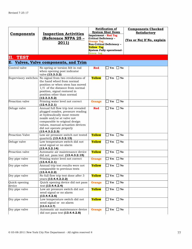
Revised 7-25-17
© 03-08-2011 New York City Fire Department - All rights reserved ®
77
Components
Inspection Activities (Reference NFPA 25 –
2011)
Notification of System Shut Down
Components Checked
Satisfactory
(Yes or No) If No, explain
Impairment - Red Tag
Critical Deficiency – Orange Tag Non-Critical Deficiency – Yellow Tag
System Fully operational- Green tag
II. TEST E. Valves, Valve components, and Trim
Control valve No spring or torsion felt in rod
when opening post indicator valve (13.3.3.2)
Red Yes No
Supervisory switches No signal from two revolutions of the hand wheel from normal position or when stem has moved 1/5 of the distance from normal position, signal restored in position other than normal
(12.3.3.5.2)
Yellow Yes No
Preaction valve Priming water level not correct
(12.4.3.2.1) Orange Yes No
Deluge valve Annual full flow trip test revealed plugged nozzles, pressure reading at hydraulically most remote nozzle and/or at valve not comparable to original design values, manual actuation devices did not operate properly
(13.4.3.2.2.3)
Red Yes No
Preaction Valve Low air pressure switch not tested quarterly (13.4.3.2.13)
Yellow Yes No
Deluge valve Low temperature switch did not send signal or no alarm
(13.4.3.2.14)
Yellow Yes No
Preaction valve Automatic air maintenance device did not pass test (13.4.3.2.15)
Yellow Yes No
Dry pipe valve Priming water level not correct
(13.4.4.2.1) Orange Yes No
Dry pipe valve Annual trip test results were not
comparable to previous tests
(13.4.4.2.2)
Yellow Yes No
Dry pipe valve No full flow trip test done after 3 years (13.4.4.2.2.2)
Yellow Yes No
Quick opening device
Quick opening device did not pass test (13.4.4.2.4)
Orange Yes No
Dry pipe valve Low air pressure switch did not send signal or no alarm
(13.4.4.2.6)
Yellow Yes No
Dry pipe valve Low temperature switch did not send signal or no alarm
(13.4.4.2.7)
Yellow Yes No
Dry pipe valve Automatic air maintenance device did not pass test (13.4.4.2.8)
Orange Yes No

Revised 7-25-17
© 03-08-2011 New York City Fire Department - All rights reserved ®
78
Components
Inspection Activities (Reference NFPA 25 –
2011)
Notification of System Shut Down
Components Checked
Satisfactory
(Yes or No) If No, explain
Impairment - Red Tag
Critical Deficiency – Orange Tag Non-Critical Deficiency – Yellow Tag
System Fully operational- Green tag
II. TEST E. Valves, Valve components, and Trim
Standpipe pressure
reducing control valves
No full flow test done after 5 years
or test results not comparable to previous results (13.5.1.2)
Yellow Yes No
Hose valves(Class I & Class III Standpipe system)
Annual test revealed valve leaking or difficult to operate
(13.5.6.2.1.1)
Orange Yes No
Hose valves Cap missing (13.5.2.1) Yellow Yes No
Hose valves Thread damaged (13.6.1.2) Orange Yes No
Hose valves Wheel handle broken or missing (not applied to NYCHA)
Orange Yes No
Backflow prevention assemblies
Did not pass forward flow test
(13.6.2.1) Red Yes No
Backflow prevention assemblies
No forward flow test done after one year (13.6.2.1)
Yellow Yes No

Revised 7-25-17
© 03-08-2011 New York City Fire Department - All rights reserved ®
79
PART 11: SIGNAGE REQUIREMENTS
All interior signage shall have a red background with minimum 1 inch high white letters. All exterior signage shall have a white background with minimum 1 inch high red letters.
(NYC Building Code and NYC FD Code) 11.1 Fire Department connection sign
11.2 Control valve sign
11.3 Stand Pipe System Shutoff sign
11.4 Fire Department connections serving a standpipe system sign Fire Department connections servicing a standpipe system shall be provide with
caps painted red, and shall have word
1111..44 Standpipe systems type sign
FIRE DEPARTMENT
CONNECTION
CONTROL VALVE
SHUTOFF FOR STANDPIPE SYSTEM LOCATED ______ FEET FROM THIS SIGN
STANDPIPE

Revised 7-25-17
© 03-08-2011 New York City Fire Department - All rights reserved ®
80
11.5 Supply Hose sign
Hose marked “SUPPLY HOSE” shall not be used at operating pressures exceeding 185 psi
11.6 Stairways without hose connections sign
Stairways without hose connections shall have a sign on the door to the stairway stating.
11.7 Fire Hose sign
If the hoses are installed in cabinets each cabinet should be labeled, indoor sign,
letters must be at least two inches high:
11.8 On Dry Standpipe with no Permanent Water Supply Sign
This system is usually used in a building that is not heated such as unoccupied buildings and parking garage structures. On this system a sign must be attached
to each of the hose outlets. It should read:
DRY STANDPIPE FOR FIRE DEPARTMENT
USE ONLY
SUPPLY HOSE
NO STANDPIPE CONNECTIONS IN
STAIRWAY
FIRE HOSE

Revised 7-25-17
© 03-08-2011 New York City Fire Department - All rights reserved ®
81
PPAARRTT 1122:: NNYYCC BBuuiillddiinngg LLOOCCAALL LLAAWW 5588 OOFF 22000099

Revised 7-25-17
© 03-08-2011 New York City Fire Department - All rights reserved ®
82
PART 13: Fire Department Code and Rules Chapter 9
1133..11 FFiirree DDeeppaarrttmmeenntt CCooddee SSeeccttiioonn 990055 Standpipe System
SECTION FC 905 STANDPIPE SYSTEMS
905.1 General. Standpipe systems shall be provided where required by the construction
codes, including the Building Code, this code or the rules. Fire hose threads used in connection with standpipe systems shall be approved by the commissioner. The location of fire department hose connections shall be approved by the commissioner. Standpipe
systems in buildings used for high-piled combustible storage shall be in accordance with FC Chapter 23.
905.1.1 Standpipe system operator. In buildings with a multi-zone standpipe system, such system shall be continuously under the personal supervision of a person holding a C of F, who shall be immediately available to assist the department in the operation of
such system. 905.2 Installation standards. Standpipe systems shall be installed in accordance with
the construction codes, including the Building Code. 905.3 through and including 905.6 Reserved. 905.7 Cabinets. Cabinets containing firefighting equipment, such as standpipes, fire
hose, portable fire extinguishers and water supply control valves, shall not be obstructed from use or obscured from view. 905.8 Reserved.
905.9 Valve supervision. Valves controlling water supplies shall be supervised in the open position so that a change in the normal position of the valve will generate a
supervisory signal at the central station required by FC Section 903.4. Where a fire alarm system is provided, a signal shall also be transmitted to the fire alarm system control panel.
Exceptions: 1. Valves to underground key or hub valves in roadway boxes provided by the
municipality or public utility do not require supervision. 2. Valves locked in the normal position and inspected as provided in this code in
buildings not equipped with a fire alarm system.
905.10 During construction. Standpipe systems required during construction, alteration and demolition operations shall be provided in accordance with Chapter 33 of the Building Code and FC Section 1413.
905.11 Reserved. 905.12 Maintenance. Standpipe systems shall be maintained, including all required
inspection, testing and servicing, in accordance with this section, FC Section 901.6 and NFPA 25.
905.12.1 Standpipe hydrostatic pressure and flow tests. Upon order of the
commissioner, but at least once every 5 years, the standpipe system shall be subjected to a hydrostatic pressure test and a flow test to demonstrate its suitability for
department use. These tests shall be conducted in compliance with the requirements

Revised 7-25-17
© 03-08-2011 New York City Fire Department - All rights reserved ®
83
of the rules and shall be conducted at the owner's risk, by his or her representative before a representative of the department.
1133..22 FFiirree DDeeppaarrttmmeenntt RRuulleess § 905-01 Standpipe System
§ 905-01 Standpipe System Pressure Reducing Devices
(a) Scope. This section sets forth requirements for standpipe system pressure reducing devices.
(b) Definitions. The following terms shall, for purposes of this section and used elsewhere in the rules, have the meanings shown herein:
Pressure reducing devices. Devices, including valves, installed in standpipe systems at or near hose outlet connections that act to limit both the static and dynamic water pressures downstream of the standpipe outlet valve. Pressure restrictors. Removable fittings or "SECO Type" valves that restrict flowing water pressures by reducing the available cross-sectional area of flow.
(c) General Provisions (1) Certificate of approval. Pressure reducing devices installed in a standpipe system
shall be of an approved type and for which a certificate of approval has been issued.
(d) Pressure Reducing Device Requirements. (1) Location and pressure markings. Each pressure reducing device shall be
permanently marked with the address of the premises in which it is installed, its floor location, and its designated pressure setting.
(2) Adjustments and reporting. Upon initial installation of a pressure reducing device, and at least once every three (3) years thereafter, a master fire
suppression contractor shall file an affidavit with the Department on behalf of the building owner attesting to the following:
(A) The building address and owner's name. (B) The floor location of all standpipe system pressure reducing devices and the inlet pressure (static and operating) of each device.
(C) The setting of each device and the corresponding discharge flow rate (gpm), discharge pressure (psig), and the maximum outlet static
pressure (psig). (D) The name, address, and master fire suppression contractor license
number of the person submitting the affidavit. (3) Flow testing. Upon order of the Commissioner, but at least once every three (3) years, standpipe systems with pressure reducing devices installed
shall be flow tested with a minimum actual flowing discharge of 250 gpm. These tests shall be conducted by a master fire suppression contractor who
shall provide the Department five (5) business days notice of the date and time of the test. The Department may witness these tests at its discretion.

Revised 7-25-17
© 03-08-2011 New York City Fire Department - All rights reserved ®
84
PART 14: LIST OF MAJOR CHANGES IN NEW S-13
1. ADJUSTED REFERENCES AND INFORMATION TO REFLECT NFPA 25 STANDARD,
2011 EDITION. NFPA REFERENCES HAVE BEEN ADDED TO THE REFERENCE GUIDE OF THE NEW STUDY MATERIAL.
2. Added on cover page: combined sprinkler/standpipe systems a valid S-12/S-15 is
also required.
3. NEW DEFINITIONS: ALARM NOTIFICATION APPLIANCE
ALARM SIGNAL AUTOMATIC BALL DRIP
CENTRAL STATION COMBINATION STANDPIPE AND SPRINKLER SYSTEM OS & Y VALVE
CURB VALVE CRITICAL DEFICIENCY NON CRITICAL DEFICIENCY
FIRE ALARM SYSTEM FIRE PROTECTION SYSTEM
FIRE PUMP, AUTOMATIC STANDPIPE FIRE PUMP, FOAM FIRE PUMP, LIMITED SERVICE
FIRE PUMP, SPECIAL SERVICE HYDRAULIC PLACARD
HYDRAULICALLY CALCULATED SYSTEMS IMPAIRMENT MAIN DRAIN
MICROBIOLOGICALLY INFLUENCES CORROSION PERSONAL SUPERVISION
4. Under 7.1 overview of standpipe systems, added information about multi-zone system.
5. Manual Wet Standpipe System section has been added from NFPA 14. 6. Changed Class III description to reflect NFPA 25 under 7.2 Classes of Standpipe
Systems.
7. Under fire pumps, new description of the centrifugal pump has been added. 8. Pump activation section has been altered to reflect changes.
9. Highlighted information in Part 10 (frequency table) is new.