fire officer training_aerial positioning
TRANSCRIPT
Module 4 –Aerial Operations Topic 1 – Positioning Apparatus
1/4/2017 Draft Page 1
Screen Name Content Reference M4T1_01 n/a Screen Text
Apparatus Positioning Effective apparatus positioning is critical to pumping operations, deployment of aerial apparatus and general incident control. You must position your apparatus in an area where it is most effective, while keeping the apparatus, yourself, and your crew out of harm’s way. Driver/operators must consider many factors when positioning their apparatus—including the fact that additional emergency vehicles may arrive after them.
Audio Production Elements Type Description Source
Video Fire scene with a shot from the running board of late arriving apparatus as it approaches a driver/operator standing in front of apparatus already positioned and directing driver with arm motions and speech to go left and support effort by positioning at the hydrant. Ambient noises and voice of driver/operator is in background to narrator’s voice.
See Pumper, Operations, Apparatus Positioning, Page 1 of 25
sfx ambient sound
audio narrator Branching (other than Next screen and Back) On Action Next M4T1_02 Back Module 4 Menu Notes

Module 4 –Aerial Operations Topic 1 – Positioning Apparatus
1/4/2017 Draft Page 2
Screen Name Content Reference M4T1_02 NFPA 5.2.4
Pumper Course M5T2-2 Screen Text This topic reviews what factors to consider when positioning fire apparatus for effective pumping operations. Specifically, we’ll look at these five areas of apparatus positioning:
<See Production Elements for screen text>
Select each bulleted item to learn more. Audio Production Elements Type Description Source
Graphic 1 Montage of pumper stills drawn from topic with these five hot items.
General guidelines for apparatus positioning Positioning for hydrants Drafting from a static water source Relay pumping operations Tandem pumping operations
Branching (other than Next screen and Back) On Action Next M4T1_25 Back M4T1_01
General guidelines for apparatus… M5T2_03 Positioning for hydrants M5T2_05
Drafting from a static water source M5T2_10 Relay pumping operations M5T2_12
Tandem pumping operations M5T2_20
Notes Next is active once each topic has been accessed.

Module 4 –Aerial Operations Topic 1 – Positioning Apparatus
1/4/2017 Draft Page 3
Screen Name Content Reference M4T1_03 NFPA 5.2.4
Pumper Course M5T2-3 Screen Text A fire apparatus has just responded to this incident. Most departments have standard procedures for positioning apparatus at an incident. However, standard procedures cannot possibly cover all situations. The ultimate decision of apparatus positioning rests with the fire officer in charge. Is the spot chosen for this apparatus a good one? Select the various components of the graphic. (Pop-up text 1) Hydrant Will this pumper need additional water? If so, the driver/operator should have laid a supply line as the pumper went up the driveway to the house. (Pop-up text 2) House Old structures can collapse during a fire. Always position your apparatus outside of the collapse zone of the structure—approximately equal to the height of the structure. (Pop-up text 3) Front Doors Always position your apparatus for effective rescue. This pumper is on the side opposite of the front doors and windows of the house. Is this the best spot? (Pop-up text 4) Power Lines Never park an apparatus under power lines that could interfere with the use of aerial devices or even fall on the apparatus during a fire incident. (Pop-up text 5) Apparatus What’s your method of attack? Will hand lines reach the seat of the fire? Are you within the effective range of aerial master streams, elevated platforms or turrets? Pop-up text 6) Trees Protect your apparatus! The fire could spread to surrounding trees. Can you easily reposition your apparatus if conditions change? Pop-up text 7) Wind and Slope Notice the slope around the house. For structural fires, try to park upwind and uphill from the fire. In this way, you avoid air-borne contaminants and runoff from the fire. Also, master streams directed into the structure will push fire back to the burning areas and NOT toward unburned areas. Pop-up text 8) Staging (Out on Main Street) Your apparatus may not be needed immediately. The fire officer in charge may assign you to a staging area where you will wait for an assignment.

Module 4 –Aerial Operations Topic 1 – Positioning Apparatus
1/4/2017 Draft Page 4
Audio Production Elements Type Description Source
Graphic 1 Fire incident with pumper stationed as shown in sketch. There are eight hot labels that have pop-up text:
Hydrant House Front Doors Power Lines Apparatus Trees Wind and Slope Staging (Out on Main Street)
See Pumper, Operations, Apparatus Positioning, Page 3 of 25
Branching (other than Next screen and Back) On Action Next M4T1_04KC
Back M4T1_02 Hydrant pop-up 1
House pop-up 2
Front doors pop-up 3 Power lines pop-up 4
Apparatus pop-up 5 Trees pop-up 6
Wind and slope pop-up 7 Staging (Out on Main… Pop-up 8
Notes Once all labels have been accessed, Next becomes active. Some edits to the Pumpers screen text have been made.

Module 4 –Aerial Operations Topic 1 – Positioning Apparatus
1/4/2017 Draft Page 5
Screen Name Content Reference/Screen Reference M4T1_04KC M4T1_03, NFPA 5.2.4 Screen Text Okay, let’s do a quick check. Here’s the same scene with the pumper. Given what you’ve learned, if you are the driver/operator, where would you position your apparatus? Select and drag the pumper to a new position.
Audio CA Well done! This position allows for effective rescue and, at the same time, protects your
apparatus. IA1 Nah! Remember, you want your apparatus to be upwind and upslope from a fire but
within effective range for rescues. Try again. IA2 No. The circle shows the best position. From here, the pumper is close to the front doors
and windows, uphill from the burning structure, and in a position to be easily repositioned.
Production Elements Type Description Source
Graphic 1 same as M5T2-3 (see programming notes below) with moveable apparatus icon
Pumper course
Audio Feedback narration Branching (other than Next screen and Back) On Action Next M4T1_05 Back M4T1_03 Notes CA = pumper should be moved to somewhere within the black circle (majority of pumper within the black circle for correct response). Some edits to the Pumpers screen and feedback text have been made.

Module 4 –Aerial Operations Topic 1 – Positioning Apparatus
1/4/2017 Draft Page 6
Screen Name Content Reference M4T1_05 NFPA 5.2.4
Pumper Course M5T2-8 Screen Text For the extended use of aerial apparatus like ladder pipes and master streams, you’ll need hydrants. How is apparatus positioning affected by forward and reverse lays from at a hydrant?
<See Production Elements for screen text> Select each graphic to learn more. Audio Production Elements Type Description Source
Three graphics
See Pumper. The three hot labels are:
Hydrant Guidelines Forward Lays Reverse Lays
See Pumper, Operations, Apparatus Positioning, Page 5 of 25
Branching (other than Next screen and Back) On Action Next M4T1_09KC
Back M4T1_04KC Hydrant Guidelines M4T1_06
Forward Lays M4T1_07 Reverse Lays M4T1_08
Notes Next is active only after all labels have been accessed. Some edits to the Pumpers screen text have been made.

Module 4 –Aerial Operations Topic 1 – Positioning Apparatus
1/4/2017 Draft Page 7
Screen Name Content Reference M4T1_06 NFPA 5.2.4
Pumper Course M5T2-9 Screen Text As a driver/operator, you should follow these basic hydrant guidelines. § Hard suction hoses should never be connected to a hydrant. Their couplings have
been known to fail, and they are designed for drafting from static sources, NOT for positive pressure conditions.
§ The best hose is a large diameter, soft intake hose between 10 and 50 feet in length. § Many districts require a gate valve on the smaller hydrant discharge before
connecting to the larger discharge. This allows additional hoses to be connected without interrupting the flow of the larger connection.
Audio Production Elements Type Description Source
Still 1 See Pumper Course See Pumper, Operations, Apparatus Positioning, Page 6 of 25
Still 2 See Pumper Course Still 3 See Pumper Course
Branching (other than Next screen and Back) On Action Next M4T1_05 Back M4T1_05
Notes No edits have been made to this screen
Module 4 –Aerial Operations Topic 1 – Positioning Apparatus
1/4/2017 Draft Page 8
Screen Name Content Reference M4T1_07 NFPA 5.2.4
Pumper Course M5T2-10 Screen Text In a forward lay, also called a straight or feeder lay, a pumper drops a supply line at the hydrant and moves forward to the fire. Advantages: § Allows the driver/operator to be at the fire scene and keep a visual on changing
circumstances § Forward lays using large diameter hose have virtually eliminated the need for reverse
lays due to the large quantity of water delivered § Forward lays keep the apparatus at the fire so that aerial devices are available for use. On forward lays, a four-way hydrant valve is usually installed to allow additional lines to be connected without interrupting the flow in the first line. Audio Production Elements Type Description Source
still 1 Shot of pumper moving slowly away from hydrant toward fire incident, a 4- to 5-inch hose connected to the hydrant and being laid down from the pumper. Hose should wrap around hydrant in a ¾-turn to protect hose. (SME: I don’t remember how important this fact is, but it’s not in the still of the Pumper course.
See Pumper, Operations, Apparatus Positioning, Page 6 of 25
Branching (other than Next screen and Back) On Action Next M4T1_05
Back M4T1_05
Notes Some edits to the Pumpers screen text have been made.
Module 4 –Aerial Operations Topic 1 – Positioning Apparatus
1/4/2017 Draft Page 9
Screen Name Content Reference M4T1_08 NFPA 5.2.4
Pumper Course M5T2-11 Screen Text In a reverse lay, a pumper lays a supply line from the fire incident to the hydrant. Reverse lays have certain advantages and disadvantages. Advantages: § Allows the driver/operator to evaluate the fire and then make appropriate hydrant
connections § The pumper can stay at the hydrant to boost hydrant pressure or be used in relay
operations Disadvantages: § If only one pumper is responding, you need to drop critical equipment at the fire scene
before doing the reverse lay § Keeps the driver/operator at the hydrant instead of at the fire scene Audio Production Elements Type Description Source
still 1 Shot of pumper laying down a supply line as it moves away from fire incident toward distant hydrant. Add an arrow to show the direction of travel.
See Pumper, Operations, Apparatus Positioning, Page 7 of 25
Branching (other than Next screen and Back) On Action Next M4T1_05 Back M4T1_05
Notes

Module 4 –Aerial Operations Topic 1 – Positioning Apparatus
1/4/2017 Draft Page 10
Screen Name Content Reference/Screen Reference M4T1_09KC M4T1_07/08, NFPA 5.2.4 Screen Text Do you understand forward and reverse lays? Select a number in the right column and drag it to the matching response on the left OR type the number of the phrase on the right that matches the filled circle response on the left. Select Judge when you are done. __ Hose is laid from the fire incident to the hydrant 1. forward lay __ Usually used with a four-way hydrant valve 2. reverse lay __ Keeps the driver/operator at the hydrant __ Keeps the pumper at the hydrant __ Hose is laid from the hydrant to the fire incident __ Critical equipment must be unloaded first at the fire incident
Audio CA Way to go! You understand both approaches! IA1 Hold those fire horses! Try again. IA2 No. Take a look at the correct answers. Production Elements Type Description Source Audio Feedback narration Branching (other than Next screen and Back) On Action Next M4T1_02 Back M4T1_05 Notes CA = 2, 1, 2, 2, 1, 2 Some edits to the Pumpers screen and feedback text have been made.
Module 4 –Aerial Operations Topic 1 – Positioning Apparatus
1/4/2017 Draft Page 11
Screen Name Content Reference M4T1_10 NFPA 5.2.4
Pumper Course M5T2-13 Screen Text If you have two crew members with a master stream on an elevated platform, you want to make sure of your water supply. You never know when you might need to draw from a static water source. Here’s a four-step procedure for drafting from a static water source, such as a pond, stream, or cistern.
<See Production Elements for screen text> Select each step to learn more. (Pop-up text for still 1) Stop Short Stop the pumper short of a static water source selected for minimum lift (primary consideration) and minimum hose length (maximum efficiency). Both of these allow for easier pumping. (pop-up text for still 2) Make Your Connections Connect a hard suction intake hose to the pump and a strainer to the hose. This is easier and safer to do when you’re standing on firm ground! (pop-up text for still 3) Move into Position Move your fire apparatus carefully into a drafting position. If possible, keep the apparatus on a paved or firm grassy surface. (pop-up text for still 4) Place hose in water and secure Place the hose and the strainer into the water. Keep the strainer off the bottom by using a rope tied to the end of the hose. Secure the rope to the bumper of the apparatus or to another stable object. (pop-up text 5) Caution icon Take care! Suction may not occur if any section of the hard intake hose is higher than the intake valve of the pump. Position your apparatus accordingly. Audio Production Elements Type Description Source
Graphic 1 There are four hot labels on the screen plus the Caution:
Stop short Make your connections Move into position Place hose in water and secure

Module 4 –Aerial Operations Topic 1 – Positioning Apparatus
1/4/2017 Draft Page 12
Graphic 2 Caution icon Still 1 Apparatus is approaching lake (first frame of video 1)
See Pumper, Operations, Apparatus Positioning, Page 10 of 25
Still 2 ff connecting hard suction intake hose to pump (first frame of video 2)
Still 3 Apparatus moving carefully into drafting position with ff carrying hose and strainer toward lake (first frame of video 3)
Still 4 ff placing hose and strainer in water with the aid of a rope tied to end of hose (first frame of video 4)
Video 1 Thumbnail video clip of apparatus approaching lake Video 2 Thumbnail video clip of ff connecting intake hose to pump
and strainer to hose (abbreviate sequence as necessary). Have rope already tied to strainer when it is connected to hose.
Video 3 Thumbnail video clip of apparatus moving into position Video 4 Thumbnail video clip of ff placing hose and strainer into
water with aid of rope, and then securing rope to bumper to pumper.
sfx Ambient sound Branching (other than Next screen and Back) On Action Next M4T1_11KC Back M4T1_02 Still 1 Video 1, pop-up text 1 Still 2 Video 2, pop-up text 2 Still 3 Video 3, pop-up text 3 Still 4 Video 4, pop-up text 4 Caution icon Pop-up text 5 Notes Four stills are labeled (see screen text), video runs off of each. When each is selected, run video and display appropriate text. Some edits to the Pumpers screen text have been made.
Module 4 –Aerial Operations Topic 1 – Positioning Apparatus
1/4/2017 Draft Page 13
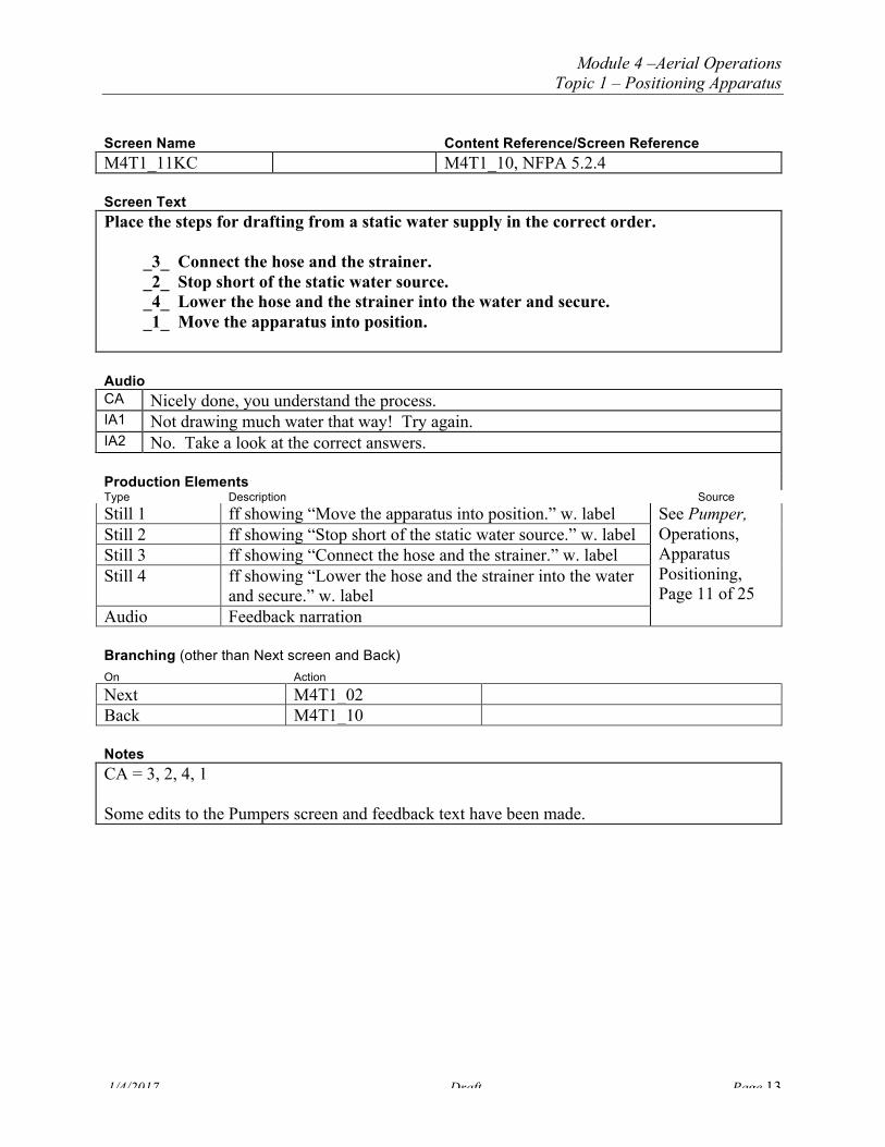
Screen Name Content Reference/Screen Reference M4T1_11KC M4T1_10, NFPA 5.2.4 Screen Text Place the steps for drafting from a static water supply in the correct order.
_3_ Connect the hose and the strainer. _2_ Stop short of the static water source. _4_ Lower the hose and the strainer into the water and secure. _1_ Move the apparatus into position.
Audio CA Nicely done, you understand the process. IA1 Not drawing much water that way! Try again. IA2 No. Take a look at the correct answers. Production Elements Type Description Source Still 1 ff showing “Move the apparatus into position.” w. label See Pumper,
Operations, Apparatus Positioning, Page 11 of 25
Still 2 ff showing “Stop short of the static water source.” w. label Still 3 ff showing “Connect the hose and the strainer.” w. label Still 4 ff showing “Lower the hose and the strainer into the water
and secure.” w. label Audio Feedback narration Branching (other than Next screen and Back) On Action Next M4T1_02 Back M4T1_10 Notes CA = 3, 2, 4, 1 Some edits to the Pumpers screen and feedback text have been made.

Module 4 –Aerial Operations Topic 1 – Positioning Apparatus
1/4/2017 Draft Page 14
Screen Name Content Reference M4T1_12 NFPA 5.2.4
Pumper Course M5T2-15 Screen Text A relay pumping operation is used when the water source is remote from the fire incident. A source pumper is stationed at the water source and one or more additional pumpers “relay” the water through their pumps to the apparatus at the fire scene. Pass your cursor over each item in the relay chain to see what it is. Then, select each item to learn more. (Pop-up text 1) Source Pumper The design of a relay pumping operation is driven by the desired flow at the fire scene. A supplying pumper must provide the next-in-line apparatus with at least 20 psi of intake pressure. This reduces the possibility of damage to the apparatus pumping system. The driver/operator of the source pumper must communicate the pumping capacity to the Incident Commander, along with any hose and pressure changes during the operation. If available, a fixed or portable pump can substitute for the source pumper.
(Pop-up text 2) First Relay Pumper Since there can be sudden pressure fluctuations in relay operations, relay pumpers must have intake pressure relief valves (if available) set at 10 psi above the discharge pressure of the previous pumper to dump water as needed. Select the underlined text to learn more. (Pop-up text 3) Intake pressure relief valves These valves are used to reduce the potential for damage to the pump or hoselines due to water hammer, which is caused by pressure fluctuations. A pressure relief valve can be part of the pump itself or screwed onto the pump intake connection. Each driver/ operator must ensure that flow psi never exceeds rated pump capacity and communicate any problems to the Incident Commander. (Pop-up text 4) Second Relay Pumper Relay pumpers must have a method of bleeding air from hoses being charged with water. This may be done through opening unused discharge valves or through the use of a built-in bleeder valve. Select the underlined text for more information. (Pop-up text 5) bleeder valve A bleeder valve can discharge large quantities of air when the line is being charged with water. It’s important for the driver/operator to monitor the pressure control devices and bleeder valves on pumps and hose connections. (Pop-up text 6) Incident Commander The Incident Commander must look at the fire attack to determine the desired nozzle

Module 4 –Aerial Operations Topic 1 – Positioning Apparatus
1/4/2017 Draft Page 15
pressure needed at the fire scene. Factors that can determine desired pressure include the use of elevated master streams, hose type, hose size, pump discharge pressure, and elevation changes from the water source. Based on these factors, the commander must design a system that can deliver this pressure. (Pop-up text 7) Attack pumper The attack pumper can only fight the fire for a limited amount of time (depending on the size of its water tank and the amount of water being discharged). Keep in mind that establishing a relay operation is not a quick process, and you may run out of water before a permanent resupply is in place.
Audio Production Elements Type Description Source
Graphic 1 Sketch shown above. Source pumper is drafting from lake. Water hoses connect four pumpers with the Incident Commander near the attack pumper. Two attack lines go into the burning house. There are five primary hot labels in this graphic that have supporting pop-up text:
Source Pumper First Relay Pumper Second Relay Pumper Incident Commander Attack Pumper
In addition, within two of these pop-ups, there is an additional pop-up with a supporting still: (within First Relay Pumper) Intake pressure relief valves (within Second Relay Pumper) Bleeder valve
See Pumper, Operations, Apparatus Positioning, Page 12 of 25
Still 1 Still of intake pressure relief valve on pumper (similar to IFSTA, p. 313, fig. 13.7) to accompany pop-up text for second relay pumper.
Still 2 Still of bleeder valve to accompany text for Second Relay Pumper pop-up.
New
Branching (other than Next screen and Back) On Action Next M4T1_13 Back M4T1_02
Source pumper Pop-up 1 First relay pumper Pop-up 2

Module 4 –Aerial Operations Topic 1 – Positioning Apparatus
1/4/2017 Draft Page 16
(within First Relay Pumper) Intake pressure relief valves
Pop-up 3/still 1
Second relay pumper Pop-up 4 (Within Second Relay Pumper) Bleeder valve Pop-up 5/still 2
Incident Commander Pop-up 6
Attack pumper Pop-up 7 Notes Use existing programming notes in Pumper, Operations, Apparatus Positioning, Page 12 of 25 Some edits to the Pumpers screen text have been made.

Module 4 –Aerial Operations Topic 1 – Positioning Apparatus
1/4/2017 Draft Page 17
Screen Name Content Reference M4T1_13 NFPA 5.2.4
Pumper Course M5T2-16 Screen Text There are two ways to set up a relay pumping operation:
<See Production Elements for screen text> The Constant Pressure Relay method is more common. Select each item to learn more. Audio Production Elements Type Description Source
Graphic 1 Modified graphic from M4T1_12 (M5T2-15 in old Pumper course) with no pumpers, driver/operators or lines. There are two hot topics:
Constant Pressure Relay method Maximum Distance Relay method
See Pumper, Operations, Apparatus Positioning, Page 13 of 25
Branching (other than Next screen and Back) On Action Next M4T1_02 Back M4T1_12
Constant pressure M4T1_14 Maximum distance M4T1_17
Notes I have added initial caps to the names of these two methods. I made this screen a decision point so students return to this screen to select the second relay method. It was confusing to flow from one method to the second without acknowledging that the discussion of the first method had ended.

Module 4 –Aerial Operations Topic 1 – Positioning Apparatus
1/4/2017 Draft Page 18
Screen Name Content Reference M4T1_14 NFPA 5.2.4
Pumper Course M5T2-16a Screen Text The Constant Pressure Relay method is the simpler of the two relay methods. It has some advantages and disadvantages. Advantages:
• The length of hose and the pump pressure is predetermined. The driver/operator does not need to await specific instructions.
• Eliminates complex pump calculations. • Driver/operators in the relay only have to maintain one constant pressure. • Reduces radio traffic and confusion.
Disadvantages: If small diameter supply lines (2 ½- or 3-inch) are used then they:
• Limit the total gallons available per minute (gpm) • May not provide adequate pressure due to high friction loss • Limit the distance between apparatus to approximately 750 feet
Audio Production Elements Type Description Source
Still Shot from relay pumper to attack pumper See Pumper, Operations, Apparatus Positioning, Page 14 of 25
Branching (other than Next screen and Back) On Action Next M4T1_15 Back M4T1_13
Notes Some edits to the Pumpers screen text have been made.

Module 4 –Aerial Operations Topic 1 – Positioning Apparatus
1/4/2017 Draft Page 19
Screen Name Content Reference M4T1_15 NFPA 5.2.4
Pumper Course M5T2-16b Screen Text Here is a constant pressure relay pumping operation. Pass your cursor over each item to see what it is. Then, select each item in the relay chain to learn more. (Pop-up text 1 for source pumper) In a Constant Pressure Relay method, the source pumper and all relay pumpers pump water at a constant 175 psi using a single hose size. It’s crucial to have continual communication between all parties in order to ensure correct pressure and to update each other on changing circumstances.
(Pop-up text 2 for relay pumper) It’s important that each pumper has an automatic pressure control valve to control accumulative pressure changes. As in any relay pumping operation, it is important for each driver/operator to ensure that flow psi never exceeds rated pump capacity. (Pop-up text 3 for attack pumper) The attack pumper uses an open discharge or secured waste line to handle excess pressure. When shutting down a constant pressure relay, start with the attack pumper and work backwards to the source pumper.
Audio Production Elements Type Description Source
Graphic 1 See Pumper course for existing graphic. It would be nice to have the attack apparatus have an aerial device on it.
See Pumper, Operations, Apparatus Positioning, Page 15 of 25
Branching (other than Next screen and Back) On Action Next M4T1_16 Back M4T1_14
Source pumper Pop-up text 1 Relay pumper Pop-up text 2
Attack pumper Pop-up text 3 Notes Student rolls the three hot items to see their labels and then selects each one for pop-up text. Next is inactive until all three hot items are accessed. Some edits to the Pumpers screen text have been made.

Module 4 –Aerial Operations Topic 1 – Positioning Apparatus
1/4/2017 Draft Page 20
Screen Name Content Reference M4T1_16 NFPA 5.2.4
Pumper Course M5T2-17 Screen Text Here are the seven steps for creating a Constant Pressure Relay. Select each number in order to learn more. (Pop-up text 1 for box #1) Station the largest capacity pumper at the water source and begin hook-up. (Pop-up text 2 for box #2) Lay out hose according to department policy and make all connections.
(Pop-up text 3 for box #3) For all pumpers except the source pumper, if there is NO intake pressure relief valve, open the discharge valve on the dump line. Select the underlined text to learn more.
(Pop-up text 4 for “dump line”) A dump line may be either an open discharge valve or another hoseline not currently in use. It is used to relieve excess water pressure (psi) when the apparatus intake exceeds 50 psi in a relay operation. (Pop-up text 5 for box #4) Have the source pumper start pumping water at 175 psi.
(Pop-up text 6 for box #5) Have each relay pumper close its discharge valve once a steady flow of water reaches it, then advance the throttle to 175 psi.
(Pop-up text 7 for box #6) Once a pumper is on-line, have that driver/operator set the intake pressure regulating device (if available) to 10 psi above the input pressure.
(Pop-up text 8 for box #7) Have the driver/operator of the attack pumper adjust discharge pressure to supply attack lines.
Audio

Module 4 –Aerial Operations Topic 1 – Positioning Apparatus
1/4/2017 Draft Page 21
Production Elements Type Description Source
Graphic 1 Use same graphic as in Pumper Course, Operations, Apparatus Positioning, Page 16 of 25.
See Pumper, Operations, Apparatus Positioning, Page 16 of 25
Branching (other than Next screen and Back) On Action Next M4T1_13 Back M4T1_15
#1 box Pop-up 1 #2 box Pop-up 2
#3 box Pop-up 3 “Dump line” (text in pop-up 3) Pop-up 4
#4 box Pop-up 5
#5 box Pop-up 6 #6 box Pop-up 7
#7 box Pop-up 8 Notes SME:Fortheyellowhighlightedtextabove,itappearsthatintakepressureshouldnotexceed50psianddischargepressureshouldbeheldat175psiinaconstantpressurerelay.Isthiscorrect?

Module 4 –Aerial Operations Topic 1 – Positioning Apparatus
1/4/2017 Draft Page 22
Screen Name Content Reference M4T1_17 NFPA 5.2.4
Pumper Course M5T2-18a Screen Text The Maximum Distance Relay method uses a calculations table. First you enter the required flow in gpm. Then you enter the hose diameter you have available. The table then shows you the maximum length of hose you can use to deliver this gpm (see next screen). Advantage: • Gives you greater flexibility for establishing the relay operation by allowing longer
hose lays than the constant pressure relay method set up. Disadvantages: • Maximum hose distance must be calculated based on gpm required and hose diameter. • Requires greater communication between the driver/operators on the relay. • Number of apparatus may vary due to the actual amount of hose carried on each
apparatus. • It requires the use of a calculations table. Audio Production Elements Type Description Source
Graphic D/O using the table from IFSTA, p. 317, Table 13.3 (on next screen) and a radio to communicate to another D/O.
Branching (other than Next screen and Back) On Action Next M4T1_18
Back M4T1_13 Notes Some edits to the Pumpers screen text have been made.
Module 4 –Aerial Operations Topic 1 – Positioning Apparatus
1/4/2017 Draft Page 23
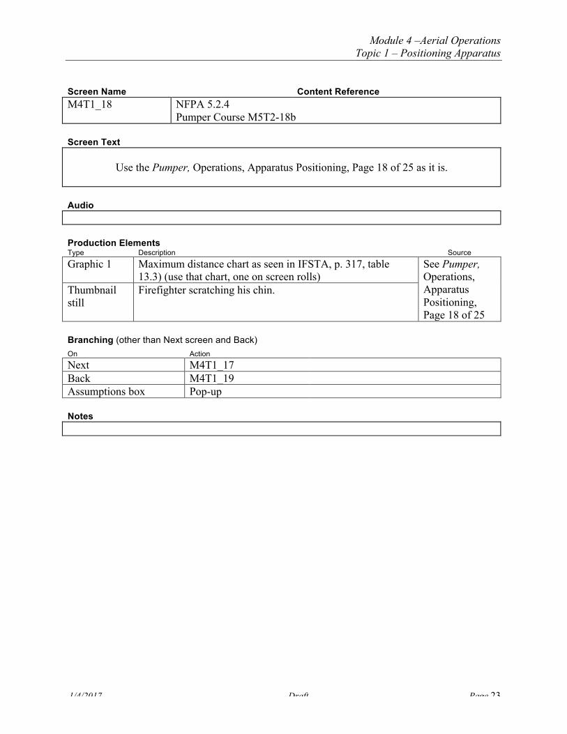
Screen Name Content Reference M4T1_18 NFPA 5.2.4
Pumper Course M5T2-18b Screen Text
Use the Pumper, Operations, Apparatus Positioning, Page 18 of 25 as it is. Audio Production Elements Type Description Source
Graphic 1 Maximum distance chart as seen in IFSTA, p. 317, table 13.3) (use that chart, one on screen rolls)
See Pumper, Operations, Apparatus Positioning, Page 18 of 25
Thumbnail still
Firefighter scratching his chin.
Branching (other than Next screen and Back) On Action Next M4T1_17
Back M4T1_19 Assumptions box Pop-up
Notes

Module 4 –Aerial Operations Topic 1 – Positioning Apparatus
1/4/2017 Draft Page 24
Screen Name Content Reference M4T1_19 NFPA 5.2.4
Pumper Course M5T2-19 Screen Text Use the Pumper, Operations, Apparatus Positioning, Page 19 of 25 as it is with one change: On
the chart, circle the “825” to make it obvious to the user. Audio Production Elements Type Description Source
Graphic 1 Screen in quadrants (see description below) See Pumper, Operations, Apparatus Positioning, Page 19 of 25
Graphic 2 Maximum distance chart as seen in IFSTA, p. 317, table 13.3, same as in Pumper Course M5T2-18b
Graphic 3 Same as Graphic 2 in Pumper Course M5T2-18b
Branching (other than Next screen and Back) On Action Next M4T1_02 Back M4T1_18 Assumptions box Small graphic for assumptions box—ff
scratching head w/label “Assumptions” Same as M4T1_18
Notes Same Programming Notes as in Pumper storyboards, M5T2-19

Module 4 –Aerial Operations Topic 1 – Positioning Apparatus
1/4/2017 Draft Page 25
Screen Name Content Reference M4T1_20 NFPA 5.2.4
Pumper Course M5T2-20 Screen Text A tandem pumping operation is a modified version of a relay pumping operation. It is used when the pressure needed is higher than a single engine is capable of supplying, such as high rise sprinklers, standpipe systems, or very long hose layouts. The first pumper is positioned at a hydrant. A second pumper is placed within 300 feet of the first pumper to boost the pressure in the first pumper’s supply line. These pumpers are operating in series. Select the graphic to see how the pumpers are connected. (Pop-up text 2) Caution Take care NOT to supply a pressure greater than the rated pressure of the hose or pump. Audio Production Elements Type Description Source
Still 1 Tandem operation at hydrant with two pumpers in series, similar to IFSTA p. 89, figure 5.44. This still is hot
See Pumper, Operations, Apparatus Positioning, Page 20 of 25
Still 2 Pop-up still over Still 1. This shows the discharge port on one apparatus and the intake port on the other. Have Graphic 1 label overlay it.
Graphic 1 Text overlays Still 2, Discharge to Intake Graphic 2 Caution icon Branching (other than Next screen and Back) On Action Next M4T1_21 Back M4T1_02
Still 1 Still 2/Graphic 1 Caution Pop-up text 2
Notes Still 2 is not the best shot in the world of the discharge and intake ports of two apparatus. Slight edits on screen text. Some edits to the Pumpers screen text have been made.

Module 4 –Aerial Operations Topic 1 – Positioning Apparatus
1/4/2017 Draft Page 26
Screen Name Content Reference M4T1_21 NFPA 5.2.4
Pumper Course M5T2-20b Screen Text In comparison to a tandem pumping operation, a dual pumping operation requires the pumpers to be parked side-by-side and connected intake-to-intake. This type of operation allows one strong hydrant to supply two pumpers. The second pumper uses the excess water from the hydrant that is not being used by the first pumper. This allows each pumper to perform a separate operation from the same water source. Audio Production Elements Type Description Source
Still 1 See Pumper Course, Operations, Apparatus Positioning, Page 21 of 25. Recommend some textual changes and a reshoot of Still 1
Branching (other than Next screen and Back) On Action Next M4T1_22KC
Back M4T1_20 Notes This is a little confusing to me. Does the hoseline split and send some water to each intake of each pumper? The still does not clarify how hoselines are connected. I think we could keep the still but add an overlapping graphic of how the hoselines are connected from the hydrant to the two pumpers. Also, if we are going to reshoot this, I think we should put some aerial devices on the pumpers and show how tandem pumping operations can be used to support a master stream on an elevated platform.

Module 4 –Aerial Operations Topic 1 – Positioning Apparatus
1/4/2017 Draft Page 27
Screen Name Content Reference/Screen Reference M4T1_22KC NFPA 5.2.4, M4T1_19 Screen Text Now let’s see if you can set up a maximum distance relay pumping operation. There is a lake 2,100 feet from the fire. You have four pumpers available, each with 1,200 feet of 4-inch hose, and you need 750 gpm at the fire scene. Drag and drop each needed pumper onto the relay line. Make sure that each pumper is properly located. Select the Maximum Distance Chart icon to review the chart. Audio CA Excellent work! You properly determined that you needed three engines and you did not
exceed the maximum allowable distance for 4-inch hose flowing 750 gpm, which is 1,450 feet.
IA1 Remember to divide 2,100 by 1,450 from the chart, and determine the maximum allowable distance for your hose layout. Try again.
IA2 No. The maximum allowable distance between pumpers is 1,450 feet. Since the total distance is 2,100 feet, divide 2,100 by 1,450 = 1.5. Then 1.5 + 1.0 = 2.5. Rounding up you need 3 pumpers--one stationed on each end and one in the middle of the 2,100 feet.
Production Elements Type Description Source
Audio Feedback narration Use these production elements as is from the Pumper Course
Graphic 1 Graphic similar to M5T2-15 (in Pumper Course) with lake, use gradients of 100 feet all the way up to 2100.
Graphic 2 Icon “Maximum Distance Chart” Graphic 3 Maximum distance chart as shown in M5T2-18b (Pumper
Course) Graphic 4 Pumper for click and drag within Graphic 1 Audio Narrator feedback Branching (other than Next screen and Back) On Action Next M4T1_23KC Back M4T1_21 Notes CA = user should place three pumpers on the relay line, one at the lake, one at the fire, and one somewhere between the 600 and the 1400 foot marks on the line.

Module 4 –Aerial Operations Topic 1 – Positioning Apparatus
1/4/2017 Draft Page 28
Screen Name Content Reference/Screen Reference M4T1_23KC M4T1_16, NFPA 5.2.4 Screen Text Here’s another one for you. When a relay pumping operation is being set up, after the source pumper starts pumping water, the next pumper in the relay should first:
a. close its discharge valve on the dump line. b. set its pump throttle at 175 psi. c. wait until it gets a steady flow of water. d. open its discharge valve on the dump line.
Audio CA Well done! IA1 No, what is the first thing the next pumper in the relay should do? Try again. IA2 No. The next pumper needs to get a steady flow of water and then slowly close its own
discharge valve on the dump line so that it can transfer flow to the next pumper in the relay.
Production Elements Type Description Source
Audio Feedback narration Branching (other than Next screen and Back) On Action Next M4T1_24KC Back M4T1_22KC Notes CA = c Some edits to the Pumpers screen text have been made.

Module 4 –Aerial Operations Topic 1 – Positioning Apparatus
1/4/2017 Draft Page 29
Screen Name Content Reference/Screen Reference M4T1_24KC M4T1_20/21, NFPA 5.2.4 Screen Text When comparing dual pumping operations to tandem pumping operations, which TWO of the following statements are correct?
a. Dual operations have the source pumper discharging to the intake of the receiving pumper.
b. Dual operations have the apparatus connected intake-to-intake. c. Tandem operations have the source pumper discharging to the intake of the
receiving pumper. d. Tandem operations have the apparatus connected intake-to-intake.
Audio CA Excellent! IA1 Nope. Try again. IA2 That’s incorrect. Dual operations have the apparatus connected intake-to-intake, while
tandem operations have the source pumper discharging to the intake of the receiving pumper.
Production Elements Type Description Source
Audio Feedback narration Branching (other than Next screen and Back) On Action Next M4T1_02 Back M4T1_23KC Notes CA = b, c Some edits to the Pumpers screen text have been made.

Module 4 –Aerial Operations Topic 1 – Positioning Apparatus
1/4/2017 Draft Page 30
Screen Name Content Reference M4T1_25 N/A Screen Text
Positioning Apparatus Apparatus positioning plays an important role in effective fire fighting. You need a good grasp of apparatus positioning strategies to meet a variety of needs—from positioning apparatus for aerial operations to complex relay pumping operations.
In this topic, we looked at: • General guidelines for apparatus positioning • Positioning for hydrants • Drafting from a static water source • Relay pumping operations • Tandem pumping operations Select any topic to review or Next to move on to the Challenge Review questions. With the information in this topic you will be prepared to act quickly when figuring out the most effective strategies for positioning apparatus at the fire scene.
Audio Production Elements Type Description Source
Graphic Montage of images used throughout the topic Audio narrator Branching (other than Next screen and Back) On Action Next M4- topic menu Back M4T1_02
General guidelines for apparatus… M5T2_03 Positioning for hydrants M5T2_05
Drafting from a static water source M5T2_10 Relay pumping operations M5T2_12
Tandem pumping operations M5T2_20
Notes Some edits to the Pumpers screen text have been made.

Module 4 –Aerial Operations Topic 1 – Positioning Apparatus
1/4/2017 Draft Page 31
Challenge Review Questions Module 4, Topic 1

Module 4 –Aerial Operations Topic 1 – Positioning Apparatus
1/4/2017 Draft Page 32
Final Test Questions Module 4, Topic 1