first flight: velocity rg elite in this issue · vukos’ first flight: velocity rg elite judy and...
TRANSCRIPT

Velocity Views14th Quarter 1996
In this issueFirst Flight ........................1
John Vukos’ new VelocityRG Elite
Let’s Be Constructive ......2The right way to call whenyou find an error in themanual
Factory News ...................3Builder notices, Franklinengine update, and othernews from the Swings
Safety Corner ...................5Accident & IncidentReports and MaintenanceService Difficulties.
Short Circuit .....................7Electrical, instrument, andavionics related tips fromMartin Hadley
Factory KPCs ...................9Kit plans changes to keepyour manual up-to-date
2nd Florida Fly-in...........10Plan on attending the fac-tory sponsored fly-in to beheld Nov 2-3 in historic StAugustine, Florida
Builder Forum ................12Tips, information & letters
Views from the West......21News from Velocity’s westcoast service center
Buy Sell or Trade ...........22Renewal Invoice.............23
Volume 8
Continued on page 2
Vukos’ First Flight: Velocity RG Elite
Judy and I met John and GailVukos two years ago at CentralStates Association’s “Rough River”Fly-in in Kentucky. We both flewLong EZs, but deep down wishedwe had Velocitys. When JimmyDallas landed that night in hisVelocity, we both spent time admir-ing all the advantages Velocity hadto offer. Within a few short months,both John and I had put downdeposits for Velocity kits. We havekept in close contact since then, andI am looking forward to hopefullyseeing John’s new pride and joy atthe November Florida fly-in.
It took John only a year and ahalf to complete his Velocity. I e-mailed him and asked John toanswer a few basic questions for usVelocitites still slaving away on ourprojects. The following is John’sresponse.
Rick
My first flight was June 8th,1996. I started my project on Jan. 1st1995. It took me 1550 hours to com-plete. I had built a Long EZ before, sothat experience helped. I built myVelocity to fly, not as a show plane. Ican be proud of it, but it isn’tdetailed like some that have everyphillips head screw oriented thesame.
The first flight was fairlyuneventful. I was most concernedabout not having enough pitch downtrim. I needed to reposition the pitchtrim spring. Otherwise, it was justgetting used to the heavier feel goingfrom a Long EZ to a Velocity. So far,top speed is 184 kt true at 3000 ft2760 rpm. I cruise at 10,000 ft at 2600rpm and 170 kt true, burning about 8gph.
I put in a B&C 60A alternator,Skytec lightweight starter,Strikefinder, RMI uEncoder and

Velocity Views 2 Volume 8
First Flightcontinued from page 1
uMonitor, Navaid wingleveler, ADCscreen oil filter; used Bob Nuckolls’schematics for wiring, B&C automo-tive fuse blocks and busses, temperfoam seat cushions; left off bottomwinglets, ran polypropylene tubesdown the keel to run the brake linesin (for easy replacement); made thenose access door bigger; installed thelighter bellville washers and nylocnut for the shimmy damper; and didthe internal rudder belhorns. I usedDupont Basecoat/Clearcoat paint -very easy to use. Performance 3blade 65x75. Engine is an IO360C1C6 out of an Arrow. CHT’s runabout 180 C and fairly even after a lit-tle adjustment with the inlet baffleramps. Oil temps run 100 to 105 C,only got to 112 C in a quick climb to12,000 (redline is 118 C).
As far as do’s and don’ts - thehardest part was working from thesketchy instructions in the old manu-al; and it’s still going to be hard withthe new manual - it’s organized bet-ter, but still needs improvement tomake the instructions clearer. Thebuilding process went fairly well,only a glitch now and then because Iwas so close behind the prototypebuilding. I would not use the fuelcaps provided with the kit - cannotget them to seal properly even withadjustment and lubrication. I’mthinking about ripping them out andputting in the newer ones. I wouldn’tuse the throttle and mixture cablesfrom the factory, I’d get some with avernier adjustment. I didn’t usephillips head screws for cowl, rudderhinge, etc. Instead I used hex head SSsocket (available from McmasterCarr). I had to weld some 1/4” barstock onto the door handles becausethe originals are too flimsy when theweather stripping is uncompressed(people will see what I mean).
My longest flight so far was a tripfrom Oshkosh to Winterhaven,Florida. Everything ran well, no realcomplaints except for fuel leaking outof the fuel caps. I would really rec-ommend the Navaid wingleveler andthe Strikefinder for long cross coun-try trips - they both work great.
John Vukos
John and Gail Vukos, proudly pose before their beautiful new Velocity RG Elite
John is all smiles just moments afterengine shut down from his first flight
John’s impressive panel includes aStrikefinder, RMI, and auto pilot
Continued on next page
L e t ’s be construc-tive when wec o m p l a i n !
I have been sensing a bit of fric-tion between a few builders and thefactory of late about things like themanuals or the tapes. If this does notapply to you, I apologize for preach-ing to the choir!
Prior to addressing the manuals,we must all realize that we each havea vested interest in seeing VelocityInc. staying successful and profitable.Remember what happened to thevalue of the Long EZ when Rutanfiled for bankruptcy protection dueto the threat of a law suit? A strongVelocity Inc. run by the Swingsmeans we continue to get strongbuilder support, new advances, anda continued market for our unfin-ished kits or flying Velocitys, shouldwe decide to sell. Therefore, as abuilder, we each have a unique part-nership with the Swings to makethings right!
As a builder, I want a perfectmanual. But in the real world, thereis no perfect manual. So what actionshould I take when I find a mistake,or a section that needs clarification,or perhaps an improved drawing?Do I:A) Call the factory to complain andmake destructive comments aboutthe manual? orB) Call the factory, point out a prob-lem I found, and make a constructivesuggestion as to how I think it can befixed.
Obviously, (I hope ), option Bwill get the best results and keep usall friends. Those very few buildersthat chose option A end up puttingthe Swings on the defensive andmake it very difficult for the rest ofus when we call to suggest a changein the manual.
Jeff Baker is now the factory’skey man in coordinating KPCs andimproving the manual on an on-going basis. Each of us builders has aduty to get the manual as close to
Velocity Views34th Quarter 1996
by Duane & Scott Swing
Builder NoticesThe 173 FG and 173 FG Elite use
a larger nose fork and tire assembly.We found that the steel spacers thatcenter the wheel in the fork are toosmall. This allows side movementwhich is not allowed. We made thechange after the last newsletter wassent out so the new kits all have thecorrect spacers. Check your set upand let us know if you need thelonger ones. The right length isapproximately 29/32”.
The new style overcenter linkagehas fork ends that are like tabs weld-ed on the front and back sides of thetubing. The older style had a “U”shaped fork end welded all aroundthe end. Ever since this new designwas developed, for ease of fabrica-
tion, we have suspected that it maybe a little weaker at the ends. Thedesigner thought that it would becomparable to the other. Not believ-ing that, we tested the linkage andfound the fork ends to buckle at 6000to 7000 lbs. When testing the olddesign, it went up to 8000 to 9000lbs. Even though 3 1/2 tons per sideshould be adequate, we know of twoor three linkages that had their forkends buckle under a hard landing.Knowing this we added gusetts tothe new design to strengthen it. Thisresulted in a buckling at approx.12,000 lbs. We have added thesegussets to all the linkages in stock. Ifyou send your linkage back to us, wewill weld those gussets in and send itback. We can also send you the gus-sets if you know someone who canweld them in. After these gussets arewelded in, you will have to round offthe top of your gear leg so that thegussets will clear as the gear movesthrough its motion. Those of you thatalready have these gussets shouldmake sure the linkage will rotatearound the top of the gear withouttouching.
VELOCIPOXY, like Alphapoxy,needs to be mixed 2 part resin to 1part hardener. If you accidentallymix it 2 parts hardener to 1 partresin, this mixture will not cure cor-rectly. This has happened to a few
builders so we want to remind youto watch what you are doing.
ELITES - The front seat inertiareels are mounted to reinforced websthat are installed behind the carbonstiffeners. This web has not beensupplied in the kit but it consists of alaminate of fiberglass that is approx.1/8” thick. About 3 layers of triaxwill give you this.
When you are doing the Triaxlay-up in the gear area that goesfrom the gear bulkhead onto thefuselage and onto the firewall it iseasiest to insert one ply at a timebecause of the sharp angles.
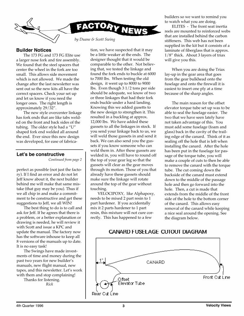
The main reason for the offsetelevator torque tube set up was to beable to seal the fuselage easier. Thetwo that we have seen lately havenot taken advantage of this. Youmust add some fuselage (foam andglass) back in the cavity of the trail-ing edge of the canard. Think of it assealing off the hole that is left wheninstalling the canard. After the holehas been put in the fuselage for pas-sage of the torque tube, you willmake a couple of cuts to then be ableto remove the canard with the torquetube. The cut coming down thebackside of the canard must extenddown to the middle of the passagehole and then go forward into thehole. Then, a cut is made thatextends from the middle of the frontside of the hole to the bottom cornerof the canard. This allows easyremoval of the canard while keepinga nice seal around the opening. Seethe diagram below.
perfect as possible (not just the facto-ry). If I find an error and do not letJeff know about it, the next builderbehind me will make that same mis-take (that guy may be you). Thus ifwe all chip in and make a commit-ment to be constructive and get thesesuggestions to Jeff, we all WIN!
The best thing to do is to call andask for Jeff. If he agrees that there isa problem, or a better explanation ordrawing is needed, he will review itwith Scott and issue a KPC andupdate the manual. The factory nowhas the software inhouse to keep all8 versions of the manuals up to date.It is no easy task!
The Swings have made invest-ments of time and money during thepast two years for new builder’smanuals, new flight manual, newtapes, and this newsletter. Let’s workwith them and stop complaining!
Thanks for listening.Rick
Let’s be constructiveContinued from page 2

Velocity Views 4 Volume 8
All Planes. This hint was men-tioned in an old newsletter but hasbeen overlooked by many so we willrepeat it. When microing the foambefore glassing, let it sit for 1 hour orso before you glass over to allow themicro to begin to tack up a little. Ifyou do this it will help in three ways.First, if you are glassing the wings itwill help hold the bottom two layersof glass while you pull the squigglesout of the Uni. Secondly, when youstart wetting out the cloth, the epoxywill not mix as much with the micro.Third, there is styrene in the epoxywhich tends to melt the wing foam alittle as it is curing. The partiallycured micro acts as a barrier.
Franklin Engine ProjectUpdate
The Franklin engine has beenperforming as we expected. With thefixed pitch prop we will need about a2550 static RPM as a minimum toachieve proper take-off distance. Thiswill result in the need to throttle backa little at altitude to keep the RPMfrom exceeding 2800 RPM. True air-speed has been about what weexpected and has been averagingabout 8 KTS more than a similarLycoming. The engine has been run-ning smooth at any RPM above 1200.Below this RPM expect the engine torun rough. A Velocity builder, DaveLincoln, has been doing someground testing with the Lycomingusing the fuel injection system and adual electronic ignition system fromElectroair. By changing the timing(electronically) he has been able toachieve a smooth idle down to 750RPM. If you elect to stay with onemag, it would be necessary to shutthe mag off during idle and taxi.Manifold pressure brings the timingback to the required advance onceabove 1200 RPM. The fuel injectionnozzsles were moved to the bottomof the cylinders and with this set-up,static RPM is the same as with thecarb. Dave is working with Air FlowPerformance and Atlas Motors andyou can check with Pat at Atlas ifyou need more information regard-ing this change. The fuel injectionwill add about $1,000.00 to the priceof the Franklin (compared to the car-
buretor version). You will also needto purchase a dual pack electric fuelpump set-up from Air Flow as noengine driven fuel pump is availableto run the fuel injection system prop-erly. This will also require some sortof back-up battery pack, with a diodeto prevent discharge, for emergencyfuel pump operation.
We have also been flying withthe IVO pilot adjustable electric prop.Take-off and climb performance arespectacular. As expected, cruise isabout 3 to 4 KTS slower than thefixed pitch prop but certainly goodenough. The major problem is theability of the small electric motor tobring the RPM down once at alti-tude. At 9000 feet density, the lowestI can get the RPM with full throttle(23” MP) is 2700. Fuel flow is about10.5 GPH and speed works out toabout 204 KTS true (234 MPH).Pulling the throttle back to 21 inches,fuel flow went down to 9.0 GPH(leaned to peak EGT), and the RPMsettled on 2550. This will yield a trueairspeed of about 187 KTS (215MPH). In all the tests, I was carryingabout 50 gallons of fuel, and flyingsolo.
Cylinder temperatures are run-ning 360 degrees maximum on thehottest cylinder #1, and about 354degrees on the coldest cylinder #4.Oil temp peaks at about 220 in theclimb and then back down to about210 in cruise.
Other than putting more hourson the IVO prop for confidence, thereisn’t much more for us to do. All theengine install package parts are in, oron order, and should be ready toship by the time you read this. Theinstall package is for the carb versiononly. Prices can be found in our lat-est option catalog, which was recent-ly mailed to you.
GENERAL NEWSSome of you are still using the
(561) 589-1860 phone number whentrying to call us on the weekend. Wewill not answer this number onSaturday or Sunday if were workingbecause we went to the trouble ofputting in an unlisted number justfor you builders. It is (561) 589-0309.If you can’t get through to us during
the normal work day on our regularnumber, try the unlisted one.
The area code for Sebastian haschanged to 561. The old 407 will con-tinue to work into next year, howev-er, you can change now to the newone.
The girls here in the office toldme that some of you have com-plained about us wanting to chargefor the new construction tapes, evento the point of telling us we have nobusiness charging anything for thecost of shipping to get these tapes toyou. Those of you who are building anon-elite model do not NEED newtapes. They are a convenience to youbut not absolutely necessary. Tothose who are building the Elite, wewill give you the Elite portion at nocharge. The wing construction is thesame as what you have now exceptin much greater detail. Hearing thatwe should not charge for these tapesand should prepay the shippingcharges has become an irritation tome. We have spent over $12,000 todate just for the editing of thesetapes. This doesn’t include the hoursand hours of time spent by Mark andNancy in making them available forthe editor, nor does it include theproduction cost.
Here is what we are going to do:If anyone wants all or part of the newtapes, they are yours for the repro-duction cost. This will average $5.00per tape. I’m not sure how manytotal we will end up with, but proba-bly around 12. Those of you whoneed the Elite tapes on the doors andkeel installation, these will be sent toyou at no charge. All you need to dois ask. Don’t ask yet, however,because we don’t have them ready.
We built our first Velocity backin the late 80’s with NO tapes and aconstruction manual about 1/4 thesize of the present one. Most kit air-craft, and no plans airplane that I’maware of, have construction tapes.There are about 80 Velocities flyingand many of these had no tapes or, atbest, the old tapes. Ever wonder howthis could be?
Give us some slack, guys, we’redoing the best we can.

Velocity Views54th Quarter 1996
CRYING WOLFI just got a call from one of the
engine overhaul shops in our area,Don George Aircraft Engines. Don isfed up with Velocity builders whoare having problems with his enginesand blame him for these problems.He takes a very serious positionregarding reported problems andwill send one of his mechanics, or gohimself, to check out any reporteddifficulty. One of his pet peeves is there-installation of the intake tubesafter modification. It is easy to getthem installed with the “O” rings notproperly seated. This causes theengine to run very lean and rough atidle. In flight this can cause seriouscylinder damage. Other problems arein the position of the fuel spider andthe necessity of moving to a locationless prone to heat. Don reports a cus-tomer complaint of hard starting andpoor idle. His investigation indicatedall four fuel lines to the injector noz-zles were only finger tight. Othercomplaints involve oil leakage fromthe front oil seal in the crankshaft.Investigation indicated a kinked oilvent line causing back pressureresulting in oil being forced out thefront seal. Another rough idle reportwas traced to an improperly installedshuttle valve in the stand-by vacuumsystem. He has also investigated a
Velocity complaint that was traced tospark plugs only finger tight. On andon the story goes.
I have known Don since I cameto Florida and have found him notonly a good engine mechanic but alsovery serious about good qualitywork. He has gone out of his way totake care of his customers, only, insome cases, to be blamed for poorquality work. I think what we havedone here is shoot ourselves in thefoot. We have cried wolf so often thatDon no longer wants to do work onVelocity engines. This is a shame.The shame, however, is not his butours.
ARE WE HAVING FUN YETThis past Saturday and Sunday,
Bonnie and I went on a church choirretreat at a place here in Floridacalled River Ranch. River Ranch is aself contained resort complete withmotel type rooms, golf, tennis, horse-back riding, hunting, skeet shooting,swimming, and a variety of otheractivities. Right in the middle is this5000 foot paved airstrip. Guess howBonnie and I got to River Ranch.Because I was the only choir memberto have an airplane, I decided to offerrides free to anyone who wouldshow up during our “open” time. Inorder to provide enough gas to get toand from River Ranch, plus what Iwould need for the rides, I leftSebastian with about 60 gallons offuel on board. The fuel tanks at River
Safety CornerAccident & Incident Reports,Maintenance & Service Difficulties
Accidents & IncidentsThere is nothing more difficult
for me to write about than the infor-mation regarding accidents in theVelocity. Not only does it bring backthe memories but causes me to won-der if giving you this informationdoes anyone any good. I have toconclude that we all benefit by look-ing at the misfortune of our fellow
Velocity pilots and, perhaps, canlearn from these experiences.
Since the last newsletter, we havehad no less than three accidents/inci-dents that resulted in off field land-ings, one of which was fatal to fellowpilot and friend Robert Van Horn.Bob was early in his test flying peri-od when he experienced a flexible oilline failure up near the oil cooler.
This time he was fortunate in findingan airport below him and made asuccessful landing. He called me andtold me his mechanic friend hadinsisted he install the flexible hose,which was apparently a low pressurehose, and that it had ruptured. A fewdays later, according to the FAAreport, an oil line in the engine com-partment blew causing smoke to fillthe interior and Bob was unable tomake it to the airport and struck apower pole killing him. We don’tknow if the same type lines wereused in the engine compartment ornot, fire destroyed all evidence, we
Ranch were not in use during ourstay. This 360 lbs. of fuel, plus my 200lbs., left me with about a 450 lb. limitfor the three seats. Let me now cau-tion you to disbelieve any claimsyour passengers make about howmuch they weigh. On one trip, amother and her two daughters had toweigh at least 250 lb. each. Singing inthe choir will do this to you.Watching them get into and out ofthe Elite was a trip in itself. Our little180 HP Elite struggled into the aireach time without a hint of trouble inspite of the 93 degree heat. Cylinderhead temperature would approach405 degrees on the climb and thenback off to about 390 once level. Oiltemperature would go up to 230degrees in the climb and then back to200 degrees when leveled out. Upand down, up and down we went forseveral hours until their “cup run-neth over”; I was about dead. It’s noteasy to feel comfortable flying with abunch of choir members who aresinging “Nearer My God To Thee”each time the tires left the runway.This is, however, why we build andfly our airplanes. The commentsmade by those who have never seenanything like a Velocity were worthall the sweat and tears involved.Don’t give up friends, there is a rain-bow out there somewhere.
Duane
Factory NewsContinued from page 4
Continued on next page

Velocity Views 6 Volume 8
only know Bob paid the ultimateprice. Bob will be missed by me andhis many friends.
In another accident, the Velocitypilot was flying low over unfamiliarterritory when a banging sound inthe engine compartment was thoughtto be the beginning of an engine fail-ure. Rather than risk flying any fur-ther, this pilot elected to get theplane on the ground ASAP. Thelanding was in a soft cotton field,however, in this case, soft ain’t good.The nose dug in and the planeflipped over on its back trapping thepilot inside. His son was smallenough to slip through the partiallyopen door and get help to get thepilot and another passenger out ofthe airplane with no injury to any-one. The banging noise was found tobe an exhaust pipe that had brokenoff and was flying around in theengine compartment. Although hemight have been able to get to an air-port successfully, his decision to getthe airplane on the ground NOWwas the right one. He has alreadystarted re-building his Velocity.
Another pilot, still in the restric-tion phase of his flight time, had acylinder fail with only about 35hours since overhaul. He made a suc-cessful landing on a small road withno damage to the airplane. No wordyet on what caused the cylinder tofail.
We also received another reportof an exhaust breaking off aft of the#2 cylinder. The broken part wentthrough the cowl opening and took achunk out of his three bladed prop.The airplane proceeded to the desti-nation airport without further inci-dent. The prop can be repaired. Inthis case and the one above, it mighthave been possible to detect the bro-ken exhaust before flight by tappingthe pipe with a coin. A crackedexhaust will have a very distinctsound when compared to one thatisn’t cracked.
That’s it for this issue. Let’s hopeI’ll not have to do this again nextissue.
First FlightsIn the last newsletter I proposed
the question as to our test flying your
airplane for the first time. Theresponse was, more or less, split onthis issue. Some of you gave meexcellent reasons why we shouldprovide this service, others suggest-ed strongly that our value to thefuture success of Velocity would beplaced in jeopardy should anythinghappen during one of these firstflights. Certainly, our experience inknowing the airplane as we do couldprovide valuable information to thebuilder during this first flight. On theother hand, it is rare that everythingcan be accomplished during this firstflight. More often than not, highcylinder temperatures on one cylin-der, high oil temperature, sloppy orstiff controls, and a variety of otherthings could result in the need formore flight testing. These are thingsthat require time to fix and my time(and Scotts) would not allow a twoor three day wait for these things tobe sorted out.
I had many suggestions thatScott or myself provide a thoroughFactory preflight inspection and ataxi test and then let theowner/builder do the actual firstflight. This make a lot of sense butprobably doesn’t go far enough forthe cost involved.
Many suggested that as part ofthe first flight would be a check-outfor the pilot. Legally, this is not pos-sible. The rules provide that essentialcrew only be used for the time neces-sary for the restriction fly-off.Essential crew for a Velocity does notinclude a co-pilot.
What, then, can we do? Theanswer may come from one of ourprofessional builder/professionalpilot individuals who called me andsaid he would be willing to do theinspection/first flight of a Velocity.He is presently flying the Velocity hebuilt, and is checking out the owneras you read this letter. He wouldrequire that the FAA inspection becomplete, engine run to full powerwith a minimum of 2400 RPM static,high speed taxi tests be completed(no lift off) and any problems associ-ated with these tests be addressedand fixed. The price for his serviceswould be agreed upon prior to hisarrival and any work performed by
him to fix a problem could result inadditional costs. If interested, call:Roger Messenger, Messenger AirLtd., Rt. 3 Box 63, Sigourney, IA52591, Phone 515-472-5521
Lycoming MandatoryService Bulletin
Lycoming has issued a servicebulletin on the engine driven fuelpumps used on the injected engines.The identification code is stamped onthe flange of the pump and thoseaffected are #154739506, 154739507,and 154739510. If you have one ofthese pumps installed on yourengine, you will need to get a copy ofthe service bulletin #525, and inspectthe pump per the bulletin. (I have acopy if you need one). Failure of thepump causes total fuel flow blockageand the electric pump will not solvethe problem. This is not good.Compliance is listed as, “before fur-ther flight.”
Deep StallUnder certain conditions, a deep
stall is possible. An aft CG, with anattempt by the pilot to stall the air-craft, could cause a deep stall. This isa condition where the airspeed willgo to “0” as the airplane descends ina “flat”, wings level, attitude.
An airplane within the aft CGlimit could also be “deep stalled” if ahammerhead type maneuver wasattempted. This would be a pilotinduced pull-up to a vertical lineuntil airspeed drops to “0”. Theresulting fall would likely be a “deepstall”.
If intentionally or unintentional-ly in a deep stall, the followingshould be accomplished post haste:1. Extend the landing gear (if anRG)2. Apply full power3. Apply full nose down stick pres-sure4. Hold nose down until airplane“flies out” of the deep stall
Using this procedure, theVelocity factory test aircraft N81VAwas successfully flown out of thedeep stall with a 1200 feet altitudeloss and a 12 second time lapse.

Velocity Views74th Quarter 1996
Continued on next page
Density Altitude and ItsEffect on Take-Off Distance
We have had a couple of closecalls and one overrun when a take-off was made in high density condi-tions. How can we easily determinethe take-off distance needed whenwe are faced with the possibility of ahigh density altitude take-off?
The first step is to determine justwhat the density altitude is. The oldE-6B computers would give us agood idea of density altitude giventhe pressure altitude and tempera-ture. What if we don’t have an E-6Bhandy? File this formula away in aconvenient place for reference ifneeded:
Step 1: Take field elevation X.0054
Step 2: 59 - (Step 1)Step 3: (Actual temp in °F) -
Safety CornerContinued from page 6
Short Circuitby Martin Hadley
Compass CalibrationOne item that is often taken for
granted in an airplane is the magnet-ic ‘wet’, or ‘whiskey’, compass. Alltoo often its accuracy goesunchecked or calibrated.
Checking and calibration of thisinstrument is not hard to do. Atmost public airports in the country, acompass ‘rose’ has been painted onramp space somewhere either by thecontrolling agency or by the interna-tional organization of flying womenknown as the Ninety Nines. (Mostby the latter!) Locate a field close to
you that has one and take a friendwith you to help.
Besides the friend that is going tohelp you line up properly on thecompass ‘rose’, you will need a non-magnetic screwdriver, usually madefrom brass, a pad of paper, andsomething to write with.
First, check your compass north,south, east, and west readings by lin-ing up your aircraft properly on thecompass ‘rose’ and record your com-pass readings. Normally, for exam-ple, if your compass readings are 3degrees right of north (or 003) youwill be 3 degrees right of south (or183). The same applies for east andwest. In any case, always adjustyour east/west error first! (Thisadjustment will effect yournorth/south reading dramatically ifthere is a big error to correct.) If thereis no error in east/west, then adjustthe north/south.
After you have rechecked allfour headings one more time, andmade whatever fine adjustments thatmight have been needed, you need tocheck and record your compass read-ings on 30 degree increments of thecompass (i.e. 000, 030, 060, 090, 120,
(Step 2)Step 4: (Step 3) X 66Step 5: (Step 4) + (Field
Elevation) = Density AltitudeAs a rule of thumb, add 400 feet
of additional take-off roll for each1000 feet of density altitude.Example:Airport Elevation = 5000 ft.Outside air temp. = 80°F (temp. onthe runway)
Step 1: 5000 X .0054 = 27Step 2: 59 - 27 = 32Step 3: 80°F - 32 = 48Step 4: 48 X 66 = 3168Step 5: 3168 + 5000 = 8168 Feet
Density AltitudeAt GROSS the standard Velocity
will take about 1400 feet to rotate atstandard temperature of 59°F. So-o-oo, if our density altitude is 8168 feet,our take-off roll will be INCREASEDby 8168 X .400 = 3267 feet. If we addthe 3267 feet to the 1400, we get 4667feet. You may need to add even moreif your airplane has a high time
engine (less power), a cruise pro-peller, or – for whatever reason –would take more than 1400 feet oftake-off roll at gross at S.L. on a 59°Fday. On the other hand, if you havetested your airplane at various highdensity altitude and find perfor-mance better than the exampleabove, your knowledge wouldsupersede anything I say here. Thiswould be especially true if you wereusing a constant speed prop in placeof the fixed pitch.
What I am trying to say is to nottreat density altitude lightly. This canbe a serious problem. If you findyourself in a situation where densityaltitude may be a problem try a take-off with a light load. If this works outOK, add some weight and try itagain. Work your way up to themaximum weight you plan to carryinstead of all at once. Remember toleave yourself some margin for errorand don’t take unnecessary risks.
Duane
etc.) The headings that you recordare the numbers that go on yourcompass correction card. (Asrequired by FAR 23.1547)
Now for those unexpected prob-lems! Once in a while you will getreadings such as East (087) and West(273). Instead of a consistent error tothe right or left of heading, it tendsto favor a hemisphere. This type ofreading is usually cause by some-thing in the cockpit effecting themagnetic compass. First of all, getthat magnetic Phillips head screw-driver out of the glove box, or sidepocket, and replace it with a non-magnetic type! Do you have a pocketscrewdriver with one of those littlemagnets on the end in you shirtpocket? Throw it in the back of theplane! (Believe it or not, even thesmallest magnets within 2 - 3 feet ofa compass can effect it.)
Now check the instrumentpanel. What type of screws are in theinstruments, holding the glare shielddown, and what other items of steelare within close proximity of thecompass? Those of you that haveflown the older Mooneys will

Velocity Views 8 Volume 8
remember having their airframesdegaussed (de-magnetized) becauseof the tubes coming down from theroof to the center of the windshield.Remove any questionable items oneat a time. If no change is noticed,reinstall it.
If you do not find anything ofsteel that is effecting the compass,start removing pieces of electronic orelectrical equipment. Some hightech digital radios use magneticimpulse coupling to select radio fre-quencies, adjust OBS settings onNavigation indicators, etc. Someautomotive type indicators withpointers use relatively large mag-nets to move the needles. Once youhave found the culprit, replace it orrelocate it. Then go back to the top ofthe second paragraph.
Believe it or not, you are allowedup to 10 degrees in error, providedthe compass correction card indi-cates the erred reading for the truemagnetic heading you wish to fly!Obviously, the more accurate thereading on the compass, the lesscockpit confusion there is to over-come.
How to Safety WireThose of us that have trained
and/or have been educated in thefield of aviation construction andmaintenance take for granted a goodmany things that seem so basic andsimple, that we forget a simple fact.Most builders of experimental air-craft have their talents and expertisein areas other than aircraft construc-tion and maintenance, and the lackof basic techniques used in construc-tion and maintenance needed in avi-ation. It is the goal of this feature todiscuss the procedures and objec-tives of many of these ‘simplethings’ that most builders havenever done.
This particular article has beeninspired by the recent inspection of a‘safety wire’ job done on a prop byone such builder.
The objective of safety wiringsomething is simple...prevent thebolt (or bolts) from loosening and
backing out. The proper techniqueused to accomplish this is not so sim-ple. It is not difficult though, either.For this discussion, refer to drawingabove. (Those of you who knowabout drafting and drawing willquickly realize that I don’t!)
Again the objective is simple,prevent the bolt(s) from loosening, orturning counter clockwise. To prop-erly safety wire these two bolts youneed to do the following: Cut a suffi-cient length of safety wire that willallow at least 1 1/2” of wire on thefinal twist. Now insert the wire inthe top bolt head and bring the endcoming out of the 8 o’clock positionOVER THE TOP of the bolt (clock-wise rotation) and BEHIND the endcoming out of the 2 o’clock position.Hold the two wires together, and bymaking a backward “S” between thetwo bolts, determine the length need-ed to reach the 10 o’clock position ofthe bottom bolt. Now twist these twowires in a clockwise rotation so thatthere is a dual, intertwined, spiralstaircase effect (double helix). Do notwrap one wire around the other likean outside staircase on a lighthouse.The end coming out of the 8 o’clockposition needs to be behind the 2o’clock position to help insure that itdoes not ‘slip’ over the bolt head.The short distance of wire that weare talking about is effectively the“pull wire”, keeping the top boltfrom loosening.
The twists of the safety wireshould end right at the 10 o’clockposition of the lower bolt whenpulled snugly from the top bolt. The
Short CircuitContinued from page 7
wire that should be inserted into thehole is the one that comes closest tocomfortably “rolling” into the hole.The other end will automatically fallbehind the wire going through thebolt safety hole and it should contin-ue around, in a counter clockwisemanner, behind the wire exiting the 4o’clock position. Tightly pull the wirethat wraps around the bolt head andtwist it snugly at the base of the wireexiting the 4 o’clock position in aclockwise rotation. (Remember,behind the wire exiting the hole andtwist it in a double helix!) Twist thesetwo wires approximately 1 1/2”.Now cut the twist 1 inch from thebolt head and double the twistedwire back so the end just touches thebolt.
If any safety wiring job has beendone properly, you should be able toobserve the following;1) If one bolt tries to loosen, it willtry to tighten the other bolt.2) No wire, except the last 1”, has asingle point bend greater than 90degrees.3) The wire that ‘wraps’ the bolt headwill not pull over the side of the bolthead, allowing it to be on top of thebolt head.4) There is moderate tension on thetwisted wire between the two boltheads. Any movement of either boltshould result in movement of theother bolt.5) No wire should protrude higherthan the head of the bolt.6) A full or partial backward “S”should be visualized with the wireswrapped around the bolt headsforming the ‘hooks’ of the backward“S”.
A rule of thumb for the diameterof the safety wire needed, it shouldbe at least 1/3 the diameter of thehole it is going into.
As it is with everything, to safetywire properly takes some practice.Seldom does anything such as thiscome naturally. It is not difficult todo correctly though if you knowwhat you are trying to accomplish.
Safe and Speedy Construction!

Velocity Views94th Quarter 1996
Kit PlansC h a n g e s“ K P C s ”
Note: Check the date at the bottom ofyour page. If it matches the “Date ofChange” shown in the KPC, your man-ual has already been corrected.
KPC 029Affects: All Standard Wing VelocitysManual Section: 4.4.4Date of Change: 9 July, 1996
Change the last part of the first para-graph to read: “Measure and mark77” outboard of this center point andsquare off the canard ends.”
KPC 030Affects: All VelocitysManual Section: 4.6.1Date of Change: 15 Sept, 1996
Change the gap width in Figure 4-37from .020 to .200”. (Note: the gapcan be up to .250”)
KPC 031Affects: All Velocitys with cantedinstrument panelManual Section: Figure 5-1Date of Change: 1 Sept, 1996
Note that the copilot side of thepanel is 1-3/4” aft of the pilot sidebecause of the canted portion.
KPC 032Affects: All RG’sManual Section: 9.5.3, Main GearDate of Change: 1 July, 1996
The Figure shows the upper maingear door attachment tab beingscrewed into the gear leg, but thetext says to glass the tab on. Deletethe section of text and follow theFigure.
KPC 033Affects: All RG’sManual Section: 9.6.3, Hydraulic
Plumbing SchematicDate of Change: 1 July, 1996
Change the part numbers of theelbow, sleeve, and nut coming out ofthe dump valve to:AN 822-4-4DAN 818-4DAN 819-4D
KPC 034Affects: All Elites with speed brakeManual Section: FG-10.2.1, RG-10.2.4Date of Change: 9 July, 1996
Change the size of the pilot side alu-minum bar for the seat hardpointfrom 6.5” to 5.5” long.
KPC 035Affects: All RG’sManual Section: 12.3.1 page 12-11and page 12-13Date of Change: 1 July, 1996
Change the angle of the aileron bell-crank to 10 degrees from vertical.
Note: a postcard was mailed to allbuilders for KPC 035
KPC 036Affects: All 173’sManual Section: FG-14.3, RG-14.4(Outboard Strake Reinforcement)Date of Change: 1 July, 1996
Increase the size of the Triax strips to4” x 29”.
KPC 037Affects: All RG’sManual Section: 14.3.1 Figure 14-15Date of Change: 9 July, 1996
The inboard strake bulkhead thatparallels the fuselage is erroneouslyshown as two bulkheads. Change thename of “J” to “E”. It is one bulk-head.
KPC 038Affects: All RG’sManual Section: 14.5.1 Figure 14-29Date of Change: 15 Sept, 1996
Change the front bottom sump tankfitting to 1/4” pipe, 3/8” hose
KPC 039Affects: All VelocitysManual Section: 17.1.2Date of Change: 15 Sept, 1996
Change paragraph four to read:“Position the engine so that the cen-ter of the prop extension is actually3/8”-1/2” above the center of thecowl outlet. This is because the rub-ber mounts will sag after a few hoursof operation. Also rotate the pilot’sside of the engine down a 1/4” or soto help with cowl clearance. If youdon’t do this, the top of the cylinderwill contact the top cowl.”
KPC 040Affects: All VelocitysManual Section: 20.2.10Pages 20-17,18Date of Change: Delete references totilting the engine up 1 degree. Noshims are needed between themount and the firewall.
KPC 041Affects: All RG’sManual Section: 17.5 Figure 17-12,Heater ValveDate of Change: 1 July, 1996
This figure is supposed to be a full-size template of the heater valve, butit magically got shrunk. It needs tobe enlarged to 124%, or add 3/8” tothe top, left, and right sides and 1/2”to the bottom. (The top refers to thetop of the page)
KPC 042Affects: All VelocitysManual Section: Elites: 10.3.4, Non-Elites 10.2.6Date of Change: 1 July, 1996
The rear view in the control stickassembly figure (Elites: 10-14, Non-Elites: 10-12) shows the bolt attach-ing the control stick to the ailerontorque tube going the wrong direc-tion. The head of the bolt should beon the pilot side. The side viewshows it correctly. Also, there is nosleeve over the control stick itself.The molded handgrip supplied inthe kit merely slides over the steelstick.
Velocity Views 10 Volume 8
are two Holiday Inns in StAugustine...make sure you go to theone at the Beach (see map).
• Saturday Night Dinner:- Dinner at 7:00 pm at Holiday InnBeach (St Augustine Beach)Florida style buffet includes: salad,grilled NY strip steak, broiledshrimp, vegetables, baked potato,rolls. Attorney Mark Ewart address-ing legal concerns for experimentalaircraft liability, followed by abuilder’s Q&A session with theSwings (factory owners).
Cost:- Lodging cost @ $55 per night perroom- Dinner cost $21 pp / $10.50 kids 14& under (includes tax & gratuity)
• Reservations:- Make your own reservations ASAPbut no later than October 20th! Feelfree to alter your arrival and depart-ing dates according to your ownschedule when you book your reser-vations. Contact the Holiday Inn andspecify that you are with the VelocityGroup! Call 904-471-2555 to bookyour room. Velocity Inc. has 20rooms blocked off. To be sure thatyou get a room, call right now andbook!
• “...but my Velocity is notfinished yet”...
Don’t feel like you can only go ifyou are flying a Velocity. Rent a 172or bum a ride, or God forbid, evendrive! Judy and I drove to the lastfly-in at Winter Haven.
VelocityFlorida
Fly-in
VelocityFlorida
Fly-inDuane Swing has planned
another fun outing for Velocitites. Itinvolves all the things I love to do;flying, meeting with old friends,making new friends, eating, and theexcitement of being at an airportwith a bunch of Velocitys! Here arethe details:
• Who should go: Anyone flying, building, or dream-ing of a Velocity (and, of course,your spouse or guest).
• When:Saturday Nov 2nd andSunday, Nov 3rd• Where:St. Augustine FloridaIdentifier: KSGJ
• Saturday Nov 2, 1996• Historic St. Augustine• Airport Cookout• Dinner & Speaker• Builder Q&A session
• Arrival Time at SGJ airport:11:00 am Saturday Nov 2nd
• Saturday’s Activity:- Noon cookout in front of the newairport terminal building courtesy ofVelocity Inc.- Afternoon open to see the oldestcity in America or hang out on thebeach. We will have a large van ortwo (courtesy of Velocity Inc.) at theairport to shuttle Velocitites withoutcars to the city or the Holiday Inn,etc. Other Velocitites with cars canalso help out with transportation.
• Overnight Lodging:- Holiday Inn at St Augustine Beach.The Holiday Inn is right on a beauti-ful 7 mile long sandy beach! There
About “St. Augustine”The old city is a great place to walk, tour and shop. The entire down-town section has been beautifully restored, with quaint pedestrian-only streets and a central Plaza, flanked by a beautiful Cathedral.Visit the Castillo de San Marcos (original fort built by the Spanish), orany number of attractions. In the restored Spanish Quarter, coloniallife is recreated in a living history museum village. The city has manyhistoric buildings to tour, including many “Flagler Era” churches, pri-vate and public buildings (including Flagler College, built in 1888 asthe Hotel Ponce de Leon). Museums are numerous, with the magnifi-cent Lightner Museum of Victorian era collectibles, the GovernmentHouse and the “Oldest House” and more. Antique collectors find lotsof treasures, and there are many art galleries and unique shops. Thereare lots of good restaurants, even if you just want a French pastry orEnglish tea. Scenic sight-seeing trains, horse-drawn carriages andbayfront cruises are popular ways to see St. Augustine. The Fountainof Youth, Ripley’s Believe It or Not, Potter’s Wax Museum and theAlligator Farm are popular attractions too. Outside the city at I-95 is ahuge factory outlet mall of over 100 stores. Much too much to fill justone weekend...and we haven’t even mentioned the beach!

Velocity Views114th Quarter 1996

Velocity Views 12 Volume 8
B u i l d e r sF o r u m
Builders Forum is full of tips, information and letters (“material”) supplied toVelocity Views Newsletter from individuals that are Velocity builders (or want to bebuilders). It is provided as “USE AT YOUR OWN RISK” material. NeitherVelocity Inc. (The Velocity Factory) nor Velocity Views Newsletter (Lavoie Graphics& Rick Lavoie) have endorsed this material, and disclaim any liability for the use ofthis material. Individuals who use this material for the operation, maintenance, orconstruction of their homebuilt aircraft do so at their own discretion and at theirown risk. Any variance from the builders manual is high risk.
From Jim Agnew, Tampa, FLWindow Installation Tip
The manual tells us after micro-glassing the windows in to cut a linearound the tape on the inside of thewindow following (as close as possi-ble) the window cutout.
This is much easier to do if youhave a single layer of duct tape onthe inside of the window. Take asmall flexible strip of metal (I used a6” stainless steel rule 1/2” wide)and shine a bright light in from theoutside thru the frame. You canclearly see where the frame endsand the outside duct tape starts. Justline your rule up with the shadowand take your time following theline. Its a lot better than guessing!
•••••••
From Cory Howe, Little Rock, ARApplying Micro Tip and more...
Howdy, my name is Cory Howefrom Little Rock, AR and I havebeen building a 173 RG Elite forabout eighteen months now. It hasbeen a very enjoyable and excitingproject. I am coming down to thewire on the completion of this pro-ject or should I say the wiring. Allof the fiberglassing and fill work isdone. Everything has been primedand many parts ready for paint. Theengine was installed about a monthago and many of the electrical piecesare now being mounted in place.
I am always anxious about get-ting the Velocity Views because ofthe things I learn from otherbuilders. In that sense I am writingabout a few things that I wish I hadbeen more knowledgeable about afew months ago. 1.) One of the problems aboutapplying micro to a surface, such asthe wings, is the fact that the microwants to curl up around the trowelinstead of sticking to the surfacewhen it is being applied. A good
friend and fellow velocity builderMike Pollock from Dallas gave me atip he got from Dick Rutan. The tipis to wet the wing surface with pureAlphapoxy with a dampened ragbefore applying the micro. You onlyneed enough Alphapoxy to dampenthe surface and any more would justbe wasted weight in epoxy. With thesurface wet the micro adheresextremely well and eliminates theproblem of micro curling up and notsticking to the fiberglass surface.2.) In retrospect, I would have beenmore cautious about the amount ofmicro I applied in the area of theailerons. I had to add additionalweight onto the aileron for balancingpurposes. 3.) When installing the pulleys forthe main gear retract system try toinstall them as low as possible. Inthe Elite version the aileron bell-crank is installed just above the areawhere the main hydraulic cylinderarm and cables are moving. Thelower the pulleys are the lower thecables are which means you havemore clearance for the movement ofthe aileron bell-crank. That is a goodthing.4.) When installing the top strake tothe fuselage there was one thing Ineglected to do which had to be fixedafter the fact. In the area of the top
strake next to the fuselage where thefuel tank resides below (or in otherwords about the aft 1/3 of the topstrake next to the fuselage) I wouldrecommend that the foam beremoved between the inner andouter skin and filled with wet micro-glass or flox. This should eliminateone possible leak point.5.) When installing the wheel welltry to keep as much room as possiblebetween the aft fuel bulkhead andthe wheel well. Having more dis-tance will allow for an easier timesealing the inside of the tanks withepoxy. I did not have much roomand it was difficult to get epoxy inthat area. 6.) If you are installing a Franklinengine in an Elite you may have
found that the engine mount boltsinterfere with the sump tank. I hadto cut my sump tank open with aband saw and re-glass it to allow

Velocity Views134th Quarter 1996
space for the engine mount bolts.(See picture)7.) In starting the interior of theplane I came across an aircraft seatupholstery shop. They built four ofthe most beautiful seats I have everseen. They are made from a specialvinyl looks and feels just like leatherwithout the cost. This covering haspassed the FAA FAR #25.853 andCalifornia Flammability Regulation117-75 flammability tests. It is alsostain, abrasion, and mildew resistant.
Not only do they look and feel goodbut they are extremely comfortableand come in an assortment of 20 col-ors. If you would like more informa-tion please call Horizon Enterprisesat 501-835-5066.
I am looking forward to readingmore comments and ideas in theupcoming Velocity Views.
•••••••
If your label reads“Paid thru Vol 8”, then
this is your lastnewsletter unless you
renew byDecember 20th.
See Page 19.
From Dave Black, Woodbridge, VAMods Antennas & Tools
Concentric Torque Tube Bearing:
In Volume 4, I mentioned all theadvantages of my concentric torque-tube mod but failed to give the bear-ing size needed. I apologize. TheFafnir KP6A (available from Spruce)will do nicely. Fasten in place withAN6-15 bolt, MS 20142-6 stop nut,and four thick washers.
Strake Top Reinforcement:
Just prior to painting we foundmany little dents in our strake sur-face. We determined these had beenmade by elbows and other hardobjects during the process of con-struction. To end this damage wedecided to toughen the top strakeskin. We laid on a single ply of car-bon BID, since it is about six times asrigid as the equivalent weight glass.But that may have been overkill. Oneply of fine glass BID should do thetrick. Be sure to sand through theprimer down to the glass. The BIDshould overlap the join-line at theleading edge.
Aileron Trim Mod:In volume 5, Bill Wade showed
an improved aileron trim actuator.Bills system replaced the slippage-prone motor and string system withone built around the MAC-8A servo.I was intrigued by Bills design, but inbuilding mine chose to eliminate the
string and pulley entirely. My 8Aservo is mounted directly to theaileron control bracket, where itslides an aluminum bar. On the left,the bar is held in alignment by a cus-tom-made 3BID fiberglass strap. Bothends of the bar have an L-bracket towhich is attached an eye bolt withlocknut. The original springs connectthe eye bolts to the bell crank. Thisnew system retains the non-slipadvantage of Bills system, but alsopermits accurate tensioning of thesprings. It should be simple to centerthe servos range and adjust springforce. And it operates very smoothly.
Antennas:In previous issues, we noted the
antennas originally installed in ourVelocity wings and winglets wereplagued by a laundry list of designand construction flaws. After thor-ough testing and gnashing of teeth,we determined the old antennaswould have to be completelyremoved.
Using our MFJ AntennaAnalyzer, we easily located thedefective antennas along the leadingedge of the outer winglet skins. Aftersanding off the primer and fill weused our rotary cutter to slicethrough the skin. We peeled the glass

Velocity Views 14 Volume 8
from the foam and pulled out allpieces of the original antenna, alongwith its cable. We were able to pullthe old cable completely out of thewinglet through the position lightmounting hole. To install the newcable, we drilled a 1/4 hole throughthe foam just inside the winglet lead-ing edge. Where the old antennasand cables had been removed, wefilled the gashes with bubbles, sand-ed, and glassed over with 3 fine BID.
Because carbon fiber detunesantennas just as aluminum does, wefeared we would be forced to removethe carbon reinforcement from theentire rudder line of our winglets.However testing showed that if wecarefully positioned our Sportcraftantennas directly on top of the car-bon fiber, we could nearly eliminatethe adverse effects. We fixed theantennas in place right on top of theexisting glass skin using a moistresin/fiber mix. We held everythingin position with rivets and maskingtape until the resin cured (photo).Then with 1 fine BID, we glassedover the Sportcraft antennas. Whencured, we filled and sanded untilsmooth.
The above SWR chart shows theresults of our finished installation(For comparison, see the SWR plotsof our original antennas in Volume4). While not perfect, our SWRremains below 2:1 across all but thevery bottom of the Comm band. Tohave reduced the SWR further wouldhave required rebuilding thewinglets minus the carbon.
The number of calls we havereceived concerning dysfunctionalantennas shows our antenna experi-
ence is all too common. Our advice:Spend the $50 or $120 for Sportcraftor AAE antennas, or build LarryCoens antenna (volume 5). But nomatter what antennas you use, SWRtest your installation before youglass everything permanently inplace. Its easy to make adjustmentsat this stage, and it may save youlots of headaches later.
Advice for New Builders:During my two-year building
process, I have learned a few thingswhich I hope may be of value to newVelocity builders.Get Help:
First, home builders as a groupare the friendliest and most helpfulbunch of folks Ive met. Everybuilder and potential builder I havespoken with has freely offered valu-able suggestions and tips. Thus I rec-ommend you not build yourVelocity in isolation. Talk to otherbuilders. Join the EAA (800-843-3612) and take advantage of theexpertise offered by their TechnicalCounselors. Subscribe to the CentralStates Newsletter (9283 LindberghBlvd, Olmsted Falls, OH 44138-2407)for information on canard aircraft. Ifyou’re on the Internet, keep an eyeon rec.aviation.homebuilt. If you arenot sure of something, call the facto-ry — they are always helpful. And ofcourse, renew your subscription toVelocity Views.
When to Assemble Wings:Beginning your kit construction
with the wings will give you animmediate sense of accomplishment,but I believe there are good reasonsto delay this particular phase of con-struction: 1) The completed wings are awk-ward and subject to damage. Theymust be kept protected from the ele-ments. If you are building in a 25 x35 area, this is no problem. But formost builders, space is at a premi-um. On the other hand, theunassembled blue foam can bestored in any cubby-hole, wherespace and damage are not an issue.2) New builders may not have expe-rience with fiberglass construction.They would build lighter, stronger
wings if they sharpen their fiberglassskills first by working on the smaller,easier to manage lay-ups found with-in the fuselage.
Thus I suggest delaying wingand canard construction as long aspossible. The first time you actuallyneed your wings is when you areready to close the strakes. And forthat operation, the winglets need notbe installed on the wings. If youleave the winglets off until you actu-ally need them, the wings will be lotseasier to handle and store, andthere’s that much less to carryaround and get damaged while youare working on the strakes.
Just in Time:Don't build ANYTHING until
you actually need it. That statementgeneralizes the advice above.Looking back, we could have savedsubstantial time and effort if we hadfollowed that philosophy throughoutthe project. We have discovered timeand again that a subassembly or partwe built ahead of time required mod-ifications by the time we wanted toinstall it. There are several reasonsfor this: Once you are ready to installa particular subassembly, you have avery good idea how it fits into theproject. You may have come up witha better way to build it. Or make it fitbetter. Maybe the factory has issuedan improvement or KPC. Whateverthe case, there appears little advan-tage in getting too far ahead of your-self. Or so it seems to me.
Helpful Stuff:You can build your Velocity with
common supplies and shop tools.However a few additions can greatlysimplify your construction process.Self-Tapping Screws:

Velocity Views154th Quarter 1996
We use self-tapping screws tohold large parts together while theycure, then remove the screws beforeglassing. For example, we used themto hold the side channels and centerconsole to the fuselage while theresin/fiber mix underneath theflanges cured. After removing thescrews we accomplished the pre-scribed lay-ups.Super Glue:
Where you need to hold smallparts precisely in alignment forglassing, super glue (cynoacrylate,also known as Hot Stuff or Zap/CA)works wonders. It is much faster andis more convenient than Bondo. Usedwith Zip-Kicker (accelerator forcynoacrylates, available in hobbystores) the super glue sets instantlyand is surprisingly strong. Notstrong enough, however, to use foranything more than holding partswhile the resin cures.
SprayLat:There are lots of ways to protect
your Plexiglas during constructionand painting. But this has to be theeasiest. We inlined the windows withelectrical tape, then brushed severalcoats of SprayLat onto the Plexiglas.When it dries it provides a protectivefilm. Then when you want to removeit, SprayLat peels off easily.Available through Spruce.
West System:When you get to the filling and
sanding portion of your project youmay want to consider West System105 resin and 205 hardener in placeof the Alphapoxy or Velocipoxy sup-plied with the kit. West has theadvantage of a relatively fast curetime (about two hours), and hasgood sanding properties. Its avail-able from Spruce but we got oursthrough the local boating store(saved a little money and it was instock).
Car Wax:A useful addition to release tape.
Cured fiberglass will separate easilyfrom any surface covered with wax.To guarantee easy removal of thecured part, before glassing just smeara thin coating of car wax on top ofthe mold or whatever release tapeyou are using.
Belt Sander:This is absolutely the perfect tool
for trimming and shaping fiberglassparts. But we've found it quite handyfor shaping or smoothing aluminumparts as well. We used it on theabove aileron trim mod.
Air Tools:If you have not discovered pneu-
matic tools, you should! Air tools areinexpensive and lightweight com-pared to their electric counterparts,allowing you to work in tight placesthat would otherwise be difficult orimpossible. Because of air-cooling,they do not overheat. But they arenoisy, so be sure to wear hearingprotection. Most tools cost in the $20-50 range at Harbor Freight (800-423-2567). We have found the followingto be especially useful:
Blower - Great for quick cleanups.
Die grinder - We call it our dentaltool, because that’s just what itsounds like. The tree-shaped rotaryburr (shown) is indispensable forprecisely shaping and trimming glassparts and fillets.
Cutter - Cuts fiberglass without de-laminating. Great where you don'twant to cut completely through apart.
Angle die grinder - Gets into placesthe straight one will not reach. Fittedwith a 3 disc (shown here), its alsouseful for sanding and grinding.
Drill - Small and powerful. Beatselectric!
Angle drill - Gets into tight places.
Body saw - A handheld jigsaw fitsinto all kinds of tight places and cutsnearly anything. Absolutely indis-
Dave’s Air Tools (in left to right order )

Velocity Views 16 Volume 8
pensable.
Orbital sander - Useful for removingrough edges from cured glass or forpreparing a cured surface for anadditional lay-up. Not for finishsanding!
Air compressor - Most air toolsrequire 4-10 cubic feet per minute ofair at 90 pounds pressure. A 1-horse-power compressor simply can notkeep up with the tools. Our tried-and-true 1-hp compressor boughtthe farm only one month into ourVelocity project. We replaced it witha 5-hp compressor we discovered atSams Club for $300. It has served ussplendidly through our entire build-ing process.
You may contact me at (703)590-2221 or [email protected] .
••••••••
From Alan Shaw, Dynamic WingCompany, Melbourne Florida
[email protected](407) 253-1975 fax 3868
Antennas, Canard, Elevator, WingPropellors, Information & Tips
Antennas:At the Wing Co. we have always
tested our antennas. In the past wejust did conductivity test but forover one year now we have alsobeen testing the percentage of signalreflected back to our test transmitter.Having made over 200 different test
readings, we have found the basicdipole antennas very adequate formost VFR aircraft uses. Howevertheir efficiency is mostly in the centerof the band with wide variations par-ticularly at the extreme high and lowfrequencies. This is surprising con-sidering that the aircraft AM band isrelatively narrow.
The one set of “SportcraftAntennas” that we installed provedto be the most efficient particularly atthe high and low frequencies. Thistype of efficiency means that com-municating with “Center” at muchgreater range is possible. Also trans-mission from the ground to an air-port departure control 20 miles awayis possible. I have to agree withDavid Black that the small expense ofthese better antennas are well worthit. For this reason we are changingour standard com antenna installa-tion to Bob Srcher’s SportcraftAntennas.
Canard aerodynamicsThe “EASY” type configuration
is complex to predict what differentvariations will produce. The Velocityis a versital and forgiving performeryet we still don’t fully understandhow we got so lucky. At Oshkosh ‘79I had the fortunate opportunity ofhaving a 30 minute one on one con-versation with Burt Rutan while sit-ting under the wing of his Defiant.Burt made it clear that the basic ruleof thumb was to keep the wing load-ing on the canard double that of themain wing but eluded that therewere other factors at play.
For the last 17 years I have builtand tested scores of models; conven-tional, canard, three wing, etc. and ofcourse real Velocities. What I havelearned is that you can stretch thatfirst rule of thumb by changing theother factors and get better perfor-mance but still retain stable charac-teristics. The rest of the factors andthere average ratios of differentiationfore to aft look like this:1 loading per unit area 2 to 1 (Burt’s)2 angle of attack 2.5 degrees to03 camber radius 2 to 1 4 aspect ratio 2 to 15 wing area 1 to 56 coefficient of lift 2 to 1
7 gremlin odds 10 to1(that anychange will make things worst)
The general rule is if you lessenthe difference between the front andrear wing by one factor you have toincrease it by another to retain thesame stability. Infinite different com-binations of different ratios betweenthese factors are mathematically pos-sible. What the designer looks for arecombinations that give a compromisebetween stability and performancethat is acceptable within certainflight parameters. Conventional air-craft violate factors #1 & #2 whenthey try to fly too slow. That’s whythey stall and spin. The designershave limited the flight envelope tomaintain stability. For anything butan aerobatic aircraft I find this com-promise unacceptable and morbidlyappalling.
Applied to “EASY” types thisdifferential wing principle is quitehelpful. For example the commonsolution for a canard that feels unsta-ble at low speeds and may deep stallis to cut some off the tips. Sure thisincreases the loading differential butit decreases the aspect ratio differen-tial. At the given low airspeed it mayor may not be more stable but it can’tfly that slow anymore so who willever know? The problem may be inthe airfoil and twist of the main wingor the toe in and inward tilt of thewinglets. Roll and yaw instabilitiesalways progress into pitch instabili-ties(and pitching can manifest rolland yaw). If the main wing is OKthen perhaps the solution to thisproblem is to make a new canardwith less cord, more camber and ahigh lift device type elevator. Thisway you can take off and land shortand slow. It also may make it possi-ble to load big people or little peoplein the nose and still fly stable at allspeeds.
The Velocity has a much widerloading and speed range than previ-ous canards because of the size of theelevators and the strakes. At 40%(the norm is 25%) of the canard’s totalcord the elevators became a trim flapform of variable geometry. At aprox.50% of the total main wing area thestrakes lower the aspect ratio andraise the coefficient of lift at landing
Time to Renew yourSubscription toVelocity Views
See invoice on page 21
If you do not renewby December 20, 1996,your name will bedeleted from the mail-ing list. No invoice ornotice will be mailed!

Velocity Views174th Quarter 1996
With full aft stick check for fullaileron travel. Yes, the joy stick holein the console needs to be square.
Wing Sail riggingWinglets produce thrust just like
sails. When they are not sheeted inenough the plane is yaw unstable atlow speed and may luff at 135 knotsand 2300 rpm (the harmonic frequen-cy of the main wing structure).When sheeted in too much, drag andside loads are too high at cruise. Thecorrect angle of attack, toe in, onyour winglets makes your planefaster at cruise and easy to handle onlanding.
Making winglets taller effective-ly increases the wing span and aspectratio of the main wing. This decreas-es top speed and roll rate but increas-es structural loads and climb rate.
PropellersThis is the most important and
least understood wing on the airplane. We have some fixed pitchprops that cruise faster than even themost expensive constant speed mod-els. High tip velocities makes the last6” do all the work. Props that don’tperform are always “club” shapedand ridged at the tip. Centrifugalforce is what keeps props frombreaking from thrust loads so the tipscan be made thin and flexible. What works best on a Velocity is awood and/or composite prop that issomewhat like the WW1 “Simitar”ones. These new high speed versionshave only a little sweep back at thetip. The structural fibers sweeptowards the leading edge letting thetip twist. This way they flatten onclimb and resume full pitch when offloaded at cruise. Ideally we want2500 rpm on take off and no morethan 2700 rpm level flight at altitudeand full throttle. Most good fixedpitch props should deliver onlyabout 300 rpm difference betweensea level take off and full throttle at10,000’.
Performance differences betweenprops varies incredibly. Even twoprops from the same manufacturerwith the same specs cut very precise-ly will perform slightly different. Bepatient working with your prop sup-
one time. They also have to bestraight forward, the right depth and1/8” behind the trailing edge of thecanard (12” behind the L.E.). If thehinge point is directly under thecanard trailing edge it is geometrical-ly impossible to get more than 15degrees of up travel. I don’t knowwhy I mounted over 40 sets of thesebefore I molded a jig that does it con-sistently correct with ease.
Assuming the elevator is hingedcorrectly their are still five moreways to mess it up that result in fastlandings. Test of the standardwinged Velocity worked best by lim-iting the elevators high lift potentialwith at least 3/8” x 42” leading edgecuffs. At 26 degrees down the gapshould be .200” up to the canardtrailing edge. We are just beginningto find out that the 173 wingedVelocity needs all the elevator highlift device it can get. Currently weare making 173 elevator cuffs only1/4” deep and the gap 1/4”. The 173appears to have a lot more low endpotential but we don’t want to pushit until after we do some Alfa curveflight test on a several different ones.
All of the test canards that DanMaher made had bare glass underthe trailing edge on the back side.This rough surface stirs up the air sothat more will pass through the slotand over the top of the elevator. Ifyou have already made this partpretty just sprinkle a little sugar inthe paint back there..... home mademicro vortex generators. The mostcommon elevator restrictors are thegismos we hook to them. The con-centric torque tube has to be lined upwith the hinge center line to preventbinding and clearance problems.The counter balance weight arm likesto hit the underside of the canardbefore the elevator is all the waydown. It’s real hard to see were it’shitting so double check that you haveat least 26 degrees down travel. Thetrim spring bracket requires a deepcut into the trailing edge of yourcanard inside or it will also limitdown travel. The auto pilot can dothe same thing but worst. The pushrod will go over center and lock theelevator in the full down position ifinstalled and adjusted wrong.
speeds. The Velocity’s third uniquefeature is it’s roll stability caused bythe vertical positioning of thewinglets. Wing tip fences, vortilons,vortex generators, trip strips, cuffsand other aerodynamic fixes of thistype indicate that a given configura-tion needed some correction to pro-vide the desired low speed handling.A properly rigged Velocity is stablein all flight modes with very fewgimmicks on the wings.
Canard riggingSet the angle of attack with the
gauge supplied. If the curve of thegauge touches in the middle cut thewood away so that just the front andrear contacts the upper surface of thecanard. Please do not decrease theangle relative to the main wings.
Some builders have assumedthat by sanding the fill on the top oftheir canard a little flat plus reducingthe canard angle of attack their planewill be faster. In reality this makesthe fuselage, strake and main wingfly at a higher angle of attack atcruise slowing the aircraft about 10knots and decreasing climb rate. Inextreme cases the canard wakedumps into the strake making theseVelocities about 15 knots slow! Theworst is at the slow speed end of theenvelope where reductions in utilityand safety occur as a result of theslightly nosed down canard.
Too much nose up in the canardproduces drag and makes it impossi-ble to trim the nose down at normalcruise. A properly set canard maynot have enough elevator nose downtrim to fly full throttle at sea levelwith only one pilot. This quirk is OKbecause at 10,000’ MSL where weshould fly high aspect ratio type air-craft the indicated airspeed is muchlower and the trim works. At alti-tude the trim puts the trailing edgeof the elevator up about 5 degrees forsingle pilot and level at gross weight.Any plane that can reflex it’s flaps alittle, at cruise, is faster.
Elevator riggingThis is tricky business. The nine
hinge torque arms mounted in thecanard have to be lined up so youcan see through all the bolt holes at

Velocity Views 18 Volume 8
plier in getting yours fine tuned bythem. Please don’t try and modifypropellers yourself. The propeller isthe most important wing on the air-plane.
Wing constructionFirst time builders make solid
core wings that are reliably strongand fairly consistent in contour.Hollow wings built from moldedskins and fitted ribs vary in strengthand camber even with experiencedbuilders. Ribs are hard to fit andbond to. Composite structures thatlook like metal structures are usuallyan example of improper engineeringapplication.
The main concern with solidcore is to take your time doing thejigging, alignments and glass prep.Even if you used peel ply alwayscoarse sand fiberglass before makingsecondary bonds.
Topics coming up in futureissues: Fill, sand, prime and paint,Carbon, Nitrogen filters for cabinoxygen.
••••••••
From Dave Black, Woodbridge VAI applaud Alan Shaw’s decision
to switch from RST-style antennas toSportCraft (Bob Archer) antennas inthe wings he builds. This shouldmake builders most happy.
Still I must disagree with somethings Alan said. Conductivity test-ing tells us only that an antenna isconnected, nothing at all about howwell it works. Percent ReflectedPower is much more to the point. Asits name implies, this measurementshows what portion of the transmit-ter’s power bounces off someobstruction and returns to the trans-mitter. It is Reflected Power whichdamages your transmitter. By theway, Percent Reflected and SWR arereally two ways of expressing thesame thing. The translation is as fol-lows:
SWR % Reflected1:1 0%2:1 11%3:1 25%4:1 36%6:1 51%
Of course, the lower the SWR (or %
Reflected) the better. Anythingabove 2:1 SWR is generally consid-ered unacceptable.
“Over 200 different test read-ings” sounds impressive, but itmeans Alan measured only threespecific frequencies for each antenna.Yet SWR can vary greatly withinonly a few megahertz. Thus it typi-cally requires around 20 individualSWR measurements per antenna togive a realistic picture of its overallperformance (see chart A). Alan’smeasurements do bear out his obser-
vation of “wide variations” in RST-style antennas, however. Such wide,almost random, variations are to beexpected from mismatched antennas.Significantly, no RST-style antennaproved acceptable over the fullComm band — or even at all threefrequencies Alan tested. Therefore Imust take exception with Alan’sassumption that RST-style antennasare “very adequate.”
The best RST style antenna I’vepersonally examined had an SWRranging between 1.8:1 and 3.5:1. Thisantenna worked, but hardly per-formed as well as an antenna should.Others have been far worse. One pairAlan tested reached an almostunheard-of 8:1 SWR. That’s 60% ofthe power the transmitter sends tothe antenna bouncing all the wayback into the transmitter! You knowthis transmitter is going to have ahard, short life. A dozen builders
with RST-style antennas have cometo me with reports of reduced com-munication range. Two builderseven told of communication rangesof five miles where it should havebeen over 100.
With careful adjusting you canmake an RST antenna work at specif-ic frequencies, but never as well as aproperly matched antenna. The BobArcher antennas cost about $45 morethan the RST-style, but they WORKvery well across the entire Commband (see chart B). They are definite-ly “most efficient.”
Many builders recognize thefalse economy in installing $5 anten-nas in their $100,000 plane. Keep inmind it is simpler to add an antennato a finished wing or fuselage than toremove a faulty antenna and replaceit. For this reason, I’d use Bob Archerantennas in each location, or installno antenna at all.
I remain amazed at the fascina-tion among aircraft home builderswith RST-style antennas. Prior to myinvolvement with home built air-planes, I had never heard of mis-matched antennas such as thesebeing used intentionally in any radioapplication. The half-dozen radioengineers I spoke with aboutunmatched antennas all ridiculed theidea. Without proper impedancematching, an antenna simply can notperform properly. Period. Not onlywill it transmit and receive a weaker
Chart A) SWR plot of RST-style anten-na displays wide variation distinctive ofa serious mismatch. Note the SWR isbelow 2:1 only in narrow frequencyranges. This antenna passed the conduc-tivity test but is useless over most of theComm band.
Chart B) SWR remains below 2:1 acrossthe entire Comm band on this BobArcher (SportCraft) antenna. Such alow, flat SWR plot is representative of aproperly functioning antenna. It workswell on all frequencies.

Velocity Views194th Quarter 1996
signal, but power reflections candamage your transmitter. All this tosave $45? Maybe someone willexplain it to me.
••••••••
From Rick Lavoie, St. Augustine FLFuel caps & sight gauges and nosegear guides
The photo below shows the lock-
ing fuel caps I recently installed inthe upper strakes. I purchased themfrom Velocity for $95 each. They areof very high quality and will notleak. This is a brand new option thatthe Swings are offering. They alsosell a less expensive one for $42 thathas no lock. If you have yet to installyour strakes, I recommend that all ofyou use this new fuel cap. This willgive you a nice seal, and combinedwith Scott’s new venting system, willgive you even fuel flow from bothtanks.
Instead of the tube sight gaugethat comes with the kit, I purchasedan enclosed sight gauge used in
many “Rutan” type EZ’s from VanceAtkinson for $40. They look beauti-ful and are built for both av and autofuel. But, since it was manufacturedto fit EZs, it will not show the top 5gallons of fuel. If you get one, besure to follow Vance’s instructions tothe letter and mount it as low as pos-sible. Also, you must remove the
foam in a large enough area wherethe top and bottom fuel holes arelocated. If you failed to do this, fuelwould get into your foam on thatfuel bulkhead and eventually find away to your cockpit cabin area. Ifilled this area with very wet microglass and covered with 2 layers offine BID both sides for a glass toglass bond. Once cured, I made anupholstery trim piece, so that theonly thing that will show will be thegauge itself. To make this trim piece,I used the same technique (explainedto me by Duane) that I used to makethe trim pieces for my windows. Bythe way, if you don’t know what I’mtalking about, be sure you makeupholstery trim pieces for aroundyour windows before you glass yourtop half fuselage together! You needto turn your top half upside down todo this. To make any upholstery trimpiece, you need to duct tape the sec-tion you are making the trim piecefor, then mark an outline with a per-manent black marker right on theduct tape. You are making a moldright on the part and the duct tapeallows you to release your trim piecefrom that part. Pre wet your tape,then lay strips of BID within theblack marks you made, and peel ply.Let cure, sand your edges smooth,check your fit and you now have anupholstery trim piece that is a perfectfit (see photo). Oh by the way, do not
use any upholstery screws on yourbulkheads that have fuel on theother side. Seems obvious, but younever know.
Back to the fuel sight gauges. Tobuy a set, send $40 to VanceAtkinson, 3604 Willomet Ct.,Bedford TX 76021
The last photo shows a guide formy nose gear. Without this guide, itis possible that the nose tire may
shift enough so that when I want toland, my nose gear may not comedown. Not a pretty thought! Ialready landed once with my nosegear up in my Long EZ! Once isenough for me. Although there areno incidents of this type reported tothe factory, I decided to play it safeand install the guides. With the G’s Iwill be pulling flying aerobatics, itseemed the safe thing to do. I hadseen this done a number of ways byother builders, but really liked theway Dave Black installed his. Hesimply made a bulkhead that givesthe gear no choice but to go down.
Remember when you glassed (orwill someday get to it) sheets of foamon both sides for your fuel bulk-heads and baffles? Well I had someof that material left over and used itfor this purpose. I first made card-board templates for the four piecesneeded (2 pieces on each side). I thenused 4 minute epoxy to hold them inplace. I hollowed out foam about1/2” on the tops and sides, filledwith micro glass (or flocked cotton“flox”), finger radius all corners withmicro glass, then applied 2 BID tapesto glass in place. They are rock solidand my tire has no choice but tocome down, no matter how manyG’s I pull! Hugh Hyde called me theother day and suggested that thenose gear guide be published in thenewsletter. By coincidence, I had justfinished glassing mine (thanks to myrecent trip to Dave Black’s shop).
A few other random thoughts toshare with some of our newerbuilders. The concentric torque tubefor the elevators is a must haveoption. I love mine. Having owned aLong EZ, I am thankful to Scott forinventing this little marvel. It meansno more cold feet! Go through theVelocity Option Catalog. You will

Velocity Views 20 Volume 8
find lots of neat stuff that will saveyou hours of building time. I havefound that the Swings offer the bestprices on just about anything theyput in that catalog.
Also, if you are just starting out, Irecommend that you sign up for thetwo composite workshops offered byRon Alexander (formerly Presidentof Alexander Aeroplane - nowSpruce East). He offers both a begin-ner and an advanced composite 2day course. Call 1-800-967-5746 to gettheir workshop flyer mailed or faxedto you. Also EAA sells a compositevideo that goes over the basics of alayup. And finally, and most impor-tant, sit down and go through all theVelocity videos before you start. Thiswill give you a good foundation andhelp you with all the new buzzwords like “drill and tap”. Also, goahead and buy the fuselage cradlethat was described in volume 3 page31. It saves lots of time and allowsyou to level the fuselage perfectevery time. It was the best $150 Ispent. I am still using it to test mygear system.
If all goes well, I should be fin-ished with the glass work by midNovember, and my goal is to be fly-ing by January ‘97. I have about 1350hours to date, and about 350 hours togo. I am working like a mad manpossessed to catch up with JohnVukos (now flying) and Dave Black(almost flying). I started my VelocityRG in April 1995. For those of youcoming to the Florida Fly-in (seepage 10), anyone interested in seeingmy progress will be invited to mygarage! My new Franklin engineshould be here then as well, not tomention my instrument panel (bythat avionics wonder MartinHadley). Hope to see many of you inSt. Augustine November 2nd!
•••••••
From Jim Willsie, Palm Harbor, FLElite seat hard point tip, jacks, *cylinder/control arm shield
Since I have appreciated andused many of the ideas sent in byother builders I guess it’s about timeI shared some of my own discoveries.While some may be common knowl-edge to those in the business or
ahead of me on their projects, theywere new to me and may help somenewer builders.
1. MISC. The instructions say to becareful to NOT bow out the sideswhile installing the bulkheads, how-ever, I found that my top and bottomwhere not the same. If the bulkheadsand dash appear consistently wide atthe appropriate locations, thenmaybe a little forced bowing is desir-able. Double check the bottom withthe top and bolt some cross braces tothe side flanges to hold snug equalwidths.• Making accurate marks on therough inside areas of the fuselage isa lot easier using masking tape.• I like the little round bubble levelsrather than line levels (checks alldirections at once). I even added oneto the back end of my drill fordrilling vertical holes.
2. Don’t bother to cut a lot of littleLAY-UP pieces. You’ll waste clothand have twice as many frayededges. It’s easier to estimate yourtotal needs and wet out one largepiece. Now you’ll only make half asmany cuts since the last cut is theedge of the next piece. It’s also easierto squeegee. I’m assuming everyoneknows to do all this on double fold-ed 4mil plastic sheeting and to cutthe top layer with the glass.
3. When building FLANGES arounda small or narrow piece, it’s easier tocover the whole thing rather thanjust the edges, i.e. to make a 4 bidflange you cut 16 pieces that butttogether at the corners and the spacesaved in the center may only be onlyan inch or so. Just cut 4 large piecesand cover the entire piece.Combined with 2 above, 16 cutsbecome 4 and no edges to trim. (Elitekeel hatch, landing light, nose geardoors, etc.)
4. I spent a lot of time and moneybuilding a fancy rolling steel framedWORKBENCH for the plane. Don’tbother, since it’s only needed a fewweeks while building the bulkheadsand installing the center spar. Oncethey’re in you’ll be raising the plane
to do the gear. A sheet of plywood orparticleboard on the floor will do. Ifyou insist on a table, try an old bedframe and some even have wheels.
When you’re ready to raise it, 6cement blocks will work. Place 2 ver-tically end to end (plus a piece offoam) at the spar ends and use theother 2 on the front with a board tomake a bridge to hold the nose up.Brace it all with foam etc. for a littlemore stability.
5. I liked the hydraulic JACKS ideabut made mine out of boxed steelstock. A 12” base and a 4” top piece
slide over a slightly smaller boxedsteel center piece (riser). The riser canbe adjusted for any plane (my 173needed 30” risers at the spar ends forchanging the wheels). The top piecehas a 4-inch welded cap that the jackbolts to. The riser, outer base and thewood feet are connected by a singlebolt and butterfly nut (additionalholes can be drilled in the riser foreven more adjustments).
6. SEAT HARDPOINTS the easyway. No more bent over drilling andtapping (or right angle drilling on therear seats). No more holes throughthe skin. No more %@#* future align-ment problems.• Pre-drill and tap the hardpoints• Connect the H/Ps to the front seat
rails or rear seat angles using 1/4”bolts with a jam nut on top. Addwashers and a drilled stir stickbetween the H/P and seat frame. The

Velocity Views214th Quarter 1996
from our home office in Florida. Weare in the process of editing theremainder of the tapes and as eachphase of construction becomes edit-ed we will be making them avail-able. If you’re a builder you areaware of how the process goes — asan example, you may only be able toconstruct a door to a certain point;you then have to put it aside, com-plete another part of the aircraft andthen come back to the door. Ourtaping is exactly a reflection of thatprocess — once the entire aircraft isfinished we can start “sorting” thetapes! Our goal is to have the entireset available by the end of this year.
SERVICE CENTER: Our inven-tory of aircraft under construction inthe shop is constantly changing; wehave kits with builders here on arevolving “short term” basis. Giveus a call if you’re in need of someassistance with finishing a particularpart of your project or if you wouldlike some extra help with the ini-tial/start-up part of your project.
Our program requires thebuilder to be “on-site, with the staffat Velocity West providing assis-tance and guidance, in a work inten-sive environment. We expect you toget a lot done in a very short periodof time!!
Well, that’s all for now. I think Ihear Mark calling for a videocamoperator person (new generic termfor cameraman)!
Nancy Machado
Views fromthe West
Open House Schedule: Thephoto is an example of our “hands
on” fiberglass lay-up class. We offerthis topic on a repeat basis for openhouses because it gives people theexperience of doing a lay-up correct-ly and the confidence to undertake aVelocity project. Our “students” arealways impressed with how easy thelay-up task actually is.
Our September Open Housetopic was to introduce the new WestCoast demo, N94VA. Everyone gota chance to sit in it, although it was-n’t ready for demo rides untilOctober. Gotta fly off those 40hours.
Remember, the monthly “OpenHouse” at Velocity West is the firstSaturday of each month, from 9AMto 3PM. The only month we seebeing cancelled in the near future isOctober, due to our expected atten-dance at the Golden West Fly-in atTracy, California during that firstweekend.
VIDEO CONSTRUCTIONTAPES: The updated “Introduction”and “Wings, Winglets & Canard”construction tapes are now available
stir sticks hold the seat flush with thefloor and the washers set the H/Pdown into the hole. Additionalwashers are used above the stirsticks to get the front seats level.• Now simply set the entire seat orframe into the microglassed holes asan assembled and aligned unit.• After cure, finish and re-tapaccording to the instructions.
7. RG NOSE GEAR LOCK. Am I theonly one that can’t sleep worryingabout nose gear collapsing? I found asolution that almost seems like it wasdesigned in. About 6-3/4” above thenose gear pivot bolt is another bush-ing hole in the gear (I have no ideawhat it’s for). Simply drill a hole allthe way through the keel (start smalland file for alignment) and run a 6” x3/8” bolt through to lock it (the keelis even reinforced in this area). I alsomade some brass bushings for theholes. Ezzzzzzz!
8. An earlier newsletter mentionedthe need for a torque tube arm and
main gear CYLINDER ROD SHIELDto prevent them from touching. Ibuilt one using two short pieces of2x4 with an angled top piece ofwood to form a T. Duct tape the 2x4stogether offsetting the ends about1/4”. Attaching the end cross pieceto the uneven ends will form anangle that matches the floor to keelfin angle. Then duct the inside of the
end piece forming a nice radius anddo a 4 BID lay-up over it all. The Tend forms flanges to attach to thekeel fin. The final piece should be 2”-3” long with about 1-3/4” sides. Cutand file the sides to adjust the heightto be midway between the arm andcylinder rod washer. To attach, drillholes in the fin 3/4” in from the keeland 3/4” up from the floor.
Rear Seat Hardpoints
‘Nuf for now.P.S. My local Western Auto Storehas a free tool loan program (tubebenders, etc.) and even loaned me adummy floor model battery whilebuilding the tray. Check them out....
•••••••

Velocity Views 22 Volume 8
Buy Sell or Tr a d eFree and exclusive
to all Velocity Views Subscribers.
X-Mass GiftI d e a
Know someone thatis interested inVelocitys? Why notgive a gift subscrip-
t i o n (we will send agift certificate in yourname to the recipient)
FOR SALEVelocity RG Elite
Engine: New IO-360 200HP, allnew accessories and chromepackagePropeller: PerformancePropellors 3-blade woodAvionics:Terra digital nav/com, Terra dig-ital Transponder, Terra markerbeaconGarmin GPS 155 IFR, Century2000 auto pilot altitudeOptions:JPI digital slim-line engine instru-ments, JPI digital 4-cylinderCHT/EGT/OAT scanner, EI dig-ital fuel flow computer, PS 20004-place intercom, Custom electriccabin heatStrobe lights, Sony CD playerAmeriking ELT (D cell batteries),(4) cabin vents, Map lightsInterior: (similar to factory Elite),Sand leather seats and side pan-els, Brown carpet, Beige headlinerPaint: Pure white Sikkenspolyurethane (better than Imron)with black trimNotes:Plane was professionally builtand everything is new. All partsare aircraft quality or better. Ithas an airworthiness certificate,has been completely test flown,and is ready for passengers.Price: $ Make serious offerContact:Todd Sanderson at 219-925-3945or 219-925-6939 or E-mail [email protected]
FOR SALEVELOCITY RG
For Sale: 1992 Velocity RG, 200TTAF, 1050 SMOH, 80 STOH, FullIFR Panel, Coupled Autopilot,Vision Micro Monitor, ManyCustom Features, $104,900, 716-655-6209
FOR SALEVELOCITY STUFF
Parting out Velocity selling thefollowing: Vision Micro systemVM1000 $2300, Fly Buddy GPS$1000, Magellan EC-10 movingmap GPS $1000, nav strobe system$350, Narco AT150 W/tray $500,grey leather seats $1000, Mx170nav/com with tray $700, Nav Aidauto pilot $1000, Icom com radiow/tray $600 , Elt $125, call MosesEzekiel @ 954-389-9011
FOR SALELycoming LIO 360 C1E6
1900 SMOH. New B&C starter.New Airwolf external oil filterassy. Fresh vacuum pump, freshfuel pump, recent mags. New pow-der-coated engine mount, metal-ized exhaust. Intake pipes modi-fied for Velocity. Velocity enginebaffling, installed.New ignitionharnesses, fuel injectors, plugs,tubes, hoses, gaskets, thermostat.Ready to bolt on. Virtually aturnkey package. Thoroughlyinspected and test run by DonGeorge Engines. Runs fine! $12,921Also available: New Woofter propextension with fitted cover. $590New Performance 3-blade propwith bolts. $1715.Dave Black / 703-590-2221 internet: [email protected]
FOR SALEHOBBYAIR
Respirator SystemSame unit as in Aircraft SpruceEAST catalog on page 18. Breathfresh outside air while painting orworking with other toxins. Inbrand new condition with originalbox, etc. Paid $370 new, will sell tofirst $200 or best offer. I used itonly once when painting my LongEZ.Call Rick Lavoie @ 904-461-3146or e-mail Internet:[email protected]
1996 Index forVelocity Views Articles
I polled a few subscribers andnobody seemed to really careabout getting the index of articles(see Volume 4 page 28 for 1995index of articles). Since it takes up3 pages, I decided not to publish it.Thus if anyone wants a copy, it isfree to subscribers in good stand-ing. Just call and leave a message,or e-mail me and I’ll print it outand mail it to you!
Rick
904-461-3146Internet:[email protected]

Velocity Views234th Quarter 1996
I N V O I C ETime to Renew your subscription for the ‘97 CalendarYear! If your label reads “Paid thru Vol 8”, then this is yourlast newsletter unless you renew. Please do it ASAP, butno later than 12/20/96. No other notice will be mailed!
Subscription Order Form❏ Renewal ❏ New Subscription
For renewals, please check your mailing label (last page of the newsletter) for accuracy.
Name:
Mailing Address:
Home Phone #: Work Phone #:
Fax #: (If) e-mail address:
(If) Factory DMO #: (If) Which Model Velocity:
(If) Registration #: N (If) Velocity now flying?:
--------------------------------------------------------------------------------------------------------------------------------------1997 Calendar Year Subscription (Volumes 9-12):❏ $ 35.00 in US funds for addresses within the United States❏ $ 43.00 in US funds for International addresses (extra $8 covers air mail plus special handling)
1996 Back Issues (Volumes 5-8):❏ $ 35.00 in US funds
1995 Back Issues (Volumes 1-4):❏ $ 35.00 in US funds
Payment method (check one box): ❏ Check enclosed (US Bank or International Money Order)
❏ Master Card ❏ Visa
Card #_________________________________________________ Expiration Date_________________
Print your name as it appears on your credit card:___________________________________________
Your Signature authorizing us to charge your credit card:_____________________________________NOTE: Your credit card statement will show the charge in the name of Lavoie GraphicsMail with your payment to:Rick Lavoie, 26 Marshview Dr, St. Augustine FL 32084-5873
Or you can Fax to 904-461-3146 if paying by Master Card or Visa

Velocity Viewsis published Quarterly by:
Lavoie Graphics26 Marshview Dr
St. Augustine, FL 32084-5873Rick Lavoie, Publisher
904-461-3146(voice or fax)
Velocity Views newsletter ispublished in cooperation withVelocity Inc. (the factory). Prior toprinting, the factory reviews eachvolume published for accuracy.
Velocity Views newsletter mate-rial has been supplied voluntarilyfrom the Velocity Factory,Builders, & Vendors. This materialis printed for informational pur-poses only. Opinions expressed arethose of the author. LavoieGraphics & Rick Lavoie do notendorse and are not liable for thecontents of such material. Use ofthis material is at your own risk.Any variance from the factoryplans is a high risk endeavor. Anycontemplated modificationsshould be reviewed and approvedby Velocity Inc.
Velocity Views is a Trademark ofLavoie Graphics
Copyright © 1994 - 96 LavoieGraphics All Rights Reserved.
No part may be reproduced or trans-lated, stored in a database or retrievalsystem, or transmitted in any form byelectronic, mechanical, photocopying,recording, or other means, except asexpressly permitted by the publisher.
Rick Lavoie, Newsletter Editor26 Marshview DrSt. Augustine FL 32084-5873 FORWARD & ADDRESS CORRECTION
FIRST CLASS
• 1996 Calendar YearSubscription (Volumes 5-8): Theannual cost is $35.00 for mailingaddresses within the UnitedStates. For all other mailingaddresses, the cost is $43.00 in USfunds (covers air mail & specialhandling).
All subscriptions are sold on acalendar year basis. New sub-scribers joining mid year will beprovided with back issues forthat calender year.• 1995 Back Issues (Volumes 1-4) are available for sale at $35.00in US funds. Specify that youwant 1995 back issues whenordering.• Look at the top of your mail-ing label for the final volumenumber your subscription covers.To help keep our costs down, noinvoice will be mailed to you.Simply mail a check to RickLavoie each year to keep yournewsletter coming.
S u b s c r i p t i o n s
Listed below are 4 options forsubmitting your text. Please send usphotos and drawings too!1) Send it on a 3-1/2” computer disk(Mac or DOS). This saves us from re-typing all that text. Don’t formatyour text, just give us raw text, withno underlining, bold, or any othertype of formats. We also can takeZip100 or Syquest drives.2) E-Mail your file to me onCompuserve to User 76545,1726, orvia the [email protected]) If you don’t have access to a com-puter, then we can scan in yourtyped page.4) If you print neatly so we can readit clearly, we’ll input it on our com-puter for you!Note: If you need your photos &materials returned, please include aself addressed envelop.
“Paid thru Vol ?” on your labelindicates the final volume yoursubscription covers.
It is more cost efficient for us if youpay by check, but if you elect to paywith Master Card/Visa, be sure toinclude the following, printed clearly:• Name as it appears on your Card.• Credit Card number• Expiration Date• Master Card or Visa?NOTE: On your statement, thecharge will be processed in thename of Lavoie Graphics
Delivery DatesQuarter: Mailed by:1st January 15th2nd April 15th3rd July 15th4th October 15th
Submission DeadlinesQuarter: Mail Date:1st December 1st2nd March 1st3rd June 1st4th September 1st