first large-scale chilled water stores in germany
TRANSCRIPT
FIRST LARGE-SCALE CHILLED WATER STORES IN GERMANY
Thorsten Urbaneck
Chemnitz University of Technology Faculty of Mechanical Engineering
Department of Technical Thermodynamics 09107 Chemnitz, Germany Tel.: ++49 371 531 32463
Jürgen Gehrmann, Volkmar Lottner*
Project Management Organisation Jülich 52425 Jülich
Tel.: ++49 2461 614852 [email protected]
[email protected] *retired
Abstract Diurnal chilled water storages offer many advantages (peak shaving, demand side management; minimization of exertion of energy, utilization of waste heat from combined heat and power plant, water for cooling towers, reduction of constructional and operational costs, environmental influences; emergency cooling, fire protection). However large-scale chilled water stores in district cooling systems in Germany have not been implemented before 2007. The first large-scale chilled water storage plant was built in the district cooling system in Chemnitz 2006. The storage is successfully in operation since June 2007. Meanwhile several other parties have shown interest and announced to start large-scale chilled water storage projects. The paper reports on the motivations (e.g. costs and economics), the development, the constructions, the general experiences and the prospects.
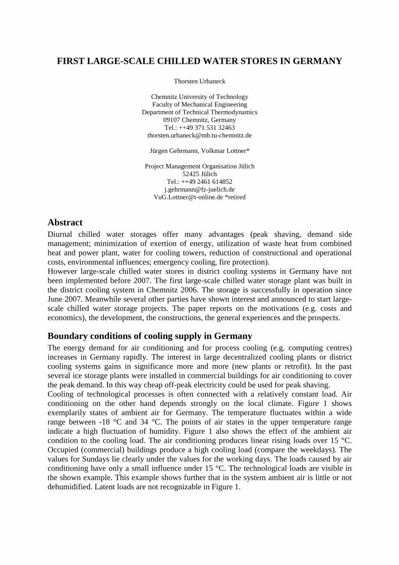
Boundary conditions of cooling supply in Germany The energy demand for air conditioning and for process cooling (e.g. computing centres) increases in Germany rapidly. The interest in large decentralized cooling plants or district cooling systems gains in significance more and more (new plants or retrofit). In the past several ice storage plants were installed in commercial buildings for air conditioning to cover the peak demand. In this way cheap off-peak electricity could be used for peak shaving. Cooling of technological processes is often connected with a relatively constant load. Air conditioning on the other hand depends strongly on the local climate. Figure 1 shows exemplarily states of ambient air for Germany. The temperature fluctuates within a wide range between -18 °C and 34 °C. The points of air states in the upper temperature range indicate a high fluctuation of humidity. Figure 1 also shows the effect of the ambient air condition to the cooling load. The air conditioning produces linear rising loads over 15 °C. Occupied (commercial) buildings produce a high cooling load (compare the weekdays). The values for Sundays lie clearly under the values for the working days. The loads caused by air conditioning have only a small influence under 15 °C. The technological loads are visible in the shown example. This example shows further that in the system ambient air is little or not dehumidified. Latent loads are not recognizable in Figure 1.
-20
0
20
40
0 2 4 6 8 10 12 14Absolute humidity [g/kg]
Tem
per
atur
e [°
C]
-20 -10 0 10 20 30 400
2000
4000
6000
Temperature [°C]
Loa
d [k
W]
0 2 4 6 8 10 12 140
2000
4000
6000
Absolute humidity [g/kg]
Load
[kW
]
Figure 1: Ambient air conditions and dependence of net load on air conditions and weekdays (blue: working days; on Saturdays: green; on Sundays: brown), example for Germany: district cooling in Chemnitz (23.07.2007- 07.01.2009), hourly mean values [1], [2]
0 2000 4000 6000 80000
1000
2000
3000
4000
5000
6000
Time [h]
Cap
acity
[kW
]
Cold water
Net loadAbsorption chiller, base load unitAbsorption chiller, base load unitAbsorption chiller, base load unitVapour compression chiller, peak load unitVapour compression chiller, peak load unitStorage, loadingStorage, unloading
0 2000 4000 6000 80000
1000
2000
3000
4000
5000
6000
Time [h]
Cap
acity
[kW
]
Energy input
Heat consumptionCurrent consumption
Net peak load
Peak load
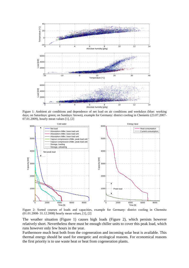
Figure 2: Sorted courses of loads and capacities, example for Germany: district cooling in Chemnitz (01.01.2008- 31.12.2008) hourly mean values, [1], [2]
The weather situation (Figure 1) causes high loads (Figure 2), which persists however relatively short. Nevertheless there must be enough chiller units to cover this peak load, which runs however only few hours in the year. Furthermore much heat both from the cogeneration and incoming solar heat is available. This thermal energy should be used for energetic and ecological reasons. For economical reasons the first priority is to use waste heat or heat from cogeneration plants.

Thermal driven chillers (absorption, adsorption, steam-jet) are available on the market. These chiller units possess however two crucial disadvantages: high investment costs (Figure 3) and high operation costs (higher need of electric power and water of recooling with open evaporation cooling towers). These factors prevent a wider distribution of the chillers. A solution of this problem is the application of a short-term cooling storage – here large chilled water store. Figure 4 shows the results of a feasibility study for German boundary conditions [3]. All variants with storage prove lower life cycle costs. Two storage variants are also under the investment costs with vapour compression chiller retrofit.
0
200
400
600
800
1000
1200
0 2000 4000 6000 8000 10000Cooling capacity [kW]
Spe
cific
cos
t [€
/kW
]
Vapour compression chiller without recooling
Vapour compression chiller with recooling
Single-effect absorption chiller without recooling
Single-effect absorption chiller with recooling (according to Schlott)
Double-effect absorption chiller without recooling
Double-effect absorption chillers with recooling (according to Schlott)
Figure 3: Specific investment costs in dependence of the cooling capacity for different chillers with and without recooling system [4]
0
200.000
400.000
600.000
800.000
1.000.000
1.200.000
Storage, GRP Storage, concrete Storage, steel Compression chiller
Cos
t [€
]
0
200.000
400.000
600.000
800.000
1.000.000
1.200.000
Cos
t [€
/a]
Investment cost
Demand cost
Life cycle cost
Figure 4: Comparison of costs between different variations on retrofitting of storages (3500 m³) or vapour compression chillers (state 2005); The costs for the steel storage variant refer to welded flat ground tanks by DIN 4119 [5]. The used thin-walled construction in the Chemnitz project [1] with screw joints in the wall section is described in DIN 18914 [6]. The steel storage variant and the developed hybrid construction shown in Figure 6 are not comparable for this reason.
The boundary conditions in the industry can deviate from the public or private facilities (e.g. purchase prices of fuels, waste heat from processes, supply of process steam) [7]. Compression chiller units are often to be found as basic load machines. The technological loads from process engineering possess a higher dependence compared with Figure 1. In addition, depending on the production they can vary strongly. These utility systems are statically insufficiently captured. Table 1 gives an overview of different types of chillers installed in supply networks. The number of thermal driven chillers is relatively small. The energy consumption for air conditioning amounts to in Germany approx. 21,000 GWh/a [8] and is hence much larger.
Table 1: District cooling systems (DC) in Germany with the use of district heating [9]
Year DC Nets Vapour compression chiller units
Sorption chiller units
Cooling capacity [MW]
Distribution [GWh/a]
2004 23 37 24 171 183
2005 27 44 31 184 187
2006 28 43 28 185 203
Consistent application of storage advantages Thermal energy storages possess many advantages. These advantages are not comprehensively used in many cases yet. The following points show the potential of short-term cooling storage.
1) Application of the storage concerning peak load shaving a. Reduction of the investment cost regarding new plants or retrofit (substitution
of chiller units) b. Avoid of peak loads covered by chiller units
2) Utilization of the storage with regard to the optimization of the cooling generation a. Chiller operation at optimal operating points
i. Increase of the Coefficient of Performance (COP) in comparison with the conventional operation
ii. More intensive night operation of the recooling system with low ambient temperatures and ambient air humidity (particularly important by open cooling towers)
iii. Load compensation by means of storage (flow rate offset), more stable utilization (fast reaction regarding net load variations, exclusive storage operation by low net loads)
iv. Lower specific consumption of auxiliary facilities (electric power, water)
b. Operation of the chiller units with boundary conditions of the energy supply in mind
i. Night operation with a small load factor of the power supply and low tariffs (in particular electric power)
ii. Cooling supply in connection with Demand Side Management (DSM), negative control energy
iii. Possible change between base load and peak load chiller units (changes of the preference), high flexibility during change of the boundary conditions
c. Emergency operation with storages (e.g. with minimal electric power) 3) Side effects
a. Simultaneous use as fire-extinguishing reserve with chilled water store (partitioning of the capital outlays)
b. Public-effective demonstration and pilot projects (visibility of the energy reserve)
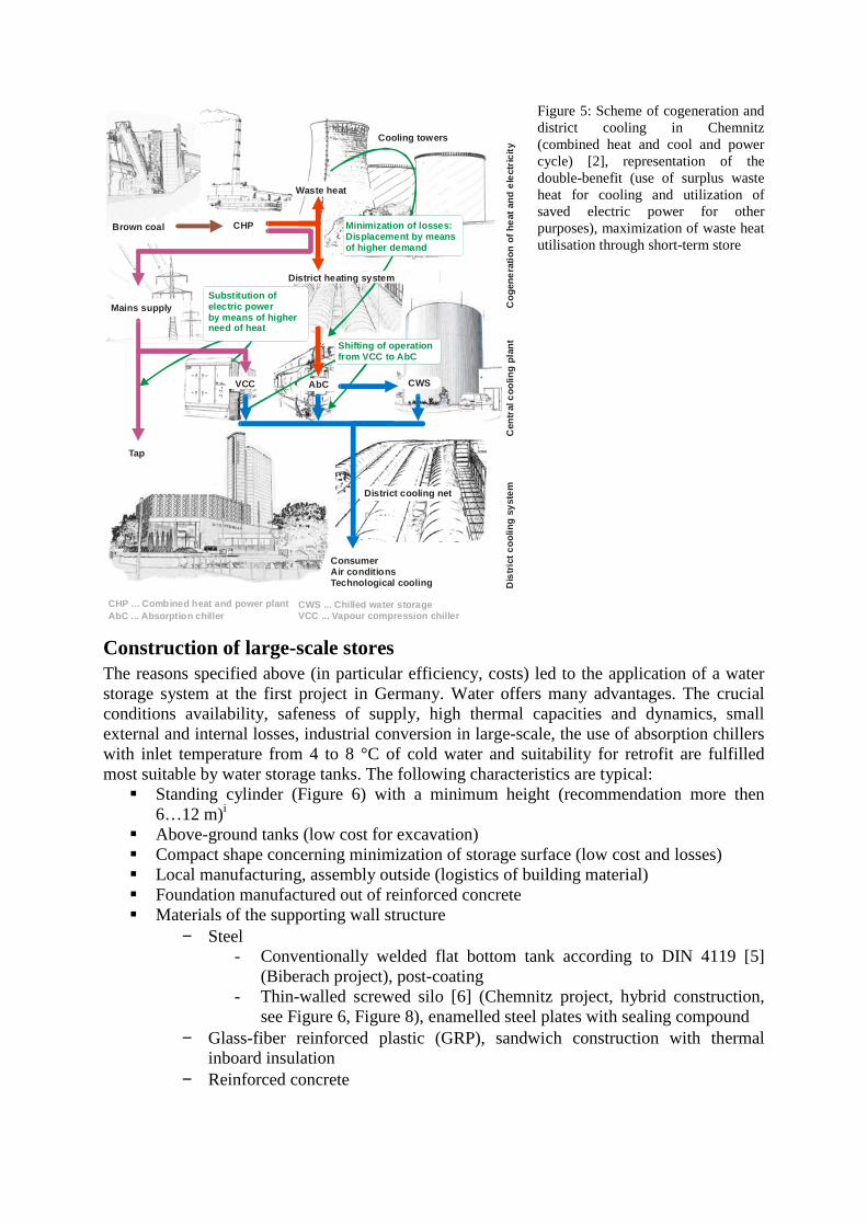
Figure 5 shows exemplarily the district cooling scheme in Chemnitz. Approx. 2 GWh/a more surplus heat can be used by means of storage utilization. Thereby 150 MWh/a electric power can be used otherwise. Further advantages of the operation and the experiences are described in [10].
CHP
CHP ... Combined heat and power plant
Cooling towers
Waste heat
Mains supply
Tap
Dis
tric
t c
oo
ling
sy
ste
mC
entr
al c
oo
ling
pla
nt
Co
gen
era
tio
n o
f h
eat
an
d e
lect
ric
ity
AbC
AbC ... Absorption chiller VCC ... Vapour compression chiller
VCC
District cooling net
ConsumerAir conditionsTechnological cooling
Brown coal Minimization of losses: Displacement by means of higher demand
Substitution ofelectric powerby means of higherneed of heat
Shifting of operationfrom VCC to AbC
CWS ... Chilled water storage
CWS
District heating system
Figure 5: Scheme of cogeneration and district cooling in Chemnitz (combined heat and cool and power cycle) [2], representation of the double-benefit (use of surplus waste heat for cooling and utilization of saved electric power for other purposes), maximization of waste heat utilisation through short-term store
Construction of large-scale stores The reasons specified above (in particular efficiency, costs) led to the application of a water storage system at the first project in Germany. Water offers many advantages. The crucial conditions availability, safeness of supply, high thermal capacities and dynamics, small external and internal losses, industrial conversion in large-scale, the use of absorption chillers with inlet temperature from 4 to 8 °C of cold water and suitability for retrofit are fulfilled most suitable by water storage tanks. The following characteristics are typical:
Standing cylinder (Figure 6) with a minimum height (recommendation more then 6…12 m)i
Above-ground tanks (low cost for excavation) Compact shape concerning minimization of storage surface (low cost and losses) Local manufacturing, assembly outside (logistics of building material) Foundation manufactured out of reinforced concrete Materials of the supporting wall structure
− Steel - Conventionally welded flat bottom tank according to DIN 4119 [5]
(Biberach project), post-coating - Thin-walled screwed silo [6] (Chemnitz project, hybrid construction,
see Figure 6, Figure 8), enamelled steel plates with sealing compound − Glass-fiber reinforced plastic (GRP), sandwich construction with thermal
inboard insulation − Reinforced concrete
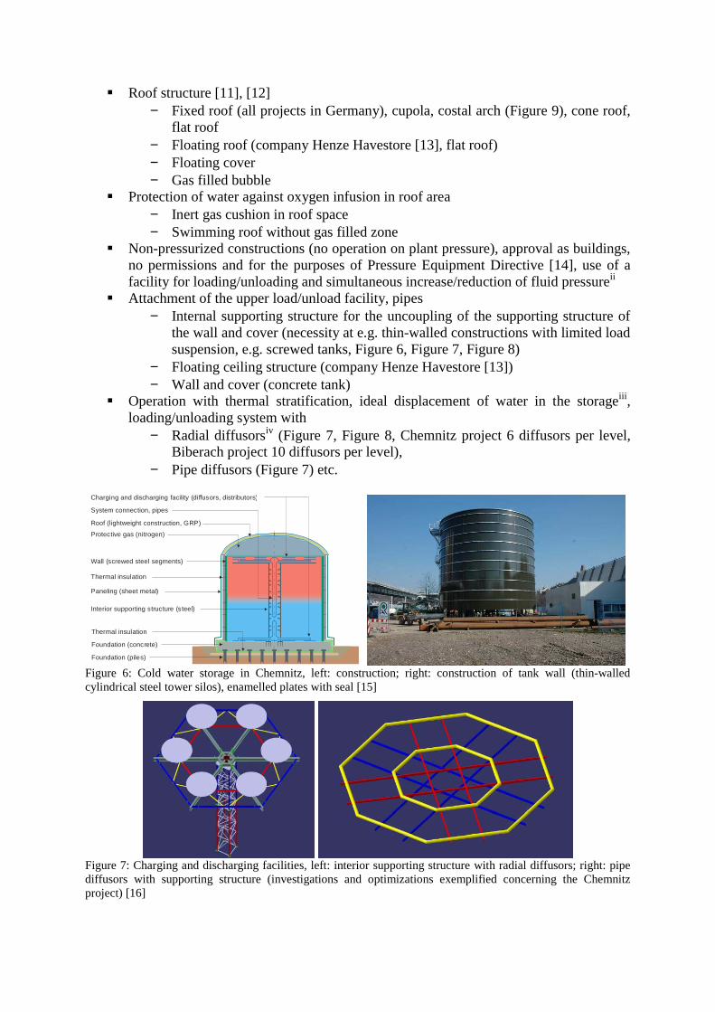
Roof structure [11], [12] − Fixed roof (all projects in Germany), cupola, costal arch (Figure 9), cone roof,
flat roof − Floating roof (company Henze Havestore [13], flat roof) − Floating cover − Gas filled bubble
Protection of water against oxygen infusion in roof area − Inert gas cushion in roof space − Swimming roof without gas filled zone
Non-pressurized constructions (no operation on plant pressure), approval as buildings, no permissions and for the purposes of Pressure Equipment Directive [14], use of a facility for loading/unloading and simultaneous increase/reduction of fluid pressureii
Attachment of the upper load/unload facility, pipes − Internal supporting structure for the uncoupling of the supporting structure of
the wall and cover (necessity at e.g. thin-walled constructions with limited load suspension, e.g. screwed tanks, Figure 6, Figure 7, Figure 8)
− Floating ceiling structure (company Henze Havestore [13]) − Wall and cover (concrete tank)
Operation with thermal stratification, ideal displacement of water in the storageiii, loading/unloading system with
− Radial diffusorsiv (Figure 7, Figure 8, Chemnitz project 6 diffusors per level, Biberach project 10 diffusors per level),
− Pipe diffusors (Figure 7) etc.
Roof (lightweight construction, GRP)
Protective gas (nitrogen)
Wall (screwed steel segments)
Paneling (sheet metal)
Interior supporting structure (steel)
Thermal insulation
Thermal insulation
Foundation (concrete)
Foundation (piles)
System connection, pipes
Charging and discharging facility (diffusors, distributors)
Figure 6: Cold water storage in Chemnitz, left: construction; right: construction of tank wall (thin-walled cylindrical steel tower silos), enamelled plates with seal [15]
Figure 7: Charging and discharging facilities, left: interior supporting structure with radial diffusors; right: pipe diffusors with supporting structure (investigations and optimizations exemplified concerning the Chemnitz project) [16]
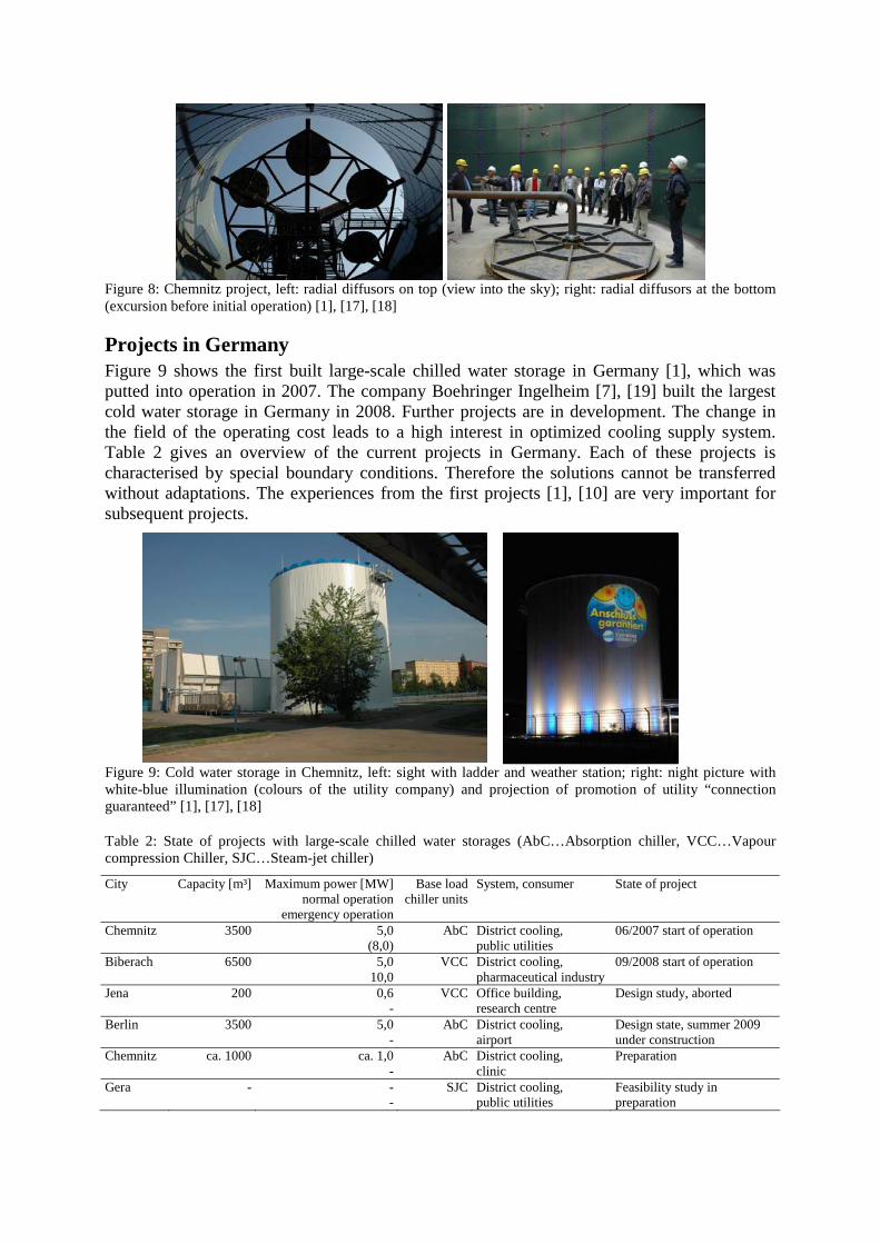
Figure 8: Chemnitz project, left: radial diffusors on top (view into the sky); right: radial diffusors at the bottom (excursion before initial operation) [1], [17], [18]
Projects in Germany Figure 9 shows the first built large-scale chilled water storage in Germany [1], which was putted into operation in 2007. The company Boehringer Ingelheim [7], [19] built the largest cold water storage in Germany in 2008. Further projects are in development. The change in the field of the operating cost leads to a high interest in optimized cooling supply system. Table 2 gives an overview of the current projects in Germany. Each of these projects is characterised by special boundary conditions. Therefore the solutions cannot be transferred without adaptations. The experiences from the first projects [1], [10] are very important for subsequent projects.
Figure 9: Cold water storage in Chemnitz, left: sight with ladder and weather station; right: night picture with white-blue illumination (colours of the utility company) and projection of promotion of utility “connection guaranteed” [1], [17], [18]
Table 2: State of projects with large-scale chilled water storages (AbC…Absorption chiller, VCC…Vapour compression Chiller, SJC…Steam-jet chiller)
City Capacity [m³]
Maximum power [MW] normal operation
emergency operation
Base load chiller units
System, consumer State of project
Chemnitz 3500 5,0 (8,0)
AbC District cooling, public utilities
06/2007 start of operation
Biberach 6500 5,0 10,0
VCC District cooling, pharmaceutical industry
09/2008 start of operation
Jena 200 0,6 -
VCC Office building, research centre
Design study, aborted
Berlin 3500 5,0 -
AbC
District cooling, airport
Design state, summer 2009 under construction
Chemnitz ca. 1000 ca. 1,0 -
AbC District cooling, clinic
Preparation
Gera - - -
SJC District cooling, public utilities
Feasibility study in preparation

Acknowledgements The presented results base on the project “Pilot project for optimization of large-scale supply systems based of CHCP by means of cool thermal energy storages”. The project (0327357B/C) has been funded by the Federal Ministry of Economics and Technology (BMWi), supervised by Project Management Organisation Jülich (PTJ). Project partners are Utility Company Chemnitz [2] und Chemnitz University of Technology. Furthermore the presented results base on projects within the co-operation with consulting service AIC Ingenieurgesellschaft für Bauplanung Chemnitz [17], pharmaceutical company Boehringer Ingelheim [19], store manufacturer Farmatic [15], store manufacturer Henze Havestore [13], piping company RAC Rohrleitungsbau Altchemnitz [18], consulting service BLS Energieplan [20], [21] and Utility Company Gera [22].
References [1] Urbaneck, T.: http://www-user.tu-chemnitz.de/~tur/ks2/pilotpr_ks.htm. Project website, 2005-2009.
[2] Stadtwerke Chemnitz AG: http://www.swc.de. 2009.
[3] Urbaneck, T.; Uhlig, U.; Platzer, B.; Schirmer, U.; Göschel T.; Zimmermann, D.: Machbarkeitsuntersuchung zur Stärkung der Kraft-Wärme-Kälte-Kopplung durch den Einsatz von Kältespeichern in großen Versorgungssystemen. Abschlussbericht BMWA-Forschungsvorhaben, Identifikation 0327357A, Chemnitz: Stadtwerke Chemnitz, TU Chemnitz, 2006. – ISBN 3-00-015770-0
[4] Lucas, K.; Gebhardt, M.; Kohl, H.; Steinrötter, T.: Preisatlas, Ableitung von Kostenfunktionen für Komponenten der rationellen Energienutzung. Stiftung Industrieforschung Forschungsvorhaben Nr. S 511, Institut für Energie- und Umwelttechnik e.V., Duisburg-Rheinhausen, 2002.
[5] Standard DIN 4119: Above-ground cylindric steel tank installations. 1980, retreated.
[6] Standard DIN 18914: Thin-walled cylindrical steel tower silos. 1985.
[7] Biffar, B.: Kraft-Wärme-Kälte-Kopplung in der Industrie am Beispiel des Standorts Biberach. Internationales Fachforum für Energie, Chemnitz, 11.09.2008.
[8] Franzke, U.: Klima- und Kältetechnik in der Prozessanwendung. ki Luft- und Kältetechnik 07/2005. – ISSN 0945-0459
[9] Arbeitsgemeinschaft für Wärme und Heizkraftwirtschaft - AGFW - e. V. (Hrsg.): Hauptbericht der Fernwärmeversorgung 2006.
[10] Urbaneck, T.; Barthel, U.; Uhlig, U.; Göschel, T.: Only cold water?! - The success with the First Large-Scale Cold Water Store in Germany. Effstock, 11th International Conference on Thermal Energy Storage, Stockholm (Sweden), 2009.
[11] Hampe, E.: Flüssigkeitsbehälter. Bd. 1 Grundlagen Berlin: Verlag für Bauwesen, 1979.
[12] Hampe, E.: Flüssigkeitsbehälter. Bd. 2 Bauwerke Berlin: Verlag für Bauwesen, 1982.
[13] Henze-Harvestore GmbH: http://www.harvestore.de. 2009.
[14] Pressure Equipment Directive 97/23/EC (PED) of the European Union.
[15] Farmatic Anlagenbau GmbH: http://www.farmatic.de. 2009.
[16] Maier, J.: Konstruktive Optimierung eines inneren Tragwerkes für große Kaltwasserspeicher. Studienarbeit, TU Chemnitz, Professur Technischer Thermodynamik, 2007.
[17] AIC Ingenieurgesellschaft für Bauplanung Chemnitz GmbH: http://www.aic-chemnitz.de. 2009.
[18] RAC-Rohrleitungsbau Altchemnitz GmbH: http://www.rac-bau.de. 2009.
[19] Boehringer Ingelheim Pharma GmbH & Co. KG: http://www.boehringer-ingelheim.de. 2009.
[20] BLS Energieplan: http://www.bls-energieplan.de. 2009.
[21] Airport Berlin Brandenburg International BBI: http://www.berlin-airport.de. 2009.
[22] Energieversorgung Gera GmbH: http://www.energieversorgung-gera.de. 2009.
[23] Urbaneck, T.; Uhlig, U.: Kaltwasserspeicher mit Schichtungsbetrieb – Analyse des Speicherverhaltens. ki Luft- und Kältetechnik Hüthig 44. Jg. (2008) Heft 07-08 S. 32-37. – ISSN 0945-0459
i Lying cylinders have problems with the thermal stratification (study Jena project, lying tank with cells in the building). ii Electric power for pumps is relatively small. iii The use of diaphragms is at present of topical interest. iv The results concerning the thermal stratification are satisfying [23].