first use of gfrp bars as reinforcement for continuous ... · pdf filecrcp is a reinforced...
TRANSCRIPT
Fourth International Conference on FRP Composites in Civil Engineering (CICE2008) 22-24July 2008, Zurich, Switzerland
- 1 -
Keywords: GFRP, CRCP, Pavement, Design, Construction, Instrumentation, Concrete, Steel
1 INTRODUCTION
Many distress occurring in concrete structures are attributed to the corrosion of steel reinforce-ment, a condition to which steel-reinforced continuously reinforced concrete pavement (CRCP) is typically subjected. According to a CRCP performance report, corrosion has been a major de-teriorative factor for CRCPs in harsh environment as in Canada and northern states of USA, causing delamination, spalling, and steel rupture (Neff and Ray, 1986). Therefore, glass fiber re-inforced polymer (GFRP) bars which are increasingly gaining attention for structure application because of their non-corrosiveness and high longitudinal strength, light weight, and nonmag-netic quality, can also be viable alternatives to steel reinforcing bars for CRCP. CRCP is a reinforced concrete pavement where the longitudinal reinforcement is continuous for its length. It does not require any contraction joints (considered to be the week-point of jointed concrete pavements). Transverse cracks are allowed to form but are held tightly together with the continuous longitudinal reinforcement. Considering the success of the CRCP in USA and some European countries and for its superior long-term performance, the Ministry of Transpor-tation of Quebec (MTQ) investigated the use of CRCP in 2000 for the first time in Canada in a test project (2 km long) on Highway 13 in Laval (Montreal, Quebec). However, the major chal-lenge facing the CRCP designer is its long-term behavior when subjected to Quebec whether. Some core samples taken in 2005 at the cracks of the first CRCP constructed in 2000 showed corrosion in the longitudinal steel reinforcement. Several techniques were proposed to solve this problem including epoxy coating of the reinforcing bar and galvanized steel bars; however, nei-ther of these techniques has proven to be cost-effective or a long-term solution (Thébeau 2002). In an effort to find out the most durable solution, it has been suggested to use non-corrodible GFRP bars in the CRCP, and eventually replace all the steel bars with GFRP bars. This material
First Use of GFRP Bars as Reinforcement for Continuous Reinforced Concrete Pavement
B. Benmokrane1, M. Eisa1, S. El-Gamal1, E. El-Salakawy2, and D. Thebeau3
1Civil Engineering Department, University of Sherbrooke, Quebec, Canada 2Civil Engineering Department, University of Manitoba, Manitoba, Canada 3Ministry of Transportation of Quebec, Quebec City, Canada
ABSTRACT: The corrosion resistance characteristics of glass fiber reinforced polymer (GFRP) bars make them a promising substitute for conventional steel reinforcing bars in Continuously Reinforced Concrete Pavements (CRCP). However, GFRP bars have never been used in a CRCP highway exhibiting regular traffic. This paper presents the steps that were followed in order to adapt the design and construction of eighteen full-scale CRCP slabs on Highway 40 East (Montréal) reinforced with GFRP bars. The test slabs represent a 150 m long section of the highway with the full width. Each slab in the test section is 25 m long and 3.7 m wide. The eighteen slabs were designed and constructed to investigate the different parameters known to affect the performance of such CRCP slabs. Varieties of sensors were installed in this project in order to monitor the early-age behavior, repeated load effects, and environmental conditions on the performance of the CRCP slabs. This includes different types of electrical resistance strain gauges and fiber optic sensors (FOS) to measure reinforcement and concrete strains. In addition, thermocouples and FOS have been used for temperature measurements. Design concepts, con-struction details, properties of used materials, early-age behavior and preliminary results of this first use of GFRP bars in CRCP slabs are presented in this paper.

- 2 -
has been used successfully in many industrial applications and, more recently, has been intro-duced in jointed reinforced concrete pavement (JRCP), but it has never been studied on a traf-ficked highway in CRCP.
Hence, the MTQ (Pavement Division) and the University of Sherbrooke initiated a pioneer re-search test project in late 2006. This project included design and construction of eighteen full-scale CRCP slabs reinforced with GFRP and steel bars over an area of 150 × 11.3 m in three lanes of Highway 40 East (Montréal). The eighteen slabs were designed and constructed to in-vestigate the different parameters known to affect the performance of such CRCP slabs. The main objective of this project is to solve the potential problem of corrosion of the CRCP with steel, especially at transverse cracks, by replacing the steel bars with GFRP bars which will in-crease the longevity of these pavements, and therefore, reduce maintenance requirements. Moreover, this research project will implement the technology of GFRP reinforcing bars as well as demonstrate their ability to meet all CRCP requirements. This article summarizes the design concepts, construction details, properties of used materials, early-age behavior and preliminary results of the CRCP slabs almost one year following the completion of construction. Through-out this article, GFRP-CRCP will refer to the continuously reinforced concrete pavement system with glass fiber reinforced polymer bars.
2 DESIGN OF GFRP-CRCP SLABS
The design of CRCP consists of two primary components according to TxDOT (2004): pave-ment thickness and longitudinal reinforcement ratio. The thickness of the CRCP slabs of the test project was taken similar to the adjacent CRCP reinforced with steel (280 mm) which was con-structed in 2006 directly before the construction of the test project. Only in two slabs of the test project, the thickness was increased to 350 mm as a parameter in the study. To determine the required GFRP reinforcement, four equations were used to calculate the pro-posed longitudinal reinforcement ratio: Vetter’s 1933, AASHTO 1972, USDT 1996, and ACI 440.1R-06. Although the first three were proposed for CRCP reinforced with steel, they were used in this study through changing the input parameters to be compatible with GFRP proper-ties. The only equation proposed for slabs on ground reinforced with GFRP bars was the ACI 440.1R-06 equation, however; there is no experimental work to support it. In light of the previ-ous approaches and equations, 1.2 % was chosen to be the proposed reinforcement ratio. More-over, six reinforcement ratios ranging from 0.78 % to 1.6 % were used to assure the proper lon-gitudinal reinforcement ratio for GFRP-CRCP slabs.
3 DESCRIPTION OF HIGHWAY-40 TEST PROJECT
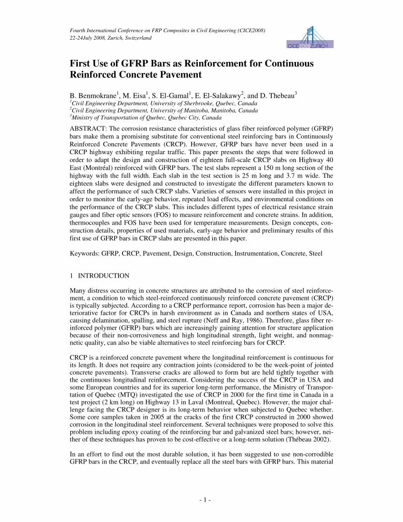
Highway 40 East consists of 3 lanes, 3.7 m each. The test slabs represent a 150 m long section of the highway with the full width. Fifteen (15) slab portions of the three-lane were reinforced with GFRP bars. In addition to these 15 slab portions, 3 additional slab portions were con-structed and reinforced using galvanized steel bars for comparison purposes. The width of 11.1 m constitutes the adjacent three lanes of the highway (3 lanes × 3.7 m in width). Each slab por-tion has the dimensions of 25 m long and 3.7 m wide. Six slab portions were implemented per each lane (see Figure 1). The representative length of 25 m was carefully chosen along which reliable conclusion could be drawn on the behavior of the entire test area. In-between distances of 3 m in the longitudinal direction were used as transition zones to over-lap the GFRP rein-forcement of the adjacent portions. The area of the project constitutes the far-end of a 9-km part of Highway 40 East in Montreal constructed (May-September 2006) using the CRCP system re-inforced with galvanized steel. Details about section layout and basic design parameters are pre-sented in Figure (1) and can be further reviewed in Eisa et al. (2007).
- 3 -
Figure 1. Layout and basic design parameters of test sections
4 CRCP CONSTRUCTION AND MATERIAL PROPERTIES
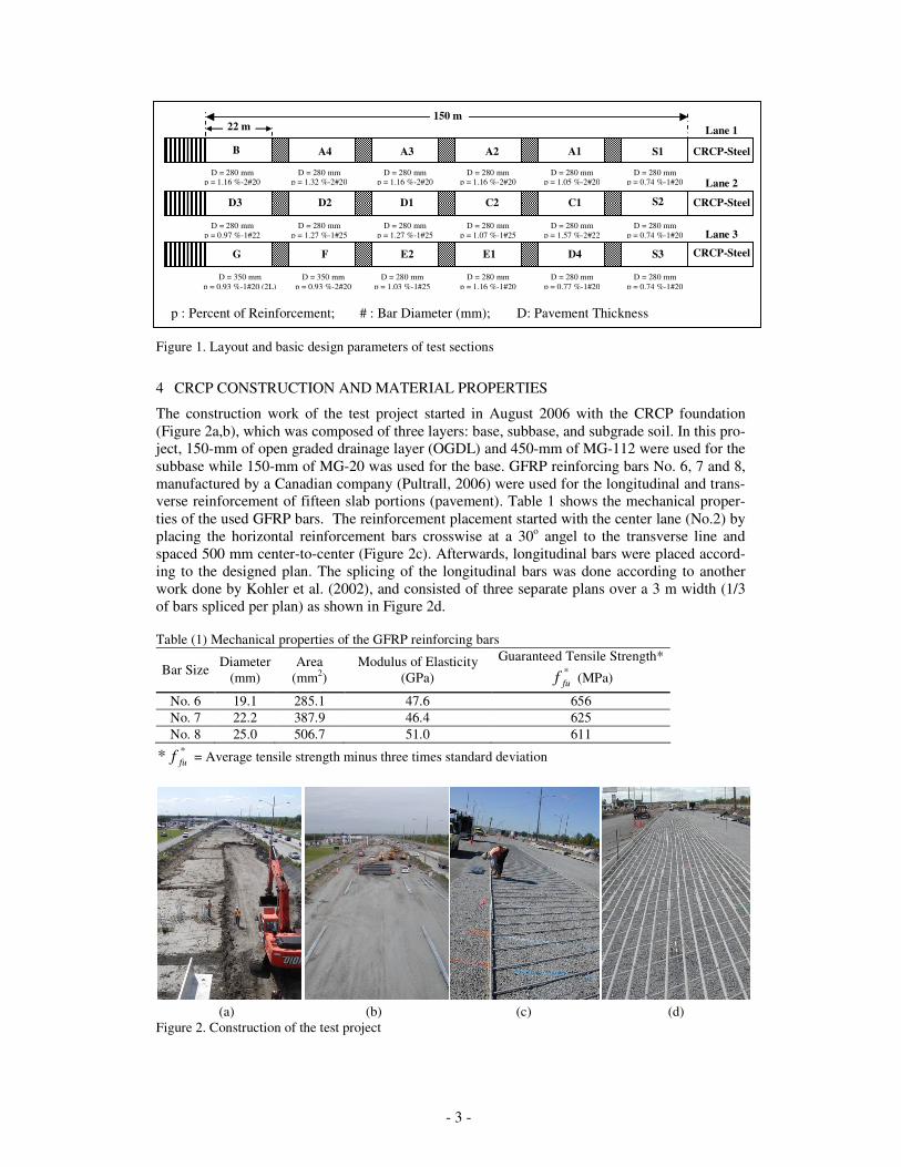
The construction work of the test project started in August 2006 with the CRCP foundation (Figure 2a,b), which was composed of three layers: base, subbase, and subgrade soil. In this pro-ject, 150-mm of open graded drainage layer (OGDL) and 450-mm of MG-112 were used for the subbase while 150-mm of MG-20 was used for the base. GFRP reinforcing bars No. 6, 7 and 8, manufactured by a Canadian company (Pultrall, 2006) were used for the longitudinal and trans-verse reinforcement of fifteen slab portions (pavement). Table 1 shows the mechanical proper-ties of the used GFRP bars. The reinforcement placement started with the center lane (No.2) by placing the horizontal reinforcement bars crosswise at a 30o angel to the transverse line and spaced 500 mm center-to-center (Figure 2c). Afterwards, longitudinal bars were placed accord-ing to the designed plan. The splicing of the longitudinal bars was done according to another work done by Kohler et al. (2002), and consisted of three separate plans over a 3 m width (1/3 of bars spliced per plan) as shown in Figure 2d. Table (1) Mechanical properties of the GFRP reinforcing bars
Bar Size Diameter (mm)
Area (mm2)
Modulus of Elasticity (GPa)
Guaranteed Tensile Strength* *fuf (MPa)
No. 6 19.1 285.1 47.6 656 No. 7 22.2 387.9 46.4 625 No. 8 25.0 506.7 51.0 611
** fuf = Average tensile strength minus three times standard deviation
(a) (b) (c) (d)
Figure 2. Construction of the test project
A1 B
150 m
D = 280 mm p = 1.16 %-2#20
D = 280 mm p = 1.32 %-2#20
D = 280 mm p = 1.16 %-2#20
D = 280 mm p = 1.16 %-2#20
D = 280 mm p = 1.05 %-2#20
D = 280 mm p = 0.74 %-1#20
A4 A3 A2 S1
22 m
CRCP-Steel
D3
D = 280 mm p = 0.97 %-1#22
D = 280 mm p = 1.27 %-1#25
D = 280 mm p = 1.27 %-1#25
D = 280 mm p = 1.07 %-1#25
D = 280 mm p = 1.57 %-2#22
D = 280 mm p = 0.74 %-1#20
D2 D1 C2 C1 S2
G
D = 350 mm p = 0.93 %-1#20 (2L)
D = 350 mm p = 0.93 %-2#20
D = 280 mm p = 1.03 %-1#25
D = 280 mm p = 1.16 %-1#20
D = 280 mm p = 0.77 %-1#20
D = 280 mm p = 0.74 %-1#20
F E2 E1 D4 S3
CRCP-Steel
CRCP-Steel
Lane 1
Lane 2
Lane 3
p : Percent of Reinforcement; # : Bar Diameter (mm); D: Pavement Thickness

- 4 -
Moreover, according to the MTQ standards, galvanized steel bars No. 6 and No. 5, respectively, were used for longitudinal and transverse reinforcement of the three slab portions reinforced with steel (S1, S2 and S3). Concrete type IIIA was used for the demonstration project according to MTQ specifications as listed in Table 2, with a maximum water to cement ratio of 0.45 and a slump range between 40 to 20 mm. The basic mix design for this type consists of 20 mm coarse aggregates and 340 kg/m3 of Lafarge Tercem-3000 blended silica fume/slag cement. The target compression strength for this mix was 35 MPa at 28-days. Table 2. Theoretical mix design for the used concrete
Concrete Type
Cement content (kg/m3)
Water/Cement Ratio
Aggregate size (mm)
Air content (%)
Air Entraining Ad-mixture
( ml/100 kg) Type IIIA 340 0.45 (10-20) & (5-14) Granite 5-8 60.00
The contractor had a mixing plant set up near the job, and the concrete arrived at the project in flatbed trucks. A paving train with a slipform paver features a GOMACO-GT6300 operating at a width 3.7-m was used to cast the concrete as shown in Figure 3. The first day of concrete placement was September 26, 2006, starting with the center lane. Later, the concrete placement was done for the left lane and the right lane in October 2nd and 6th, respectively. The concrete production was varied between 60 to 90 m3 per hour for the mainline paving casting a total quantity of 564 m3 for the three lanes in this project. The highway 40 including the demonstra-tion sections was opened to traffic at the end of October 2006.
Figure 3. Concrete casting
5 INSTRUMENTATION
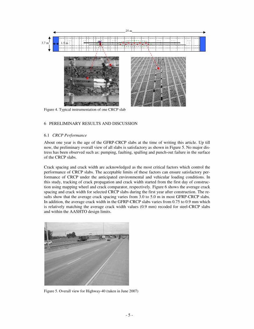
Varieties of sensors were installed in this project in order to monitor the early-age behavior of the CRCP slabs and judge their performance later in light of the expected long term results. This included reinforcement and concrete electrical strain gages for measuring strains in reinforce-ment (steel & GFRP) and concrete, respectively. The number of reinforcement strain gauges (CEA-Series) varied from 5 to 11 strain gauges per slab and the number of concrete strain gauges (EGP-Series) varied from 3 to 6 gauges per slab. The locations of theses gauges were chosen to be at the middle of the CRCP slabs to increase the possibility of catching transverse cracks at the gauges location, typical instrumentation of one CRCP slab is shown in Figure 4. In addition, thermocouples (Type-T-Copper-Constant) were used for temperature measurements inside the concrete. Fiber Optic Sensors (FOS) were used also in this project for comparison with electrical gauges and for the long term monitoring of the CRCP.
- 5 -
Figure 4. Typical instrumentation of one CRCP slab
6 PERELIMINARY RESULTS AND DISCUSSION
6.1 CRCP Performance
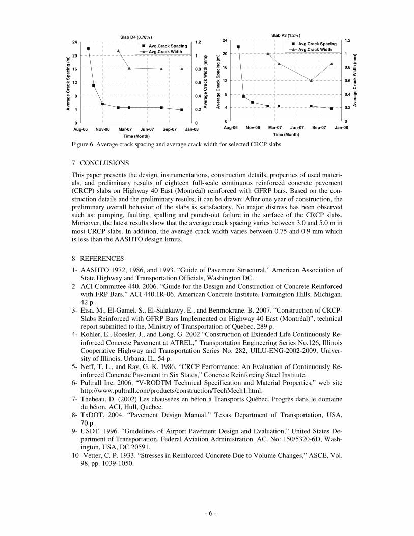
About one year is the age of the GFRP-CRCP slabs at the time of writing this article. Up till now, the preliminary overall view of all slabs is satisfactory as shown in Figure 5. No major dis-tress has been observed such as: pumping, faulting, spalling and punch-out failure in the surface of the CRCP slabs. Crack spacing and crack width are acknowledged as the most critical factors which control the performance of CRCP slabs. The acceptable limits of these factors can ensure satisfactory per-formance of CRCP under the anticipated environmental and vehicular loading conditions. In this study, tracking of crack propagation and crack width started from the first day of construc-tion using mapping wheel and crack comparator, respectively. Figure 6 shows the average crack spacing and crack width for selected CRCP slabs during the first year after construction. The re-sults show that the average crack spacing varies from 3.0 to 5.0 m in most GFRP-CRCP slabs. In addition, the average crack width in the GFRP-CRCP slabs varies from 0.75 to 0.9 mm which is relatively matching the average crack width values (0.9 mm) recoded for steel-CRCP slabs and within the AASHTO design limits.
Figure 5. Overall view for Highway-40 (taken in June 2007)
25 m
3.7 m 1.5 m
- 6 -
Slab D4 (0.78%)
0
4
8
12
16
20
24
Aug-06 Nov-06 Mar-07 Jun-07 Sep-07 Jan-08
Time (Month)
Ave
rage
Cra
ck S
pac
ing
(m)
0
0.2
0.4
0.6
0.8
1
1.2
Ave
rage
Cra
ck W
idth
(mm
)
Avg.Crack SpacingAvg.Crack Width
Slab A3 (1.2%)
0
4
8
12
16
20
24
Aug-06 Nov-06 Mar-07 Jun-07 Sep-07 Jan-08
Time (Month)
Ave
rage
Cra
ck S
paci
ng (m
)
0
0.2
0.4
0.6
0.8
1
1.2
Ave
rage
Cra
ck W
idth
(mm
)
Avg.Crack SpacingAvg.Crack Width
Figure 6. Average crack spacing and average crack width for selected CRCP slabs
7 CONCLUSIONS
This paper presents the design, instrumentations, construction details, properties of used materi-als, and preliminary results of eighteen full-scale continuous reinforced concrete pavement (CRCP) slabs on Highway 40 East (Montréal) reinforced with GFRP bars. Based on the con-struction details and the preliminary results, it can be drawn: After one year of construction, the preliminary overall behavior of the slabs is satisfactory. No major distress has been observed such as: pumping, faulting, spalling and punch-out failure in the surface of the CRCP slabs. Moreover, the latest results show that the average crack spacing varies between 3.0 and 5.0 m in most CRCP slabs. In addition, the average crack width varies between 0.75 and 0.9 mm which is less than the AASHTO design limits.
8 REFERENCES
1- AASHTO 1972, 1986, and 1993. “Guide of Pavement Structural.” American Association of State Highway and Transportation Officials, Washington DC.
2- ACI Committee 440. 2006. “Guide for the Design and Construction of Concrete Reinforced with FRP Bars.” ACI 440.1R-06, American Concrete Institute, Farmington Hills, Michigan, 42 p.
3- Eisa. M., El-Gamel. S., El-Salakawy. E., and Benmokrane. B. 2007. “Construction of CRCP-Slabs Reinforced with GFRP Bars Implemented on Highway 40 East (Montréal)”, technical report submitted to the, Ministry of Transportation of Quebec, 289 p.
4- Kohler, E., Roesler, J., and Long, G. 2002 “Construction of Extended Life Continuously Re-inforced Concrete Pavement at ATREL,” Transportation Engineering Series No.126, Illinois Cooperative Highway and Transportation Series No. 282, UILU-ENG-2002-2009, Univer-sity of Illinois, Urbana, IL, 54 p.
5- Neff, T. L., and Ray, G. K. 1986. “CRCP Performance: An Evaluation of Continuously Re-inforced Concrete Pavement in Six States,” Concrete Reinforcing Steel Institute.
6- Pultrall Inc. 2006. “V-RODTM Technical Specification and Material Properties,” web site http://www.pultrall.com/products/construction/TechMech1.html.
7- Thebeau, D. (2002) Les chaussées en béton à Transports Québec, Progrès dans le domaine du béton, ACI, Hull, Québec.
8- TxDOT. 2004. “Pavement Design Manual.” Texas Department of Transportation, USA, 70 p.
9- USDT. 1996. “Guidelines of Airport Pavement Design and Evaluation,” United States De-partment of Transportation, Federal Aviation Administration. AC. No: 150/5320-6D, Wash-ington, USA, DC 20591.
10- Vetter, C. P. 1933. “Stresses in Reinforced Concrete Due to Volume Changes,” ASCE, Vol. 98, pp. 1039-1050.