flanged ball valves - metsovalveproducts.metso.com/documents/jamesbury/imos/en/imo-227en.… ·...
TRANSCRIPT
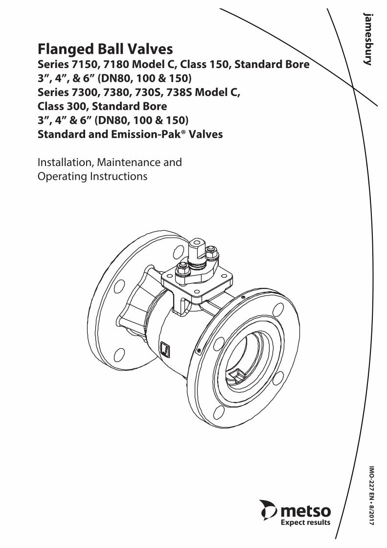
Flanged Ball ValvesSeries 7150, 7180 Model C, Class 150, Standard Bore3”, 4”, & 6” (DN80, 100 & 150)Series 7300, 7380, 730S, 738S Model C, Class 300, Standard Bore3”, 4” & 6” (DN80, 100 & 150)Standard and Emission-Pak® Valves
Installation, Maintenance and Operating Instructions
IMO
-227 EN • 8/2017

Table of Contents1 GENERAL . . . . . . . . . . . . . . . . . . . . . . . . . . . . . . . . . . . . 3
1.1 Scope of the Manual . . . . . . . . . . . . . . . . . . . . . . . . .31.2 Valve Markings . . . . . . . . . . . . . . . . . . . . . . . . . . . . . .31.3 Safety Precautions . . . . . . . . . . . . . . . . . . . . . . . . . . .3
2 TRANSPORTATION AND STORAGE . . . . . . . . . . . 4
3 INSTALLATION . . . . . . . . . . . . . . . . . . . . . . . . . . . . . . 43.1 General. . . . . . . . . . . . . . . . . . . . . . . . . . . . . . . . . . . . . .43.2 Installing in the Pipeline . . . . . . . . . . . . . . . . . . . . .43.3 Valve Insulation . . . . . . . . . . . . . . . . . . . . . . . . . . . . .43.4 Actuator. . . . . . . . . . . . . . . . . . . . . . . . . . . . . . . . . . . . .43.5 Commissioning. . . . . . . . . . . . . . . . . . . . . . . . . . . . . .5
4 MAINTENANCE . . . . . . . . . . . . . . . . . . . . . . . . . . . . . . 54.1 General. . . . . . . . . . . . . . . . . . . . . . . . . . . . . . . . . . . . . .54.2 Actuated Valve . . . . . . . . . . . . . . . . . . . . . . . . . . . . . .54.3 Manual Valve - with Handle . . . . . . . . . . . . . . . . . .54.4 Disassembly - Bare Stem Valves . . . . . . . . . . . . . .54.5 Checking Parts - Emission-Pak Valve . . . . . . . . . .64.6 Checking Parts . . . . . . . . . . . . . . . . . . . . . . . . . . . . . .74.7 Assembly - Bare Stem Valves . . . . . . . . . . . . . . . . .74.8 Assembly - Emission-Pak Valve . . . . . . . . . . . . . . .94.9 Testing the Valve . . . . . . . . . . . . . . . . . . . . . . . . . . 11
5 HANDLE MOUNTING . . . . . . . . . . . . . . . . . . . . . . . . 11
6 STEM EXTENSION MOUNTING . . . . . . . . . . . . . . . 11
7 ACTUATOR MOUNTING . . . . . . . . . . . . . . . . . . . . . 117.1 General. . . . . . . . . . . . . . . . . . . . . . . . . . . . . . . . . . . . 117.2 Valve Preparation. . . . . . . . . . . . . . . . . . . . . . . . . . 127.3 Bracket Preparation. . . . . . . . . . . . . . . . . . . . . . . . 127.4 Bracket Attachment to Valve . . . . . . . . . . . . . . . 137.5 Actuator versus Valve Position . . . . . . . . . . . . . 137.6 Coupling to Actuator . . . . . . . . . . . . . . . . . . . . . . 137.7 Bracket attachment to Actuator . . . . . . . . . . . . 137.8 Open / Close Position Adjustment. . . . . . . . . . 14
8 SERVICE / SPARE PART . . . . . . . . . . . . . . . . . . . . . . 15
Subject to change without notice.All trademarks are property of their respective owners.
2 IMO-227 EN
IMO 8/17
READ THESE INSTRUCTIONS FIRST!
These instructions provide information about safe handling and operation of the valve.If you require additional assistance, please contact the manufacturer or manufacturer’s representative.Addresses and phone numbers are printed on the back cover.See also www.metso.com/valves for the latest documentation.
SAVE THESE INSTRUCTIONS!

1 GENERAL
1 .1 Scope of the Manual
This instruction manual contains important information regarding the installation, operation and maintenance of the Jamesbury® 3”, 4” & 6” (DN80, 100 & 150) ASME Class 150; and the 3”, 4” & 6” (DN80, 100 & 150) ASME Class 300, Standard Bore, Non-trunnion Series 7000 Model C standard and Emission-Pak Flanged Ball Valves. Please read these instructions carefully and save them for future reference.
WARNING:
AS THE USE OF THE VALVE IS APPLICATION SPECIFIC, A NUMBER OF FACTORS SHOULD BE TAKEN INTO ACCOUNT WHEN SELECTING A VALVE FOR A GIVEN APPLICATION. THEREFORE, SOME OF THE SITUATIONS IN WHICH THE VALVES ARE USED ARE OUTSIDE THE SCOPE OF THIS MANUAL.
IF YOU HAVE ANY QUESTIONS CONCERNING THE USE, APPLICA-TION OR COMPATIBILITY OF THE VALVE WITH THE INTENDED SER-VICE, CONTACT METSO FOR MORE INFORMATION.
WARNING:
JAMESBURY EMISSION-PAK BALL VALVES WITH THE “LEAK-OFF” OPTION ARE SHIPPED FROM THE FACTORY WITH A PLASTIC PIPE PLUG INSERTED INTO THE “LEAK-OFF” PORT. THIS PLASTIC PIPE PLUG’S ONLY PURPOSE IS TO PREVENT CONTAMINATION FROM ENTERING THE PORT. THE PLASTIC PIPE PLUG WILL NOT RETAIN ANY VALVE PRESSURE AND MUST BE REMOVED PRIOR TO PRES-SURIZING THE VALVE. FAILURE TO REMOVE THE PLASTIC PIPE PLUG AND REPLACE IT WITH A SUITABLE PRESSURE RETAINING CONNEC-TION MAY RESULT IN DAMAGE OR PERSONAL INJURY!
1 .2 Valve Markings
The valve has an identification plate attached to the pipe-line flange (see Figure 1).
Figure 1 Identification plate
Identification markings:1 Ball/Stem material2 Valve catalog code 3 Seat Material4 Body Material5 Maximum operating pressure6 Maximum/minimum shut-off pressure/temperature7 Approvals/Special Service marking8 Model9 Assembly date
1 .3 Safety Precautions
WARNING:
DO NOT EXCEED THE VALVE PERFORMANCE LIMITATIONS!
EXCEEDING THE PRESSURE OR TEMPERATURE LIMITATIONS MARKED ON THE VALVE IDENTIFICATION PLATE MAY CAUSE DAM-AGE AND LEAD TO UNCONTROLLED PRESSURE RELEASE. DAMAGE OR PERSONAL INJURY MAY RESULT.
WARNING:
SEAT AND BODY RATINGS!
THE PRACTICAL AND SAFE USE OF THIS PRODUCT IS DETERMINED BY BOTH THE SEAT AND BODY RATINGS. READ THE IDENTIFICATION PLATE AND CHECK BOTH RATINGS. THIS PRODUCT IS AVAILABLE WITH A VARIETY OF SEAT MATERIALS. SOME OF THE SEAT MATERIALS HAVE PRESSURE RATINGS THAT ARE LESS THAN THE BODY RATINGS. ALL OF THE BODY AND SEAT RATINGS ARE DEPENDENT ON VALVE TYPE AND SIZE, SEAT MATERIAL, AND TEMPERATURE. DO NOT EXCEED THESE RATINGS!
WARNING:
BEWARE OF BALL MOVEMENT!
KEEP HANDS, OTHER PARTS OF THE BODY, TOOLS AND OTHER OBJECTS OUT OF THE OPEN FLOW PORT. LEAVE NO FOREIGN OBJECTS INSIDE THE PIPELINE. WHEN THE VALVE IS ACTUATED, THE BALL FUNCTIONS AS A CUTTING DEVICE. DISCONNECT ANY PNEUMATIC SUPPLY LINES, ANY ELECTRICAL POWER SOURCES AND MAKE SURE SPRINGS IN SPRING-RETURN ACTUATORS ARE IN THE FULL EXTENDED/RELAXED STATE BEFORE PERFORMING ANY VALVE MAINTENANCE. FAILURE TO DO THIS MAY RESULT IN DAM-AGE OR PERSONAL INJURY!
WARNING:
WHEN HANDLING THE VALVE OR VALVE/ACTUATOR ASSEMBLY, TAKE ITS WEIGHT INTO ACCOUNT!
NEVER LIFT THE VALVE OR VALVE/ACTUATOR ASSEMBLY BY THE ACTUATOR, POSITIONER, LIMIT SWITCH OR THEIR PIPING. PLACE LIFTING DEVICES SECURELY AROUND THE VALVE BODY. FAILURE TO FOLLOW THESE INSTRUCTIONS MAY RESULT IN DAMAGE OR PERSONAL INJURY FROM FALLING PARTS (SEE FIGURE 2).
IMO-227 EN 3
IMO 8/17

CORRECT
WRONG
Figure 2 Lifting the valve
2 TRANSPORTATION AND STORAGE
Check the valve and the accompanying devices for any damage that may have occurred during transport.
Store the valve carefully. Storage indoors in a dry place is recommended.
Do not remove the flow port protectors until installing the valve.
Move the valve to its intended location just before instal-lation.
The valve is usually delivered in the closed position.
3 INSTALLATION
3 .1 General
Remove the flow port protectors and check that the valve is clean inside. Clean valve if necessary.
Flush the pipeline carefully before installing the valve. Foreign objects, such as sand or pieces of welding elec-trodes, will damage the ball and seats.
3 .2 Installing in the pipeline
WARNING:
THE VALVE SHOULD BE TIGHTENED BETWEEN FLANGES USING APPROPRIATE GASKETS AND FASTENERS COMPATIBLE WITH THE APPLICATION, AND IN COMPLIANCE WITH APPLICABLE PIPING CODES AND STANDARDS. CENTER THE FLANGE GASKETS CARE-FULLY WHEN FITTING THE VALVE BETWEEN FLANGES. DO NOT ATTEMPT TO CORRECT PIPELINE MISALIGNMENT BY MEANS OF FLANGE BOLTING!
The valve may be installed in any position and offers tight-ness in both directions. It is recommended, however, that the valve be installed with the insert facing upstream. It is not recommended to install the valve with the stem on the underneath side because dirt in the pipeline may then enter the body cavity and potentially damage the stem packing (see Figure 3).
Figure 3 Avoid this mounting position
Refer to the Section 4, MAINTENANCE for stem seal adjustment. If there is weepage past the stem seals upon installation, it means the valve may have been subject to wide temperature variations in shipment. Leak-tight per-formance will be restored by a simple stem seal adjustment described in the MAINTENANCE section.
3 .3 Valve Insulation
Jamesbury Flanged Ball Valves do not require insulation. If desired, the valve may be insulated; however, the insula-tion must not continue above the upper level of the valve.(see Figure 4).
Figure 4 Insulation of the Valve
3 .4 Actuator
WARNING:
WHEN INSTALLING THE ACTUATOR ON THE VALVE, MAKE SURE THAT THE VALVE ASSEMBLY FUNCTIONS PROPERLY. INFORMATION ON ACTUATOR INSTALLATION IS GIVEN IN SECTION 7 OR IN THE SEPARATE ACTUATOR INSTRUCTIONS.
The actuator should be installed in a manner that allows plenty of room for its removal.
The upright position is recommended for the actuator.
The actuator must not touch the pipeline, because pipeline vibration may interfere with its operation.
In certain cases it may be considered advantageous to provide additional support to the actuator. These cases
4 IMO-227 EN
IMO 8/17
IMO-227 EN 5
IMO 8/17
will normally be associated with large actuators, extended stems, or where severe vibration is present. Please contact Metso for advice.
3 .5 Commissioning
Ensure that there is no dirt or foreign objects left inside the valve or pipeline. Flush the pipeline carefully. Make sure that the valve is fully open when flushing.
Ensure that all nuts, fittings, and cables are properly fastened.
If so equipped, check that the actuator positioner and/or switch are correctly adjusted. Actuator adjustment is explained in Section 7 .8. To adjust any accompanying device(s) refer to the separate control equipment instruc-tion manuals.
4 MAINTENANCE
4 .1 General
Although Metso Jamesbury valves are designed to work under severe conditions, proper preventative maintenance can significantly help to prevent unplanned downtime and in real terms reduce the total cost of ownership. Metso recommends inspecting valves at least every five (5) years. The inspection and maintenance frequency depends on the actual application and process condition. Routine main-tenance consists of tightening the stud nuts (item 30 in Figure 19) periodically to compensate for stem seal wear.
Always loosen and tighten fasteners with the appropriate wrench to avoid damaging the valve, handle, linkage, actu-ator, fittings or flats.
Overhaul maintenance consists of replacing seats and seals. A standard repair kit consisting of these parts may be obtained through your authorized Metso Distributor.
NOTE: Repair kits include thrust bearings (13), secondary stem seal (7), seats (5), body seal (6) and stem seals (8). Refer to the Repair Kit chart (see Table 9A or 9B).
WARNING:
FOR YOUR SAFETY IT IS IMPORTANT THE FOLLOWING PRECAUTIONS BE TAKEN PRIOR TO REMOVAL OF THE VALVE FROM THE PIPELINE OR BEFORE ANY DISASSEMBLY:
1. WEAR ANY PROTECTIVE CLOTHING OR EQUIPMENT NORMALLY REQUIRED WHEN WORKING WITH THE FLUID INVOLVED.
2. DEPRESSURIZE THE PIPELINE AND CYCLE THE VALVE AS FOL-LOWS:
A. PLACE THE VALVE IN THE OPEN POSITION AND DRAIN THE PIPELINE.
B. CYCLE THE VALVE TO RELIEVE RESIDUAL PRESSURE IN THE BODY CAVITY BEFORE REMOVAL FROM THE PIPELINE.
C. AFTER REMOVAL AND BEFORE ANY DISASSEMBLY, CYCLE THE VALVE AGAIN SEVERAL TIMES.
4 .2 Actuated Valve
It is generally most convenient to detach the actuator and its auxiliary devices before removing the valve from the pipe-line. If the valve package is small or if it is difficult to access, it may be more practical to remove the entire assembly.
NOTE: To ensure proper reassembly, observe the position of the actuator and positioner/limit switch with respect to the valve before detaching the actuator.
WARNING:
ALWAYS DISCONNECT THE ACTUATOR FROM ITS POWER SOURCE, PNEUMATIC, HYDRAULIC OR ELECTRICAL, BEFORE ATTEMPTING TO REMOVE IT FROM THE VALVE!
WARNING:
DO NOT REMOVE A SPRING-RETURN ACTUATOR UNLESS A STOP-SCREW IS CARRYING THE SPRING FORCE!
1. Detach the air supply, electrical supply, hydraulic supply and control signal cables or pipes from their connectors.
2. Remove the actuator mounting bracket screws (6) and lockwashers (7) (see Figure 15 or 17).
3. Lift the actuator straight up in line with the valve stem until the coupling between actuator drive and valve stem is completely disengaged.
4. Place actuator in a safe location to avoid damage or personal injury.
4 .3 Manual Valve – with Handle
1. Remove the handle screw (6) and washer (5). Lift the handle (1) straight up in line with the valve stem until it is completely disengaged (see Figure 12).
2. Remove the four bracket screws (3) and lock washers (4).
3. Lift the handle bracket (2) straight up in line with the valve stem until it is completely disengaged.
4. Place all disassembled handle parts in small basket or bag to prevent damage or loss.
4 .4 Disassembly – Bare Stem Valves
Tools needed to disassemble Jamesbury 3”, 4” & 6” 7000 series valves, such as the “insert field wrench” mentioned in step 3 and shown in (Figure 5), may be ordered as (MA0026426) for 3” & 4” (DN 80 & 100) Series 7000, and (MA0185235) for 6” (DN 150) Series 7000 from your local Metso Distributor.
NOTE: lf complete disassembly becomes necessary; it is recommended to replace all seats and seals. Refer to the Repair Kit chart (see Table 9A or 9B).

6 IMO-227 EN
IMO 8/17
NOTE: Always use original OEM parts to make sure that the valve functions properly.
1. Follow the steps in all the WARNING sections above before performing any work on the valve.
2. Open the valve.
3. The insert design requires that the insert (2) be unthreaded in a counter clockwise motion using the following method utilizing the insert field wrench. Assemble the field wrench as follows (see Figures 5 and 19):
A. Place the driver (A) into the insert (2) slots.
B. Put the plate (C) on top of the driver (A).
C. Place the studs (E) through the plate (C) and flange holes. Thread the nuts (F) onto the stud below the flange.
D. On the top side of the plate (C) put a flat washer (G), die spring (H), flat washer (G), and nut (F). Tighten to slightly compress spring
Figure 5 Insert Field Wrench
4. Place a pipe or rod through the driver (A) and loosen the insert (2) by turning counterclockwise.
5. Remove the tool and lift out the insert (2).
6. Place the valve in the vertical position with the insert end up.
7. Rotate the stem (4) so that the ball is in the closed posi-tion for removal. If the ball (3) does not swing free from the body, with the ball in the fully closed position, use a piece of wood or some other soft material to gently tap the ball (from the end opposite the body cap). This should loosen the ball so that it can be pivoted free of the stem (4). Lift out the body seal (6), seat (5), and ball (3). The bottom grounding spring (71), located in bottom of the stem (4), may fall out this time. If the spring does not fall out with the stem, remove it from the stem to prevent it from being lost.
8. Carefully remove the bottom seat (5) out of the body, BEING CAREFUL NOT TO SCRATCH THE BODY SEALING SURFACE BEHIND THE SEAT .
9. If the valve has grounded option, remove retaining ring (72) and top grounding spring (70) from stem (4).
10. Remove the stud nuts (30), disc springs (31), and com-pression plate (20). Pay careful attention to the orien-tation of the disc springs (31) and make sure they are in the same orientation during re-assembly.
11. Press the stem (4) from the top into the valve body and remove it through the insert end of the body.
12. Remove and discard the thrust bearings (13), and secondary stem seal (7), BEING CAREFUL NOT TO SCRATCH ANY SEALING SURFACES IN THE BODY .
13. Remove the stem seals (8), BEING CAREFUL NOT TO SCRATCH ANY SEALING SURFACE INSIDE THE STEM BORE .
4 .5 Disassembly - Emission-Pak Valve
Tools needed to disassemble Jamesbury 3”, 4” & 6” 7000 series valves, such as the “insert field wrench” mentioned in step 3 and shown in (Figure 5), may be ordered as (MA0026426) for 3” & 4” (DN 80 & 100) Series 7000, and (MA0185235) for 6” (DN 150) Series 7000 from your local Metso Distributor.
NOTE: If complete disassembly becomes necessary it is recommended to replace all seats and seals. Refer to the Repair Kit chart (see Tables 9A & 9B).
NOTE: Always use original OEM parts to make sure that the valves functions properly.
1. Follow the steps in all the WARNING sections before performing any work on the valve.
2. Open the valve and leave it in the open position.
3. If a handle is installed remove the handle assembly as described in Section 4.3.
4. If an actuator is installed remove the actuator as described in Section 4.2.
Insert Field WrenchParts List
3" & 4" (DN 80 & 100) =Kit # MA0026426
6" (DN 150 ) =Kit # MA0185235
ITEM PART NAME QTY.A DRIVER 1B KEY 2C PLATE 1
D SOCKET HEAD CAPSCREW 2
E THREADED ROD 2F HEX NUT 4G FLAT WASHER 4H DIE SPRING 2
F
F
G
H
G
E
C
A
D
B
Insert Field WrenchParts List
3” & 4” (DN 80 & 100) = Kit # MA0026426
6” (DN 150) = Kit #MA0185235
ITEM PART NAME QTY.
A Driver 1
B Key 2
C Plate 1
DSocket Head Cap
Screw2
E Treaded Rod 2
F Hex Nut 4
G Flat Water 4
H Die Spring 2

IMO-227 EN 7
IMO 8/17
5. If the valve has the “leak-off” option, remove any remaining “leak-off” port fittings or plugs.
6. The insert design requires that the insert (2) be unthreaded in a counter clockwise motion using the following method utilizing the insert field wrench. Assemble the field wrench as follows (see Figures 5 and 19):
a. Place the driver (A) into the insert (2) slots.
b. Put the plate (C) on top of the driver (A).
c. Place the studs (E) through the plate (C) and flange holes. Thread the nuts (F) onto the stud below the flange.
d. On the top side of the plate (C) put a flat washer (G), die spring (H), flat washer (G), and nut (F). Tighten to slightly compress spring
7. Place a pipe or rod through the driver (A) and loosen the insert (2) by turning counterclockwise.
8. Remove the tool and lift out the insert (2).
9. Place the valve in the vertical position with the insert end up.
10. Rotate the stem so that the ball is in the closed position for removal. If the ball (3) does not swing free from the body, with the ball in the fully closed position, use a piece of wood or some other soft material to gently tap the ball (from the end opposite the body cap). This should loosen the ball so that it can be pivoted free of the steam (4). Lift out the body seal (6), seat (5), and the ball (3). The bottom grounding spring (71), located in bottom of the steam (4), may fall out at this time. If the spring does not fall out with the stem, remove it from the stem to prevent it from being lost.
11. Carefully remove the bottom seat (5) out of the body, BEING CAREFUL NOT TO SCRATCH THE BODY SEALING SURFACE BEHIND THE SEAT.
12. Remove the retaining ring (72) and grounding spring (70) from stem (4).
13. Remove hex nuts (30), disc springs (31) and compres-sion plate (20). Pay careful attention to the orientation of the disc springs (31) and make sure they are in the same orientation during assembly.
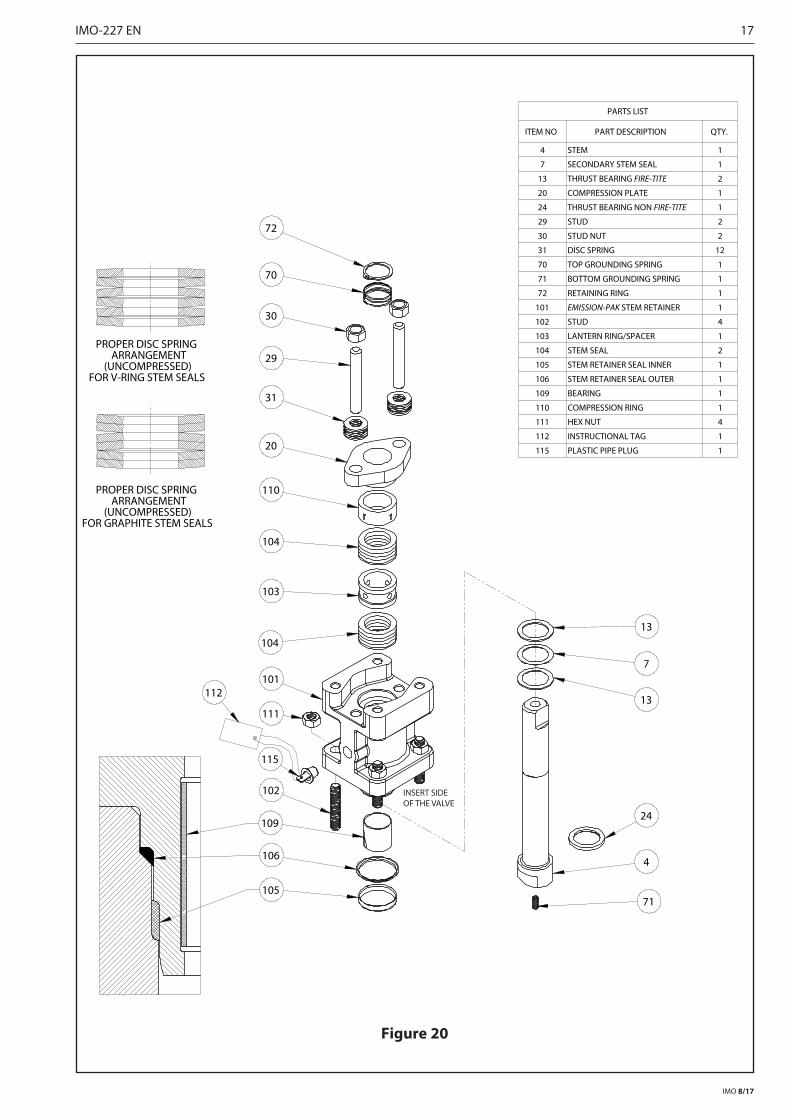
14. Remove hex nuts (111) and lift the Emission-Pak hous-ing (101) straight up until the ball end of the stem clears the valve body (1) (see Figure 6 and 20).
15. Carefully remove and discard the inner and outer stem retainer seals (105) and (106).
16. From the Emission-Pak housing (101) remove the stem (4), stem bearings (13), secondary stem seal (7), stem seals (104), bearing strip (109) and lantern ring (103), BEING CAREFUL NOT TO DAMAGE ANY SEALING SURFACE.
Figure 6
4 .6 Checking Parts
1. Clean all disassembled parts.
2. Check the stem (4) and ball (3) for damage. Pay partic-ular attention to the sealing areas.
3. Check all sealing and gasket surfaces of the body (1) and insert (2).
4. Replace any damaged parts.
5. Replace any fastener where the threads are damaged or have been heated, stretched or corroded.
6. Replace any parts that have cracks, gouges or pits that will affect sealing.
NOTE: When ordering spare parts, always include the fol-lowing information:
a. Valve catalog code from Identification plate,
b. If the valve is serialized – the serial number (stamped on the valve body or indentification plate).
c. From Figure 19 or 20, the ballooned part number, part name and quantity required.
4 .7 Assembly – Bare Stem Valves
It is advisable to replace seats and seals if complete dis-assembly and reassembly become necessary. Refer to the Repair Kit chart (see Table 9A). A lubricant, compatible with the flow media, MUST be applied to the threads on insert (2) to prevent galling during assembly.
1. Clean all valve components if not done previously.
111
OPTIONALLEAK-OFF PORT
8 IMO-227 EN
IMO 8/17
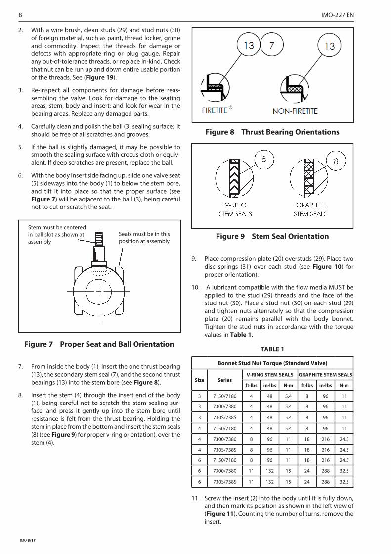
2. With a wire brush, clean studs (29) and stud nuts (30) of foreign material, such as paint, thread locker, grime and commodity. Inspect the threads for damage or defects with appropriate ring or plug gauge. Repair any out-of-tolerance threads, or replace in-kind. Check that nut can be run up and down entire usable portion of the threads. See (Figure 19).
3. Re-inspect all components for damage before reas-sembling the valve. Look for damage to the seating areas, stem, body and insert; and look for wear in the bearing areas. Replace any damaged parts.
4. Carefully clean and polish the ball (3) sealing surface: It should be free of all scratches and grooves.
5. If the ball is slightly damaged, it may be possible to smooth the sealing surface with crocus cloth or equiv-alent. If deep scratches are present, replace the ball.
6. With the body insert side facing up, slide one valve seat (5) sideways into the body (1) to below the stem bore, and tilt it into place so that the proper surface (see Figure 7) will be adjacent to the ball (3), being careful not to cut or scratch the seat.
Figure 7 Proper Seat and Ball Orientation
7. From inside the body (1), insert the one thrust bearing (13), the secondary stem seal (7), and the second thrust bearings (13) into the stem bore (see Figure 8).
8. Insert the stem (4) through the insert end of the body (1), being careful not to scratch the stem sealing sur-face; and press it gently up into the stem bore until resistance is felt from the thrust bearing. Holding the stem in place from the bottom and insert the stem seals (8) (see Figure 9) for proper v-ring orientation), over the stem (4).
Figure 8 Thrust Bearing Orientations
Figure 9 Stem Seal Orientation
9. Place compression plate (20) overstuds (29). Place two disc springs (31) over each stud (see Figure 10) for proper orientation).
10. A lubricant compatible with the flow media MUST be applied to the stud (29) threads and the face of the stud nut (30). Place a stud nut (30) on each stud (29) and tighten nuts alternately so that the compression plate (20) remains parallel with the body bonnet. Tighten the stud nuts in accordance with the torque values in Table 1.
TABLE 1
Bonnet Stud Nut Torque (Standard Valve)
Size SeriesV-RING STEM SEALS GRAPHITE STEM SEALS
ft·lbs in·lbs N·m ft·lbs in·lbs N·m
3 7150/7180 4 48 5.4 8 96 11
3 7300/7380 4 48 5.4 8 96 11
3 730S/738S 4 48 5.4 8 96 11
4 7150/7180 4 48 5.4 8 96 11
4 7300/7380 8 96 11 18 216 24.5
4 730S/738S 8 96 11 18 216 24.5
6 7150/7180 8 96 11 18 216 24.5
6 7300/7380 11 132 15 24 288 32.5
6 730S/738S 11 132 15 24 288 32.5
11. Screw the insert (2) into the body until it is fully down, and then mark its position as shown in the left view of (Figure 11). Counting the number of turns, remove the insert.
Stem must be centered in ball slot as shown atassembly
Seats must be in this position at assembly
®

IMO-227 EN 9
IMO 8/17
12. Place the valve in a vertical position, insert end up, on a clean soft surface such as a folded rag or a piece of cardboard. If the valve has grounded option, insert bottom grounding spring (71) into hole at the bottom of the stem (4). Insert the ball (3) rotating it onto the stem (4) in the closed position. If necessary, turn the stem blade to align with the ball slot. Make certain that the stem blade is in the middle of the ball slot; i.e. equal distance from the ends of the slot. Rotate the ball if necessary (see Figure 7).
Figure 10 Disc Springs Orientation
13. Place the second seat (5) into the insert (2) with the proper surface (see Figure 7) adjacent to the ball.
14. Insert the body seal (6) into the body, and gently press it into the groove.
15. Apply a lubricant compatible with the fl ow media to the threads of insert (2) and screw the insert into the body. The tightening of the insert should be done using the insert fi eld wrench. The insert must be tight-ened the same number of turns as in Step 12, insuring that the marks are no more than 1/8” (3.18 mm) apart, as shown in right view of (Figure 11).
Figure 11 Insert Installation
16. Cycle the valve slowly with a gentle back and forth motion building gradually to the full quarter turn. By cycling slowly, the seat lips will seat against the ball. Take care to avoid scratching the ball O.D.
17. Replace top grounding spring (70) and retaining ring (72) to stem (4).
4 .8 Assembly - Emission-Pak Valve
It is advisable to replace seats and all seals if complete disassembly becomes necessary. Refer to Repair Kit chart (see Table 9B). A lubricant, compatible with the fl ow media MUST be applied to the threads on insert (2) to prevent during assembly.
1. Clean all valve components if not done previously.
2. With a wire brush, clean studs (29) and stud nuts (30) of foreign material, such as paint, thread locker, grime and commodity. Inspect the threads for damage or defects with appropriate ring or plug gauge. Repair any out-of-tolerance threads, or replace in-kind. Check that nut can be run up and down entire usable portion of the threads. See (Figure 19).
3. Re-inspect all components for damage before reas-sembling the valve. Look for damage to the seating areas, stem, body and insert; and look for wear in the bearing areas. Replace any damaged parts.
4. Carefully clean and polish the ball (3) sealing surface: It should be free of all scratches and grooves.
5. If the ball is slightly damaged, it may be possible to smooth the sealing surface with crocus cloth or equiv-alent. If deep scratches are present, replace the ball.
6. With the body insert side facing up, slide one valve seat (5) sideways into the body (1) to below the stem bore, and tilt it into place so that the proper surface (see Figure 7) will be adjacent to the ball (3), being careful not to cut or scratch the seat.
7. Insert new bearing strip (109) into recess inside lower stem bore of Emission-Pak housing (101) (see Figure 20).
8. Place inner and outer stem retainer seals (105) and (106) on the Emission-Pak housing (111) shown in (Figure 20).
9. Slide one thrust bearing (13), the secondary stem seal (7) and the second thrust bearing (13) over the stem (4) (see Figure 8 for proper orientation).
10. Insert the stem subassembly into the Emission-Pak housing (101). Pull the stem outward to seat the thrust bearings. Install one set of stem seals (104) and lantern ring/spacer (103) over the stem as shown in (Figure 9). For optimal performance, pre-compress the fi rst set of stem seals.
11. Install the compression ring (111) and compression plate (20) over the stem. Using stud nut (30), apply the torque value listed in (Table 2).
12. Remove the stud nuts, compression plate, and compres-sion ring from Emission-Pak housing.

10 IMO-227 EN
IMO 8/17
13. Install the top set of stem seals (104) over the stem as shown in (Figure 9).
14. Hold the stem in place and slide the compression ring (111) and compression plate (20) over the stem (4) and studs (29).
15. Place the disc springs (31) over each stud (29) (see Figure 20 for proper orientation). A lubricant, compat-ible with the flow media, MUST be applied to the stud (29) threads and the face of the stud nut (30).
16. Place the stud nut (30) on each stud (29) and tighten nuts a few turns alternately so that the compression plate (20) remains parallel with the body bonnet. Do not fully torque down stud nuts (30) at this time.
17. Insert the Emission-Pak subassembly into the body, being careful not to damage the Emission-Pak housing seals. A lubricant, compatible with the flow media, MUST be applied to the stud (102) threads and the face of the nut (111).
18. It is recommended for optimal performance to press the Emission-Pak subassembly fully into the body so the body bonnet and the bottom flange surface of the Emission-Pak subassembly are metal to metal contact. Recommended press loads can be found in (Table 3).
19. Once metal to metal contact has been achieved, tighten the nuts (111) to the torque values in (Table 4). Apply the torque evenly in a crisscross pattern.
20. Screw the insert (2) into the body until it is fully down, and then mark its position as shown in the left view of (Figure 11). Counting the number of turns, remove the insert.
TABLE 2
Bonnet Stud Nut Torque (Emission-Pak Valve)
Size SeriesV-RING STEM SEALS GRAPHITE STEM SEALS
ft-lbs In-lbs N-m ft-lbs In-lbs N-m3 7150/7180 8 96 11 16 192 223 7300/7380 8 96 11 16 192 223 730S/738S 8 96 11 16 192 224 7150/7180 8 96 11 16 192 224 7300/7380 15 180 20 36 432 494 730S/738S 15 180 20 36 432 496 7150/7180 15 180 20 36 432 496 7300/7380 22 264 30 48 576 656 730S/738S 22 264 30 48 576 65
TABLE 3
Emission-Pak Housing Press Load
Size SeriesMinimum Load Maximum Load
tons tons3 7150/7180 8 103 7300/7380 8 103 730S/738S 8 104 7150/7180 8 104 7300/7380 10 124 730S/738S 10 126 7150/7180 10 126 7300/7380 10 126 730S/738S 10 12
TABLE 4
Emission-Pak Housing Nut TorquesLubricated Torques ft-lbs (N-m)
Fastener Size
A193 GR. B7
A193 GR. B8
A193 GR. B7M
B473 UNS N08020 QQ-N-286
Fastener Identification MarkB7 B8 B7M 35 K or 71
M8 21 – 26 (29 – 35)
20 – 25 (27 – 34)
16 – 20 (22 – 27)
12 – 15 (16 – 20)
17 – 21 (23 – 28)
M10 42 – 51 (57 – 69)
40 – 49 (54 – 67)
32 – 39 (43 – 53)
24 – 29 (32 – 39)
34 – 41 (46 – 56)
M12 73 – 89 (99 – 121)
69 – 85 (93 – 115)
56 – 68 (76 – 92)
42 – 51 (57 – 70)
59 – 72 (80 – 98)
21. Place the valve in a vertical position, insert end up, on a clean soft surface such as a folded rag or a piece of cardboard. If the valve has grounded option, insert the bottom grounding spring (71) into the hole at the bot-tom of the stem (4). Insert the ball (3) rotating it onto the stem (4) in the closed position. If necessary, turn the stem blade to align with the ball slot. Make certain that the stem blade is in the middle of the ball slot; i.e. equal distance from the ends of the slot. Rotate the ball if nec-essary (see Figure 7).
22. Place the second seat (5) into the insert (2) with the proper surface (see Figure 7) adjacent to the ball.
23. Insert the body seal (6) into the body, and gently press into the groove.
24. Apply a lubricant compatible with the flow media to the threads of insert (2) and screw the insert into the body. The tightening of the insert should be done using the insert field wrench. The insert must be tight-ened the same number of turns as in Step 20, insuring that the marks are no more than 1/8” (3.18 mm) apart, as shown in right view of (Figure 11).
25. While pulling the stem (4) outward, tighten the hex nuts (30) to the torque values in (Table 2). Apply the torque evenly, alternating between the two nuts so that the compression plate (20) remain parallel with the Emission-Pak housing bonnet.
26. Cycle the valve slowly with a gentle back and forth motion building gradually to the full quarter turn. By cycling slowly, the seat lips will seat against the ball. Take care to avoid scratching the ball O.D.
27. Replace top grounding spring (70) and retaining ring (72) to stem (4).

IMO-227 EN 11
IMO 8/17
4 .9 Testing the Valve
WARNING:
WHEN PRESSURE TESTING, EXERCISE CAUTION AND MAKE SURE ALL EQUIPMENT USED IS IN GOOD WORKING CONDITION AND APPROPRIATE FOR THE INTENDED PRESSURE.
If the valve is to be tested prior to returning to service make sure the test pressures are in accordance with an applicable standard.
When testing the valve for external tightness, keep the ball in the half open position.
If testing the valve seat tightness, please contact Metso for advice.
WARNING:
WHEN PERFORMING ANY TESTS, NEVER EXCEED THE MAXIMUM OPERATING PRESSURE OR MAXIMUM SHUT-OFF PRESSURE LISTED ON THE IDENTIFICATION PLATE!
5 HANDLE MOUNTING
1. Stroke the valve to the fully open position.
2. Lower the handle bracket (2) straight down in line with the valve stem until it is flat on the valve bonnet, and all four mounting holes align with tapped holes on the valve (see Figure 12).
NOTE: Positive stop feature on the handle bracket (2) should be forward, towards the insert.
Figure 12 Handle Assembly
3. Insert the four bracket screws (3) and lock washers (4) into the mounting holes and thread into the valve until finger tight only.
4. Aligning the slot in the handle with drive on the stem, lower handle (1) straight down in line with the valve stem until it is completely engaged. If the handle (1)
interferes with the handle bracket (2) rotate the han-dle bracket slightly to remove interference. DO NOT rotate stem!
NOTE: When looking down at the top of the valve, the cast lettering and “OPEN” arrow on the handle should be visible. If they are not visible the handle is installed upside down.
5. Install the handle screw (6) and washer (5). Tighten handle screw (6) to value listed in Table 5.
6. Confirm ball is in fully open position.
7. Rotate handle bracket (2) until the handle stop con-tacts the side of the handle (1) (see Figure 13).
Figure 13 Handle Stop
8. Tighten the four bracket screws (3) to the values listed in Table 5 .
9. Close, and then open the valve making sure the han-dle is against the handle bracket stop. Check the ball to confirm full open position. If the ball is not in the full open position with the handle against the stop, loosen the four bracket screws (3) and make any nec-essary adjustments by rotating the handle bracket. Retighten the four bracket screws (3) to the values listed in Table 5.
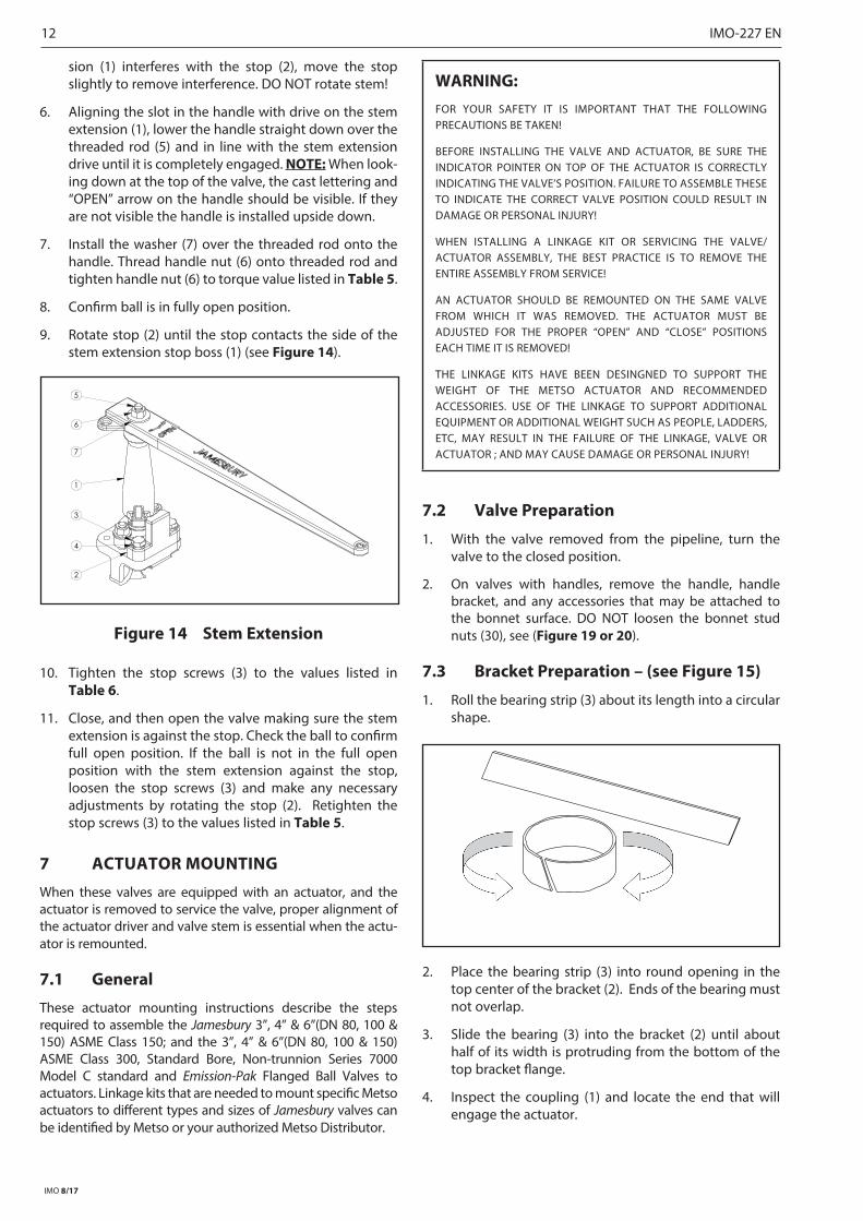
6 STEM EXTENSION MOUNTING
1. Stroke the valve to the fully open position.
2. Lower the handle stop (2) straight down in line with the valve stem until it is flat on the valve bonnet, and both mounting holes align with tapped holes on the valve (see Figure 14).
NOTE: The stop should be mounted rearward on the bonnet, between the stem and body pipeline flange. The curved side should be towards the stem.
3. Insert the stop screws (3) and lock washers (4) into the mounting holes and thread into the valve until finger tight only.
4. Screw threaded rod (5) into tapped hole on top of stem.
5. Aligning the slot in the stem extension (1) with drive on the stem, lower the stem extension straight down over the threaded rod (5) and in line with the valve stem until it is completely engaged. If the stem exten-
2
6
5
1
3 4
HANDLE AGAINSTSTOP IN OPEN
POSITION
INSERT SIDE
12 IMO-227 EN
IMO 8/17
sion (1) interferes with the stop (2), move the stop slightly to remove interference. DO NOT rotate stem!
6. Aligning the slot in the handle with drive on the stem extension (1), lower the handle straight down over the threaded rod (5) and in line with the stem extension drive until it is completely engaged. NOTE: When look-ing down at the top of the valve, the cast lettering and “OPEN” arrow on the handle should be visible. If they are not visible the handle is installed upside down.
7. Install the washer (7) over the threaded rod onto the handle. Thread handle nut (6) onto threaded rod and tighten handle nut (6) to torque value listed in Table 5.
8. Confirm ball is in fully open position.
9. Rotate stop (2) until the stop contacts the side of the stem extension stop boss (1) (see Figure 14).
Figure 14 Stem Extension
10. Tighten the stop screws (3) to the values listed in Table 6.
11. Close, and then open the valve making sure the stem extension is against the stop. Check the ball to confirm full open position. If the ball is not in the full open position with the stem extension against the stop, loosen the stop screws (3) and make any necessary adjustments by rotating the stop (2). Retighten the stop screws (3) to the values listed in Table 5.
7 ACTUATOR MOUNTING
When these valves are equipped with an actuator, and the actuator is removed to service the valve, proper alignment of the actuator driver and valve stem is essential when the actu-ator is remounted.
7 .1 General
These actuator mounting instructions describe the steps required to assemble the Jamesbury 3”, 4” & 6”(DN 80, 100 & 150) ASME Class 150; and the 3”, 4” & 6”(DN 80, 100 & 150) ASME Class 300, Standard Bore, Non-trunnion Series 7000 Model C standard and Emission-Pak Flanged Ball Valves to actuators. Linkage kits that are needed to mount specific Metso actuators to different types and sizes of Jamesbury valves can be identified by Metso or your authorized Metso Distributor.
WARNING:FOR YOUR SAFETY IT IS IMPORTANT THAT THE FOLLOWING PRECAUTIONS BE TAKEN!
BEFORE INSTALLING THE VALVE AND ACTUATOR, BE SURE THE INDICATOR POINTER ON TOP OF THE ACTUATOR IS CORRECTLY INDICATING THE VALVE’S POSITION. FAILURE TO ASSEMBLE THESE TO INDICATE THE CORRECT VALVE POSITION COULD RESULT IN DAMAGE OR PERSONAL INJURY!
WHEN ISTALLING A LINKAGE KIT OR SERVICING THE VALVE/ACTUATOR ASSEMBLY, THE BEST PRACTICE IS TO REMOVE THE ENTIRE ASSEMBLY FROM SERVICE!
AN ACTUATOR SHOULD BE REMOUNTED ON THE SAME VALVE FROM WHICH IT WAS REMOVED. THE ACTUATOR MUST BE ADJUSTED FOR THE PROPER “OPEN” AND “CLOSE” POSITIONS EACH TIME IT IS REMOVED!
THE LINKAGE KITS HAVE BEEN DESINGNED TO SUPPORT THE WEIGHT OF THE METSO ACTUATOR AND RECOMMENDED ACCESSORIES. USE OF THE LINKAGE TO SUPPORT ADDITIONAL EQUIPMENT OR ADDITIONAL WEIGHT SUCH AS PEOPLE, LADDERS, ETC, MAY RESULT IN THE FAILURE OF THE LINKAGE, VALVE OR ACTUATOR ; AND MAY CAUSE DAMAGE OR PERSONAL INJURY!
7 .2 Valve Preparation
1. With the valve removed from the pipeline, turn the valve to the closed position.
2. On valves with handles, remove the handle, handle bracket, and any accessories that may be attached to the bonnet surface. DO NOT loosen the bonnet stud nuts (30), see (Figure 19 or 20).
7 .3 Bracket Preparation – (see Figure 15)
1. Roll the bearing strip (3) about its length into a circular shape.
2. Place the bearing strip (3) into round opening in the top center of the bracket (2). Ends of the bearing must not overlap.
3. Slide the bearing (3) into the bracket (2) until about half of its width is protruding from the bottom of the top bracket flange.
4. Inspect the coupling (1) and locate the end that will engage the actuator.
1
2
5
6
7
3
4

IMO-227 EN 13
IMO 8/17
5. Insert the actuator end of the coupling (1) from the bot-tom of the bracket (2) into the protruding bearing (3).
Figure 15 Linkage Assembly – Key Drive
6. Press the coupling (1) upward until the bearing (3) sits flush on the bearing shoulder of the coupling (1) and is flush with the top flange of the bracket (2).
Figure 16 Proper bearing locations
7 .4 Bracket Attachment to Valve
1. Lower the bracket/coupling assembly on the valve, aligning the slot in the bottom of the coupling (1) with top of the valve stem.
2. Align the four bracket mounting screw holes with the tapped holes on the valve bonnet.
3. Insert the four hex head cap screws (6) and lockwashers (7) into the tapped holes. Tighten to values in Table 5.
7 .5 Actuator versus Valve Position
IMPORTANT: The actuator and valve position must agree before further assembly.
Since the valve has already been set in the closed position (Step 1 under Valve Preparation), make sure that the actua-tor is also in the closed position. EXCEPTION: lf mounting a spring-return actuator for “spring-to-open” operation; cycle the valve to the open position and proceed with the actua-tor AND valve in the open position.
7 .6 Coupling to Actuator
Key Drive Actuators (Figure 15): Install the key (4) into the key slot of the coupling (1). The key should be filed to close-ly fit into coupling and actuator keyway. If the fit is loose, apply Loctite® Keyfit or equivalent.
Male/Female Square Drive Actuators (Figure 17): No coupling prep required.
7 .7 Bracket Attachment to Actuator
1. For QPX1/M, QPX2/M, QPX4/M and QPX5/M; and Torq-Handle® A and B actuators, attach adapter plate (5) to the actuator using the four socket head cap screws (10). Tighten fasteners to values in Table 5 for steel and cast iron actuators or Table 6 for aluminum actuators
Figure 17 Linkage Assembly – Square Drive
5
3
10
2
9
8
11
6
7FEMALEMALE
14 IMO-227 EN
IMO 8/17
TABLE 5
Bolt size
Torque to Cast/Ductile Body Actuators
No lubrication
ft·lbs in·lbs N·m
1/4 8 96 11
5/16 16 192 22
3/8 27 324 37
7/16 45 540 61
1/2 67 804 91
9/16 100 1200 136
5/8 135 1620 183
3/4 225 2700 305
7/8 335 4020 454
1 520 6240 705
1-1/8 700 8400 949
1-1/4 990 11880 1342
M6 7 84 9
M8 14 168 19
M10 28 336 38
M12 48 576 65
M16 115 1380 156
M20 225 2700 305
M30 783 9396 1062
M36 1347 16164 1826
2. Place the actuator onto the valve and bracket assem-bly aligning the holes in the bracket with the holes in the actuator, and aligning the actuator drive with the coupling. Install the four hex head cap screws (8) and four lockwashers (9) through the bracket and into the actuator. Apply slightly more than finger-tightness to these fasteners, but DO NOT TIGHTEN.
3. Cycle the actuator a couple of times, allowing the assembly to position itself for proper actuator-drive to valve-drive alignment. Tighten the four hex head cap screws (8) securing the bracket to the actuator using the values in Table 5 or 6 as applicable.
WARNING:
BEWARE OF BALL MOVEMENT!
KEEP HANDS, OTHER PARTS OF THE BODY, TOOLS AND OTHER OBJECTS OUT OF THE OPEN FLOW PORT. LEAVE NO FOREIGN OBJECTS INSIDE THE VALVE. WHEN THE VALVE IS ACTUATED, THE BALL FUNCTIONS AS A CUTTING DEVICE.
7 .8 Open/Close Position Adjustment
NOTE: Refer to the appropriate Installation, Maintenance, and Operating Instructions (IMO) for specific directions on how to adjust the actuator travel stops or limit switch (see Table 7).
The actuator travel stops should be adjusted so that there is proper ball position in the full open and full close valve position. Use the following procedures to determine correct ball position.
Valve Open Position: With the valve in the open position (actuator is against the “OPEN” travel stop), The maximum allowable misalignment of the ball port in relation to the body port is 1/16 inch (1.6 mm) on either side of the ball. Do not use the seat ID to measure misalignment since, in many cases; it is larger than the ball or body port.
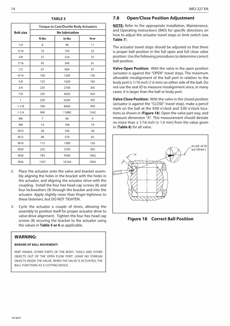
Valve Close Position: With the valve in the closed position (actuator is against the “CLOSE” travel stop), make a pencil mark on the ball at the 9:00 o’clock and 3:00 o’clock loca-tions as shown in (Figure 18). Open the valve part way, and measure dimension “A”. This measurement should deviate no more than ± 1/16 inch (± 1.6 mm) from the value given in (Table 8) for all valve.
Figure 18 Correct Ball Position
IMO-227 EN 15
IMO 8/17
Table 6
Bolt size
Torque to Cast/Ductile Body Actuators
No lubrication
ft·lbs in·lbs N·m
1/4 6 72 8
5/16 12 144 16
3/8 20 240 27
7/16 30 360 41
1/2 50 600 68
9/16 70 840 95
5/8 90 1080 122
3/4 160 1920 217
7/8 250 3000 339
1 360 4320 488
1-1/8 520 6240 705
1-1/4 700 8400 949
M6 5 60 7
M8 11 132 15
M10 22 264 30
M12 38 456 52
M16 90 1080 122
M20 170 2040 230
M30 570 6840 773
M36 950 11400 1288
Table 7
Actuator Installation, Maintenance and Operating Instructions
Actuator IMO
QPX 215
VPVL 553
B1C 6 BC 71
B1J 6 BJ 71
BCH 6 BCH 70
M 549
ADC I440, I4500 or I4600
ESR I7016
I I6500, I6600 or I6700
LCR I262
LCU I1263
Q6 I1227 or I1383
QX I3000
V I1200, I2475, I2500, I2700 or I5500
Torq-Handle 71
Contact your authorized Metso Distributor for copies of these instructions
Table 8
Dimension ”A” for Valve Closed Position AdjustmentValve Size Dimension ”A” - inch (mm)3” (DN80) 3/8 (9.53)
4” (DN 100) 1/2 (12.7)6” (DN 150) 3/4 (19.1)
8 SERVICE / SPARE PART
We recommend that valves be directed to our service cen-ters for maintenance. The service centers are equipped to provide rapid turn-around at a reasonable cost and offer new valve warranty with all reconditioned valves.
NOTE: When sending goods to the service center for repair, do not disassemble them. Clean the valve carefully and flush the valve internals. Include the material safety data-sheet(s) (MSDS) for all media flowing through the valve. Valves sent to the service center without MSDS datasheet(s) will not be accepted.
For further information on spare parts and service or assis-tance visit our web-site at www .metso .com/valves.
NOTE: When ordering spare parts, always include the fol-lowing information:
a. Valve catalog code from identification plate,
b. If the valve is serialized – the serial number (from identification plate)
c. From Figure 19 or 20, the ballooned part number, part name and quantity required.

16 IMO-227 EN
IMO 8/17
72
3
5
20
22
70
1
4
71
13
7
30
29
8
24
2
23
5
6
31
13
ITEM NO . DESCRIPTION QTY .
1 BODY 12 INSERT 13 BALL 14 STEM 15 SEAT 26 BODY SEAL 17 SECONDARY STEM SEAL* 18 STEM SEAL 1
13 STEM BEARING FIRE-TIRE 220 COMPRESSION PLATE 122 IDENTIFICATION TAG 123 POP RIVET 324 STEM BEARING NON-FIRE-TITE 129 BONNET STUD 230 BONNET STUD NUT 231 DISC SPRING 470 TOP GROUNDING SPRING 171 BOTTOM GROUNDING SPRING 172 RETAINING RING 1
*FIRE-TITE ONLY
Figure 19
IMO-227 EN 17
IMO 8/17
ITEM NO . DESCRIPTION QTY .
1 BODY 12 INSERT 13 BALL 14 STEM 15 SEAT 26 BODY SEAL 17 SECONDARY STEM SEAL* 18 STEM SEAL 1
13 STEM BEARING FIRE-TIRE 220 COMPRESSION PLATE 122 IDENTIFICATION TAG 123 POP RIVET 324 STEM BEARING NON-FIRE-TITE 129 BONNET STUD 230 BONNET STUD NUT 231 DISC SPRING 470 TOP GROUNDING SPRING 171 BOTTOM GROUNDING SPRING 172 RETAINING RING 1
70
72
7
13
24
4
105
106
102
111
101
103
104
110
20
31
29
30
13104
115
71
109
112
PROPER DISC SPRINGARRANGEMENT
(UNCOMPRESSED)FOR GRAPHITE STEM SEALS
PROPER DISC SPRINGARRANGEMENT
(UNCOMPRESSED)FOR V-RING STEM SEALS
PARTS LIST
ITEM NO PART DESCRIPTION QTY.
4 STEM 1
7 SECONDARY STEM SEAL 1
13 THRUST BEARING FIRE-TITE 2
20 COMPRESSION PLATE 1
24 THRUST BEARING NON FIRE-TITE 1
29 STUD 2
30 STUD NUT 2
31 DISC SPRING 12
70 TOP GROUNDING SPRING 1
71 BOTTOM GROUNDING SPRING 1
72 RETAINING RING 1
101 EMISSION-PAK STEM RETAINER 1
102 STUD 4
103 LANTERN RING/SPACER 1
104 STEM SEAL 2
105 STEM RETAINER SEAL INNER 1
106 STEM RETAINER SEAL OUTER 1
109 BEARING 1
110 COMPRESSION RING 1
111 HEX NUT 4
112 INSTRUCTIONAL TAG 1
115 PLASTIC PIPE PLUG 1
INSERT SIDE OF THE VALVE
Figure 20

18 IMO-227 EN
IMO 8/17
JAMESBURY 7000 SERIES FLANGED BALL VALVES
1 2 3 4 5 6 7 8 93 7150 - 31 22 36 XTZ 1 C
1 . sign VALVE SIZE ( inch / mm )INCHES 3, 4, 6
DN 80,100 150
2 . sign VALVE SERIES & STYLE7150 Standard Bore Class 1507180 Standard Bore Class 150*730S** Standard Bore Class 300 (Short)738S** Standard Bore Class 300 (Short)7300 Standard Bore Class 3007380 Standard Bore Class 300
* Metric units on nameplate.**The Special short pattern for 73_S uses class 150 face-to-face
3 . sign CONSTRUCTION / SPECIAL SERVICE– Standard (no entry)C ChlorineO OxygenV High Vacuum
VC High Vacuum CertifiedDT 125 RMS Flange FinishLA Standard Emission-Pak w/o LeakoffLL Standard Emission-Pak w/ LeakoffLC Chlorine Emission-Pak w/o LeakoffL1 Chlorine Emission-Pak w/ Leakoff
4 . sign END CONNECTION CONSTRUCTION11 Raised Face, Non-Fire-Tite, Non-Trunnion31 Raised Face, Fire-Tite, Non-Trunnion
5 . sign BODY MATERIAL*22 Carbon Steel (WCB) 28 Carbon Steel (LCC) 35 Alloy 20 (CN7M) 36 Stainless Steel (CF8M) 71 Monel (M35-1)
6 . sign BALL AND STEM MATERIAL SIZE RANGE35 Alloy 20 All36 316 Stainless Steel All71 Monel All73 Hastelloy AllHB 316 SS, 17-4 PH
00 Same as body All (Carbon steel not available)
7 . sign SEAT MATERIAL SIZE RANGEXTZ Xtreme®/PTFE/PTFE AllTTT PTFE/PTFE/PTFE AllBTT PFA/PTFE/PTFE All
LGG † 1 2 PEEK/GRAPHITE/GRAPHITE AllUUU 1 UHMW/UHMW/UHMW AllMBT 1 2 Barrier-filled PTFE 2” - 4” (DN 50 - 100)
† Requires 17-4PH StemNote 1: Non-Fire-Tite onlyNote 2: Not a self relieving seat design
8 . sign BOLTS NUTS1 ASTM A193 Gr B7 ASTM A194 Gr 2H
2ASTM A193 Gr B8, B8C, B8M or B8T
(Class 2)
ASTM A194 Gr 8A, 8CA, 8MA, 8TA, or 8FA
4 QQ-N-286
5 ASTM A193 Gr B7M ASTM A194 Gr 2HM
9 . sign MODELC All Sizes
For options not defined, contact factory.

IMO-227 EN 19
IMO 8/17
TABLE 9A - Repair Kit Selector (Standard Valve)
Selecting the right Repair kit is as easy as A-B. Find the valve catalog code from thenameplate (see Figure 1). Using the information below build the Repair kit number.
Size & Style Seats
A BRKN-392 - XTZ
eg. 3” 7150 31 22HB XTZ 1 CA Size & Style
RKN-392 - 3 7150 RKN-393 - 4 7150 RKN-395 - 6 7150RKN-392 - 3 7300 RKN-394 - 4 7300 RKN-396 - 6 7300RKN-392 - 3 730S RKN-394 - 4 730S RKN-396 - 6 730S
B Seats
XTZ - Xtreme seats LGG - PEEK seats ZTT - TFM seatsTTT - PTFE seats UUU - UHWMPE seatsBTT - PFA seats MBT - Barrier seats
WARNING: If the valve you are selecting a Repair Kit for has a “Special Service” tag, check with your authorized Metso Distributor for help in selecting the correct kit.

Metso Flow Control Inc.
Europe, Vanha Porvoontie 229, P.O. Box 304, FI-01301 Vantaa, Finland. Tel. +358 20 483 150. Fax +358 20 483 151North America, 44 Bowditch Drive, P.O. Box 8044, Shrewsbury, M A 01545, USA. Tel. +1 508 852 0200. Fax +1 508 852 8172
South America, Av. Independéncia, 2500-Iporanga, 18087-101, Sorocaba-São Paulo, Brazil. Tel. +55 15 2102 9700. Fax +55 15 2102 9748 Asia Paci�c, 238B Thomson Road, #17-01 Novena Square Tower B, Singapore 307685. Tel. +65 6511 1011. Fax +65 6250 0830
China, 11/F, China Youth Plaza, No.19 North Rd of East 3rd Ring Rd, Chaoyang District, Beijing 100020, China. Tel. +86 10 6566 6600. Fax +86 10 6566 2583Middle East, Roundabout 8, Unit AB-07, P.O. Box 17175, Jebel Ali Freezone, Dubai, United Arab Emirates. Tel. +971 4 883 6974. Fax +971 4 883 6836
www.metso.com/valves
Subject to change without prior notice.
20 IMO-227 EN
TABLE 9B - Repair Kit Selector (Emission-Pak Valve)
Selecting the right Repair kit is as easy as A-B. Find the valve catalog code from thenameplate (see Figure 1). Using the information below build the Repair kit number.
Size & Style Seats
A BRKN-419 - XTZ
eg. 3” 7150 LL 31 22HB XTZ 1 CA Size & Style
RKN-419 - 3 7150 RKN-420 - 4 7150 RKN-422 - 6 7150RKN-419 - 3 7300 RKN-421 - 4 7300 RKN-423 - 6 7300RKN-419 - 3 730S RKN-421 - 4 730S RKN-423 - 6 730S
B Seats
XTZ - Xtreme seats LGG - PEEK seats ZTT - TFM seatsTTT - PTFE seats UUU - UHWMPE seatsBTT - PFA seats MBT - Barrier seats
WARNING: If the valve you are selecting a Repair Kit for has a “Special Service” tag, check with your authorized Metso Distributor for help in selecting the correct kit.