flaring with r410a flare tools) to achieve the specified ... · pdf fileinstallation...
TRANSCRIPT
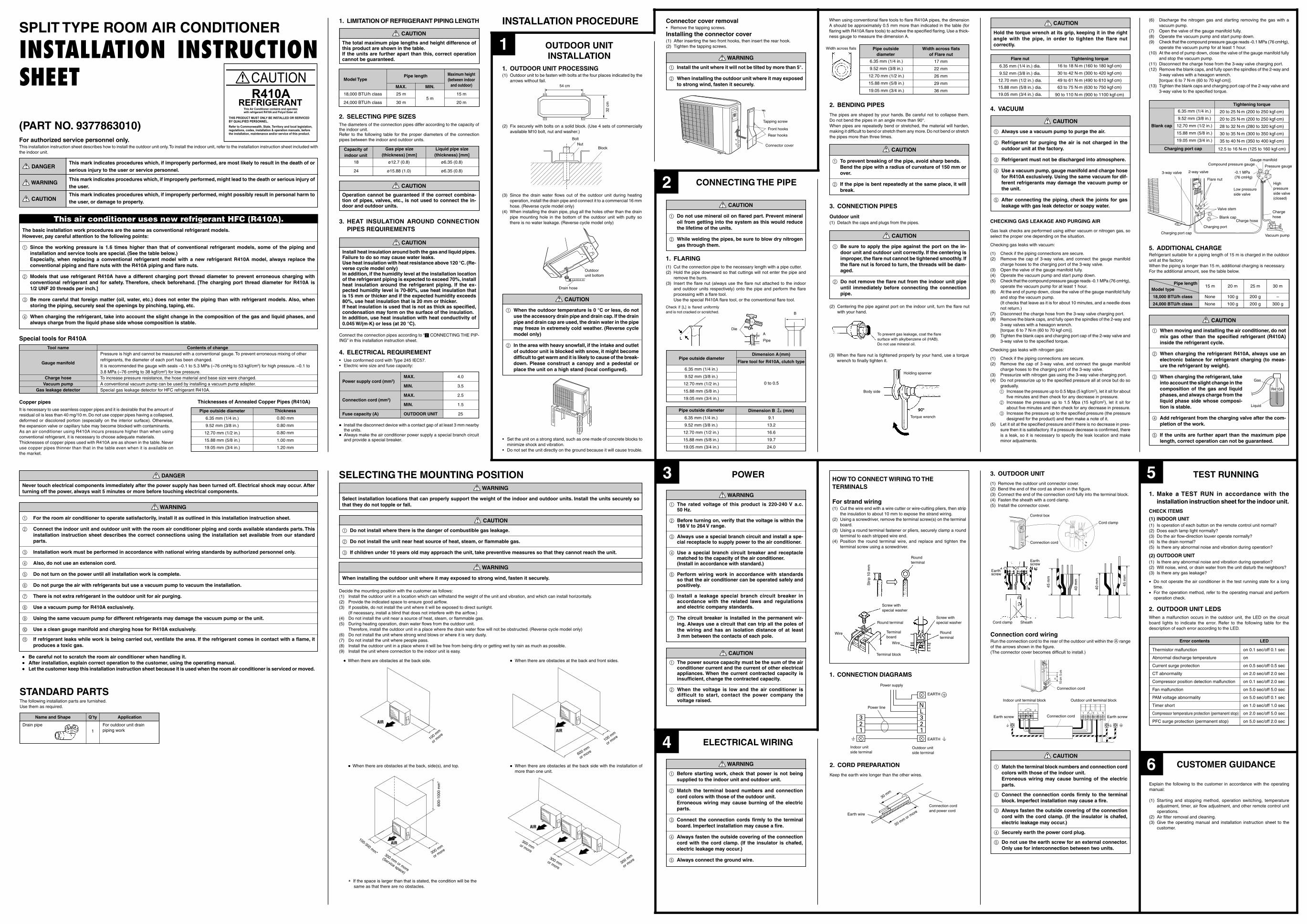
SPLIT TYPE ROOM AIR CONDITIONER
INSTALLATION INSTRUCTIONSHEET
(PART NO. 9377863010)For authorized service personnel only.This installation instruction sheet describes how to install the outdoor unit only. To install the indoor unit, refer to the installation instruction sheet included withthe indoor unit.
DANGERThis mark indicates procedures which, if improperly performed, are most likely to result in the death of orserious injury to the user or service personnel.
WARNINGThis mark indicates procedures which, if improperly performed, might lead to the death or serious injury ofthe user.
CAUTIONThis mark indicates procedures which, if improperly performed, might possibly result in personal harm tothe user, or damage to property.
This air conditioner uses new refrigerant HFC (R410A).The basic installation work procedures are the same as conventional refrigerant models.However, pay careful attention to the following points:
1 Since the working pressure is 1.6 times higher than that of conventional refrigerant models, some of the piping andinstallation and service tools are special. (See the table below.)Especially, when replacing a conventional refrigerant model with a new refrigerant R410A model, always replace theconventional piping and flare nuts with the R410A piping and flare nuts.
2 Models that use refrigerant R410A have a different charging port thread diameter to prevent erroneous charging withconventional refrigerant and for safety. Therefore, check beforehand. [The charging port thread diameter for R410A is1/2 UNF 20 threads per inch.]
3 Be more careful that foreign matter (oil, water, etc.) does not enter the piping than with refrigerant models. Also, whenstoring the piping, securely seal the openings by pinching, taping, etc.
4 When charging the refrigerant, take into account the slight change in the composition of the gas and liquid phases, andalways charge from the liquid phase side whose composition is stable.
Special tools for R410AContents of change
Pressure is high and cannot be measured with a conventional gauge. To prevent erroneous mixing of otherrefrigerants, the diameter of each port has been changed.It is recommended the gauge with seals –0.1 to 5.3 MPa (–76 cmHg to 53 kgf/cm2) for high pressure. –0.1 to3.8 MPa (–76 cmHg to 38 kgf/cm2) for low pressure.To increase pressure resistance, the hose material and base size were changed.A conventional vacuum pump can be used by installing a vacuum pump adapter.Special gas leakage detector for HFC refrigerant R410A.
Tool name
Gauge manifold
Charge hoseVacuum pump
Gas leakage detector
Copper pipesIt is necessary to use seamless copper pipes and it is desirable that the amount ofresidual oil is less than 40 mg/10 m. Do not use copper pipes having a collapsed,deformed or discolored portion (especially on the interior surface). Otherwise,the expansion valve or capillary tube may become blocked with contaminants.As an air conditioner using R410A incurs pressure higher than when usingconventional refrigerant, it is necessary to choose adequate materials.Thicknesses of copper pipes used with R410A are as shown in the table. Neveruse copper pipes thinner than that in the table even when it is available onthe market.
Pipe outside diameter
6.35 mm (1/4 in.)
9.52 mm (3/8 in.)
12.70 mm (1/2 in.)
15.88 mm (5/8 in.)
19.05 mm (3/4 in.)
Thickness
0.80 mm
0.80 mm
0.80 mm
1.00 mm
1.20 mm
Thicknesses of Annealed Copper Pipes (R410A)
STANDARD PARTSThe following installation parts are furnished.Use them as required.
SELECTING THE MOUNTING POSITION WARNING
Select installation locations that can properly support the weight of the indoor and outdoor units. Install the units securely sothat they do not topple or fall.
CAUTION
1 Do not install where there is the danger of combustible gas leakage.
2 Do not install the unit near heat source of heat, steam, or flammable gas.
3 If children under 10 years old may approach the unit, take preventive measures so that they cannot reach the unit.
WARNING
When installing the outdoor unit where it may exposed to strong wind, fasten it securely.
Decide the mounting position with the customer as follows:(1) Install the outdoor unit in a location which can withstand the weight of the unit and vibration, and which can install horizontally.(2) Provide the indicated space to ensure good airflow.(3) If possible, do not install the unit where it will be exposed to direct sunlight.
(If necessary, install a blind that does not interfere with the airflow.)(4) Do not install the unit near a source of heat, steam, or flammable gas.(5) During heating operation, drain water flows from the outdoor unit.
Therefore, install the outdoor unit in a place where the drain water flow will not be obstructed. (Reverse cycle model only)(6) Do not install the unit where strong wind blows or where it is very dusty.(7) Do not install the unit where people pass.(8) Install the outdoor unit in a place where it will be free from being dirty or getting wet by rain as much as possible.(9) Install the unit where connection to the indoor unit is easy.
••••• When there are obstacles at the back side. ••••• When there are obstacles at the back and front sides.
••••• When there are obstacles at the back side with the installation ofmore than one unit.
AIR
100 mm
or more100 m
m
or more
300 mmor more
300 mmor more300 m
m
or more
100-300 mm* 300 mm or more
(Service space)
300 mm
or more
600-
1000
mm
*
••••• When there are obstacles at the back, side(s), and top.
600 mm
or more
* If the space is larger than that is stated, the condition will be thesame as that there are no obstacles.
1. LIMITATION OF REFRIGERANT PIPING LENGTH
CAUTION
The total maximum pipe lengths and height difference ofthis product are shown in the table.If the units are further apart than this, correct operationcannot be guaranteed.
2. SELECTING PIPE SIZESThe diameters of the connection pipes differ according to the capacity ofthe indoor unit.Refer to the following table for the proper diameters of the connectionpipes between the indoor and outdoor units.
3. HEAT INSULATION AROUND CONNECTIONPIPES REQUIREMENTS
CAUTION
Install heat insulation around both the gas and liquid pipes.Failure to do so may cause water leaks.Use heat insulation with heat resistance above 120 °C. (Re-verse cycle model only)In addition, if the humidity level at the installation locationof the refrigerant piping is expected to exceed 70%, installheat insulation around the refrigerant piping. If the ex-pected humidity level is 70-80%, use heat insulation thatis 15 mm or thicker and if the expected humidity exceeds80%, use heat insulation that is 20 mm or thicker.If heat insulation is used that is not as thick as specified,condensation may form on the surface of the insulation.In addition, use heat insulation with heat conductivity of0.045 W/(m·K) or less (at 20 °C).
Connect the connection pipes according to “2 CONNECTING THE PIP-ING” in this installation instruction sheet.
4. ELECTRICAL REQUIREMENT• Use conformed cord with Type 245 IEC57.• Electric wire size and fuse capacity:
18 ø12.7 (0.8) ø6.35 (0.8)
24 ø15.88 (1.0) ø6.35 (0.8)
Liquid pipe size(thickness) [mm]
Capacity ofindoor unit
Gas pipe size(thickness) [mm]
CAUTION
Operation cannot be guaranteed if the correct combina-tion of pipes, valves, etc., is not used to connect the in-door and outdoor units.
••••• Install the disconnect device with a contact gap of at least 3 mm nearbythe units.
••••• Always make the air conditioner power supply a special branch circuitand provide a special breaker.
Power supply cord (mm2)MAX. 4.0
MIN. 3.5
Connection cord (mm2)MAX. 2.5
MIN. 1.5
Fuse capacity (A) OUTDOOR UNIT 25
1
INSTALLATION PROCEDURE
OUTDOOR UNITINSTALLATION
1. OUTDOOR UNIT PROCESSING(1) Outdoor unit to be fasten with bolts at the four places indicated by the
arrows without fail.
(2) Fix securely with bolts on a solid block. (Use 4 sets of commerciallyavailable M10 bolt, nut and washer.)
BoltNut
Block
2 CONNECTING THE PIPE
2. BENDING PIPES
The pipes are shaped by your hands. Be careful not to collapse them.Do not bend the pipes in an angle more than 90°.When pipes are repeatedly bend or stretched, the material will harden,making it difficult to bend or stretch them any more. Do not bend or stretchthe pipes more than three times.
CAUTION
1 Do not use mineral oil on flared part. Prevent mineraloil from getting into the system as this would reducethe lifetime of the units.
2 While welding the pipes, be sure to blow dry nitrogengas through them.
1. FLARING(1) Cut the connection pipe to the necessary length with a pipe cutter.(2) Hold the pipe downward so that cuttings will not enter the pipe and
remove the burrs.(3) Insert the flare nut (always use the flare nut attached to the indoor
and outdoor units respectively) onto the pipe and perform the flareprocessing with a flare tool.Use the special R410A flare tool, or the conventional flare tool.
When using conventional flare tools to flare R410A pipes, the dimensionA should be approximately 0.5 mm more than indicated in the table (forflaring with R410A flare tools) to achieve the specified flaring. Use a thick-ness gauge to measure the dimension A.
Pipe outsidediameter
Width across flatsof Flare nut
Width across flats
Check if [L] is flared uniformlyand is not cracked or scratched. B
DieA
Pipe
3. CONNECTION PIPES
Outdoor unit(1) Detach the caps and plugs from the pipes.
CAUTION
1 Be sure to apply the pipe against the port on the in-door unit and outdoor unit correctly. If the centering isimproper, the flare nut cannot be tightened smoothly. Ifthe flare nut is forced to turn, the threads will be dam-aged.
2 Do not remove the flare nut from the indoor unit pipeuntil immediately before connecting the connectionpipe.
(2) Centering the pipe against port on the indoor unit, turn the flare nutwith your hand.
To prevent gas leakage, coat the flaresurface with alkylbenzene oil (HAB).Do not use mineral oil.
(3) When the flare nut is tightened properly by your hand, use a torquewrench to finally tighten it.
CAUTION
Hold the torque wrench at its grip, keeping it in the rightangle with the pipe, in order to tighten the flare nutcorrectly.
Flare nut Tightening torque
6.35 mm (1/4 in.) dia.
9.52 mm (3/8 in.) dia.
12.70 mm (1/2 in.) dia.
15.88 mm (5/8 in.) dia.
19.05 mm (3/4 in.) dia.
6.35 mm (1/4 in.)
9.52 mm (3/8 in.)
12.70 mm (1/2 in.)
15.88 mm (5/8 in.)
19.05 mm (3/4 in.)
0 to 0.5
Pipe outside diameterDimension A (mm)
Flare tool for R410A, clutch type
6.35 mm (1/4 in.)
9.52 mm (3/8 in.)
12.70 mm (1/2 in.)
15.88 mm (5/8 in.)
19.05 mm (3/4 in.)
9.1
13.2
16.6
19.7
24.0
Pipe outside diameter Dimension B (mm)0 -0.4
6.35 mm (1/4 in.)
9.52 mm (3/8 in.)
12.70 mm (1/2 in.)
15.88 mm (5/8 in.)
19.05 mm (3/4 in.)
17 mm
22 mm
26 mm
29 mm
36 mm
16 to 18 N·m (160 to 180 kgf·cm)
30 to 42 N·m (300 to 420 kgf·cm)
49 to 61 N·m (490 to 610 kgf·cm)
63 to 75 N·m (630 to 750 kgf·cm)
90 to 110 N·m (900 to 1100 kgf·cm)
DANGER
Never touch electrical components immediately after the power supply has been turned off. Electrical shock may occur. Afterturning off the power, always wait 5 minutes or more before touching electrical components.
WARNING
1 For the room air conditioner to operate satisfactorily, install it as outlined in this installation instruction sheet.
2 Connect the indoor unit and outdoor unit with the room air conditioner piping and cords available standards parts. Thisinstallation instruction sheet describes the correct connections using the installation set available from our standardparts.
3 Installation work must be performed in accordance with national wiring standards by authorized personnel only.
4 Also, do not use an extension cord.
5 Do not turn on the power until all installation work is complete.
6 Do not purge the air with refrigerants but use a vacuum pump to vacuum the installation.
7 There is not extra refrigerant in the outdoor unit for air purging.
8 Use a vacuum pump for R410A exclusively.
9 Using the same vacuum pump for different refrigerants may damage the vacuum pump or the unit.
0 Use a clean gauge manifold and charging hose for R410A exclusively.
A If refrigerant leaks while work is being carried out, ventilate the area. If the refrigerant comes in contact with a flame, itproduces a toxic gas.
••••• Be careful not to scratch the room air conditioner when handling it.••••• After installation, explain correct operation to the customer, using the operating manual.••••• Let the customer keep this installation instruction sheet because it is used when the room air conditioner is serviced or moved.
Name and Shape Q’ty Application
For outdoor unit drainpiping work1
Drain pipe
MAX.
25 m
30 m
Pipe length
MIN.
5 m15 m
20 m
Maximum height(between indoor
and outdoor)Model Type
18,000 BTU/h class
24,000 BTU/h class
(3) Since the drain water flows out of the outdoor unit during heatingoperation, install the drain pipe and connect it to a commercial 16 mmhose. (Reverse cycle model only)
(4) When installing the drain pipe, plug all the holes other than the drainpipe mounting hole in the bottom of the outdoor unit with putty sothere is no water leakage. (Reverse cycle model only)
Tapping screw
Rear hooks
Connector cover
Front hooks
Connector cover removal• Remove the tapping screws.
Installing the connector cover(1) After inserting the two front hooks, then insert the rear hook.(2) Tighten the tapping screws.
WARNING
1 Install the unit where it will not be tilted by more than 5°.
2 When installing the outdoor unit where it may exposedto strong wind, fasten it securely.
4. VACUUMTightening torque
20 to 25 N·m (200 to 250 kgf·cm)
20 to 25 N·m (200 to 250 kgf·cm)
28 to 32 N·m (280 to 320 kgf·cm)
30 to 35 N·m (300 to 350 kgf·cm)
35 to 40 N·m (350 to 400 kgf·cm)
12.5 to 16 N·m (125 to 160 kgf·cm)
Blank cap
6.35 mm (1/4 in.)
9.52 mm (3/8 in.)
12.70 mm (1/2 in.)
15.88 mm (5/8 in.)
19.05 mm (3/4 in.)
Charging port cap
LOHI
Flare nut
3-way valve -0.1 MPa(76 cmHg)
Highpressureside valve(closed)
Low pressureside valve
Blank capChargehose
Vacuum pump
2-way valve
Valve stem
Charge hose
Charging port cap
Charging port
Gauge manifoldCompound pressure gauge Pressure gauge
5. ADDITIONAL CHARGERefrigerant suitable for a piping length of 15 m is charged in the outdoorunit at the factory.When the piping is longer than 15 m, additional charging is necessary.For the additional amount, see the table below.
Gas
Liquid
CAUTION
1 When moving and installing the air conditioner, do notmix gas other than the specified refrigerant (R410A)inside the refrigerant cycle.
2 When charging the refrigerant R410A, always use anelectronic balance for refrigerant charging (to meas-ure the refrigerant by weight).
3 When charging the refrigerant, takeinto account the slight change in thecomposition of the gas and liquidphases, and always charge from theliquid phase side whose composi-tion is stable.
4 Add refrigerant from the charging valve after the com-pletion of the work.
5 If the units are further apart than the maximum pipelength, correct operation can not be guaranteed.
R410A
3 POWER
WARNING
1 The rated voltage of this product is 220-240 V a.c.50 Hz.
2 Before turning on, verify that the voltage is within the198 V to 264 V range.
3 Always use a special branch circuit and install a spe-cial receptacle to supply power to the air conditioner.
4 Use a special branch circuit breaker and receptaclematched to the capacity of the air conditioner.(Install in accordance with standard.)
5 Perform wiring work in accordance with standardsso that the air conditioner can be operated safely andpositively.
6 Install a leakage special branch circuit breaker inaccordance with the related laws and regulationsand electric company standards.
7 The circuit breaker is installed in the permanent wir-ing. Always use a circuit that can trip all the poles ofthe wiring and has an isolation distance of at least3 mm between the contacts of each pole.
CAUTION
1 The power source capacity must be the sum of the airconditioner current and the current of other electricalappliances. When the current contracted capacity isinsufficient, change the contracted capacity.
2 When the voltage is low and the air conditioner isdifficult to start, contact the power company thevoltage raised.
Pipe lengthModel type
18,000 BTU/h class
24,000 BTU/h class
15 m 20 m 25 m 30 m
None
None
100 g
100 g
200 g
200 g
–
300 g
54 cm
32 c
m
Drain hose
Outdoorunit bottom
CAUTION
1 When the outdoor temperature is 0 °C or less, do notuse the accessory drain pipe and drain cap. If the drainpipe and drain cap are used, the drain water in the pipemay freeze in extremely cold weather. (Reverse cyclemodel only)
2 In the area with heavy snowfall, if the intake and outletof outdoor unit is blocked with snow, it might becomedifficult to get warm and it is likely to cause of the break-down. Please construct a canopy and a pedestal orplace the unit on a high stand (local configured).
WARNING
1 Before starting work, check that power is not beingsupplied to the indoor unit and outdoor unit.
2 Match the terminal board numbers and connectioncord colors with those of the outdoor unit.Erroneous wiring may cause burning of the electricparts.
3 Connect the connection cords firmly to the terminalboard. Imperfect installation may cause a fire.
4 Always fasten the outside covering of the connectioncord with the cord clamp. (If the insulator is chafed,electric leakage may occur.)
5 Always connect the ground wire.
4 ELECTRICAL WIRING
HOW TO CONNECT WIRING TO THETERMINALS
For strand wiring(1) Cut the wire end with a wire cutter or wire-cutting pliers, then strip
the insulation to about 10 mm to expose the strand wiring.(2) Using a screwdriver, remove the terminal screw(s) on the terminal
board.(3) Using a round terminal fastener or pliers, securely clamp a round
terminal to each stripped wire end.(4) Position the round terminal wire, and replace and tighten the
terminal screw using a screwdriver.
Str
ip 1
0 m
m
Roundterminal
Wire
Screw withspecial washer
Round terminal
Terminalboard
Wire
Screw withspecial washer
Roundterminal
Terminal block
1. CONNECTION DIAGRAMS
3. OUTDOOR UNIT
(1) Remove the outdoor unit connector cover.(2) Bend the end of the cord as shown in the figure.(3) Connect the end of the connection cord fully into the terminal block.(4) Fasten the sheath with a cord clamp.(5) Install the connector cover.
2. CORD PREPARATION
Keep the earth wire longer than the other wires.
Connection cordand power cord
30 mm
50 mm or m
oreEarth wire
Power supply
Outdoor unitside terminal
Indoor unitside terminal
Power line
EARTH
NL3
1
32 21
EARTH
1 2 3 L N1 2 3 4
45 m
m
Outdoor unit terminal blockIndoor unit terminal block
Connection cordEarth screw Earth screw
Connection cord
Connection cord
Control box
40 m
m
40 m
m
45 m
m
SheathCord clamp
Earthscrew
Cord clamp
Earthscrew
10 c
m5
cm
Connection cord wiringRun the connection cord to the rear of the outdoor unit within the A rangeof the arrows shown in the figure.(The connector cover becomes difficult to install.)
CAUTION
1 Match the terminal block numbers and connection cordcolors with those of the indoor unit.Erroneous wiring may cause burning of the electricparts.
2 Connect the connection cords firmly to the terminalblock. Imperfect installation may cause a fire.
3 Always fasten the outside covering of the connectioncord with the cord clamp. (If the insulator is chafed,electric leakage may occur.)
4 Securely earth the power cord plug.
5 Do not use the earth screw for an external connector.Only use for interconnection between two units.
5 TEST RUNNING
1. Make a TEST RUN in accordance with theinstallation instruction sheet for the indoor unit.
CHECK ITEMS
(1) INDOOR UNIT(1) Is operation of each button on the remote control unit normal?(2) Does each lamp light normally?(3) Do the air flow-direction louver operate normally?(4) Is the drain normal?(5) Is there any abnormal noise and vibration during operation?
(2) OUTDOOR UNIT(1) Is there any abnormal noise and vibration during operation?(2) Will noise, wind, or drain water from the unit disturb the neighbors?(3) Is there any gas leakage?
• Do not operate the air conditioner in the test running state for a longtime.
• For the operation method, refer to the operating manual and performoperation check.
2. OUTDOOR UNIT LEDSWhen a malfunction occurs in the outdoor unit, the LED on the circuitboard lights to indicate the error. Refer to the following table for thedescription of each error according to the LED.
Error contents
Thermistor malfunction
Abnormal discharge temperature
Current surge protection
CT abnormality
Compressor position detection malfunction
Fan malfunction
PAM voltage abnormality
Timer short
Compressor temperature protection (permanent stop)
PFC surge protection (permanent stop)
LED
on 0.1 sec/off 0.1 sec
on
on 0.5 sec/off 0.5 sec
on 2.0 sec/off 2.0 sec
on 0.1 sec/off 2.0 sec
on 5.0 sec/off 5.0 sec
on 5.0 sec/off 0.1 sec
on 1.0 sec/off 1.0 sec
on 2.0 sec/off 5.0 sec
on 5.0 sec/off 2.0 sec
6 CUSTOMER GUIDANCE
Explain the following to the customer in accordance with the operatingmanual:
(1) Starting and stopping method, operation switching, temperatureadjustment, timer, air flow adjustment, and other remote control unitoperations.
(2) Air filter removal and cleaning.(3) Give the operating manual and installation instruction sheet to the
customer.
CAUTION
1 Always use a vacuum pump to purge the air.
2 Refrigerant for purging the air is not charged in theoutdoor unit at the factory.
3 Refrigerant must not be discharged into atmosphere.
4 Use a vacuum pump, gauge manifold and charge hosefor R410A exclusively. Using the same vacuum for dif-ferent refrigerants may damage the vacuum pump orthe unit.
5 After connecting the piping, check the joints for gasleakage with gas leak detector or soapy water.
CAUTION
1 To prevent breaking of the pipe, avoid sharp bends.Bend the pipe with a radius of curvature of 150 mm orover.
2 If the pipe is bent repeatedly at the same place, it willbreak.
CHECKING GAS LEAKAGE AND PURGING AIR
Gas leak checks are performed using either vacuum or nitrogen gas, soselect the proper one depending on the situation.
Checking gas leaks with vacuum:
(1) Check if the piping connections are secure.(2) Remove the cap of 3-way valve, and connect the gauge manifold
charge hoses to the charging port of the 3-way valve.(3) Open the valve of the gauge manifold fully.(4) Operate the vacuum pump and start pump down.(5) Check that the compound pressure gauge reads -0.1 MPa (76 cmHg),
operate the vacuum pump for at least 1 hour.(6) At the end of pump down, close the valve of the gauge manifold fully
and stop the vacuum pump.(It checks that leave as it is for about 10 minutes, and a needle doesnot return.)
(7) Disconnect the charge hose from the 3-way valve charging port.(8) Remove the blank caps, and fully open the spindles of the 2-way and
3-way valves with a hexagon wrench.[torque: 6 to 7 N.m (60 to 70 kgf.cm)].
(9) Tighten the blank caps and charging port cap of the 2-way valve and3-way valve to the specified torque.
Checking gas leaks with nitrogen gas:
(1) Check if the piping connections are secure.(2) Remove the cap of 3-way valve, and connect the gauge manifold
charge hoses to the charging port of the 3-way valve.(3) Pressurize with nitrogen gas using the 3-way valve charging port.(4) Do not pressurize up to the specified pressure all at once but do so
gradually.1 Increase the pressure up to 0.5 Mpa (5 kgf/cm2), let it sit for about
five minutes and then check for any decrease in pressure.2 Increase the pressure up to 1.5 Mpa (15 kgf/cm2), let it sit for
about five minutes and then check for any decrease in pressure.3 Increase the pressure up to the specified pressure (the pressure
designed for the product) and then make a note of it.(5) Let it sit at the specified pressure and if there is no decrease in pres-
sure then it is satisfactory. If a pressure decrease is confirmed, thereis a leak, so it is necessary to specify the leak location and makeminor adjustments.
(6) Discharge the nitrogen gas and starting removing the gas with avacuum pump.
(7) Open the valve of the gauge manifold fully.(8) Operate the vacuum pump and start pump down.(9) Check that the compound pressure gauge reads -0.1 MPa (76 cmHg),
operate the vacuum pump for at least 1 hour.(10) At the end of pump down, close the valve of the gauge manifold fully
and stop the vacuum pump.(11) Disconnect the charge hose from the 3-way valve charging port.(12) Remove the blank caps, and fully open the spindles of the 2-way and
3-way valves with a hexagon wrench.[torque: 6 to 7 N.m (60 to 70 kgf.cm)].
(13) Tighten the blank caps and charging port cap of the 2-way valve and3-way valve to the specified torque.
• Set the unit on a strong stand, such as one made of concrete blocks tominimize shock and vibration.
• Do not set the unit directly on the ground because it will cause trouble.
Torque wrench
Holding spanner
Body side
9377863010_IM.p65 28/7/06, 15:261