flat panel edit
DESCRIPTION
noTRANSCRIPT

PROPERTY OF PREPARED BY DATE--
01
Array’s 2905
APPROVED BY DATE
DR KHAIRUL 12 FEB 2015PAGE 01 OF 20
1.0 SCOPEThis document presides over the use of Array’s 2905 laser film digitization.Hardware and software criterion are clearly defined and specified in order to standardize and maintain good quality control of digitized radiographic image.This document only covers on the process procedure to digitize conventional radiograph films.Hence, this document does not include any guidance or specifications with regard to the evaluation of the digitized images for acceptance or rejection to any criteria pertaining to flaw sizing, defect recognition or any other structural integrity evaluation of the subject or part imaged.NOTE: Other systems that exhibit equivalent capabilities enlisted in this document may be used upon consent from a Malaysia Nuclear Agency personnel who is qualified, and certified in the film digitization process.
2.0 PROCEDURE GUIDELINES FORTHE DIGITIZATION OF RADIOGRAPHSThis procedure provides guidelines to fully perform digitization radiograph process in accordance to industrial standard.
3.0 PURPOSEThe aim of this procedure is to clarify the essential items required for preparing, handling, digitizing and storing industrial radiographs. This procedure shall also define quality control standards that will allow for uniformity of data integrity and image quality. This is done in an effort to allow for the digitization of existing radiographs for subsequent interpretation and long term storage.
4.0 REFERENCED DOCUMENTS4.1. Applicable Codes
4.1.1. ASME Section V, Article 2, Mandatory Appendix III: Digital Image Acquisition, Display, and Storage for Radiography and Radioscopy, 2010 Edition
4.1.2 ASME Section V, Article 2, Mandatory Appendix VI and Supplement A: Digital Image Acquisition, Display, Interpretation, and Storage of Radiographs for Nuclear Applications, 2010 Edition, as applicable.
4.1.3 EN 14096-1, Non-destructive testing — Qualification of radiographic film digitization systems — Part 1: Definitions, quantitative measurements of image quality parameters, standard reference film and qualitative control.
4.2 Malaysia Nuclear Agency Level III who is qualified, and certified in the film digitization process shall determine Array’s 2905 Start Systems User's Manual.
4.3 Array 2905 Start Systems User's Manual or equivalent as determined by a Array’s 2905 Instruction Manual (for model Array’s 2905 film digitized) or equivalent as determined by a Malaysia Nuclear Agency Level III who is qualified, and certified in the film digitization process.

PRO PERTY OF PREPARED BY DATE-
01
Array’s 2905
APPROVED BY DATE
DR KHAIRUL- 12 FEB 2015PAGE 02 OF 20
5.0 PERSONNEL REQUIREMENTS5.
5.1. Digitization Technician5.1.1. Digitization personnel are not required to hold any NDT certificate but are not
required to demonstrate.5.1.2. Furthermore, digitization analysts are required to undergo a minimum of 2
hours of training in the use of the software operating system, the digitization software, the digital storage device and the film scanning hardware. Testing shall validate level of understanding.
6.0 SAFETY REQUIREMENTS6.1 All equipment shall follow the manufacturer`s guidelines and instruction manuals for
safety considerations.6.2 All personnel actions shall comply with company safety regulations.
7.0EQUIPMENT AND SUPPLIES7.1 Film Digitizer
7.1.1 Malaysia Nuclear Agency Level III who is qualified and certified in the film digitization process shall determine whether or not Array’s 2905 Film Digitizer or equivalent could be used.
7.1.2Array’s 2095 Packing
Dimensions W960 x D730 x H645
Weight Approx. 104kg
Environment conditions
-20 -600C
10-90% Rh (non-condensing)

PROPERTY OF PREPARED BY DATE -
01
Array’s 2905
APPROVED BY DATE
DR KHAIRUL- 12 FEB 2015PAGE 03 OF 20
7.1. Array’s 2095 Main Specifications:
Scan Size Max 365mmSensor PhotomultiplierLight Source He-Ne laser (633nm)
Laser source: Class 3B Laser product: Class 1
Interface USB 2.0Optical Resolution 50 µmSampling Pitch 50-200µmDensity Range (optical density) Standard 0.00 – 4.0Bits per pixel 12bits(4096 gradation) 14bits (16384 gradation)LUT 12/14 bitsMemory Standard 24MBPower AC 100-120 / 200-240Power consumption 300WEnvironment conditions In operation
15-300C 30-75% RH (non-condensing)In storage -20-600C 10-90%RH (non-condensing)
Dimensions W526xH330xD764 (mm)Weight Approx. 56kg

PROPERTY OF PREPARED BY DATE-
01
Array’s 2905
APPROVED BY DATE
DR KHAIRUL- 12 FEB 2015PAGE 04 OF 20
7.2 Acquisition / Analysis Station Hardware7.2.1 Minimum workstation specifications:
a) OS: Genuine Windows XP Professional 32-bitb) Base unit: HP xw4400 Workstation base unitc) Localization kit: HP xw4400 Workstation localization kitsd) Processor: Intel Core 2 Duo Processor E6600/2.40 GHz, 4 MB, 1066 MHz FSBe) Memory: 2GB (2x1GB) DDR2-667 ECC RAMf) Hard Drive: 250GB SATA 3Gb/s NCQ 7200g) Controller: NAh) Optical Drive: 16X DVD+/- RW DL LightScribei) Graphics: NVIDIA Quadro FX1500 256MB PCIe Graphicsj) Floppy disk drive: NAk) Keyboard: HP PS/2 Standard Keyboardl) Mouse: HP USB Optical Scroll Mouse
7.2.2 Image Viewing Monitor:
7.2.21. Featurea. Large display areab. 8/10-bit Mono Signal/Dual input supportc. SBC Function (Stable Brightness Control)d. Selectable DICOM Modes: DICOM White, DICOM Blue, Text View, sRGB, USERe. The height adjustable stand incorporatedf. Display Flexibility: Landscape/Portraitg. DVI Digital Inputh. USB 1.1 Compliance, Up-stream port X 1 and down-streams port X 2i. Horizontal and Vertical scan frequency
7.2.2.2 Panel Specification
Model IF2002CP(GU20IUX)
Screen Diagonal 498mm(19.6”)
Display Technology Dual Domain IPS, Normally Black
Response Time 50 ms
Viewable Image Size (HXV) 398.4mm X 298.8mm
Display Resolution (HXV) 1600 X 1200
Pixel pitch 0.249mm X 0.249mm
Brightness 600 cd/m2 <MAX>
Contrast Ratio 600 : 1
Viewing angle 85°/ 85°/ 85°/ 85° (up/down/right/left)

PROPERTY OF PREPARED BY DATE-
01
Array’s 2905
APPROVED BY DATE
DR KHAIRUL- 12 FEB 2015PAGE 05 OF 20
7.2.2.3 Power Specification
Model IF2002CP(GU20IUX)
Power Supply
Vendor SKY NET
Model SNP-A127-M
Input 100-250Vac3-1.5A, 50/60Hz
Output 12VDC, 9A
Power consumption
Typical 85W
DPMS 10W
7.2.2.4 Input Specification
Model IF2002CP(GU20IUX)
Input Connector DVI-D Connector
Input Signal Digital RGB 24-bit / Digital packed 10-bit
Sync 1 : H-sync 75 KHz
Sync 2 : V-sync 60 Hz
Sync 3 : Dot CLK 162 MHz
USB
Standard USB Specification Rev 1.1
PORT Upstream Port X 1, Downstream Port X 2
Mini Port Service Port (Factory Usage)
Plug & Play VESA DDC2B
7.2.2.5 Mechanical Specification and Regulatory
Model IF2002MP(KT20IUX)
Dimension (with
Portrait 353mm X 501mm X 200mm (±2)
Landscape
452mm X 451mm X 200mm (±2)
WeightsUnpacked 7.4 Kg
Packed 12.3 Kg

PROPERTY OF PREPARED BY DATE
01
Array’s 2905
APPROVED BY DATE
DR KHAIRUL- 12 FEB 2015PAGE 06 OF 20
7.3 Reference Digitization Film Standard Specification: ASME Section V, Mandatory Appendix VI, Supplement A
7.4 Other Equipment and Supplies7.4.1 Cotton gloves7.4.2 Film light box7.4.3 Lint free cloth
8.0 PERFORMANCE DEMONSTRATION OF EQUIPMENT8.1 Equipment Setup/Work Area
8.1.1 Digitization equipment shall be in a clean dust free area.8.1.2 All films will be handled with cotton gloves at all times.8.1.3 No smoking, eating or any other activity that may hinder the digitization
process shall be allowed in the digitization workstation area.8.1.4 The digitizing equipment shall be turned on and allowed to warm up in
accordance with the manufacturer’s instruction manual.8.1.5 The digitizing equipment shall be maintained and calibrated in accordance with
the manufacturer's instruction manual.
8.2 Micron Scanning Resolution
8.2.1 The digitizing system shall have a scanning range of 50 to 100 Microns and the scan range selected shall be selected for the appropriate quality levels required.
8.2.2 Resolution setting shall be recorded.
8.3 Demonstration of Equipment Capabilities8.3.1 Scan and digitize the reference digitizing film standard (see attachment A).8.3.2 Record scans settings.

PROPERTY OF PREPARED BY DATE
01
Array’s 2905
APPROVED BY DATE
DR KHAIRUL 12 FEB 2015PAGE 07 OF 20
8.4 Calibration of gray value using Look Up Table EPRI8.4.1 Scan and digitize the reference digitizing film standard The reference digitizing EPRI
film shall be digitized.8.4.2 The digitize film shall be loaded in positive representation view.8.4.3 On H side range of the reference digitizing EPRI film (See Attachment B), measure
the median gray value for each stripes from the brightest to the darkest region density by using Local Image Statistics with approximately 20 mm x 55 mm block.
Figure :
8.4.4 The collected data shall be tabulated in a continuous manner. The gray values shall be matched up with its correspondent strip designations and optical density in accordance to EPRI sheet reference.
Figure :

PROPERTY OF PREPARED BY DATE
01
Array’s 2905
APPROVED BY DATE
DR KHAIRUL 12 FEB 2015PAGE 08 OF 20
8.4.5 A polynomial graph with the most fitted line shall be created. The 4 th order of polynomial type graph is recommended.
Figure :
8.4.6 Extracted the graph gradient formula. New set of values shall be tabulated.
Figure :
8.4.7 For 12-bit optical density, the formula, - log10 (1/4095) to - log10 (4095) shall be applied to give overall possible optical density values.
Figure :

PROPERTY OF PREPARED BY DATE
01
Array’s 2905
APPROVED BY DATE
DR KHAIRUL 12 FEB 2015PAGE 08 OF 20
8.4.8 The resultant data shall now be used to re-calibrate the gray value of the ISee!.exe viewer.
8.5 Modulation Transfer Function verification8.5.1 The reference digitizing EPRI film shall be loaded.8.5.2 Profile explorer window shall be opened.
9.0 THE RADIOGRAPHIC COLLECTION VALUE AND CONDITION ASSESSMENT9.1 Degradation problems should be spot checked on the radiographic collection. Any
loss of image due to improper processing or storage is categorized as degradation. This includes discoloration, emulsion separation, leaching, stains, pressure marks, mold, etching, crimps, creases, abrasions, and fingerprints, fibers embedded in the emulsion, roller marks and other condition which would obscure the visible image.
9.2 The radiographic collection shall be resealed and reported to the Analyst for disposition if there is evidence of having gross damage that makes it unfit for ASi-Flat Panel.

PROPERTY OF PREPARED BY DATE
01
Array’s 2905
APPROVED BY DATE
DR KHAIRUL 12 FEB 2015PAGE 08 OF 20
11.0 AMORPHOUS – SILICON IMAGING SYSTEM11. 1 Equipment Setup/WorkArea
11.1.1 Flat Panel and all associated operations shall be conducted in area free from any dirt and dust to maintains the performance of the image.
11.1.2 Cotton gloves shall be used when handling all films at all times.11.1.5 In accordance with the manufacturer`s instruction manual, the Flat Panel
equipment shall be turned on and allowed to warm up for 90 seconds.11.1.6 Maintenance and calibration of the Flat Panel equipment shall be made with
reference to the manufacturer instruction manual.11.1.7 At the beginning and end of each scanning operation. The Plat Panel must be
calibrated according the manufacturer instruction manual.

PROPERTY OF PREPARED BY DATE
01
Array’s 2905
APPROVED BY DATE
DR KHAIRUL 12 FEB 2015PAGE 09 OF 20
12.0 FILM DIGITIZATION OPERATING PROCEDURE
12.1 Equipment Set Up1.02.03.04.05.06.07.08.09.010.011.012.0
12.112.1.1 The ASi-Flat Panel surface shall be cleaned thoroughly from any dust12.1.2 Computer for ASi-Flat Panel shall be turned on.12.1.3 The ASi-Flat Panel equipment, Flat panel shall be connected with power cable
and imager data cable.
Figure 1: Show that the power and imager data cable must be connected.
12.1.4 Click the ASi-Flat Panel software, AVI100 and wait until the new window screen appeared
Imager data cable
Power cable

PROPERTY OF PREPARED BY DATE
01
Array’s 2905
APPROVED BY DATE
DR KHAIRUL 12 FEB 2015PAGE 10 OF 20
12.1.51.02.03.04.05.06.07.08.09.010.010.110.2
10.2.1 BALTEAU NDT view will appear on the background
Figure 3: BELTEAU NDT window will appear on the screen

PROPERTY OF PREPARED BY DATE
01
Array’s 2905
APPROVED BY DATE
DR KHAIRUL 12 FEB 2015PAGE 11 OF 20
Figure 5: The arrow show that mode can be chosen. Accumulation Mode or Continuous Mode
Figure 6: At Accumulation Mode only ‘integration time’ and ‘frame accumulation’ variable can be change. And click ‘Capture’ to take the image.

PROPERTY OF PREPARED BY DATE
01
Array’s 2905
APPROVED BY DATE
DR KHAIRUL 12 FEB 2015PAGE 13 OF 20
Figure 7: At Continuous Mode the real time image will appear on the screen.
Figure 8: The arrow show that the image will be captured by pressing the button “Start Grab” and button “Stop Grab” to captured the new image.

PROPERTY OF PREPARED BY DATE
01
Array’s 2905
APPROVED BY DATE
DR KHAIRUL 12 FEB 2015PAGE 14 OF 20
12.3 Save And Storage of Flat Panel Image
1.02.03.04.05.06.07.08.09.010.011.012.012.112.212.3
12.3.1 Flat Panel Image shall be saved into any of the three basic types of image format: Tiff, Bmp or Jpeg.
12.3.2 Tiff is recommended for standard storage and view of scanned image.
Figure 8: Save as Tiff/ JPEG/ BMP format
PROPERTY OF PREPARED BY DATE
01
Array’s 2905
APPROVED BY DATE
DR KHAIRUL 12 FEB 2015PAGE 15 OF 20
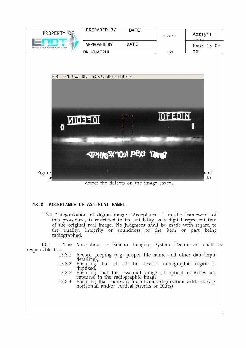
Figure 10: Using this software, user can zoom and adjust the saturation and brightness of the saved image. User also can zoom in and zoom out to detect the defects on the image saved.
13.0 ACCEPTANCE OF ASi-FLAT PANEL
13.1 Categorization of digital image “Acceptance ‘, in the framework of this procedure, is restricted to its suitability as a digital representation of the original real image. No judgment shall be made with regard to the quality, integrity or soundness of the item or part being radiographed.
13.2 The Amorphous – Silicon Imaging System Technician shall be responsible for:13.3.1 Record keeping (e.g. proper file name and other data input detailing),13.3.2 Ensuring that all of the desired radiographic region is digitized,13.3.3 Ensuring that the essential range of optical densities are captured in the
radiographic image13.3.4 Ensuring that there are no obvious digitization artifacts (e.g. horizontal
and/or vertical streaks or blurs).

PROPERTY OF PREPARED BY DATE
01
Array’s 2905
APPROVED BY DATE
DR KHAIRUL 12 FEB 2015PAGE 15 OF 20
14.0 DOCUMENTATION14.1 Documentation shall be provided to validate:
14.1.1 That the equipment and digitization requirements of this procedure have been met.
14.1.2 Calibration information and system performance demonstration including digitization standard scans or references thereto.
14.1.3 That all film degradation and artifact have been noted.14.1.4 Any missing or additional films encountered.14.1.5 Any missing or damaged reader sheets.
14.2 Radiographic Documentation Report:A radiographic documentation report shall be completed for each digitized image or set of digitized images. A report similar to the format of this procedure is required and the overall report package shall include the following as a minimum condition.14.2.1 Malaysia Nuclear Agency part number, production number, or purchase
order number applicable to the original film and film report.14.2.2 Weld identification14.2.3 Date on radiograph
