flat plate collectors - domestic heating - florida state...
TRANSCRIPT

Sustainable Energy Science and Engineering Center
Flat Plate Collectors -
Domestic Heating
Sustainable Energy Science and Engineering Center
Simplified Collector Performance Model
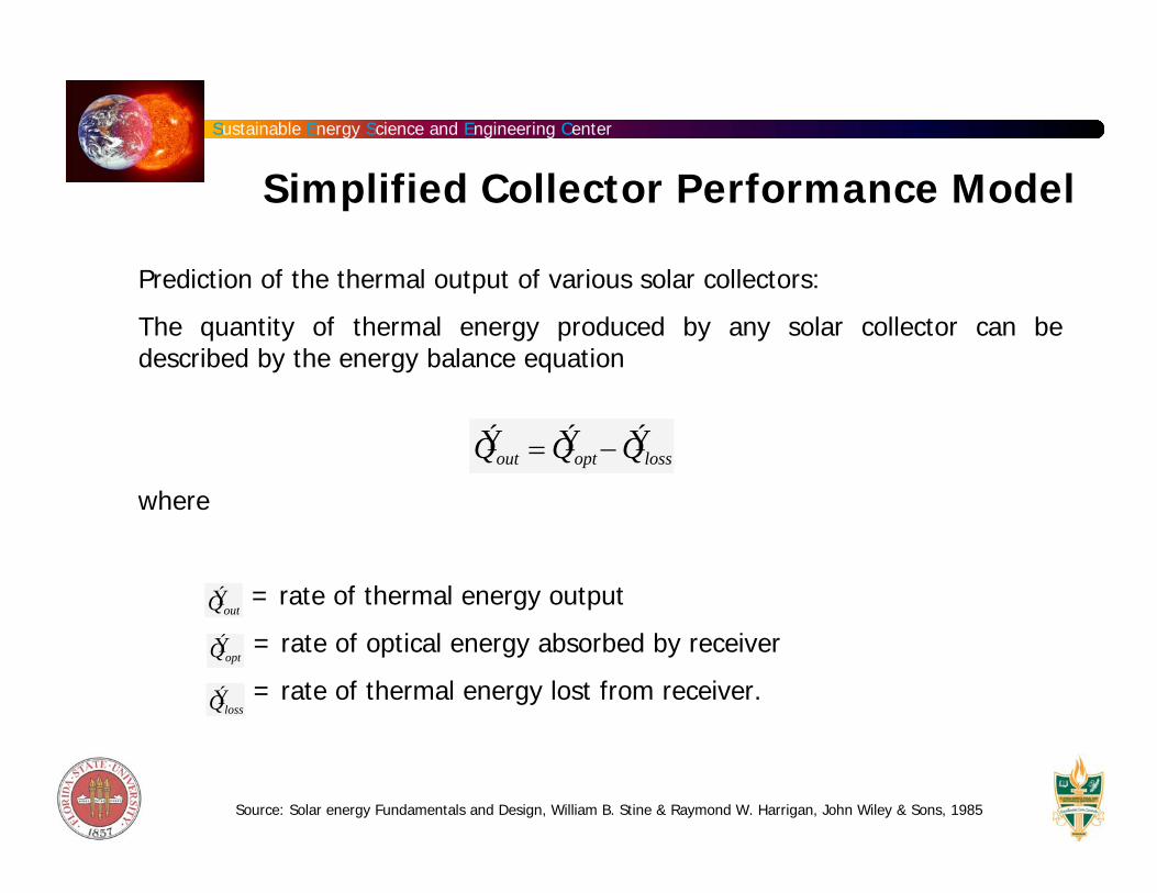
Prediction of the thermal output of various solar collectors:
The quantity of thermal energy produced by any solar collector can be described by the energy balance equation
where
= rate of thermal energy output
= rate of optical energy absorbed by receiver
= rate of thermal energy lost from receiver.
Ý Q out = Ý Q opt − Ý Q loss
Ý Q out
Ý Q opt
Ý Q loss
Source: Solar energy Fundamentals and Design, William B. Stine & Raymond W. Harrigan, John Wiley & Sons, 1985
Sustainable Energy Science and Engineering Center
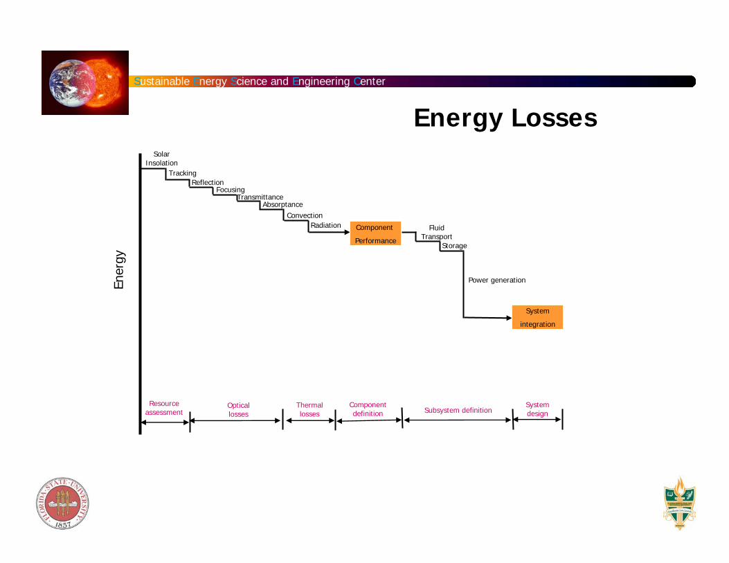
Energy LossesE n
e rg y
Solar Insolation
TrackingReflection
FocusingTransmittance
AbsorptanceConvection
Radiation Component
Performance
Fluid Transport
Storage
Power generation
System
integration
Resource assessment
Optical losses
Thermal losses
Component definition Subsystem definition
System design

Sustainable Energy Science and Engineering Center
System PerformanceU
sefu
l Ene
rgy
Prod
uced
Operating Temperature
Collector subsystemPower generation subsystem
Combined system

Sustainable Energy Science and Engineering Center
Optical Energy Absorbed by the ReceiverÝ Q opt = Aaρs,mτ gα rRSIa
Aa = specular reflectance of concentrating mirror, if any (1.0 for non-concentrating flat-plate collector)
ρs,m = transmittance of any glass envelope covering the receiver (e.g. glass cover plate in a flat-plate collector)
Aa = aperture area of the collector
S = receiver shading factor (fraction of collector aperture not shadowed by the receiver; 1.0 for a flat-plate collector)
R = receiver intercept factor (fraction of reflected beam intercepted by receiver; 1.0 for a flat-plate collector)
α r = absorbance of the receiver
Ia = isolation (irradiance) incident on collector aperture (W/m2)
S, R, αr, ρs,m and τg are constants (in a more detailed model, the dependence of the angle of the incident insolation can be considered) dependent only on the materials used and the structure accuracy of the collector - they can be lumped into a single constant term ηopt , the optical efficiency of the collector. For a flat-plate collector utilizing no reflectors, S, R and ρs,mare set equal to 1.0.

Sustainable Energy Science and Engineering Center
Thermal Energy Lost from the Receiver
Ý Q loss = ArUl Tr − Ta( )
Ar
= averaged receiver temperature (o C)Tr
= surface area of the receiver (m2)
= ambient temperature (o C)Ta
Ul = overall heat loss coefficient (W/m2 oC)
Tr =Tout + Tin
2
Tout is the temperature in degrees C of the fluid leaving the collector while Tin is the temperature of the fluid entering the collector.
The heat loss coefficient Ul is not a simple constant but instead may vary as heat-loss mechanisms change with temperature. For example as the temperature increases, radiant heat loss from the receiver increases.

Sustainable Energy Science and Engineering Center
Ý Q out = Aaηopt Ia − ArUl Tr − Ta( )
ηcol =Ý Q out
AaIa
= ηopt −Ar
Aa
UlTr − Ta( )
Ia
ηcol = ηopt −Ul
Cg
Tr − Ta( )Ia
Collector Efficiency
Where ηcol is the aperture efficiency of the collector and Ar/Aa is the geometric concentration ratio (Cg)
Cg =Aa
Ar
Aperture Receiver
Sun @ Ts
Sustainable Energy Science and Engineering Center
Reflectance of Surfaces
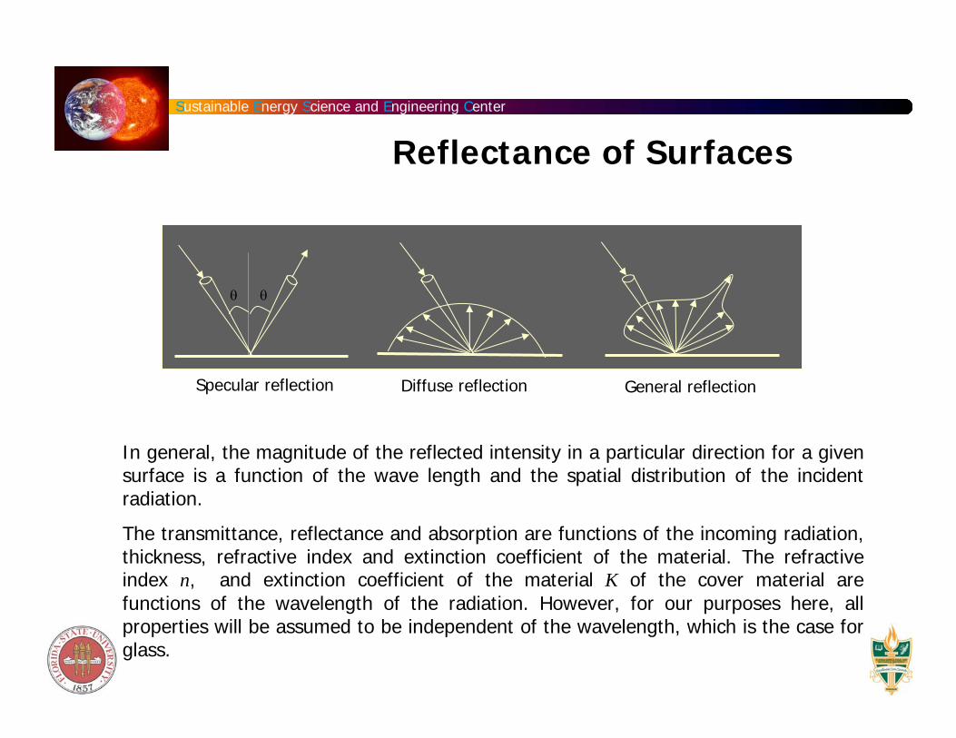
Specular reflection
θ θ
Diffuse reflection General reflection
In general, the magnitude of the reflected intensity in a particular direction for a given surface is a function of the wave length and the spatial distribution of the incident radiation.
The transmittance, reflectance and absorption are functions of the incoming radiation, thickness, refractive index and extinction coefficient of the material. The refractive index n, and extinction coefficient of the material K of the cover material are functions of the wavelength of the radiation. However, for our purposes here, all properties will be assumed to be independent of the wavelength, which is the case for glass.

Sustainable Energy Science and Engineering Center
Reflection of unpolarized Radiation:
For radiation at normal incidences:
n is the refractive index of the medium
Snell’s law
If one medium is air
Radiation Transmission and Absorption
rperpendicular = r1 =sin2 θ2 −θ1( )sin2 θ2 + θ1( )
rparallel = r2 =tan2 θ2 −θ1( )tan2 θ2 + θ1( )
r =Ir
Ii
=12
r1 + r2( )
r =n1 − n2( )2
n1 + n2( )2
r =n1 −1( )2
n1 +1( )2
n1
n2
=sinθ2
sinθ1
θ1 and θ2 are the angles of incidence and refraction

Sustainable Energy Science and Engineering Center
Neglecting absorption in the cover material and considering onlythe perpendicular or parallel component of the polarization of the incoming radiation, the transmittance can be written as:
τ1 =1− r11+ r1
τ1 = τ 2 =1− r11+ r1
Nonabsorbing Cover Transmission

Sustainable Energy Science and Engineering Center
Nonabsorbing Cover Transmission
Since the components of r1 and r2 are not equal (except at normal incidence), the transmittance of initially unpolarized radiation is the average transmission of two components,
where the subscript r is a reminder that only reflection losses are considered. For a system of N covers of the same material,
τ r =12
1− r11+ r1
+1− r2
1+ r2
⎡
⎣ ⎢
⎤
⎦ ⎥
τ rN =12
1− r11+ 2N −1( )r1
+1− r2
1+ 2N −1( )r2
⎡
⎣ ⎢
⎤
⎦ ⎥

Sustainable Energy Science and Engineering Center
ExampleThe average index of refraction of glass for the solar spectrum is 1.526. Calculate the reflectance of one surface of glass at normal incidence and at 60 degrees. Also calculate the transmittance of two covers ofnonabsorbing glass at normal incidence and at 60 degrees.
At normal incidence:
At an incidence angle of 60o
r =n1 − n2( )2
n1 + n2( )2 =0.5262.526
⎛ ⎝ ⎜
⎞ ⎠ ⎟
2
= 0.0434
θ2 = sin−1 sin601.526
⎛ ⎝ ⎜
⎞ ⎠ ⎟ = 34.58
r =12
r1 + r2( )=12
sin2 −25.42( )sin2 94.58( )
+tann2 −25.42( )tann2 94.58( )
⎡
⎣ ⎢
⎤
⎦ ⎥ = 0.093
τ r 0( )= 1− 0.04341+ 3(0.0434)
= 0.85
τ r 60( )= 12
1− 0.1851+ 3(0.185)
+ 1− 0.0011+ 3(0.001)
⎡
⎣ ⎢ ⎤
⎦ ⎥ = 0.76
Sustainable Energy Science and Engineering Center
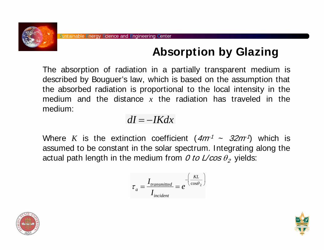
The absorption of radiation in a partially transparent medium isdescribed by Bouguer’s law, which is based on the assumption that the absorbed radiation is proportional to the local intensity in the medium and the distance x the radiation has traveled in the medium:
Where K is the extinction coefficient (4m-1 ~ 32m-1) which is assumed to be constant in the solar spectrum. Integrating along the actual path length in the medium from 0 to L/cos θ2 yields:
Absorption by Glazing
τ a =Itransmitted
Iincident
= e−
KLcosθ 2
⎛
⎝ ⎜
⎞
⎠ ⎟
dI = −IKdx

Sustainable Energy Science and Engineering Center
Optical Properties of Cover Systems
τ perpendicular = τ a
1− rperpendicular
1+ rperpendicular
1− rperpendicular2
1− (rperpendicularτ a )2
⎛
⎝ ⎜ ⎜
⎞
⎠ ⎟ ⎟
ρperpendicular = rperpendicular(1+ τ aτ perpendicular)
α perpendicular = (1− τ a )1− rperpendicular
1− rperpendicularτ a
⎛
⎝ ⎜ ⎜
⎞
⎠ ⎟ ⎟
Transmittance
Reflectance
Absorptance
For practical collector covers: τa > 0.9 and r = 0.1
The transmittance of a single cover ≈ τaτr
The absorptance of the collector cover , α ≈1− τa
The reflectance of a single cover , ρ ≈τa-τ

Sustainable Energy Science and Engineering Center
Calculate the transmittance, reflectance and absorptance of a single glass cover 2.3 mm thick at an angle of 60 degrees. The extinction coefficient of the glass is 32 m-1.
At an incidence angle of 60o, the optical path length is
Example
KLcosθ2
= 32 ×0.0023
cos34.58= 0.0894
Refraction angle calculated in an earlier example.
τ a = e−0.0894 = 0.915
The transmittance is found by averaging the transmittance of the parallel and perpendicular components of polarization or simply:
The reflectance is found:
The absorptance is found to be:
The above results are also valid to identical multiple covers. The length L equal to the total cover system thickness.
τ =0.915
21− 0.1851+ 0.185
+1− 0.0011+ 0.001
⎡ ⎣ ⎢
⎤ ⎦ ⎥ = 0.771
α =1− 0.915 = 0.085
ρ =1− 0.771− 0.085 = 0.144

Sustainable Energy Science and Engineering Center
Transmittance-absorption Product (τα):
Transmittance of the cover system at the desired angle = τ
The angular absorption of the absorber plate = α
Of the incident energy, τα is absorbed by the absorber plate and (1- α) τ is reflected back to the cover system. The reflection from the absorber plate is diffusive.
Transmission - Absorption
ρd refers to the reflectance of the cover system for diffuse radiation incident from the bottom side and can be estimated to be the difference between τa and τ at an angle 60o. The fraction of the incident energy ultimately absorbed is:
τα =τα
1− 1−α( )ρd

Sustainable Energy Science and Engineering Center
Transmittance-absorption Product

Sustainable Energy Science and Engineering Center
Basic Flat-Plate Collector

Sustainable Energy Science and Engineering Center
Liquid Flat Plate Collector
Absorber Plate: Insolation passing through the glazing is absorbed directly on the absorber plate. Surface coatings with high absorptance for visible light are used on the absorber. The resulting black surface typically absorbs over 95% of the incident solar radiation.
Fin heat removal: The second function of the absorber plate is to transfer the absorbed energy into heat transfer fluid - done by conducting the absorbed heat to tubes that contain the heat transfer fluid - typical water or water with antifreeze). Difference between the absorber surface temperature and working fluid must be kept to minimum. The fin should be thick enough to accomplish this.
Tubes should be thin walled and of high thermal conductivity material
The tube should be brazed or welded to the absorber sheet to minimize thermal contact resistance.
The tube and the absorber sheet should be of similar material to prevent galvanic corrosion between them.
Tubes should not be placed too far apart to avoid higher temperature difference between the tip of the fin (midway between the tubes) and the base.

Sustainable Energy Science and Engineering Center
Flat-Plate Collectors
In the solar collector, the energy transfer is from source of radiant energy to a fluid.
The flux of incident radiation ~ 1000 W/m2 ( it is variable)
The wavelength range: 0.3 - 3.0 μm
Energy delivery at moderate temperatures ~ 400K
Use both beam and diffusive solar radiation - do not require tracking the Sun.
Major applications: solar water heating, building heating, air conditioning and industrial process heat.
Maximum temperature ~ 400K
Source: Solar Engineering of Thermal processes by Duffie & Beckman, chapter 6.

Sustainable Energy Science and Engineering Center
The solar radiation absorbed by a collector per unit area of absorber S is equal to the difference between the incident solar radiation and the optical losses and is given by the expression:
Where (1+cos b)/2 and (1-cos b)/2 are the view factors from the collector to the sky and from the collector to the ground respectively. The subscripts b, d, and g represent beam, diffuse and ground.
τα = transmittance -absorption product - a property of a cover-absorber combination.
The geometric factor Rb is the ratio of beam radiation on the tilted surface to that on a horizontal surface.
I is the solar radiation J/m2 and rg is the ground reflectance
Absorbed Radiation
S = IbRb τα( )b + Id τα( )d
1+ cosβ2
⎛ ⎝ ⎜
⎞ ⎠ ⎟ + ρg Ib + Id( ) τα( )g
1− cosβ2
⎛ ⎝ ⎜
⎞ ⎠ ⎟

Sustainable Energy Science and Engineering Center
The thermal energy lost from the collector to the surroundings by conduction, convection and infrared radiation = UL(Tpm-Ta)
Where, UL is the heat transfer coefficient, Tpm and Ta are mean absorber plate temperature and ambient temperature respectively.
In steady state the useful energy out put of a collector of area Ac :
Tpm is difficult to calculate or measure since it is a function of collector design, the incident solar radiation and the entering fluid conditions.
Collector performance:
Incident total solar energy
Qu = Ac S −UL Tpm − Ta( )[ ]
η =Qudt∫
Ac GT dt∫
Energy Balance

Sustainable Energy Science and Engineering Center
Collector heat removal factor : Relates the actual useful energy gain of a collector to the useful gain if the whole collector surface were at the fluid inlet temperature.
where Uo is the heat transfer resistance from the fluid to the ambient air.
Collector flow factor:
FR =Ý m Cp
AcUL
1− exp −ACULF '
Ý m Cp
⎛
⎝ ⎜ ⎜
⎞
⎠ ⎟ ⎟
⎡
⎣ ⎢ ⎢
⎤
⎦ ⎥ ⎥
F ' =Uo
UL
F '' =FR
F '
Energy Balance
Qu = AcFR S −UL Ti − Ta( )[ ]

Sustainable Energy Science and Engineering Center
Collector Efficiency Factor

Sustainable Energy Science and Engineering Center
Collector Flow Factor

Sustainable Energy Science and Engineering Center
Where Ti is the inlet fluid temperature and FR is the heat removal factor.
Instantaneous efficiency:
GT is given in W/m2
Qu = AcFR S −UL Ti − Ta( )[ ]
ηi =Qu
AcGT
=FR GT τα( )av −UL (Ti − Ta )[ ]
GT
Energy Balance

Sustainable Energy Science and Engineering Center
Problem: Calculate the daily useful gain and efficiency of 10 solar collector modules installed “optimally” (first determine the optimum orientation) in parallel at the college of engineering. The hourly radiation on the plane of the collector IT, the hourly radiation absorbed by the absorber plate S, and the hourly ambient temperature Ta are given in the table. For the collector assume the overall loss coefficient UL to be 8 W/m2C and the plate efficiency factor F’ to be 0.841. The flow rate through each 1x2m collector panel is o.03 kg/s and the inlet fluid temperature remains constant at 40oC.
Reference: Chapters 5 & 6 of Solar engineering of thermal processes, Duffie & Beckman, 2nd edition, Wiley Interscience, 1991.

Sustainable Energy Science and Engineering Center
Solar Collector Parameters

Sustainable Energy Science and Engineering Center
Liquid Heating Collector System

Sustainable Energy Science and Engineering Center
Determination of instantaneous h with beam radiation nearly normal to the absorbing surface.
Determination of effects of angle of incidence of the solar radiation.
Determination of collector time constant - a measure of effective heat capacity.
The useful gain:
Measure the fluid inlet and outlet temperatures and the fluid flow rate.
Collector Characterization
Qu = Ý m Cp To − Ti( )

Sustainable Energy Science and Engineering Center
Water Heater Configurations
Natural circulation systemOne tank forced circulation system
Antifreeze loop and internal heat exchanger
Antifreeze loop and external heat exchanger

Sustainable Energy Science and Engineering Center
Design Problem Using TRNSYS
A transient process simulation program for the study of solar processes and its applications
Thermal performance of solar water heaterDevelop a two cover collector design for a hot water load of 3000kg water/day at a minimum temperature of 335K evenly distributed between the hours of 0700-2100. Solar collector total effective area = 65 m2. The collector is designed to operate in Tallahassee.