flexible circuits, inc.flexiblecircuits.net/fcimanufguide2009.pdf · flexible circuits, inc. ......
TRANSCRIPT
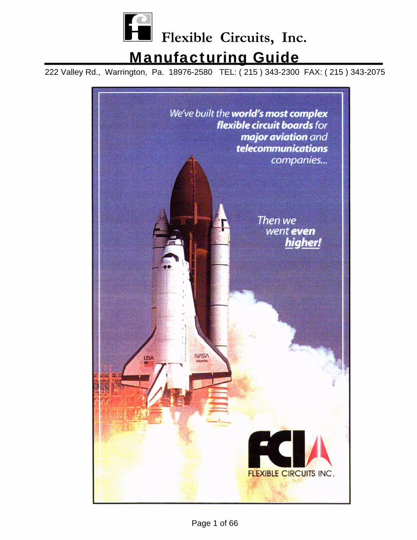
Flexible Circuits, Inc. Manufacturing Guide
222 Valley Rd., Warrington, Pa. 18976-2580 TEL: ( 215 ) 343-2300 FAX: ( 215 ) 343-2075
Page 1 of 66
Flexible Circuits, Inc. Manufacturing Guide
222 Valley Rd., Warrington, Pa. 18976-2580 TEL: ( 215 ) 343-2300 FAX: ( 215 ) 343-2075
Page 2 of 66
Foreword
Flexible Circuits, Inc. produces high reliability flexible printed wiring interconnects. We are a MIL-P-50884 and IPC 6013 certified manufacturer. To provide this type of performance level, certain manufacturing techniques and proper material selection are crucial for the manufacture of and optimizing field performance. This guide along with direct contact with Flexible Circuits, Inc. will provide the necessary information required for achieving a successful interconnect package from concept through installation.
Flexible Circuits, Inc. Manufacturing Guide
222 Valley Rd., Warrington, Pa. 18976-2580 TEL: ( 215 ) 343-2300 FAX: ( 215 ) 343-2075
Page 3 of 66
INDEX
Pages Introduction ……………………………………………………………………………. 4-5 Specifications …………………………………………………………………………. 6-15 Materials ……………………………………………………………………………….. 16-24 Construction ………………………………………………………………………….. 25-31 Artwork …………………………………………………………………………………. 32-41 Miscellaneous: Stiffener/Reinforcements ………………………………………………….. 43-44
Desmear/Etchback …………………………………………………………. 45-46 Dynamic Flexing …………………………………………………………….. 47 Silver Epoxy Shielding …………………………………………………….. 48-49 Surface Mount ……………………………………………………………….. 50 Bookbind ……………………………………………………………………… 51-54 Heat Sinks …………………………………………………………………….. 55 Pad Only Plating …………………………………………………………….. 56 Solder Mask ………………………………………………………………….. 57 Eccobond Fillet (Rigid/Flex Transition Zone) ………………………….. 58 Laser Cutting/Skiving ………………………………………………………. 59 Data Sheets …………………………………………………………………………… 60-68
Flexible Circuits, Inc. Manufacturing Guide
222 Valley Rd., Warrington, Pa. 18976-2580 TEL: ( 215 ) 343-2300 FAX: ( 215 ) 343-2075
Page 4 of 66
Flexible Circuit or Rigid Board? The most compelling difference between flexible circuits versus rigid circuits is flexibility. Flexible circuits are usually much thinner and are able to conform to the spacing limitations and environments into which they are installed. Advantages of using flexible circuitry: 1) They can conform to three dimensional spacing limitations. 2) They have mobility (can be used where movement is required). 3) They are much thinner, thus more conductive layers can be added and will fit into tighter spaces. 4) They are much lighter in weight. Disadvantages of using flexible circuitry: 1) They are generally much more expensive as a unit price. 2) They are more fragile. They can be subject to tearing if not properly handled. 3) Installation of terminals, connectors, etc. may require an additional stiffening material bonded to the flexible circuit. 4) “Z” axis expansion must be addressed during thermal exposure.
Flexible Circuits, Inc. Manufacturing Guide
222 Valley Rd., Warrington, Pa. 18976-2580 TEL: ( 215 ) 343-2300 FAX: ( 215 ) 343-2075
Page 5 of 66
Flexible Circuit or Round Wire? Perhaps a short review of the advantages of flexible circuitry will help you make a decision. 1. Less weight and bulk when used as a direct round wire replacement. 2. It will virtually eliminate wiring errors and subsequently eliminates trouble shooting. 3. When all the costs of manufacturing, assembly, installation, and trouble shooting/repair are considered, a lower “end-use cost” is usually obtained with flexible circuitry. 4. Better electrical performance with higher speeds and better shielding of signals. 5. Greater environmental resistance against corrosion, moisture and other atmosphere hazards because of the encapsulation of the copper conductors. 6. Improved durability because the materials used are highly resistant to flexing and tension. 7. Better adaptability. Able to fit into operational configurations where printed circuit boards simply cannot fit.
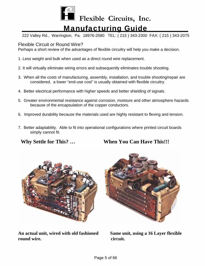
Why Settle for This? … When You Can Have This!!!
An actual unit, wired with old fashioned Same unit, using a 16 Layer flexible round wire. circuit.
Flexible Circuits, Inc. Manufacturing Guide
222 Valley Rd., Warrington, Pa. 18976-2580 TEL: ( 215 ) 343-2300 FAX: ( 215 ) 343-2075
Page 6 of 66
SPECIFICATIONS
Flexible Circuits, Inc. Manufacturing Guide
222 Valley Rd., Warrington, Pa. 18976-2580 TEL: ( 215 ) 343-2300 FAX: ( 215 ) 343-2075
Page 7 of 66
The industry generally had accepted two specifications for the manufacture of flexible printed wiring
boards, “MIL-P-50884” for military/aerospace field and “IPC” for industrial/commercial/medical fields. Today the industry is moving away from the military specifications and adopting the “IPC” specifications. IPC has created a complete array of specifications for manufacturing, assembling, and testing of flexible printed wiring boards for all performance levels. “IPC-6013” is the new fabrication and performance specification for flexible printed wiring boards that replaces MIL-P-50884. Below is a list of the MIL-Specs and the IPC-Specs most commonly referenced:
MIL-SPECS & Other Publications MIL-P-50884 Flex Manufacturing and Performance (Inactive for new designs) MIL-STD-2118 Flex Design Standard (Inactive for new designs) MIL-STD-105 Sampling Procedures and Inspection Tables MIL-STD-129 Marking for Shipment and Storage MIL-STD-130 Identification for Marking MIL-STD-202 Test Methods for Electronic Equipment MIL-STD-45662 Calibration System Requirements DOD-D-1000 Engineering Drawings DOD-STD-100 Engineering Drawing Practices ANSI-Y-14.5 Dimensioning and Tolerancing MIL-C-14550 Copper Plating (Electrodeposited) ASTM-B-488 Gold Plating (Electrodeposited) MIL-I-45208 Inspection System Requirements MIL-Q-9858 Quality Program Requirements ASTM-B-579 Plating Tin Lead (Electrodeposited) MIL-P-55110 Printed Wiring Boards (inactive for new designs) SAE-AMS-2424 Nickel Plating (Electrodeposited)
Flexible Circuits, Inc. Manufacturing Guide
222 Valley Rd., Warrington, Pa. 18976-2580 TEL: ( 215 ) 343-2300 FAX: ( 215 ) 343-2075
Page 8 of 66
IPC-SPECS
IPC-6011 Generic Performance Specification for Printed Boards IPC-6013 Qualification and Performance Specification for Flexible Printed Boards IPC-T-50 Terms and Definitions IPC-4562 Copper Foil for Printed Wiring Applications IPC-4101 Specification for Base Materials for Rigid and Multilayer Printed Boards IPC-4103 Specification for Base Materials for High Speed/High Frequency Applications IPC-4202 Flexible Bare Dielectrics for Use in Flexible Printed Wiring IPC-4203 Adhesive Coated Dielectric Films For Use in Fabrication of Flexible Printed Wiring IPC-4204 Metal Clad Dielectrics for use in Fabrication of Flexible Printed Wiring IPC-4552 Electroless Nickel/Immersion Gold Plating for Electronic Interconnections IPC-SM-840 Qualification and Performance of Permanent Solder Mask IPC-2221 Generic Standard on Printed Board Design IPC-2223 Sectional Design Standard for Flexible Printed Boards IPC-6012 Qualification and Performance Specification for Rigid Printed Boards IPC-9252 Requirements for Electrical Testing of Unpopulated Printed Boards J-STD-001 Requirements for Soldered Electrical and Electronics Assemblies J-STD-002 Solderability Tests for Component Leads, Terminations, Lugs, Terminals and Wires J-STD-003 Solderability Tests for Printed Boards J-STD-004 Requirements for Soldering Fluxes J-STD-005 General Requirements and Test Methods for Electronic Grade Solder Paste J-STD-006 General Requirements and Test Methods for Soft Solder Alloys and Fluxed and Non-Fluxed Solid Solder for Electronic Soldering Applications.
Flexible Circuits, Inc. Manufacturing Guide
222 Valley Rd., Warrington, Pa. 18976-2580 TEL: ( 215 ) 343-2300 FAX: ( 215 ) 343-2075
Page 9 of 66
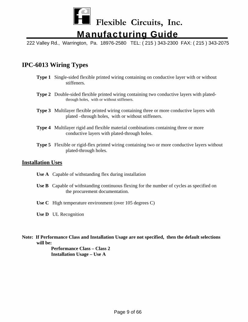
IPC-6013 Wiring Types Type 1 Single-sided flexible printed wiring containing on conductive layer with or without stiffeners. Type 2 Double-sided flexible printed wiring containing two conductive layers with plated- through holes, with or without stiffeners. Type 3 Multilayer flexible printed wiring containing three or more conductive layers with plated –through holes, with or without stiffeners. Type 4 Multilayer rigid and flexible material combinations containing three or more conductive layers with plated-through holes. Type 5 Flexible or rigid-flex printed wiring containing two or more conductive layers without plated-through holes. Installation Uses Use A Capable of withstanding flex during installation Use B Capable of withstanding continuous flexing for the number of cycles as specified on the procurement documentation. Use C High temperature environment (over 105 degrees C) Use D UL Recognition Note: If Performance Class and Installation Usage are not specified, then the default selections will be: Performance Class – Class 2 Installation Usage – Use A
Flexible Circuits, Inc. Manufacturing Guide
222 Valley Rd., Warrington, Pa. 18976-2580 TEL: ( 215 ) 343-2300 FAX: ( 215 ) 343-2075
Page 10 of 66
IPC-4101 Specification for Base Materials for Rigid and Multilayer Printed Boards As the Printed Circuit Industry moves away from Military Specifications, this created a need for an IPC specification for rigid materials. This specification covers the performance requirements for rigid laminates and prepregs used for the manufacture of rigid boards, rigid multilayer boards and flexible rigid/flex boards. This specification is based on the canceled specification MIL-S-13949. It basically provides the industry with performance criteria that is equivalent to MIL-S-13949. However, it eliminates some of the redundant testing and costs associated with those tests. What does this mean to the User? Basically no impact except that drawings should now specify the above materials to be per IPC-4101 in lieu of canceled MIL-S-13949. Certification can only be made to IPC-4101. There is no longer any certification to MIL-S-13949. Shown in the next pages are the major differences between the IPC-4101 and MIL-S-13949.
Flexible Circuits, Inc. Manufacturing Guide
222 Valley Rd., Warrington, Pa. 18976-2580 TEL: ( 215 ) 343-2300 FAX: ( 215 ) 343-2075
Page 11 of 66
Comparison of the IPC-4101 to the canceled MIL-S13949 (major highlighted differences) General Information Differences Prepregs and laminates are on the same slash sheet. Slash sheets are recognized by “families” with open spaces for new materials that fit that family. The entire specification is in metric with no English references. The latest test methods are attached to the document. Paragraph 1.2.2 Laminates can be ordered as dielectric space (without copper foil) or as an overall thickness (Including copper foil). Currently laminates can only be ordered as a dielectric space. Table 1 The copper foil table now includes type “R” (reverse treated electrodeposited) for grade 1 and Type “S” (reverse treated electrodeposited) for grade 3. Paragraph 1.2.5 and 3.8.3.1.2 Surface quality class now includes a “D” designation that provides the most stringent surface quality call out. No pits, dents or epoxy spots over 5 mils. MIL-S-13949 has “B” as the tightest class which allow 1 pit up to 15 mils. Paragraph 1.2.7 Prepregs are ordered using 3 parameters (resin content, resin flow, and the “optional” parameter) Prepregs can be tested by using new test methods such as rheology, % cure, or delta H. Paragraph 3.1.2 Quality conformance testing is conducted as determined by the current Manufacturers Quality System. Changes in the testing frequencies can be made by following the guidelines in IPC-PC-90. In the absence of a “Manufacturing Quality System”, conformance testing is conducted at the same frequency as MIL-S-13949.
Flexible Circuits, Inc. Manufacturing Guide
222 Valley Rd., Warrington, Pa. 18976-2580 TEL: ( 215 ) 343-2300 FAX: ( 215 ) 343-2075
Page 12 of 66
Paragraph 3.1.5 and 3.3 Self-declaration form IPC-LQP-1730 is a pre-requisite to certifying to IPC-4101. The document IPC-LQP-1730 will be published by the IPC at the same time as the IPC-4101 Specification Paragraph 3.1.7 and 3.4 Qualification sample testing must be conducted by the supplier at any IPC-QL-653 approved laboratory. The qualification data must be summarized and readily available for review. The qualification testing regime is the same as prescribed by MIL-S-13949. Paragraph 3.4.1 A “thin” laminate specimen 10 mils or less qualifies all thin laminates (30 mils or less). A “thick” laminate specimen greater than 30 mils qualifies all thick laminates. Paragraph 3.4.2 For a given slash sheet, the thinnest prepreg qualifies all the thicker prepregs. Table 5 Table 5 now includes Delta Tg and average X/Y CTE as optional tests. The test method for flammability has been changed from the “MIL” method to the standard “UL” method 94. Table 6 Electrical tests and some environmental tests are performed on prepregs after pressing into a Thin laminate. Prepreg testing for flammability is only conducted as a thin laminate specimen. Paragraph 3.9.1.1 Peel strength is called out as a single value for 35 micron foil. Foil weight greater than 35 microns must meet the required value for 35 micron. Foils less than 35 micron may be plated up to 35 micron and tested as is the current specified procedure in MIL-S-13949.
Flexible Circuits, Inc. Manufacturing Guide
222 Valley Rd., Warrington, Pa. 18976-2580 TEL: ( 215 ) 343-2300 FAX: ( 215 ) 343-2075
Page 13 of 66
Paragraph 3.9.1.2 Dimensional stability is now specified as a nominal value with a tolerance range. The supplier must provide the nominal value for dimensional stability for each construction. Currently the MIL-S-13949 specification uses zero as the nominal value. IPC-4101 will reward consistency of dimensional movement. Paragraph 3.9.2.2.6 Gel time is an optional test. It can be replaced with other characterization tests if desired such As rheological flow, cure %, or Delta H. Paragraph 3.9.2.2.8 Volatile content is an optional test. Paragraph 3.10.2.3 Dicy Crystals is an optional test. Paragraph 3.15 MSDS forms must be available for materials supplied under this specification. Paragraph 5.2 The supplier is responsible for establishing written guidelines for their authorized distributors.
Flexible Circuits, Inc. Manufacturing Guide
222 Valley Rd., Warrington, Pa. 18976-2580 TEL: ( 215 ) 343-2300 FAX: ( 215 ) 343-2075
Page 14 of 66
MATERIALS
Flexible Circuits, Inc. Manufacturing Guide
222 Valley Rd., Warrington, Pa. 18976-2580 TEL: ( 215 ) 343-2300 FAX: ( 215 ) 343-2075
Page 15 of 66
Selection of Materials Materials are one of the most important ingredient in determining the circuit’s performance and life expectancy. Materials should be selected based upon the following criteria:
What is the circuit’s function? What environment will the circuit be expected to operate in? What is the interconnection method? What is the life expectancy? What is the cost to produce?
FCI has a vast knowledge and experience in matching the right material for the particular application. We use only the highest grades of materials. These next pages will describe these materials and their performance.
Flexible Circuits, Inc. Manufacturing Guide
222 Valley Rd., Warrington, Pa. 18976-2580 TEL: ( 215 ) 343-2300 FAX: ( 215 ) 343-2075
Page 16 of 66
Flexible Metal Clad Laminate
Flexible Metal Clad Laminates provide the base material (conductive and dielectric layers) for upon which flexible printed wiring boards can be manufactured.
Types: Types are listed in IPC-4204. There are two (2) types of laminates that are typically used:
1) A composite of polyimide film, acrylic adhesive, and copper foil. 2) A composite of polyimide film and copper foil (no adhesive, this is commonly
Referred to as “adhesive-less” laminate. The first type is still the workhorse of the industry and is mostly used on Types 1, 2, 3, 5 and low layer count Type 4 (rigid/flex) application. The second type is becoming more widely used especially on high layer count Type 4’s where excessive “z-axis” expansion of the materials during thermal exposure can cause plated- through hole failure. There are other areas where this material proves to be advantageous such as in high dynamic flexing applications. Material Availability Maximum sheet size (in.) 24 x 36 (FCI typically uses 18 x24 sheets) Polyimide film thickness (mils) 1, 2, 3, 4, 5 or 6 Copper foil weight (oz.) ½, 1, or 2 Adhesive thickness (mils) 1 *Other materials are available as special orders *Adhesive is available with a flame retardant called “FR” type *FCI uses double treated copper as a standard
Flexible Circuits, Inc. Manufacturing Guide
222 Valley Rd., Warrington, Pa. 18976-2580 TEL: ( 215 ) 343-2300 FAX: ( 215 ) 343-2075
Page 17 of 66
Adhesive Coated Kapton (Coverfilm)
Adhesive coated Kapton is the material used for providing a dielectric layer over the flexible printed wiring conductive surfaces.
Types:
Types are listed in IPC-4203. Typical only one type is used; Kapton coated with Acrylic adhesive. This material is used for all applications (Types 1, 2, 3, 4, and 5).
Material Availability Standard Roll size 24” wide Polyimide film thickness (mils) ½, 1, 2, 3, or 5 Adhesive thickness (mils) ½, 1, 2, or 3 *Other materials are available as special orders *Adhesive is available with a flame retardant called “FR” type Flexible Adhesives Flexible Adhesives are used to laminate various flexible materials together. This could be to laminate multiple flexible layers, attachment of stiffeners, heat sinks ,etc. Types: Types are listed in IPC-4203. Typically only one type is; Acrylic adhesive. This material is
used for all applications (Types 1, 2, 3, 4, and 5). Other types are available, however FCI’s use is very minimal.
Material Availability Standard Roll size 24” wide (FCI typically uses 18 x24 sheets) Adhesive thickness (mils) 1, 2, or 3 *Adhesive is available with a flame retardant called “FR” type
Flexible Circuits, Inc. Manufacturing Guide
222 Valley Rd., Warrington, Pa. 18976-2580 TEL: ( 215 ) 343-2300 FAX: ( 215 ) 343-2075
Page 18 of 66
Rigid Laminates Rigid Laminate is a glass cloth coated with a resin system subsequently laminated to copper foil. This material is used by the flexible printed wiring industry for rigid/flex applications
providing the base material (conductive and dielectric layers) for upon which rigid printed wiring conductive layers can be produced. It also used as “stiffener” material for the flexible circuit.
Types:
Types are listed in IPC-4101. There are many types of Rigid Laminates available to the industry. The most commonly used are Types GF and GI. Type GF is an “epoxy” resin system that is typically used for low layer count rigid/flex and stiffener applications. Type GI is used in high layer count rigid/flex applications where greater thermal resistance is required.
Material Availability Standard sheet size (in.) 36 x 48 (FCI typically uses 18 x24) Core thickness (mils) 5, 8, 10, 14, 20, 31, 47, 62, 93 Copper foil thickness (oz.) ½, 1, 2, *Other materials are available as special orders
Flexible Circuits, Inc. Manufacturing Guide
222 Valley Rd., Warrington, Pa. 18976-2580 TEL: ( 215 ) 343-2300 FAX: ( 215 ) 343-2075
Page 19 of 66
Prepreg Prepreg is a glass cloth coated with a resin system not fully cured (B-staged) to allow for subsequent
lamination. This material is used by the flexible printed wiring industry for rigid/flex applications as an adhesive and dielectric to laminate conductive layers together.
Types:
Types are listed in IPC-4101. There are many types of Prepregs available to the industry. The most commonly used are Types GF and GI. Type GF is an “epoxy” resin system that is typically used for low layer count rigid/flex and stiffener applications. Type GI is used in high layer count rigid/flex applications where greater thermal resistance is required. Most of the Prepreg used for this application is a “No Flow” type.
Material Availability Standard Roll size (in.) 36” wide (FCI typically uses 18 x24 sheets) Glass Styles 106, 1080, 2112, 2116, 7628 *Other materials are available as special orders
Flexible Circuits, Inc. Manufacturing Guide
222 Valley Rd., Warrington, Pa. 18976-2580 TEL: ( 215 ) 343-2300 FAX: ( 215 ) 343-2075
Page 20 of 66
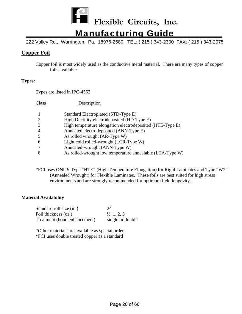
Copper Foil Copper foil is most widely used as the conductive metal material. There are many types of copper foils available. Types: Types are listed in IPC-4562
Class Description 1 Standard Electroplated (STD-Type E) 2 High Ductility electrodeposited (HD-Type E) 3 High temperature elongation electrodeposited (HTE-Type E) 4 Annealed electrodeposited (ANN-Type E) 5 As rolled wrought (AR-Type W) 6 Light cold rolled-wrought (LCR-Type W) 7 Annealed-wrought (ANN-Type W) 8 As rolled-wrought low temperature annealable (LTA-Type W)
*FCI uses ONLY Type “HTE” (High Temperature Elongation) for Rigid Laminates and Type “W7” (Annealed Wrought) for Flexible Laminates. These foils are best suited for high stress environments and are strongly recommended for optimum field longevity.
Material Availability Standard roll size (in.) 24 Foil thickness (oz.) ½, 1, 2, 3 Treatment (bond enhancement) single or double *Other materials are available as special orders *FCI uses double treated copper as a standard
Flexible Circuits, Inc. Manufacturing Guide
222 Valley Rd., Warrington, Pa. 18976-2580 TEL: ( 215 ) 343-2300 FAX: ( 215 ) 343-2075
Page 21 of 66
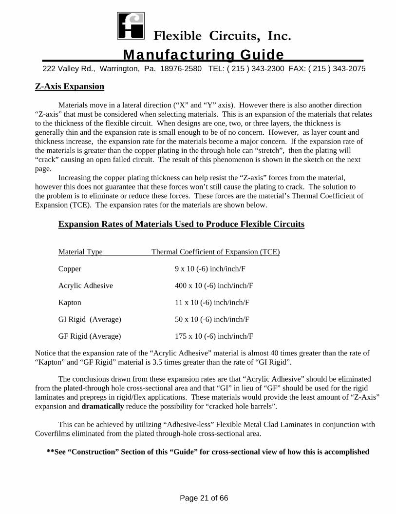
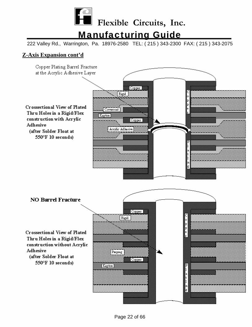
Z-Axis Expansion Materials move in a lateral direction (“X” and “Y” axis). However there is also another direction “Z-axis” that must be considered when selecting materials. This is an expansion of the materials that relates to the thickness of the flexible circuit. When designs are one, two, or three layers, the thickness is generally thin and the expansion rate is small enough to be of no concern. However, as layer count and thickness increase, the expansion rate for the materials become a major concern. If the expansion rate of the materials is greater than the copper plating in the through hole can “stretch”, then the plating will “crack” causing an open failed circuit. The result of this phenomenon is shown in the sketch on the next page.
Increasing the copper plating thickness can help resist the “Z-axis” forces from the material, however this does not guarantee that these forces won’t still cause the plating to crack. The solution to the problem is to eliminate or reduce these forces. These forces are the material’s Thermal Coefficient of Expansion (TCE). The expansion rates for the materials are shown below.
Expansion Rates of Materials Used to Produce Flexible Circuits Material Type Thermal Coefficient of Expansion (TCE)
Copper 9 x 10 (-6) inch/inch/F
Acrylic Adhesive 400 x 10 (-6) inch/inch/F
Kapton 11 x 10 (-6) inch/inch/F
GI Rigid (Average) 50 x 10 (-6) inch/inch/F
GF Rigid (Average) 175 x 10 (-6) inch/inch/F
Notice that the expansion rate of the “Acrylic Adhesive” material is almost 40 times greater than the rate of “Kapton” and “GF Rigid” material is 3.5 times greater than the rate of “GI Rigid”.
The conclusions drawn from these expansion rates are that “Acrylic Adhesive” should be eliminated from the plated-through hole cross-sectional area and that “GI” in lieu of “GF” should be used for the rigid laminates and prepregs in rigid/flex applications. These materials would provide the least amount of “Z-Axis” expansion and dramatically reduce the possibility for “cracked hole barrels”.
This can be achieved by utilizing “Adhesive-less” Flexible Metal Clad Laminates in conjunction with Coverfilms eliminated from the plated through-hole cross-sectional area. **See “Construction” Section of this “Guide” for cross-sectional view of how this is accomplished
Flexible Circuits, Inc. Manufacturing Guide
222 Valley Rd., Warrington, Pa. 18976-2580 TEL: ( 215 ) 343-2300 FAX: ( 215 ) 343-2075
Page 22 of 66
Z-Axis Expansion cont’d
Flexible Circuits, Inc. Manufacturing Guide
222 Valley Rd., Warrington, Pa. 18976-2580 TEL: ( 215 ) 343-2300 FAX: ( 215 ) 343-2075
Page 23 of 66
CONSTRUCTIONS
Flexible Circuits, Inc. Manufacturing Guide
222 Valley Rd., Warrington, Pa. 18976-2580 TEL: ( 215 ) 343-2300 FAX: ( 215 ) 343-2075
Page 24 of 66
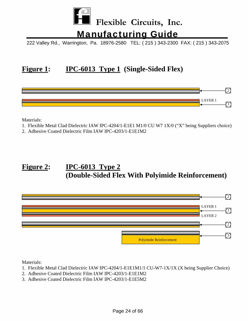
Figure 1: IPC-6013 Type 1 (Single-Sided Flex)
LAYER 1
2
1 Materials: 1. Flexible Metal Clad Dielectric IAW IPC-4204/1-E1E1 M1/0 CU W7 1X/0 (“X” being Suppliers choice) 2. Adhesive Coated Dielectric Film IAW IPC-4203/1-E1E1M2
Figure 2: IPC-6013 Type 2 (Double-Sided Flex With Polyimide Reinforcement)
LAYER 11
LAYER 2
2
2
3Polyimide Reinforcement
Materials: 1. Flexible Metal Clad Dielectric IAW IPC-4204/1-E1E1M1/1 CU-W7-1X/1X (X being Supplier Choice) 2. Adhesive Coated Dielectric Film IAW IPC-4203/1-E1E1M2 3. Adhesive Coated Dielectric Film IAW IPC-4203/1-E1E5M2
Flexible Circuits, Inc. Manufacturing Guide
222 Valley Rd., Warrington, Pa. 18976-2580 TEL: ( 215 ) 343-2300 FAX: ( 215 ) 343-2075
Page 25 of 66
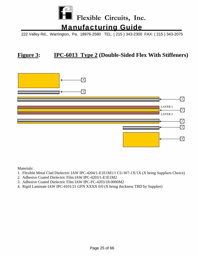
Figure 3: IPC-6013 Type 2 (Double-Sided Flex With Stiffeners)
LAYER 11
LAYER 2
2
2
3
4
4
3
Materials: 1. Flexible Metal Clad Dielectric IAW IPC-4204/1-E1E1M1/1 CU-W7-1X/1X (X being Suppliers Choice) 2. Adhesive Coated Dielectric Film IAW IPC-4203/1-E1E1M2 3. Adhesive Coated Dielectric Film IAW IPC-FC-4203/18-0000M2 4. Rigid Laminate IAW IPC-4101/21 GFN XXXX 0/0 (X being thickness TBD by Supplier)
Flexible Circuits, Inc. Manufacturing Guide
222 Valley Rd., Warrington, Pa. 18976-2580 TEL: ( 215 ) 343-2300 FAX: ( 215 ) 343-2075
Page 26 of 66
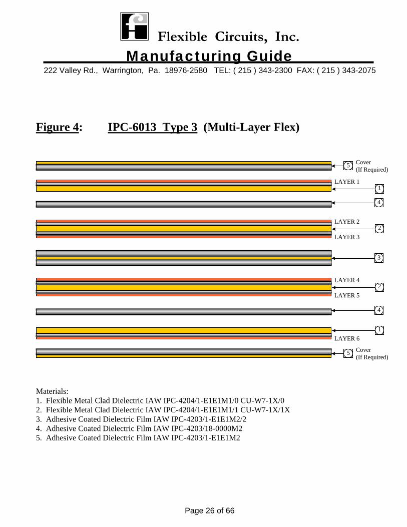
Figure 4: IPC-6013 Type 3 (Multi-Layer Flex)
LAYER 2
LAYER 32
LAYER 4
LAYER 52
3
LAYER 11
4
4
1LAYER 6
5 Cover(If Required)
5 Cover(If Required)
Materials: 1. Flexible Metal Clad Dielectric IAW IPC-4204/1-E1E1M1/0 CU-W7-1X/0 2. Flexible Metal Clad Dielectric IAW IPC-4204/1-E1E1M1/1 CU-W7-1X/1X 3. Adhesive Coated Dielectric Film IAW IPC-4203/1-E1E1M2/2 4. Adhesive Coated Dielectric Film IAW IPC-4203/18-0000M2 5. Adhesive Coated Dielectric Film IAW IPC-4203/1-E1E1M2
Flexible Circuits, Inc. Manufacturing Guide
222 Valley Rd., Warrington, Pa. 18976-2580 TEL: ( 215 ) 343-2300 FAX: ( 215 ) 343-2075
Page 27 of 66
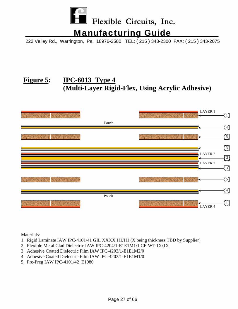
Figure 5: IPC-6013 Type 4 (Multi-Layer Rigid-Flex, Using Acrylic Adhesive)
LAYER 11
5
5
LAYER 41
LAYER 2
LAYER 3
3
2
3
4Pouch
4Pouch
Materials: 1. Rigid Laminate IAW IPC-4101/41 GIL XXXX H1/H1 (X being thickness TBD by Supplier) 2. Flexible Metal Clad Dielectric IAW IPC-4204/1-E1E1M1/1 CF-W7-1X/1X 3. Adhesive Coated Dielectric Film IAW IPC-4203/1-E1E1M2/0 4. Adhesive Coated Dielectric Film IAW IPC-4203/1-E1E1M1/0 5. Pre-Preg IAW IPC-4101/42 E1080
Flexible Circuits, Inc. Manufacturing Guide
222 Valley Rd., Warrington, Pa. 18976-2580 TEL: ( 215 ) 343-2300 FAX: ( 215 ) 343-2075
Page 28 of 66
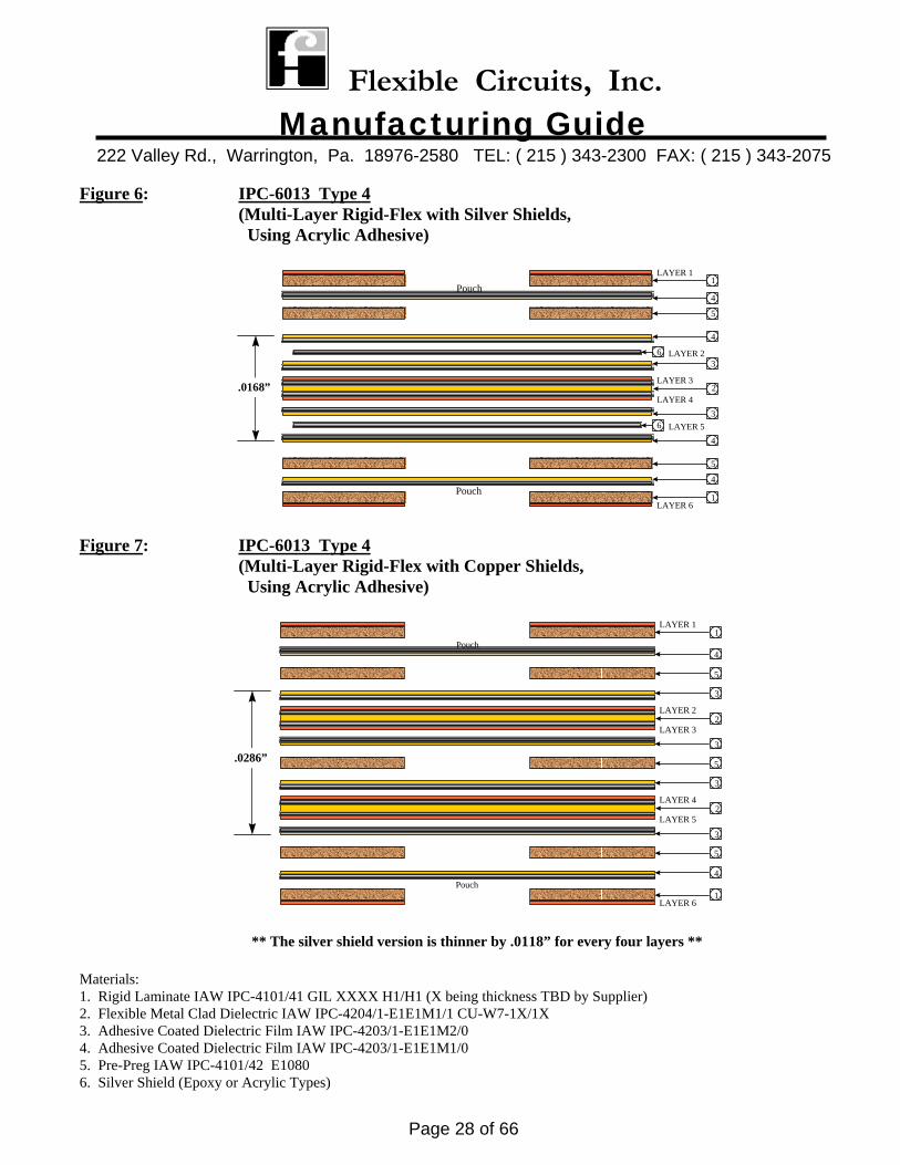
Figure 6: IPC-6013 Type 4 (Multi-Layer Rigid-Flex with Silver Shields, Using Acrylic Adhesive)
LAYER 11
5
5
LAYER 61
4
4
LAYER 3
LAYER 4
3
3
2
Pouch
Pouch
4
4
6 LAYER 2
6 LAYER 5
.0168”
Figure 7: IPC-6013 Type 4 (Multi-Layer Rigid-Flex with Copper Shields, Using Acrylic Adhesive)
LAYER 11
5
5
LAYER 61
4
4
LAYER 2
LAYER 3
3
2
Pouch
Pouch
LAYER 4
LAYER 52
3
3
5
3
.0286”
** The silver shield version is thinner by .0118” for every four layers ** Materials: 1. Rigid Laminate IAW IPC-4101/41 GIL XXXX H1/H1 (X being thickness TBD by Supplier) 2. Flexible Metal Clad Dielectric IAW IPC-4204/1-E1E1M1/1 CU-W7-1X/1X 3. Adhesive Coated Dielectric Film IAW IPC-4203/1-E1E1M2/0 4. Adhesive Coated Dielectric Film IAW IPC-4203/1-E1E1M1/0 5. Pre-Preg IAW IPC-4101/42 E1080 6. Silver Shield (Epoxy or Acrylic Types)
Flexible Circuits, Inc. Manufacturing Guide
222 Valley Rd., Warrington, Pa. 18976-2580 TEL: ( 215 ) 343-2300 FAX: ( 215 ) 343-2075
Page 29 of 66
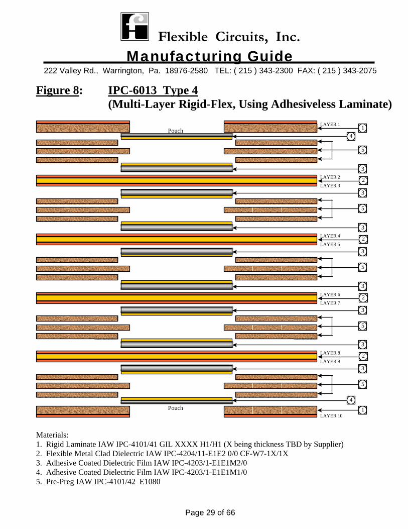
Figure 8: IPC-6013 Type 4 (Multi-Layer Rigid-Flex, Using Adhesiveless Laminate)
LAYER 1 1
LAYER 101
Pouch
LAYER 3
LAYER 2 2
3
3
5
LAYER 5
LAYER 4 2
3
3
5
5
LAYER 7
LAYER 6 2
3
3
5
4
4
LAYER 9
LAYER 8 2
3
3
5
Pouch
Materials: 1. Rigid Laminate IAW IPC-4101/41 GIL XXXX H1/H1 (X being thickness TBD by Supplier) 2. Flexible Metal Clad Dielectric IAW IPC-4204/11-E1E2 0/0 CF-W7-1X/1X 3. Adhesive Coated Dielectric Film IAW IPC-4203/1-E1E1M2/0 4. Adhesive Coated Dielectric Film IAW IPC-4203/1-E1E1M1/0 5. Pre-Preg IAW IPC-4101/42 E1080

Flexible Circuits, Inc. Manufacturing Guide
222 Valley Rd., Warrington, Pa. 18976-2580 TEL: ( 215 ) 343-2300 FAX: ( 215 ) 343-2075
Page 30 of 66
ARTWORK
Flexible Circuits, Inc. Manufacturing Guide
222 Valley Rd., Warrington, Pa. 18976-2580 TEL: ( 215 ) 343-2300 FAX: ( 215 ) 343-2075
Page 31 of 66
Artwork Guidelines for Flexible Printed Wiring Boards Artwork design is another key ingredient in determining the circuit’s performance and life expectancy. Most design software systems do not automatically design artwork for optimum flexible circuitry applications. These systems were designed for generating artwork for “rigid boards” and not for flexible circuitry. FCI highly recommends systems that can either automatically or manually add features such as “fillets”, “anchoring spurs”, “radius corners”, etc. These enhancements are MOST crucial for optimizing the performance and life expectancy of the flexible circuit. FCI has a software system that can easily add these features to most artwork software files. The format most commonly used is Gerber. These next pages will the show the recommended artwork features.
Flexible Circuits, Inc. Manufacturing Guide
222 Valley Rd., Warrington, Pa. 18976-2580 TEL: ( 215 ) 343-2300 FAX: ( 215 ) 343-2075
Page 32 of 66
Artwork Guidelines cont’d
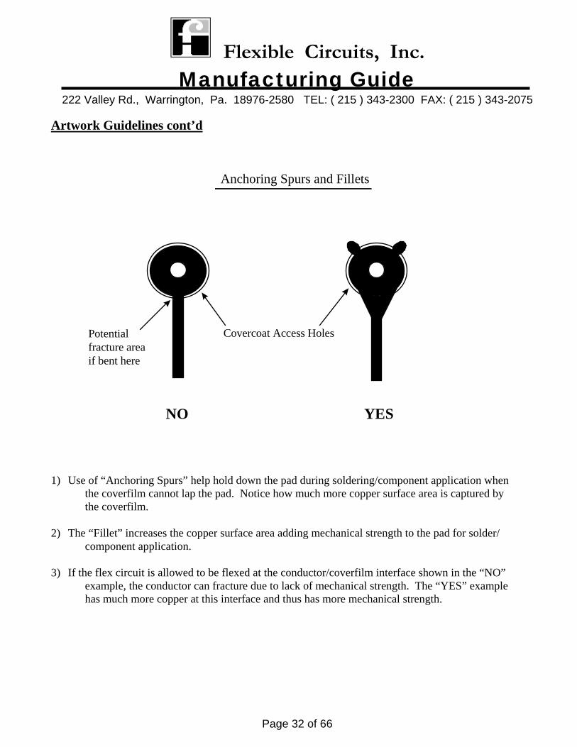
1) Use of “Anchoring Spurs” help hold down the pad during soldering/component application when the coverfilm cannot lap the pad. Notice how much more copper surface area is captured by the coverfilm. 2) The “Fillet” increases the copper surface area adding mechanical strength to the pad for solder/ component application. 3) If the flex circuit is allowed to be flexed at the conductor/coverfilm interface shown in the “NO” example, the conductor can fracture due to lack of mechanical strength. The “YES” example has much more copper at this interface and thus has more mechanical strength.
Anchoring Spurs and Fillets
YESNO
Covercoat Access HolesPotentialfracture areaif bent here
Flexible Circuits, Inc. Manufacturing Guide
222 Valley Rd., Warrington, Pa. 18976-2580 TEL: ( 215 ) 343-2300 FAX: ( 215 ) 343-2075
Page 33 of 66
Artwork Guidelines cont’d
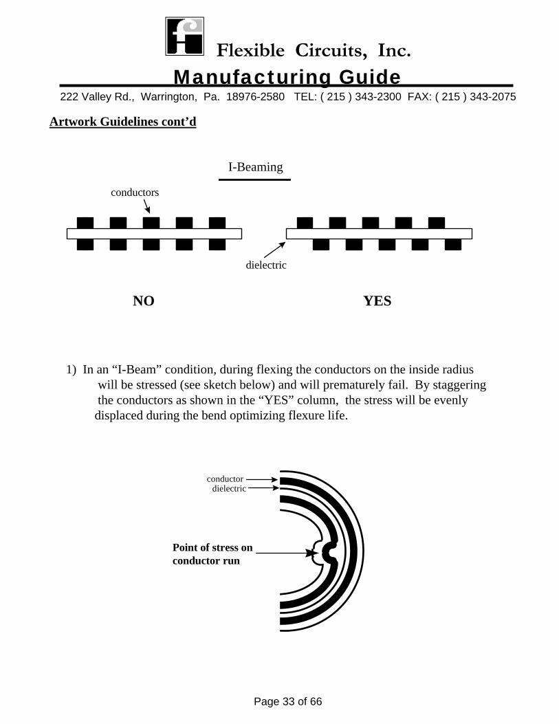
I-Beaming
1) In an “I-Beam” condition, during flexing the conductors on the inside radius will be stressed (see sketch below) and will prematurely fail. By staggering the conductors as shown in the “YES” column, the stress will be evenly displaced during the bend optimizing flexure life.
YESNO
Point of stress onconductor run
conductordielectric
conductors
dielectric
Flexible Circuits, Inc. Manufacturing Guide
222 Valley Rd., Warrington, Pa. 18976-2580 TEL: ( 215 ) 343-2300 FAX: ( 215 ) 343-2075
Page 34 of 66
Artwork Guidelines cont’d
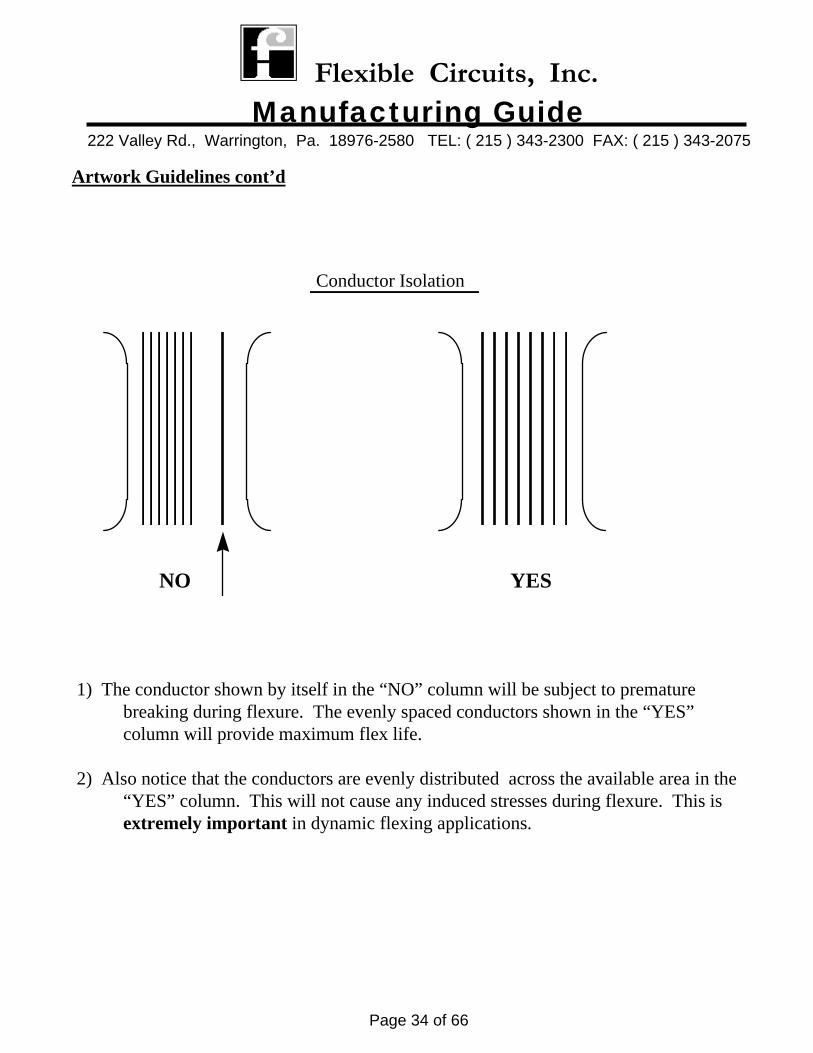
Conductor Isolation
1) The conductor shown by itself in the “NO” column will be subject to premature breaking during flexure. The evenly spaced conductors shown in the “YES” column will provide maximum flex life.
2) Also notice that the conductors are evenly distributed across the available area in the “YES” column. This will not cause any induced stresses during flexure. This is extremely important in dynamic flexing applications.
YESNO
Flexible Circuits, Inc. Manufacturing Guide
222 Valley Rd., Warrington, Pa. 18976-2580 TEL: ( 215 ) 343-2300 FAX: ( 215 ) 343-2075
Page 35 of 66
Artwork Guidelines cont’d
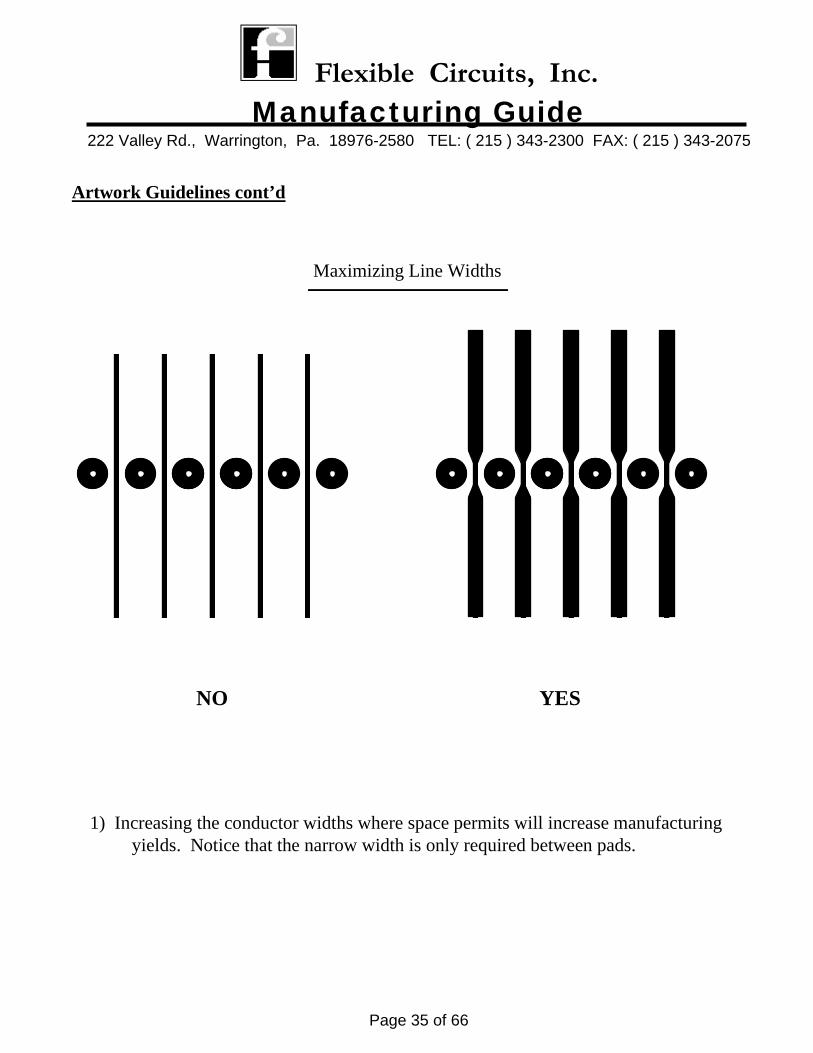
Maximizing Line Widths
1) Increasing the conductor widths where space permits will increase manufacturing yields. Notice that the narrow width is only required between pads.
NO YES
Flexible Circuits, Inc. Manufacturing Guide
222 Valley Rd., Warrington, Pa. 18976-2580 TEL: ( 215 ) 343-2300 FAX: ( 215 ) 343-2075
Page 36 of 66
Artwork Guidelines cont’d
Elongated Pads
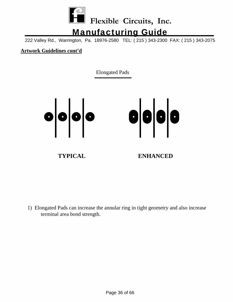
1) Elongated Pads can increase the annular ring in tight geometry and also increase terminal area bond strength.
TYPICAL ENHANCED
Flexible Circuits, Inc. Manufacturing Guide
222 Valley Rd., Warrington, Pa. 18976-2580 TEL: ( 215 ) 343-2300 FAX: ( 215 ) 343-2075
Page 37 of 66
Artwork Guidelines cont’d
Tear Stops
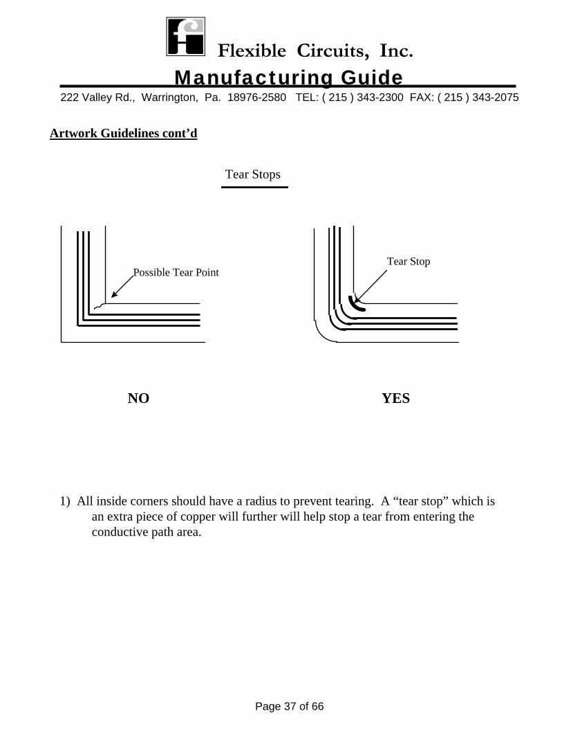
1) All inside corners should have a radius to prevent tearing. A “tear stop” which is an extra piece of copper will further will help stop a tear from entering the conductive path area.
Tear StopPossible Tear Point
NO YES
Flexible Circuits, Inc. Manufacturing Guide
222 Valley Rd., Warrington, Pa. 18976-2580 TEL: ( 215 ) 343-2300 FAX: ( 215 ) 343-2075
Page 38 of 66
Artwork Guidelines cont’d
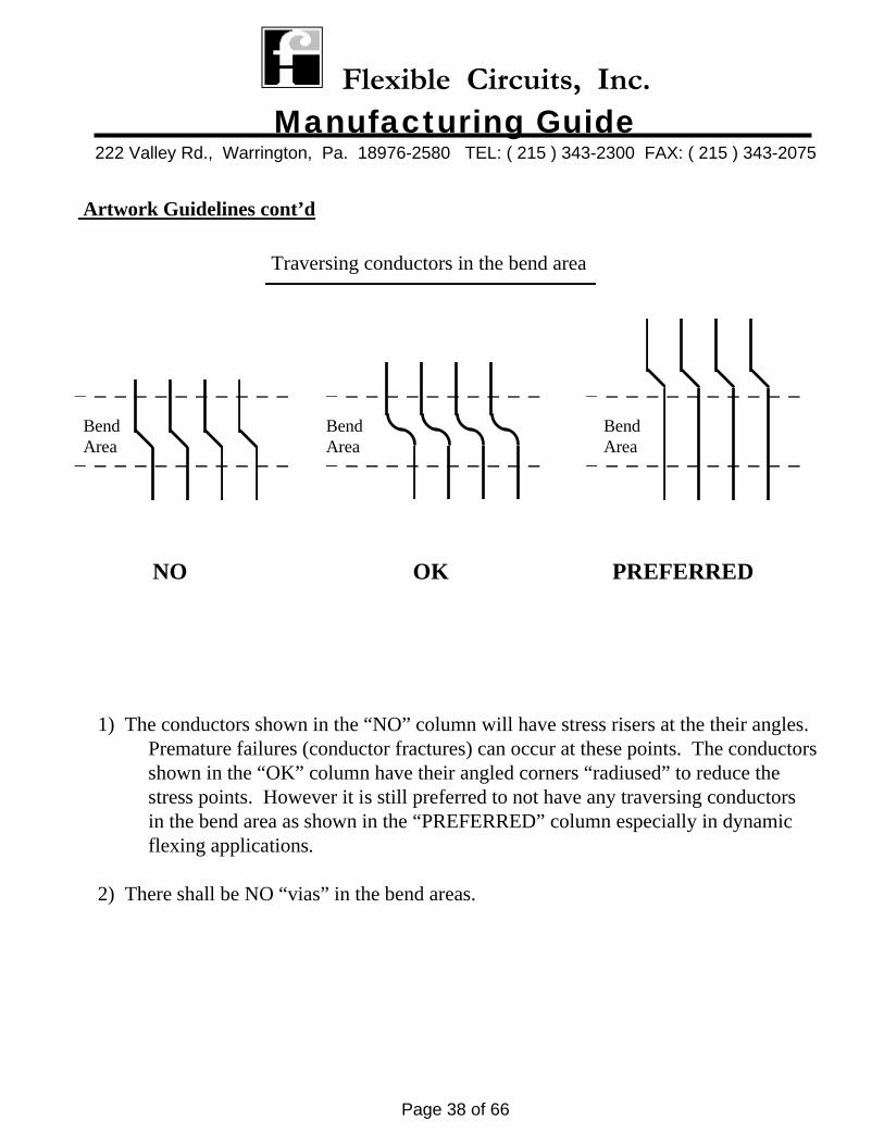
Traversing conductors in the bend area
1) The conductors shown in the “NO” column will have stress risers at the their angles. Premature failures (conductor fractures) can occur at these points. The conductors shown in the “OK” column have their angled corners “radiused” to reduce the stress points. However it is still preferred to not have any traversing conductors in the bend area as shown in the “PREFERRED” column especially in dynamic flexing applications.
2) There shall be NO “vias” in the bend areas.
PREFERREDNO
BendArea
BendArea
OK
BendArea
Flexible Circuits, Inc. Manufacturing Guide
222 Valley Rd., Warrington, Pa. 18976-2580 TEL: ( 215 ) 343-2300 FAX: ( 215 ) 343-2075
Page 39 of 66
Pad Size vs. Hole Size Calculation The area where Artwork designs fail most to allow enough processing tolerance to meet the minimum annular ring is “pad size” calculation. FCI uses the formula from MIL-STD-2118 to calculate the minimum pad size for the required hole size. The formula is as follows: Minimum Pad Size = A + 2B +2C(when required) + D A = Maximum diameter of the drilled hole for internal lands and finished hole for external Lands.
B = Minimum annular ring required C = Maximum allowance for etchback (when required) D = Standard Fabrication Allowance. This was determined by statistical survey, which
considers tooling and process variations required to fabricate boards. ** FCI will accept all Artwork down to reduced producibility **
Example A: Double Sided Circuit with .035 +/-.003 hole size Minimum Pad Size = .040 (drill size) + .010 (2 x .005 annular ring) + 0 (no etchback) + .012 (reduced producibilty factor) or = .062” Example B: Multilayer Circuit with .035 +/- .003 hole size
Minimum Pad Size = .041 (drill size) + .004 (2 x .002 annular ring) + .006 (2 x .003 max. etchback) + (Internal Layer) .012 (reduced producibility factor) or = .063”
UP TO 12 INCHES
GREATEST BOARDDIMENSION
ALLOWANCES (INCHES)
12 TO 18 INCHES
GREATER THAN18 INCHES
PREFERRED STANDARD REDUCED PRODUCIBILITY
.028
.034
.020
.024
.012
.016
DRAWING TOLERANCES MUST REFLECT BEND AND FOLD ALLOWANCES BETWEEN COMPONENT MOUNTING RIGID AREAS
STANDARD FABRICATION ALLOWANCES
Flexible Circuits, Inc. Manufacturing Guide
222 Valley Rd., Warrington, Pa. 18976-2580 TEL: ( 215 ) 343-2300 FAX: ( 215 ) 343-2075
Page 40 of 66
MISCELLANEOUS
Flexible Circuits, Inc. Manufacturing Guide
222 Valley Rd., Warrington, Pa. 18976-2580 TEL: ( 215 ) 343-2300 FAX: ( 215 ) 343-2075
Page 41 of 66
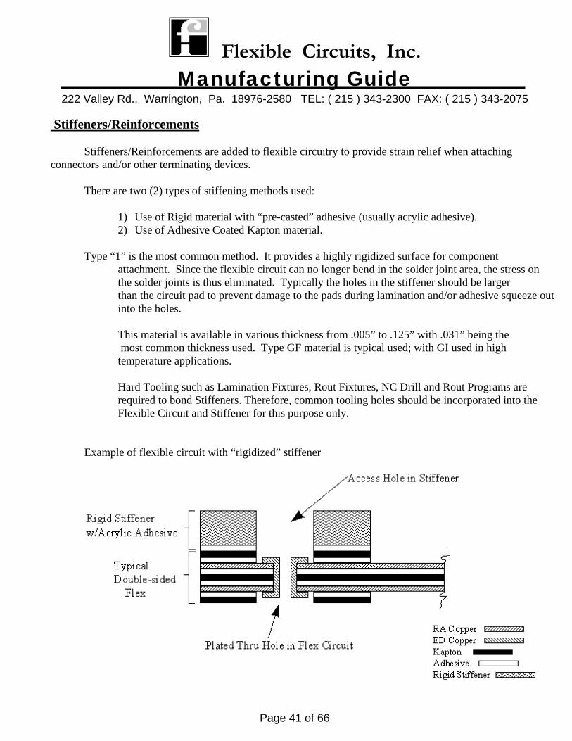
Stiffeners/Reinforcements Stiffeners/Reinforcements are added to flexible circuitry to provide strain relief when attaching connectors and/or other terminating devices.
There are two (2) types of stiffening methods used:
1) Use of Rigid material with “pre-casted” adhesive (usually acrylic adhesive). 2) Use of Adhesive Coated Kapton material.
Type “1” is the most common method. It provides a highly rigidized surface for component
attachment. Since the flexible circuit can no longer bend in the solder joint area, the stress on the solder joints is thus eliminated. Typically the holes in the stiffener should be larger than the circuit pad to prevent damage to the pads during lamination and/or adhesive squeeze out into the holes. This material is available in various thickness from .005” to .125” with .031” being the most common thickness used. Type GF material is typical used; with GI used in high temperature applications.
Hard Tooling such as Lamination Fixtures, Rout Fixtures, NC Drill and Rout Programs are required to bond Stiffeners. Therefore, common tooling holes should be incorporated into the Flexible Circuit and Stiffener for this purpose only.
Example of flexible circuit with “rigidized” stiffener
Flexible Circuits, Inc. Manufacturing Guide
222 Valley Rd., Warrington, Pa. 18976-2580 TEL: ( 215 ) 343-2300 FAX: ( 215 ) 343-2075
Page 42 of 66
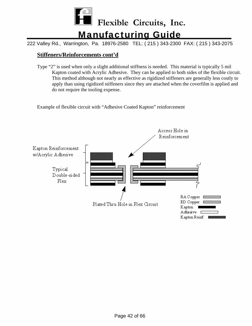
Stiffeners/Reinforcements cont’d Type “2” is used when only a slight additional stiffness is needed. This material is typically 5 mil
Kapton coated with Acrylic Adhesive. They can be applied to both sides of the flexible circuit. This method although not nearly as effective as rigidized stiffeners are generally less costly to apply than using rigidized stiffeners since they are attached when the coverfilm is applied and do not require the tooling expense.
Example of flexible circuit with “Adhesive Coated Kapton” reinforcement
Flexible Circuits, Inc. Manufacturing Guide
222 Valley Rd., Warrington, Pa. 18976-2580 TEL: ( 215 ) 343-2300 FAX: ( 215 ) 343-2075
Page 43 of 66
Desmear/Etchback
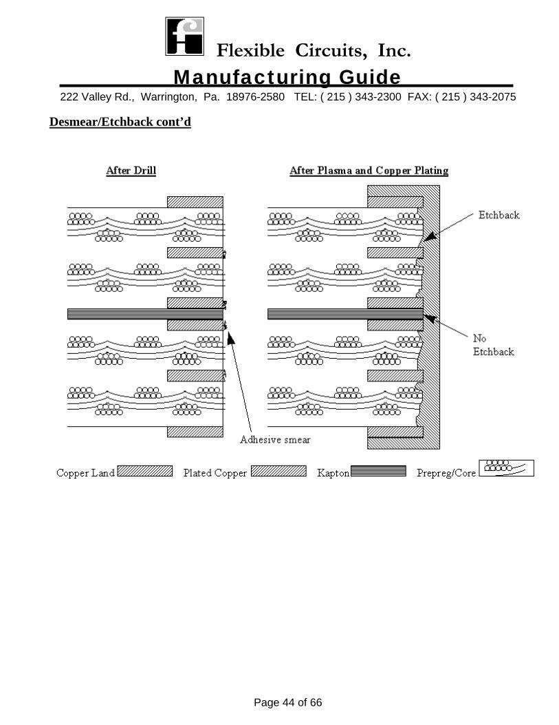
Desmear is the removal of “adhesive smear” inside the hole barrel caused by the drilling operation. Etchback is the horizontal removal of the “adhesive” material. Both of these processes are typically performed using “plasma” technology. History Prior to the development of adhesive less flex materials, etchback was necessary in multilayer rigid/flex type constructions (especially in high layer counts). These constructions employed use of acrylic adhesive in the flex materials. This resulted in excessive “z axis” expansion of the composite during thermal stressing which can cause a separation at the interface of the inner layer copper foil and the through hole plating. Etchback helped reduce this from occurring. Any similar constructions built today (generally more than 6 layers) would still require etchback.
**NOTE: If etchback is required, it must be specified on the procurement drawing** Today
With the availability of adhesive-less clad flex materials, GI type core, prepreg, and with an Engineered technique of keeping the coverfilm material out of the plated through holes, the “z axis” expansion is dramatically reduced. The harmful stress at the interface of the inner layer copper foil is eliminated, and etchback is no longer needed.
**See Next Page for Pictorial**
Flexible Circuits, Inc. Manufacturing Guide
222 Valley Rd., Warrington, Pa. 18976-2580 TEL: ( 215 ) 343-2300 FAX: ( 215 ) 343-2075
Page 44 of 66
Desmear/Etchback cont’d
Flexible Circuits, Inc. Manufacturing Guide
222 Valley Rd., Warrington, Pa. 18976-2580 TEL: ( 215 ) 343-2300 FAX: ( 215 ) 343-2075
Page 45 of 66
Dynamic Flexing Applications Materials Selection and Design are the two (2) major components to maximize flexure life. This Section will cover materials only. A later section will discuss design. There are two(2) types of dynamic flex applications:
1) Continuous back and forth bend (a rolling type action) 2) A bend over a radius where the flexing action is at the same focal point.
In the first application, FCI has found that the “Adhesive-less” Flexible Metal Clad Laminate has the longest life. In the second type application, FCI has found that the Flexible Metal Clad Laminate with “Acrylic
Adhesive” has the longest life.
There are common practices that should be employed on both applications:
1) Material construction should be balanced (copper weights, adhesive thickness, Kapton Thickness should be same from the center origin of the material.
2) 1 oz Copper performs the best. Durable enough but does not impose thickness. 3) The thickness of the materials at the bend area should be minimized. 4) Electrodeposited Copper should be avoided in bend areas. 5) Rolled Annealed Copper Foil (Type W7) should be used.
The following items should be identified on the procurement document:
1) Direction of bend 2) Degree of bend 3) Number of fold cycles 4) Diameter of mandrel 5) Points of application
Guidelines for determining minimum bend radius capability of the material
1) Single and double-sided a) Minimum bend radius to be 6 times the thickness of the materials.
2) Mulitlayer Flex a) Minimum bend radius to be 12 times the thickness of the materials.
Flexible Circuits, Inc. Manufacturing Guide
222 Valley Rd., Warrington, Pa. 18976-2580 TEL: ( 215 ) 343-2300 FAX: ( 215 ) 343-2075
Page 46 of 66
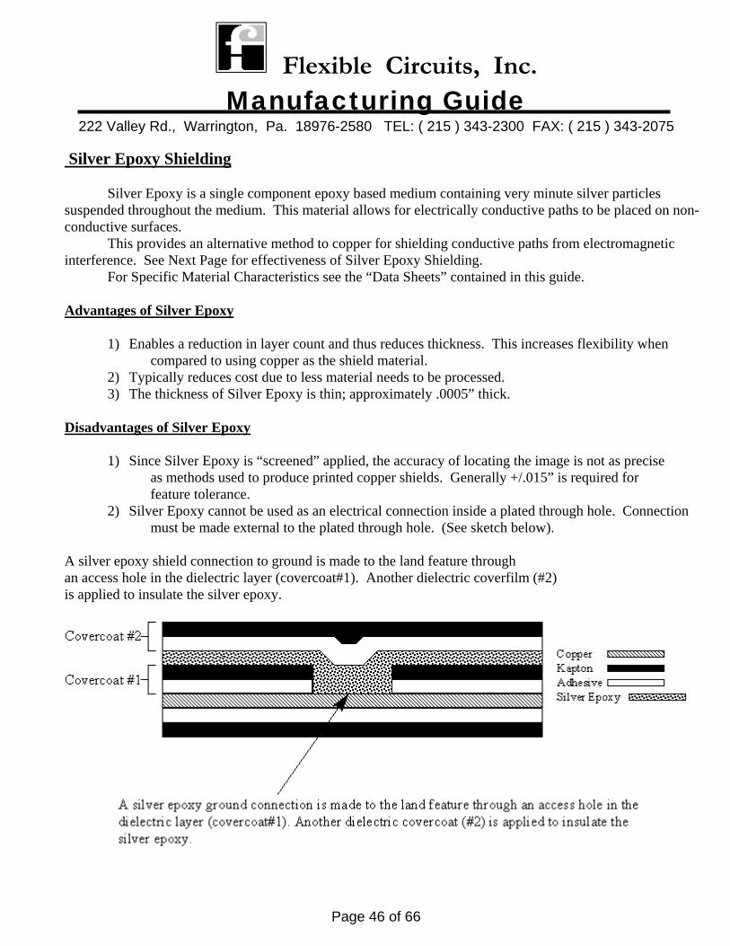
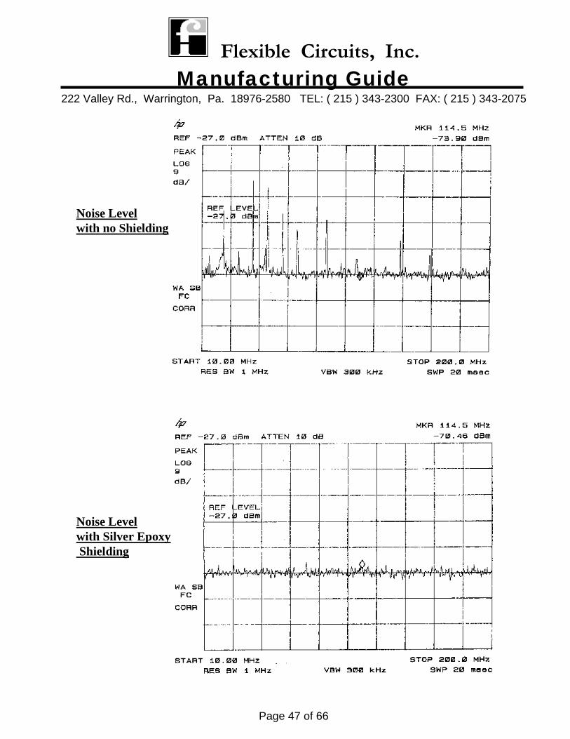
Silver Epoxy Shielding Silver Epoxy is a single component epoxy based medium containing very minute silver particles suspended throughout the medium. This material allows for electrically conductive paths to be placed on non- conductive surfaces. This provides an alternative method to copper for shielding conductive paths from electromagnetic interference. See Next Page for effectiveness of Silver Epoxy Shielding.
For Specific Material Characteristics see the “Data Sheets” contained in this guide. Advantages of Silver Epoxy
1) Enables a reduction in layer count and thus reduces thickness. This increases flexibility when compared to using copper as the shield material.
2) Typically reduces cost due to less material needs to be processed. 3) The thickness of Silver Epoxy is thin; approximately .0005” thick.
Disadvantages of Silver Epoxy
1) Since Silver Epoxy is “screened” applied, the accuracy of locating the image is not as precise as methods used to produce printed copper shields. Generally +/.015” is required for feature tolerance.
2) Silver Epoxy cannot be used as an electrical connection inside a plated through hole. Connection must be made external to the plated through hole. (See sketch below).
A silver epoxy shield connection to ground is made to the land feature through an access hole in the dielectric layer (covercoat#1). Another dielectric coverfilm (#2) is applied to insulate the silver epoxy.
Flexible Circuits, Inc. Manufacturing Guide
222 Valley Rd., Warrington, Pa. 18976-2580 TEL: ( 215 ) 343-2300 FAX: ( 215 ) 343-2075
Page 47 of 66
Noise Levelwith no Shielding
Noise Levelwith Silver Epoxy Shielding
Flexible Circuits, Inc. Manufacturing Guide
222 Valley Rd., Warrington, Pa. 18976-2580 TEL: ( 215 ) 343-2300 FAX: ( 215 ) 343-2075
Page 48 of 66
Surface Mount Applications: Material construction can play a vital role a role in two (2) key areas:
1) Does a restraining material need to be added? 2) How to maintain “co-planarity” of the flexible printed wiring board for device attachment?
Item #1 Glass reinforced Epoxy or Polyimide can be used in most surface mount applications. Typically these materials have “X” and “Y” movement of approx. 15 ppm/°C. However, a lower ppm can be achieved by increasing the “glass” content of the rigid material. Utilizing heavier glass cloth styles such as type “7628” will lower the “X” and “Y” movement down to as low as 8 ppm’s. This
should be considered as a possible alternative to using highly expensive restraining materials such as Molybdenum, or using very expensive rigid materials such as Copper-Invar-Copper or Kevlar.
Item #2 To achieve optimum co-planarity, the material construction should be balanced. The materials and their thickness should be the same from the center origin of the composite. This will help reduce possible warp and twist.
Flexible Circuits, Inc. Manufacturing Guide
222 Valley Rd., Warrington, Pa. 18976-2580 TEL: ( 215 ) 343-2300 FAX: ( 215 ) 343-2075
Page 49 of 66
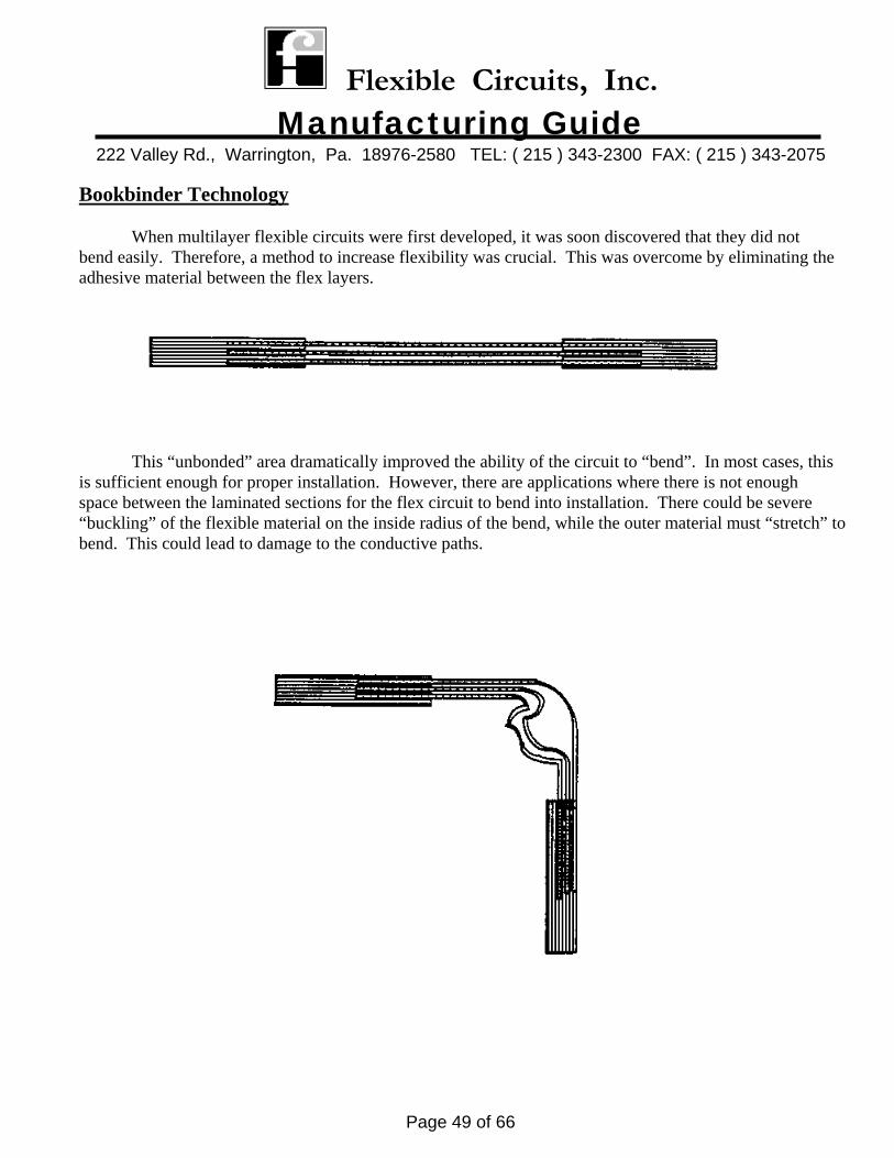
Bookbinder Technology When multilayer flexible circuits were first developed, it was soon discovered that they did not bend easily. Therefore, a method to increase flexibility was crucial. This was overcome by eliminating the adhesive material between the flex layers.
This “unbonded” area dramatically improved the ability of the circuit to “bend”. In most cases, this
is sufficient enough for proper installation. However, there are applications where there is not enough space between the laminated sections for the flex circuit to bend into installation. There could be severe “buckling” of the flexible material on the inside radius of the bend, while the outer material must “stretch” to bend. This could lead to damage to the conductive paths.
Flexible Circuits, Inc. Manufacturing Guide
222 Valley Rd., Warrington, Pa. 18976-2580 TEL: ( 215 ) 343-2300 FAX: ( 215 ) 343-2075
Page 50 of 66
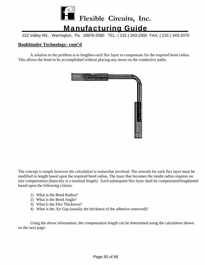
Bookbinder Technology- cont’d
A solution to the problem is to lengthen each flex layer to compensate for the required bend radius. This allows the bend to be accomplished without placing any stress on the conductive paths.
The concept is simple however the calculation is somewhat involved. The artwork for each flex layer must be modified in length based upon the required bend radius. The layer that becomes the inside radius requires no size compensation (basically is a nominal length). Each subsequent flex layer shall be compensated/lengthened based upon the following criteria:
1) What is the Bend Radius? 2) What is the Bend Angle? 3) What is the Flex Thickness? 4) What is the Air Gap (usually the thickness of the adhesive removed)?
Using the above information, the compensation length can be determined using the calculation shown on the next page:
Flexible Circuits, Inc. Manufacturing Guide
222 Valley Rd., Warrington, Pa. 18976-2580 TEL: ( 215 ) 343-2300 FAX: ( 215 ) 343-2075
Page 51 of 66
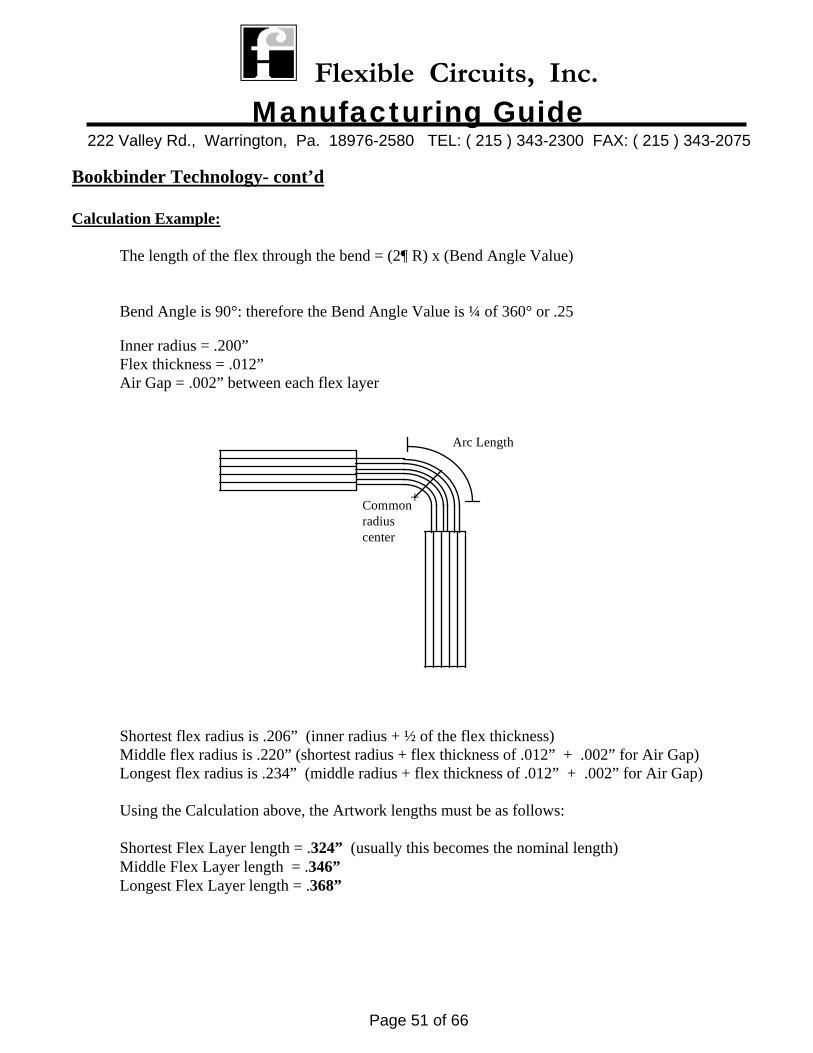
Bookbinder Technology- cont’d Calculation Example: The length of the flex through the bend = (2¶ R) x (Bend Angle Value) Bend Angle is 90°: therefore the Bend Angle Value is ¼ of 360° or .25
Inner radius = .200”
Flex thickness = .012” Air Gap = .002” between each flex layer
Shortest flex radius is .206” (inner radius + ½ of the flex thickness)
Middle flex radius is .220” (shortest radius + flex thickness of .012” + .002” for Air Gap) Longest flex radius is .234” (middle radius + flex thickness of .012” + .002” for Air Gap) Using the Calculation above, the Artwork lengths must be as follows:
Shortest Flex Layer length = .324” (usually this becomes the nominal length)
Middle Flex Layer length = .346” Longest Flex Layer length = .368”
+Commonradiuscenter
Arc Length
Flexible Circuits, Inc. Manufacturing Guide
222 Valley Rd., Warrington, Pa. 18976-2580 TEL: ( 215 ) 343-2300 FAX: ( 215 ) 343-2075
Page 52 of 66
Bookbinder Technology- cont’d Important items to consider:
1) Bookbinder manufacture is expensive. There are special tooling and processing techniques required to produce a bookbinder flexible printed wiring board due to the “hump” protruding above the panel’s surface. Some of the areas affected are tooling design, reduction in the number of circuits fitting on a panel, drilling, lamination, imaging, etc.
2) Frequently other design methods can be utilized to avoid using bookbinder processing such as lengthening the flexible bend area or reducing the thickness of the flex layers to increase
flexibility. These techniques can sometimes satisfy the installation issue. 3) Typically bookbinder yields are lower than non-bookbinder designs.
Flexible Circuits, Inc. Manufacturing Guide
222 Valley Rd., Warrington, Pa. 18976-2580 TEL: ( 215 ) 343-2300 FAX: ( 215 ) 343-2075
Page 53 of 66
Heat Sinks Heat Sinks are used to remove heat caused by the activity of components from the circuit
board. Generally they are manufactured from Aluminum or Copper and are anodized for protection and to promote a bondable surface. Thickness ranges from .020-.125”. The Materials used for attaching Heat Sinks to the Circuit Board are:
1) Acrylic Adhesive 2) No-Flow Prepreg 3) High Strength Liquid Epoxy Adhesive
Types 1 and 2 are most frequently used due to they have a controlled rate of adhesive flow,
are easily fabricated to match the Heat Sink’s pattern, and are the same materials that are used in the manufacture of the circuit board.
Hard Tooling such as Lamination Fixtures, Steel Rule Dies, NC Drill Programs, etc. may be
required to bond the Heat Sink to the circuit board. This means that common tooling holes should be incorporated into the Heat Sink and Circuit Board design.
Flexible Circuits, Inc. Manufacturing Guide
222 Valley Rd., Warrington, Pa. 18976-2580 TEL: ( 215 ) 343-2300 FAX: ( 215 ) 343-2075
Page 54 of 66
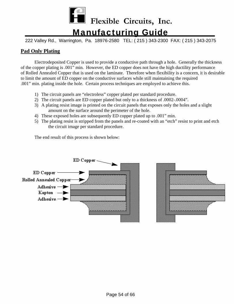
Pad Only Plating Electrodeposited Copper is used to provide a conductive path through a hole. Generally the thickness of the copper plating is .001” min. However, the ED copper does not have the high ductility performance of Rolled Annealed Copper that is used on the laminate. Therefore when flexibility is a concern, it is desirable to limit the amount of ED copper on the conductive surfaces while still maintaining the required .001” min. plating inside the hole. Certain process techniques are employed to achieve this.
1) The circuit panels are “electroless” copper plated per standard procedure. 2) The circuit panels are ED copper plated but only to a thickness of .0002-.0004”. 3) A plating resist image is printed on the circuit panels that exposes only the holes and a slight
amount on the surface around the perimeter of the hole. 4) These exposed holes are subsequently ED copper plated up to .001” min. 5) The plating resist is stripped from the panels and re-coated with an “etch” resist to print and etch
the circuit image per standard procedure. The end result of this process is shown below:
Flexible Circuits, Inc. Manufacturing Guide
222 Valley Rd., Warrington, Pa. 18976-2580 TEL: ( 215 ) 343-2300 FAX: ( 215 ) 343-2075
Page 55 of 66
Solder Mask Solder Mask is sometimes applied to “rigid/flex” circuits to insulate the external conductors. Most solder mask is applied over “bare copper. There are many types of solder masks available. The most common types are:
1) A “screenable wet film” 2) LPI (liquid photo imageable) 3) Dry Film 4) PIC (photo imageable coverlay)
Screenable Wet Film FCI uses type SR1010. Historically this method type has been the workhorse of the industry. It is an inexpensive type solder mask that meets IPC-SM-840 Class 3. It satisfies most applications but is not recommended for tight tolerance. LPI FCI uses type Taiyo PSR4000. This mask meets IPC-SM-840 Class 3. When tight tolerances are required, this mask is preferred over the screenable type. Since the image is applied photographically, very precise features and registration can be produced. This mask is also more durable the screenable type. Dry Film FCI uses type DuPont Vacrel 8000 series available in 2, 3, and 4 mil thick. This mask meets IPC-SM-840 Class 3. The demand for this product has waned in favor of the LPI types due to the cost. However, this mask is the most durable and has the same advantages of the LPI for tight tolerance application. PIC FCI uses type DuPont 1000 and 2000. This solder mask is a photo imageable covercoat that is generally applied to single and double sided circuits. It has the ability to “flex” along with the flexible circuit and not crack or peel. It is an inexpensive alternative to a Kapton coverfilm. However, it is not a permanent dielectric and therefore is not recommended for high reliability applications.
Flexible Circuits, Inc. Manufacturing Guide
222 Valley Rd., Warrington, Pa. 18976-2580 TEL: ( 215 ) 343-2300 FAX: ( 215 ) 343-2075
Page 56 of 66
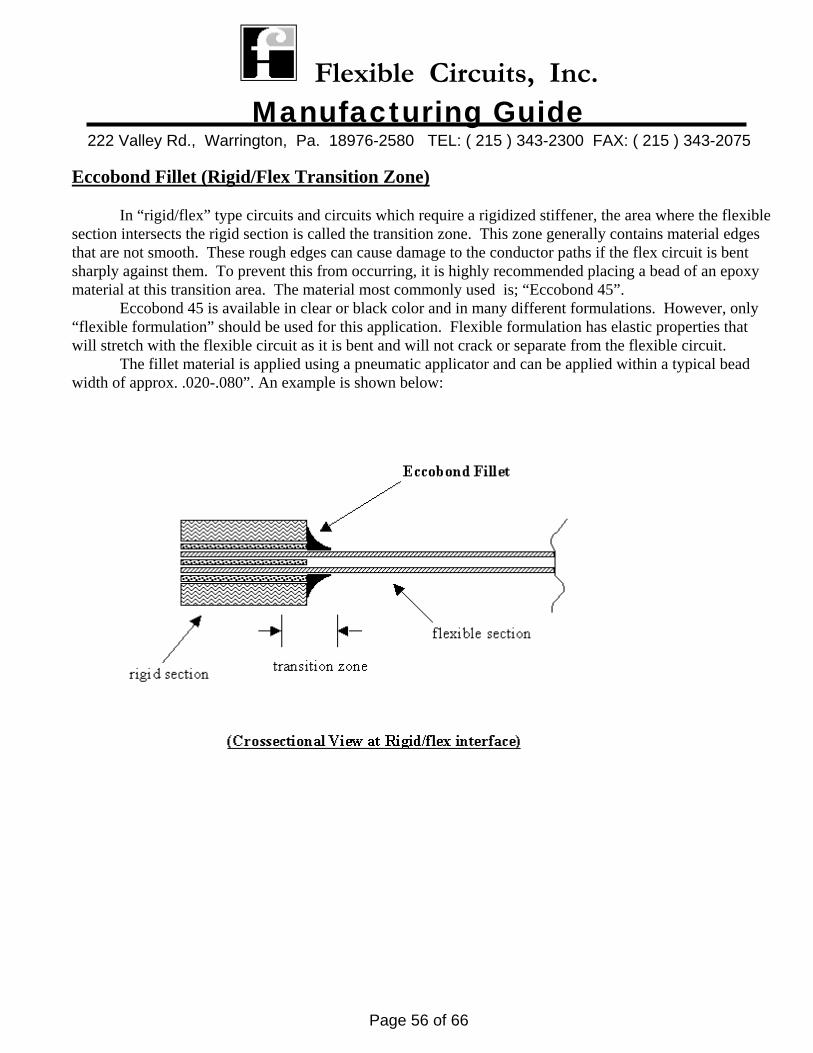
Eccobond Fillet (Rigid/Flex Transition Zone) In “rigid/flex” type circuits and circuits which require a rigidized stiffener, the area where the flexible section intersects the rigid section is called the transition zone. This zone generally contains material edges that are not smooth. These rough edges can cause damage to the conductor paths if the flex circuit is bent sharply against them. To prevent this from occurring, it is highly recommended placing a bead of an epoxy material at this transition area. The material most commonly used is; “Eccobond 45”. Eccobond 45 is available in clear or black color and in many different formulations. However, only “flexible formulation” should be used for this application. Flexible formulation has elastic properties that will stretch with the flexible circuit as it is bent and will not crack or separate from the flexible circuit. The fillet material is applied using a pneumatic applicator and can be applied within a typical bead width of approx. .020-.080”. An example is shown below:
Flexible Circuits, Inc. Manufacturing Guide
222 Valley Rd., Warrington, Pa. 18976-2580 TEL: ( 215 ) 343-2300 FAX: ( 215 ) 343-2075
Page 57 of 66
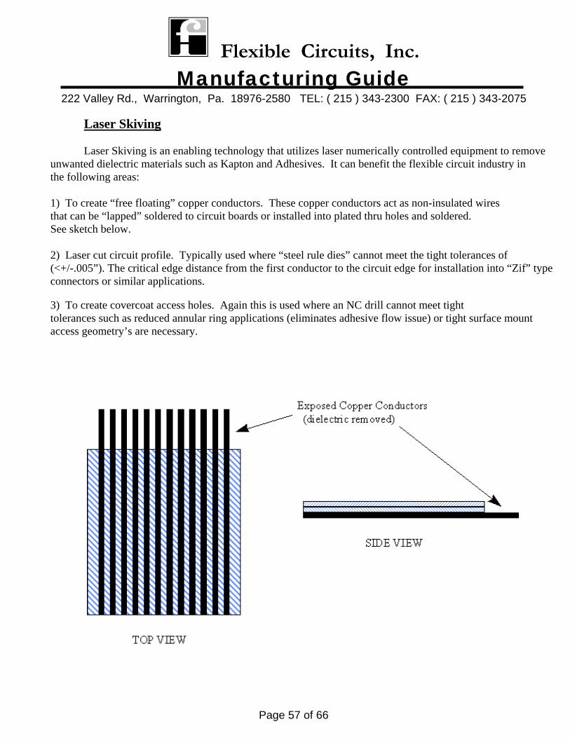
Laser Skiving Laser Skiving is an enabling technology that utilizes laser numerically controlled equipment to remove unwanted dielectric materials such as Kapton and Adhesives. It can benefit the flexible circuit industry in the following areas: 1) To create “free floating” copper conductors. These copper conductors act as non-insulated wires that can be “lapped” soldered to circuit boards or installed into plated thru holes and soldered. See sketch below. 2) Laser cut circuit profile. Typically used where “steel rule dies” cannot meet the tight tolerances of (<+/-.005”). The critical edge distance from the first conductor to the circuit edge for installation into “Zif” type connectors or similar applications. 3) To create covercoat access holes. Again this is used where an NC drill cannot meet tight tolerances such as reduced annular ring applications (eliminates adhesive flow issue) or tight surface mount access geometry’s are necessary.

Flexible Circuits, Inc. Manufacturing Guide
222 Valley Rd., Warrington, Pa. 18976-2580 TEL: ( 215 ) 343-2300 FAX: ( 215 ) 343-2075
Page 58 of 66
DATA SHEETS
Flexible Circuits, Inc. Manufacturing Guide
222 Valley Rd., Warrington, Pa. 18976-2580 TEL: ( 215 ) 343-2300 FAX: ( 215 ) 343-2075
Page 59 of 66
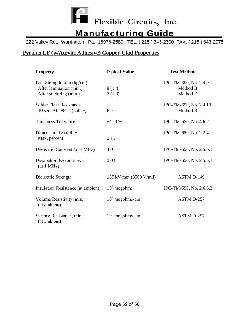
Pyralux LF (w/Acrylic Adhesive) Copper-Clad Properties
Property Typical Value Test Method Peel Strength lb/in (kg/cm) IPC-TM-650, No. 2.4.9 After lamination (min.) 8 (1.4) Method B After soldering (min.) 7 (1.3) Method D Solder Float Resistance IPC-TM-650, No. 2.4.13 10 sec. At 288°C (550°F) Pass Method B Thickness Tolerance +/- 10% IPC-TM-650, No. 4.6.2 Dimensional Stability IPC-TM-650, No. 2.2.4 Max. percent 0.15 Dielectric Constant (at 1 MHz) 4.0 IPC-TM-650, No. 2.5.5.3 Dissipation Factor, max. 0.03 IPC-TM-650, No. 2.5.5.3 (at 1 MHz) Dielectric Strength 137 kV/mm (3500 V/mil) ASTM D-149 Insulation Resistance (at ambient) 107 megohms IPC-TM-650, No. 2.6.3.2 Volume Resistivity, min. 107 megohms-cm ASTM D-257 (at ambient) Surface Resistance, min. 108 megohms-cm ASTM D-257 (at ambient)
Flexible Circuits, Inc. Manufacturing Guide
222 Valley Rd., Warrington, Pa. 18976-2580 TEL: ( 215 ) 343-2300 FAX: ( 215 ) 343-2075
Page 60 of 66
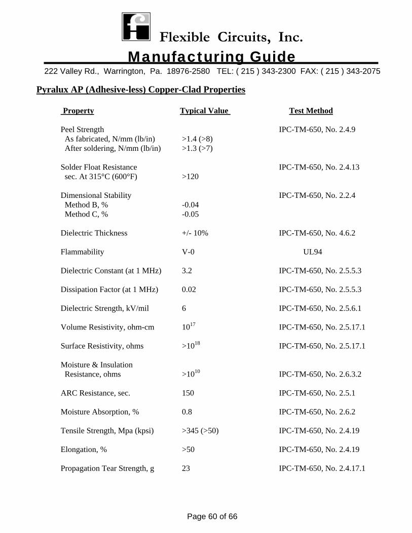
Pyralux AP (Adhesive-less) Copper-Clad Properties
Property Typical Value Test Method Peel Strength IPC-TM-650, No. 2.4.9 As fabricated, N/mm (lb/in) >1.4 (>8) After soldering, N/mm (lb/in) >1.3 (>7) Solder Float Resistance IPC-TM-650, No. 2.4.13 sec. At 315°C (600°F) >120 Dimensional Stability IPC-TM-650, No. 2.2.4 Method B, % -0.04 Method C, % -0.05 Dielectric Thickness +/- 10% IPC-TM-650, No. 4.6.2 Flammability V-0 UL94 Dielectric Constant (at 1 MHz) 3.2 IPC-TM-650, No. 2.5.5.3 Dissipation Factor (at 1 MHz) 0.02 IPC-TM-650, No. 2.5.5.3 Dielectric Strength, kV/mil 6 IPC-TM-650, No. 2.5.6.1 Volume Resistivity, ohm-cm 1017 IPC-TM-650, No. 2.5.17.1 Surface Resistivity, ohms >1018 IPC-TM-650, No. 2.5.17.1 Moisture & Insulation Resistance, ohms >1010 IPC-TM-650, No. 2.6.3.2 ARC Resistance, sec. 150 IPC-TM-650, No. 2.5.1 Moisture Absorption, % 0.8 IPC-TM-650, No. 2.6.2 Tensile Strength, Mpa (kpsi) >345 (>50) IPC-TM-650, No. 2.4.19 Elongation, % >50 IPC-TM-650, No. 2.4.19 Propagation Tear Strength, g 23 IPC-TM-650, No. 2.4.17.1
Flexible Circuits, Inc. Manufacturing Guide
222 Valley Rd., Warrington, Pa. 18976-2580 TEL: ( 215 ) 343-2300 FAX: ( 215 ) 343-2075
Page 61 of 66
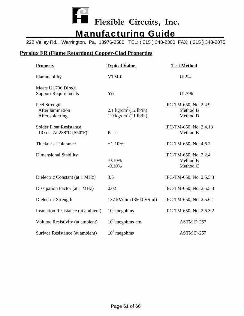
Pyralux FR (Flame Retardant) Copper-Clad Properties
Property Typical Value Test Method Flammability VTM-0 UL94 Meets UL796 Direct Support Requirements Yes UL796 Peel Strength IPC-TM-650, No. 2.4.9 After lamination 2.1 kg/cm2 (12 lb/in) Method B After soldering 1.9 kg/cm2 (11 lb/in) Method D Solder Float Resistance IPC-TM-650, No. 2.4.13 10 sec. At 288°C (550°F) Pass Method B Thickness Tolerance +/- 10% IPC-TM-650, No. 4.6.2 Dimensional Stability IPC-TM-650, No. 2.2.4 -0.10% Method B -0.10% Method C Dielectric Constant (at 1 MHz) 3.5 IPC-TM-650, No. 2.5.5.3 Dissipation Factor (at 1 MHz) 0.02 IPC-TM-650, No. 2.5.5.3 Dielectric Strength 137 kV/mm (3500 V/mil) IPC-TM-650, No. 2.5.6.1 Insulation Resistance (at ambient) 106 megohms IPC-TM-650, No. 2.6.3.2 Volume Resistivity (at ambient) 109 megohms-cm ASTM D-257 Surface Resistance (at ambient) 107 megohms ASTM D-257
Flexible Circuits, Inc. Manufacturing Guide
222 Valley Rd., Warrington, Pa. 18976-2580 TEL: ( 215 ) 343-2300 FAX: ( 215 ) 343-2075
Page 62 of 66
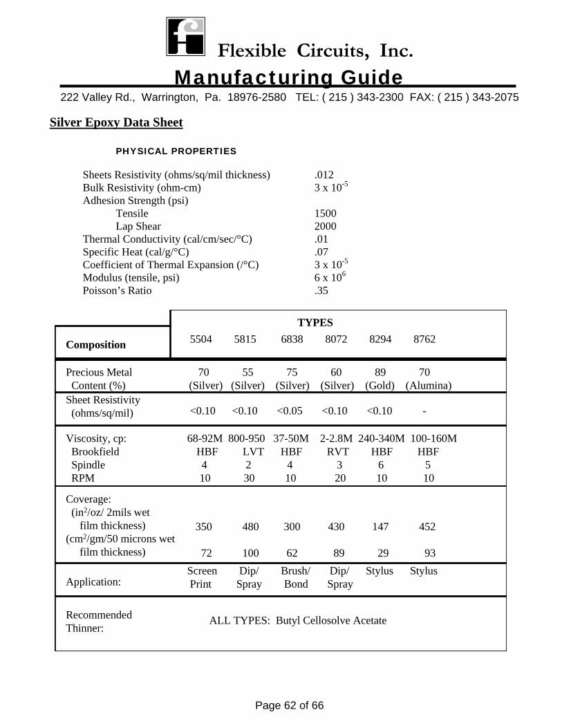
Silver Epoxy Data Sheet PHYSICAL PROPERTIES
Sheets Resistivity (ohms/sq/mil thickness) .012 Bulk Resistivity (ohm-cm) 3 x 10⁻⁵ Adhesion Strength (psi) Tensile 1500 Lap Shear 2000 Thermal Conductivity (cal/cm/sec/°C) .01 Specific Heat (cal/g/°C) .07
Coefficient of Thermal Expansion (/°C) 3 x 10⁻⁵
Modulus (tensile, psi) 6 x 10⁶
Poisson’s Ratio .35
Precious Metal 70 55 75 60 89 70 Content (%) (Silver) (Silver) (Silver) (Silver) (Gold) (Alumina) Sheet Resistivity (ohms/sq/mil) <0.10 <0.10 <0.05 <0.10 <0.10 -
Viscosity, cp: 68-92M 800-950 37-50M 2-2.8M 240-340M 100-160M Brookfield HBF LVT HBF RVT HBF HBF Spindle 4 2 4 3 6 5 RPM 10 30 10 20 10 10
Coverage: (in2/oz/ 2mils wet film thickness)(cm2/gm/50 microns wet film thickness)
350 480 300 430 147 452
72 100 62 89 29 93
Application:Screen Dip/ Brush/ Dip/ Stylus Stylus Print Spray Bond Spray
RecommendedThinner:
ALL TYPES: Butyl Cellosolve Acetate
Composition
TYPES 5504 5815 6838 8072 8294 8762
Flexible Circuits, Inc. Manufacturing Guide
222 Valley Rd., Warrington, Pa. 18976-2580 TEL: ( 215 ) 343-2300 FAX: ( 215 ) 343-2075
Page 63 of 66
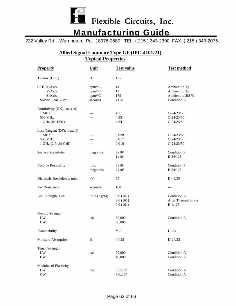
Allied Signal Laminate Type GF (IPC-4101/21)Typical Properties
Property Unit Test value Test method
Tg min. (DSC) °C 135
CTE X-Axis ppm/°C 14 Ambient to Tg Y-Axis ppm/°C 13 Ambient to Tg Z-Axis ppm/°C 175 Ambient to 288°C Solder Float, 288°C seconds >120 Condition A
Permittivity (DK), max. @ 1 MHz --- 4.7 C-24/23/50 500 MHz --- 4.35 C-24/23/50 1 GHz (HP4291) --- 4.34 C-24/23/50
Loss Tangent (DF), max. @ 1 MHz --- 0.020 C-24/23/50 500 MHz --- 0.017 C-24/23/50 1 GHz (2 Fluid Cell) --- 0.016 C-24/23/50
Surface Resistivity megohms 2x10⁵ Condition F1x108 E-24/125
Volume Resistivity min. 8x10⁷ Condition Fmegohms 2x10⁷ E-24/125
Dielectric Breakdown, min. kV 55 D-48/50
Arc Resistance seconds 100 ---
Peel Strength, 1 oz. lb/in (Kg/M) 9.0 (161) Condition A9.0 (161) After Thermal Stress9.0 (161) E-1/125
Flexure Strength LW psi 80,000 Condition A CW 60,000
Flammability --- V-0 UL94
Moisture Absorption % <0.25 D-24/23
Tensil Strength LW psi 50,000 Condition A CW 40,000 Condition A
Modulus of Elasticity LW psi 3.5x10⁶ Condition A CW 3.0x10⁶ Condition A
Flexible Circuits, Inc. Manufacturing Guide
222 Valley Rd., Warrington, Pa. 18976-2580 TEL: ( 215 ) 343-2300 FAX: ( 215 ) 343-2075
Page 64 of 66
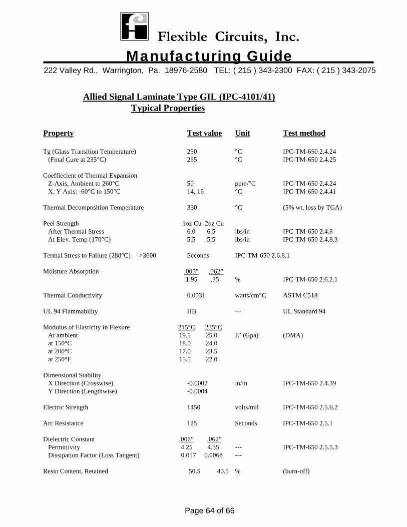
Allied Signal Laminate Type GIL (IPC-4101/41)Typical Properties
Property Test value Unit Test method
Tg (Glass Transition Temperature) 250 °C IPC-TM-650 2.4.24 (Final Cure at 235°C) 265 °C IPC-TM-650 2.4.25
Coeffiecient of Thermal Expansion Z-Axis, Ambient to 260°C 50 ppm/°C IPC-TM-650 2.4.24 X, Y Axis: -60°C to 150°C 14, 16 °C IPC-TM-650 2.4.41
Thermal Decomposition Temperature 330 °C (5% wt, loss by TGA)
Peel Strength 1oz Cu 2oz Cu After Thermal Stress 6.0 6.5 lbs/in IPC-TM-650 2.4.8 At Elev. Temp (170°C) 5.5 5.5 lbs/in IPC-TM-650 2.4.8.3
Termal Stress to Failure (288°C) >3600 Seconds IPC-TM-650 2.6.8.1
Moisture Absorption .005” .062” 1.95 .35 % IPC-TM-650 2.6.2.1
Thermal Conductivity 0.0031 watts/cm°C ASTM C518
UL 94 Flammability HB --- UL Standard 94
Modulus of Elasticity in Flexure 215°C 235°C At ambient 19.5 25.0 E’ (Gpa) (DMA) at 150°C 18.0 24.0 at 200°C 17.0 23.5 at 250°F 15.5 22.0
Dimensional Stability X Direction (Crosswise) -0.0002 in/in IPC-TM-650 2.4.39 Y Direction (Lengthwise) -0.0004
Electric Strength 1450 volts/mil IPC-TM-650 2.5.6.2
Arc Resistance 125 Seconds IPC-TM-650 2.5.1
Dielectric Constant .006” .062” Permittivity 4.25 4.35 --- IPC-TM-650 2.5.5.3 Dissipation Factor (Loss Tangent) 0.017 0.0068 ---
Resin Content, Retained 50.5 40.5 % (burn-off)
Flexible Circuits, Inc. Manufacturing Guide
222 Valley Rd., Warrington, Pa. 18976-2580 TEL: ( 215 ) 343-2300 FAX: ( 215 ) 343-2075
Page 65 of 66
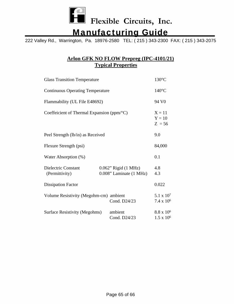
Arlon GFK NO FLOW Prepreg (IPC-4101/21)Typical Properties
Glass Transition Temperature 130°C
Continuous Operating Temperature 140°C
Flammability (UL File E48692) 94 V0
Coeffeicient of Thermal Expansion (ppm/°C) X = 11Y = 10Z = 56
Peel Strength (lb/in) as Received 9.0
Flexure Strength (psi) 84,000
Water Absorption (%) 0.1
Dielectric Constant 0.062” Rigid (1 MHz) 4.8 (Permittivity) 0.008” Laminate (1 MHz) 4.3
Dissipation Factor 0.022
Volume Resistivity (Megohm-cm) ambient 5.1 x 10⁷
Cond. D24/23 7.4 x 10⁶
Surface Resistivity (Megohms) ambient 8.8 x 10⁶
Cond. D24/23 1.5 x 10⁶
Flexible Circuits, Inc. Manufacturing Guide
222 Valley Rd., Warrington, Pa. 18976-2580 TEL: ( 215 ) 343-2300 FAX: ( 215 ) 343-2075
Page 66 of 66
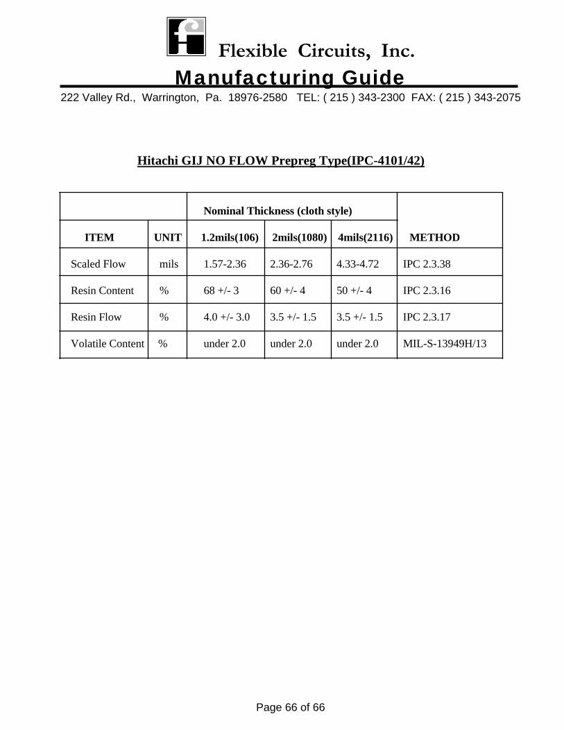
Nominal Thickness (cloth style)
ITEM UNIT 1.2mils(106) 2mils(1080) 4mils(2116) METHOD
Scaled Flow mils 1.57-2.36 2.36-2.76 4.33-4.72 IPC 2.3.38
Resin Content % 68 +/- 3 60 +/- 4 50 +/- 4 IPC 2.3.16
Resin Flow % 4.0 +/- 3.0 3.5 +/- 1.5 3.5 +/- 1.5 IPC 2.3.17
Volatile Content % under 2.0 under 2.0 under 2.0 MIL-S-13949H/13
Hitachi GIJ NO FLOW Prepreg Type(IPC-4101/42)