flexinivo fn 6 - uwt gmbh - füllstandsmessung · manual motor operation 10----- commissioning,...
TRANSCRIPT
Height adjustable level limit switch
Technical information / Instruction manual
page
Page
Function/ Dimensions 2
-------------------------------------------------------------------------------------------------------
Technical data 3
-------------------------------------------------------------------------------------------------------
Electrical connection, switching logic 4
-------------------------------------------------------------------------------------------------------
Measurement procedure 6
-------------------------------------------------------------------------------------------------------
Manual motor operation 10
-------------------------------------------------------------------------------------------------------
Commissioning, mounting, safety instructions 11
Subject to technical change and price change. We assume no liability for typing errors.
All dimensions in mm (inches). Different variations to those specified are possible.Please contact our technical consultants.
Table of contents
Flexinivo® FN 6 1
2
3
4
5
6
7
8
9
10
11
12FN 6 gi010417 1

Height adjustable level limit switch
Technical information / Instruction manual
page
Function / Dimensions
The unit can be used to measure the presence or absence of bulk material on a variable level. It is designed to be connected to a PLC, which is not part of the delivery.
Measurement principle:
A motor drives the sensor down to a desired level. An incremental or analogue encoder states the height of the sensor. When the bulk
material reaches the sensor, an output signal is actuated.
Sensor at „upper stop position“
Temperature-protection cover
Flexinivo® FN 61
2
3
4
5
6
7
8
9
10
11
12FN 6gi0104172

Height adjustable level limit switch
Technical information / Instruction manual
page
Mechanical data
Housing: Aluminium RAL 5010 gentian blue
Enclosure: IP66 to EN 60529
Process connection: Flange similar to DN100 PN16 Aluminium, black
Overall weight: approx. 17 kg Material in process: Ribbon cable: PVC, high resistance Vibrating fork: 1.4404/ 316L Vibrating fork cover: PVC
Deviation of vertical mounting: max. 2° out of the vertical
Pressure connection: Quick couppling including opposite part, for hose diameter 9 mm; max. operation pressure: 0.2 bar
Operating conditions
Incremental encoder: Resolution: 1 pulse per mm sensor movement Overall accuracy of measurement ca. 5 mm
Analogue 4-20 mA encoder: Resolution: 12 bit over 4,500 mm sensor movement Overall accuracy of measurement ca. 10 mm
Accuracy of sensor: Vibrating fork ca. 5 .. 20 mm (depending on the application and the bulk material)
Measuring range: 620 .. max. 5,120 mm (see drawing) Sensor speed (motor): Motor fast (up and downwards): ca. 80 - 180 mm/s
Motor slow (downwards): ca. 20 - 40 mm/s
Process pressure: -0.3 .. +0.3 bar
Process and ambient 0°C .. 60°Ctemperature: -20°C .. 60°C with optional temperature-protection cover
Technical data
Electrical data
Supply voltage: 230 V 50 - 60 Hz or 115 V 50 - 60 Hz both voltages +10%/ -15%
Installed load: 130 VA (incl. heating)
Connection terminal: max. 2.5 mm²
Cable entry: 2x M25 x 1.5 + 1 closing element for cable diameter 9 - 14 mm 3x NPT 1/2“ conduit connection 3x NPT 3/4“ conduit connection
Incremental encoder: Power supply: 10 - 30 V DC, max. 70 mA Pulse output: A, B, N push-pull, max. 40 mA load H-Level: > Supply voltage –2.5 V L-Level: < 2.5 V Cable length: max. 100 m
Analogue 4-20 mA encoder: Power supply: 17 - 30 V DC, max. 50 mA 4-20 mA output, active Cable length: max. 50 m
Signal outputs: „Vibrating fork signal" and "Vibrating fork in upper stop position“: Floating relais contact max. 250 V AC, 2 A, 500 VA
Control Inputs: “Motor up”, “Motor down” and “Motor fast/ slow”: Optocoupler 20 - 30 V DC, max. 10 mA each
Protection class: I
Heating: Included, thermostat controlled
Flexinivo® FN 6 1
2
3
4
5
6
7
8
9
10
11
12FN 6 gi010417 3

Height adjustable level limit switch
Technical information / Instruction manual
page
Electrical connection / Switching logic
Inte
rnal
co
nnec
tion
Hea
ting fast slow
down up
Mot
or
fast
Mot
or
slow
Mot
or
up/
dow
n
Incrementalencoder
0V +24 V (20 .. 30 V)Motor control input
from PLC
Power supply230 V or 115 V, obtain supply voltage on type plate
Powersupply
Pulseoutput
use shielded cable
Output Output
Vib
ratin
g fo
rksi
gna
l
Vib
ratin
g fo
rk in
„u
pp
er s
top
po
sitio
n“
0 V
+10
.. 30
V
out A
out B
out N
Shi
eld
Pulse output diagram:
Shown when sensor moves upwards
When rotation of the incremental encoder changes direction the signal of A and B is inverted.
Switching logic:Vibrating fork signal
Switching logic:Vibrating fork in„upper stop position“
Incremental encoder
Flexinivo® FN 61
2
3
4
5
6
7
8
9
10
11
12FN 6gi0104174
Height adjustable level limit switch
Technical information / Instruction manual
page
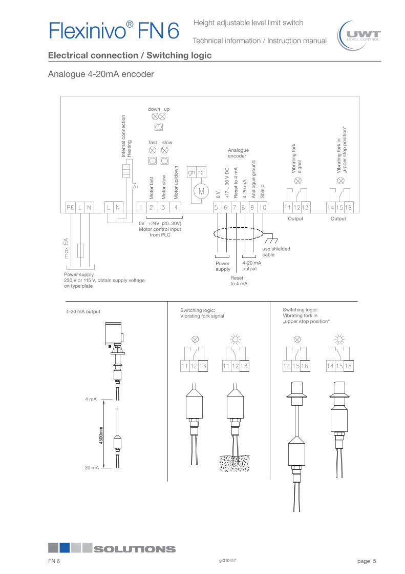
Electrical connection / Switching logic
Analogue 4-20mA encoder
Inte
rnal
co
nnec
tion
Hea
ting fast slow
down up
Mot
or
fast
Mot
or
slow
Mot
or
up/d
own
Analogueencoder
0V +24V (20..30V)Motor control input
from PLC
Power supply230 V or 115 V, obtain supply voltage on type plate
Powersupply
4-20 mAoutput
use shielded cable
Output Output
Vib
ratin
g fo
rksi
gna
l
Vib
ratin
g fo
rk in
„u
pp
er s
top
po
sitio
n“
0 V
+17
.. 30
V D
C
Res
et t
o 4
mA
4-20
mA
Ana
log
ue g
roun
d
Shi
eld
4-20 mA output Switching logic:Vibrating fork signal
Switching logic:Vibrating fork in„upper stop position“
Resetto 4 mA
Flexinivo® FN 6 1
2
3
4
5
6
7
8
9
10
11
12FN 6 gi010417 5
4 mA
20 mA

Height adjustable level limit switch
Technical information / Instruction manual
page
Measurement procedure - Incremental encoder
down/ up
fast/ slow
Vibrating fork in „upper stop position“
Terminals and diodes on pcb
Vibration forksignal
upper stopposition
0V +24 V (20 .. 30 V)
Motor control inputs
Incremental encoder output
Vibrating fork driving downwards first fast mode and short before measuring point slow mode to bring vibrating fork precise to the desired level
Fast mode
Slow mode
ATTENTION: To avoid damaging the unit while driving down-wards, ensure that the vibrating fork stops at max. 4,500 mm.
Vibrating fork stays at the measuring level, material can start to flow into the batch containerOpen valve
Flexinivo® FN 61
2
3
4
5
6
7
8
9
10
11
12FN 6gi0104176
1.
2.
3.
Height adjustable level limit switch
Technical information / Instruction manual
page
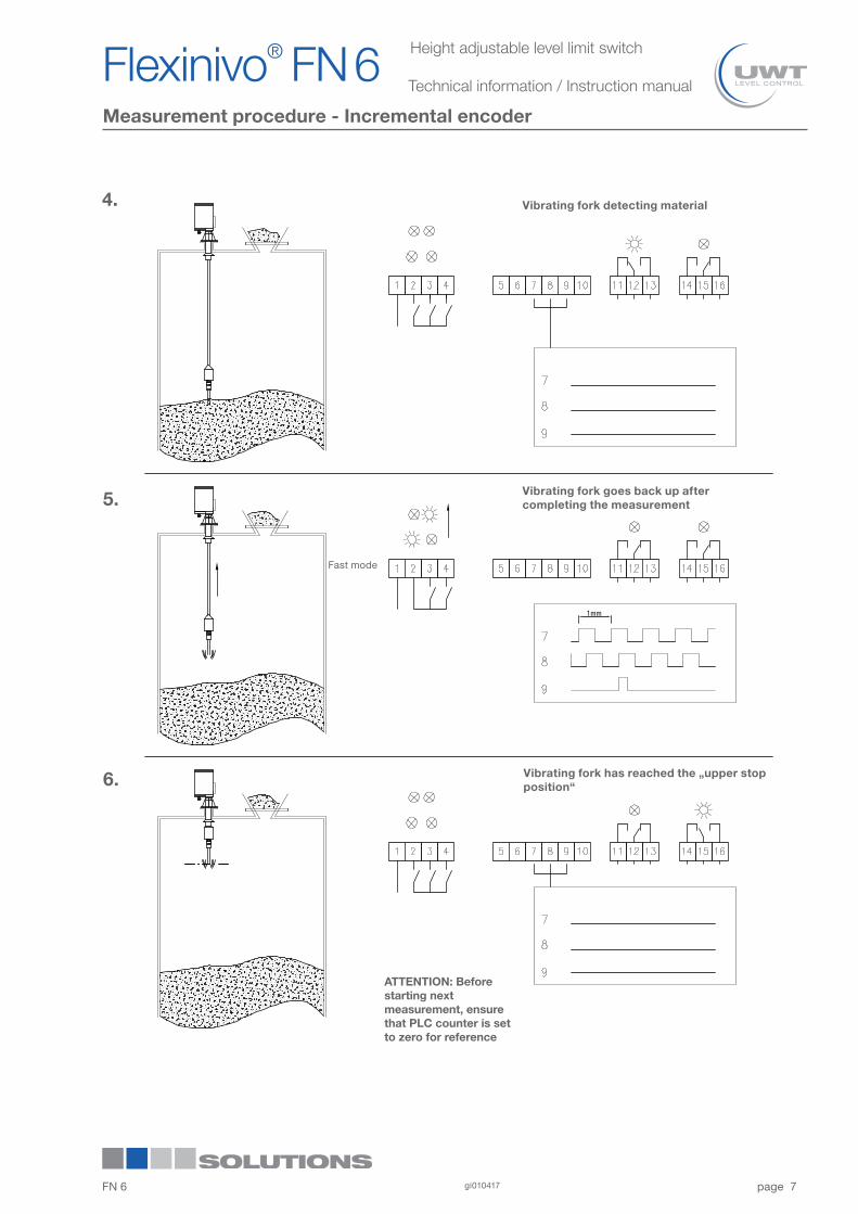
Measurement procedure - Incremental encoder
Vibrating fork detecting material
Vibrating fork goes back up after completing the measurement
Fast mode
Vibrating fork has reached the „upper stop position“
ATTENTION: Before starting next measurement, ensure that PLC counter is set to zero for reference
Flexinivo® FN 6 1
2
3
4
5
6
7
8
9
10
11
12FN 6 gi010417 7
4.
5.
6.
Height adjustable level limit switch
Technical information / Instruction manual
page
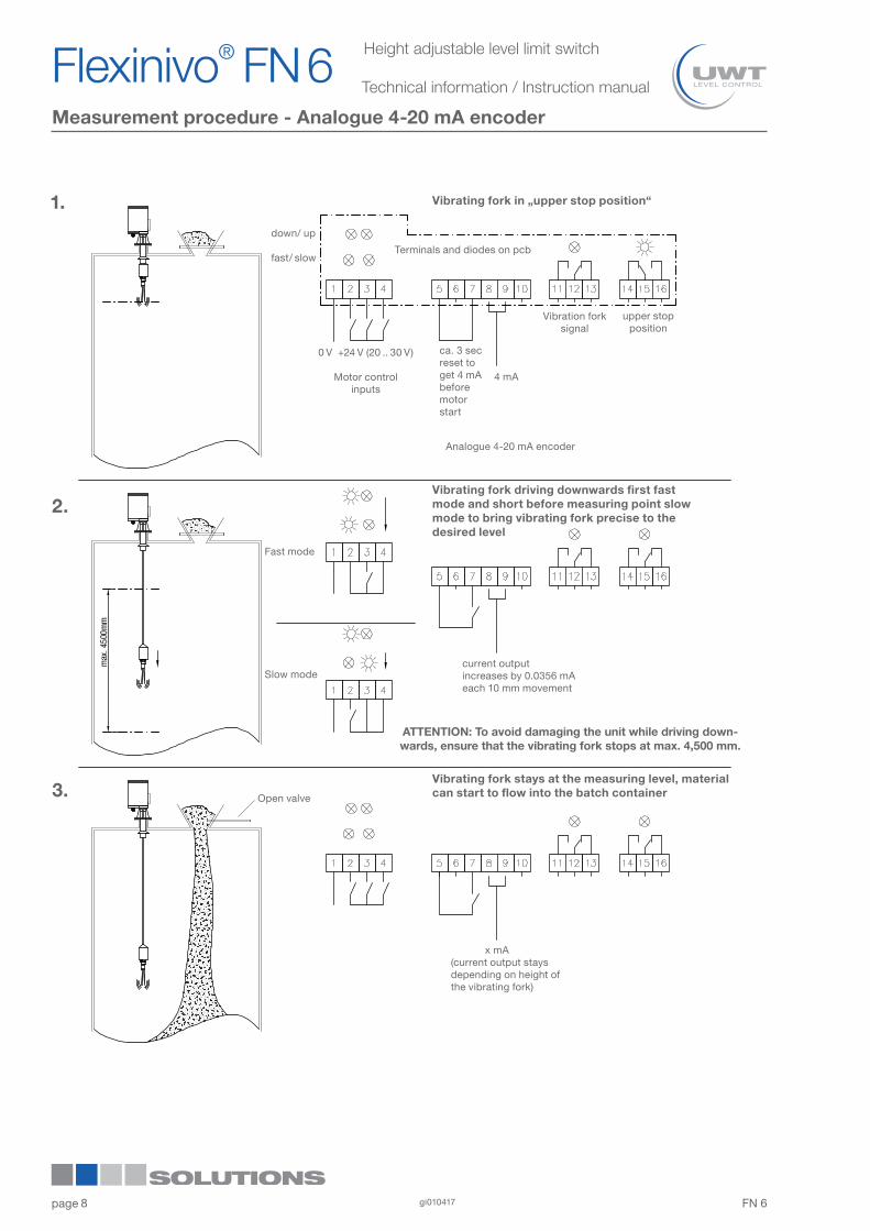
Measurement procedure - Analogue 4-20 mA encoder
down/ up
fast/ slow
Vibrating fork in „upper stop position“
Terminals and diodes on pcb
Vibration forksignal
upper stopposition
0 V +24 V (20 .. 30 V)
Motor control inputs
4 mA
Vibrating fork driving downwards first fast mode and short before measuring point slow mode to bring vibrating fork precise to the desired level
Fast mode
Slow mode
ATTENTION: To avoid damaging the unit while driving down-wards, ensure that the vibrating fork stops at max. 4,500 mm.
Vibrating fork stays at the measuring level, material can start to flow into the batch containerOpen valve
ca. 3 sec reset to get 4 mA before motor start
Analogue 4-20 mA encoder
current outputincreases by 0.0356 mA each 10 mm movement
x mA (current output stays depending on height of the vibrating fork)
Flexinivo® FN 61
2
3
4
5
6
7
8
9
10
11
12FN 6gi0104178
1.
2.
3.

Height adjustable level limit switch
Technical information / Instruction manual
page
Measurement procedure - Analogue 4-20 mA encoder
Vibrating fork detecting material
Vibrating fork goes back up after completing the measurement
Fast mode
Vibrating fork has reached the „upper stop position“
x mA (current output stays depending on height of the vibrating fork)
current outputdecreases by 0.0356 mA each 10 mm movement
ca. 4 mA
Flexinivo® FN 6 1
2
3
4
5
6
7
8
9
10
11
12FN 6 gi010417 9
4.
5.
6.

Height adjustable level limit switch
Technical information / Instruction manual
page
Manual motor operation
Vibrating fork driving downwards while pushing the buttons
Vibrating fork driving upwardswhile pushing the button
push button
fast mode down fast mode up
slow mode down
push button
Flexinivo® FN 61
2
3
4
5
6
7
8
9
10
11
12FN 6gi01041710

Height adjustable level limit switch
Technical information / Instruction manual
page
Safety instructions / Mounting
Safety instructions
- Installation, maintenance and commissioning may be
accomplished only by qualified technical personnel.
- The respectively valid installation instructions must be
observed.
- For terminal connection of the device, the local regulations or VDE0100 (Regulations of German electrotechnical Engineers)
must be observed.
- Use a fuse for the supply voltage (max. 6 A).
- Provide protection for relay contacts and output transistors to protect the device against spikes with inductive loads.
- Compare the supply voltage applied with the specifications
given on the name plate before switching the device on.
- Make sure that max. 8 mm of the pigtails are bared (danger of contact with live parts).
- Make sure that the boots for protecting cable terminations
are not longer than 8 mm (danger of contact with live parts).
- Make sure that the screwed cable gland safely seals the
cable and that it is tight (danger of water intrusion).
- A voltage-disconnecting switch must be provided near the
device.
- In the case of a defect, the distribution voltage must
automatically be cut off by a RCCB protection switch so as to
protect the user of the device from indirect contact with
dangerous electric tensions.
- In the case of inexpert handling or handling malpractice, the electric safety of the device cannot be guaranteed.
- Switch off the supply voltage before opening the device.
- Before opening the lid take care, that no dust deposits or
whirlings are present.
Mounting
The unit is mounted vertically with the flange on the silo. Avoid the point level switch to graze the socket (this causes wear of the cable).
The mounting position must be choosen carefully:
- cornices that might fall down may damage the point
level switch or the rope. Observe proper distance from silo wall.
- filling of the silo might cover the point level switch with material (prevent measuring during filling or observe proper distance to infeed).
- upward and downward movement of the point level switch must not be obstructed, even if the point level switch oscillates; observe proper distance to stanchions and built-in fittings.
The electrical connections are made in accordance with the connection diagram. Make sure, that the cable in the screwed cable gland is seated tightly without fail.
Close both lids of the housing, to prevent entrance of water into the housing.
When the unit is used in the open, we recommend to use the temperature protection cover. It protects the unit against moisture, heat and cold. If the ambient temperature can drop to less than 0°C the use of a temperature-protection-cover is obligatory.
Take care that the sensor never drives through the socket into the „upper stop position“ to avoid damage to the unit (see relevant dimensions page 2).
Socket
Point level switch
Cornices
Distance
Flexinivo® FN 6 1
2
3
4
5
6
7
8
9
10
11
12FN 6 gi010417 11

Height adjustable level limit switch
Technical information / Instruction manual
page
Commissioning
Warning:In case of inexpert handling or handling malpractice the safety of the device cannot be guaranteed.
1. Connect the unit with supply voltage and evaluation units
2. Cable conduit fittings, which are not used, must be
locked with a closing element.
3. Compare supply voltage and frequency with the type plate.
4. Switch on supply voltage and PLC.
5. Setting the max. drive length
The movable magnet avoids, that the probe may drive too far
and causes the unit to be damaged. When the magnet
reaches the sensor, the motor stops driving downwards.
Remove the magnet and drive the probe to the max. required
lenght by using the manual motor operation (see page 11) .
Then fix the magnet close to the sensor. It must be ensured,
that the probe moves max. 4,500mm downwards.
6. Test the function of the unit, the PLC and the
measurement functions.
7. The unit is now ready for work. Measurements can be
started.
Commissioning
Sensor for detecting the magnet
Movable magnet, used to limit the max. drive length
Flexinivo® FN 61
2
3
4
5
6
7
8
9
10
11
12FN 6gi01041712