flight manual ls1-f 0 amendments, list of effective … · copyright dg flugzeugbau gmbh - any copy...
TRANSCRIPT

Flight Manual LS1-f
Issued May 2011 0.1 Copyright DG Flugzeugbau GmbH - any copy or publishing prohibited
0 Amendments, list of effective pages, table of contents
0.1 Amendments Any revision of the present manual, except actual weighing data, must be recorded in the following table and in case of approved sections endorsed by the responsible airworthiness authority. The new or amended text in the revised page will be indicated by a black vertical line in the right hand margin, and the Revision No. and the date will be shown on the bottom left hand of the page.
No. Page
Description Date Inserted
Signature 1
0.0-7.6 Combination of the initial flight manuals of the Variants LS1-f and LS1-f (45), new standardized format
May 2011
2 1.1 -1.4, 2.1, 2.2, 2.6 � 2.9, 3.1 � 3.3, 4.1 � 4.14, 5.1, 5.2, 6.1 � 6.5, 7.1 � 7.5, 8.1 � 8.4, 9.1
Miscellaneous changes to the contents of the latest amendments of the initial flight manuals
May 2011

Flight Manual LS1-f
Issued May 2011 0.2 Copyright DG Flugzeugbau GmbH - any copy or publishing prohibited
Page intentionally left blank

Flight Manual LS1-f
Issued May 2011 0.3 Copyright DG Flugzeugbau GmbH - any copy or publishing prohibited
0.2 List of effective pages
Section page issued replaced replaced replaced 0 0.1 May 11 0.2 ″ 0.3 ″ 0.4 ″ 0.5 ″ 0.6 ″ 0.7 ″ 1 1.1 May 11 1.2 ″ 1.3 ″ 1.4 ″ 2 2.1 May 11 2.2 ″ 2.3 ″ 2.4 ″ 2.5 ″ 2.6 ″ 2.7 ″ 2.8 ″ 2.9 ″ 2.10 ″ 3 3.1 May 11 3.2 ″ 3.3 ″ 4 4.1 May 11 4.2 ″ 4.3 ″ 4.4 ″ 4.5 ″ 4.6 ″ 4.7 ″ 4.8 ″ 4.9 ″ 4.10 ″ 4.11 ″

Flight Manual LS1-f
Issued May 2011 0.4 Copyright DG Flugzeugbau GmbH - any copy or publishing prohibited
List of effective pages cont.
Section page issued replaced replaced replaced
4 4.12 May 11 4.13 ″ 4.14 ″ 5 5.1 May 11 5.2 ″ 5.3 ″ 6 6.1 May 11 6.2 ″ 6.3 ″ 6.4 ″ 6.5 ″ 7 7.1 May 11 7.2 ″ 7.3 ″ 7.4 ″ 7.5 ″ 8 8.1 May 11 8.2 ″ 8.3 ″ 8.4 ″ 9 9.1 May 11

Flight Manual LS1-f
Issued May 2011 0.5 Copyright DG Flugzeugbau GmbH - any copy or publishing prohibited
0.3 Table of contents Section Content page 0 Amendments, list of effective pages, table of contents ........................... 0.1 0.1 Amendments ............................................................................................ 0.1 0.2 List of effective pages.............................................................................. 0.3 0.3 Table of contents...................................................................................... 0.5
1 General ..................................................................................................... 1.1 1.1 Introduction.............................................................................................. 1.1 1.2 Certification basis .................................................................................... 1.1 1.3 Warnings, cautions and notes .................................................................. 1.2 1.4 Descriptive data ....................................................................................... 1.3 1.5 Three view drawing ................................................................................. 1.4
2 Limitations ............................................................................................... 2.1 2.1 Introduction.............................................................................................. 2.1 2.2 Airspeed ................................................................................................... 2.2 2.3 Airspeed Indicator Markings ................................................................... 2.3 2.3.1 LS1-f .................................................................................................. 2.3 2.3.2 LS1-f (45)........................................................................................... 2.3 2.4 Mass (weight)........................................................................................... 2.4 2.5 Centre of gravity ...................................................................................... 2.4 2.6 Approved manoeuvres ............................................................................. 2.4 2.7 Flight crew ............................................................................................... 2.5 2.8 Kinds of operation.................................................................................... 2.5 2.9 Minimum equipment................................................................................ 2.5 2.9.1 Normal operation ............................................................................... 2.5 2.9.2 In addition for cloud flying ................................................................ 2.5 2.10 Aerotow, winch and autotow launching .................................................. 2.6 2.10.1 Weak links.......................................................................................... 2.6 2.10.2 Towing cable for aerotow .................................................................. 2.6 2.10.3 Max. towing speeds ........................................................................... 2.6 2.10.4 Min. towing speeds for aerotow......................................................... 2.6 2.10.5 Tow Release....................................................................................... 2.6 2.11 Tyre Pressure ........................................................................................... 2.6 2.12 Waterballast ............................................................................................. 2.7 2.13 Limitations placards................................................................................. 2.8 2.13.1 Limitations placards LS1-f ................................................................ 2.8 2.13.2 Limitations placards LS1-f (45)......................................................... 2.9 2.13.3 LS1-f and LS1-f (45) ....................................................................... 2.10
3 Emergency procedures............................................................................. 3.1 3.1 Introduction.............................................................................................. 3.1 3.2 Canopy jettison ........................................................................................ 3.1 3.3 Bailing out................................................................................................ 3.1

Flight Manual LS1-f
Issued May 2011 0.6 Copyright DG Flugzeugbau GmbH - any copy or publishing prohibited
Section Content page 3.4 Stall characteristics and stall recovery..................................................... 3.1 3.5 Spinnng characteristics and Spin Recovery............................................. 3.2 3.6 Recovery from unintentional cloud flying............................................... 3.2 3.7 Emergency wheel up landing................................................................... 3.2 3.8 Emergency ground loop........................................................................... 3.2 3.9 Emergency landing on water ................................................................... 3.3
4 Normal procedures................................................................................... 4.1 4.1 Introduction.............................................................................................. 4.1 4.2 Rigging and derigging, filling and dumping the watertanks ................... 4.1 4.2.1 Rigging............................................................................................... 4.1 4.2.2 Handling and securing the L�Hotellier control quick connectors...... 4.2 4.2.3 Filling the water ballast tanks ............................................................ 4.3 4.2.4 Dumping the waterballast .................................................................. 4.3 4.2.5 Derigging ........................................................................................... 4.4 4.3 Daily Inspection ....................................................................................... 4.5 4.3.1 Inspection prior to rigging: ................................................................ 4.5 4.3.2 Inspection after rigging - Walk around the aircraft ........................... 4.6 4.3.3 Daily inspection after flight operaton ................................................ 4.8 4.3.4 Pre-flight inspection........................................................................... 4.8 4.4 Normal procedures and recommended speeds ........................................ 4.9 4.4.1 Aerotow.............................................................................................. 4.9 4.4.2 Winch launch ..................................................................................... 4.9 4.4.3 Free flight ......................................................................................... 4.10 4.4.4 Approach and landing ...................................................................... 4.11 4.4.5 Flight with water ballast................................................................... 4.12 4.4.6 Flight at high altitude and at low temperatures ............................... 4.13 4.4.7 Flights in rain and thunderstorms .................................................... 4.14 4.4.8 Cloud flying ..................................................................................... 4.14 4.4.9 Aerobatics ........................................................................................ 4.14
5 Performance ............................................................................................. 5.1 5.1 Airspeed indicator system calibration...................................................... 5.1 5.2 Stall speeds............................................................................................... 5.2 5.3 Demonstrated crosswing performance .................................................... 5.2 5.4 Gliding performance ................................................................................ 5.2 5.5 Flight polar............................................................................................... 5.3
6 Mass (weight) and balance ...................................................................... 6.1 6.1 Introduction.............................................................................................. 6.1 6.2 Weighing procedures ............................................................................... 6.1 6.3 Weighing record....................................................................................... 6.1 6.4 Basic empty mass and C.G. ..................................................................... 6.1 6.5 Mass of all non-lifting parts (WNLP)...................................................... 6.1 6.6 Max. mass (weight).................................................................................. 6.1

Flight Manual LS1-f
Issued May 2011 0.7 Copyright DG Flugzeugbau GmbH - any copy or publishing prohibited
Section Content page 6.7 Useful loads (payload) ............................................................................. 6.2 6.8 Loading chart ........................................................................................... 6.2 6.8.1 Cockpit load ....................................................................................... 6.2 6.8.2 Baggage.............................................................................................. 6.2 6.8.3 Waterballast in the wing tanks........................................................... 6.2 6.8.4 Weighing report (for section 6.3)....................................................... 6.3 6.8.5 Ballast chart (total ballast) ................................................................. 6.4
7 Sailplane and systems description ........................................................... 7.1 7.1 Introduction.............................................................................................. 7.1 7.2 Airframe ................................................................................................... 7.1 7.3 Placards .................................................................................................... 7.1 7.4 Aileron control ......................................................................................... 7.2 7.5 Elevator control, trim............................................................................... 7.2 7.6 Rudder Control......................................................................................... 7.2 7.7 Wheel brake ............................................................................................. 7.3 7.8 Airbrakes.................................................................................................. 7.3 7.9 Waterballast System................................................................................. 7.3 7.10 Cockpit ..................................................................................................... 7.3 7.11 Canopy ..................................................................................................... 7.3 7.12 Tow hooks................................................................................................ 7.3 7.13 Rudder pedal adjustment.......................................................................... 7.4 7.14 Seat, back rest and safety harness............................................................ 7.4 7.15 Instrument panel....................................................................................... 7.4 7.16 Baggage compartment ............................................................................. 7.4 7.17 Oxygen system......................................................................................... 7.4 7.18 Landing gear ............................................................................................ 7.4 7.19 Pitot-/Static pressure system.................................................................... 7.5 7.20 Canopy emergency release ...................................................................... 7.5
8 Sailplane handling, care and maintenance............................................... 8.1 8.1 Introduction.............................................................................................. 8.1 8.2 Inspection period, maintenance ............................................................... 8.1 8.3 Alterations or repairs................................................................................ 8.1 8.4 Tie Down, Parking ................................................................................... 8.2 8.5 Transport .................................................................................................. 8.2 8.6 Towing on the ground.............................................................................. 8.3 8.7 Cleaning and Care.................................................................................... 8.3 8.7.1 Hints for care...................................................................................... 8.3 8.7.2 Plexiglas canopy ................................................................................ 8.4 8.7.3 Metal parts.......................................................................................... 8.4
9 Supplements ............................................................................................. 9.1

Flight Manual LS1-f
Issued May 2011 1.1 Copyright DG Flugzeugbau GmbH - any copy or publishing prohibited
1 General
1.1 Introduction The sailplane flight manual has been prepared to provide pilots and instructors with information for the safe and efficient operation of the LS1-f and LS1-f (45). This manual includes the material required to be furnished to the pilot by the airworthiness requirements. It also contains supplemental data supplied by the glider manufacturer.
1.2 Certification basis This type of sailplane has been approved by the Luftfahrt-Bundesamt (LBA) in accordance with: Airworthiness requirements: “Airworthiness requirements forSailplanes “ LFS, issued 1966 and Standards for Structural Substantiation of Glass Fibre Reinforced Plastic Components for Sailplanes, issued March 1965 Type certified by EASA Type Certificate EASA A.095 Type LS-sailplanes. Date of certification: 30.08.2010 Initial type certification by LBA (Luftfahrt Bundesamt) with Type Certificate No. 262. Date of certification: Variant LS1-f: 30.08.1974 Variant LS1-f (45): 21.05.1976 Category of Airworthiness: "Utility"

Flight Manual LS1-f
Issued May 2011 1.2 Copyright DG Flugzeugbau GmbH - any copy or publishing prohibited
1.3 Warnings, cautions and notes
This manual was produced according to the flight manual specimen from the actual valid certification specifications CS22. It contains much more information than the initial manual. The following definitions apply to warnings, cautions and notes used in the flight manual:
"Warning" means that the non observation of the
corresponding procedure leads to an immediate or important degradation of the flight safety.
"Caution" means that the non observation of the corresponding procedure leads to a minor or to a more or less long term degradation of the flight safety.
"Note" draws the attention on any special item not directly related to safety but which is important or unusual.

Flight Manual LS1-f
Issued May 2011 1.3 Copyright DG Flugzeugbau GmbH - any copy or publishing prohibited
1.4 Descriptive data The LS1-f and LS1-f (45) are single-seater high performance sailplanes with conventional T-type horizontal tailplane. Technical details • Comfortable seating, backrest adjustable at ground. • Large canopy for good in-flight vision. • Sealed airbrake- and landing gear boxes. • Retractable main wheel, spring mounted. Wheel with drum brake actuated
via the airbrake handle. • Waterballast in the wings in waterbags
Technical data units LS1-f LS1-f (45)Wing span m 15 Wing surface m2 9,75 Aspect ratio / 23,1 Length m 6,75 Fuselage hight m 0,83 Fuselage width m 0,62 Horizontal tail span m 2,2 Horizontal tail surface m² 0,98 Waterballast kg (ltr.) max. 2* 45 max. 2*90Empty mass with min. equipment kg approx. 230 aprox. 235Wing loading (with 80kg payload) kg/m² approx. 32 approx. 32max. mass kg 390 439 max. wing loading kg/m² 40 45 Max. speed VNE km/h 250 270 Aerobatics / Not approved

Flight Manual LS1-f
Issued May 2011 1.4 Copyright DG Flugzeugbau GmbH - any copy or publishing prohibited
1.5 Three view drawing

Flight Manual LS1-f
Issued May 2011 2.1 Copyright DG Flugzeugbau GmbH - any copy or publishing prohibited
2 Limitations
2.1 Introduction Section 2 includes operating limitations, instrument markings and basic placards necessary for safe operation of the gliders LS1-f and LS1-f (45), its standard systems and standard equipment. The limitations included in this section have been approved.
Flight Manual LS1-f
Issued May 2011 2.2 Copyright DG Flugzeugbau GmbH - any copy or publishing prohibited
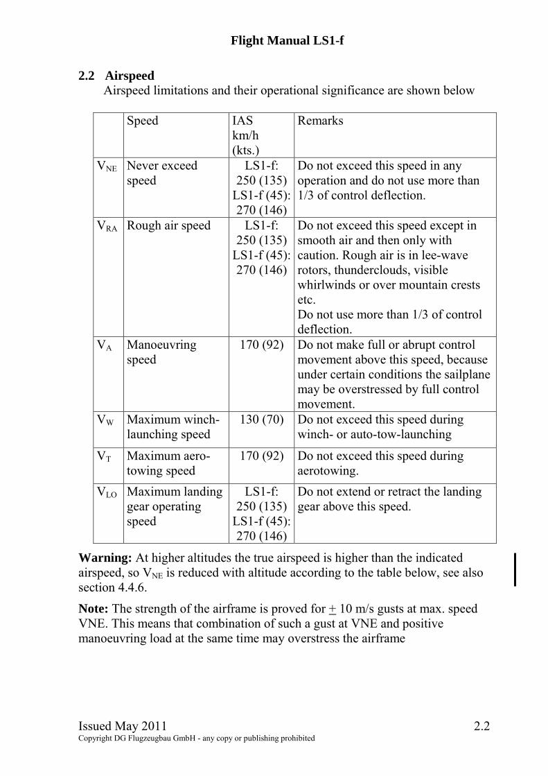
2.2 Airspeed
Airspeed limitations and their operational significance are shown below
Speed IAS km/h (kts.)
Remarks
VNE Never exceed speed
LS1-f: 250 (135)
LS1-f (45):270 (146)
Do not exceed this speed in any operation and do not use more than 1/3 of control deflection.
VRA Rough air speed LS1-f: 250 (135)
LS1-f (45):270 (146)
Do not exceed this speed except in smooth air and then only with caution. Rough air is in lee-wave rotors, thunderclouds, visible whirlwinds or over mountain crests etc. Do not use more than 1/3 of control deflection.
VA Manoeuvring speed
170 (92) Do not make full or abrupt control movement above this speed, because under certain conditions the sailplane may be overstressed by full control movement.
VW Maximum winch-launching speed
130 (70) Do not exceed this speed during winch- or auto-tow-launching
VT Maximum aero-towing speed
170 (92) Do not exceed this speed during aerotowing.
VLO Maximum landing gear operating speed
LS1-f: 250 (135)
LS1-f (45):270 (146)
Do not extend or retract the landing gear above this speed.
Warning: At higher altitudes the true airspeed is higher than the indicated airspeed, so VNE is reduced with altitude according to the table below, see also section 4.4.6.
Note: The strength of the airframe is proved for + 10 m/s gusts at max. speed VNE. This means that combination of such a gust at VNE and positive manoeuvring load at the same time may overstress the airframe

Flight Manual LS1-f
Issued May 2011 2.3 Copyright DG Flugzeugbau GmbH - any copy or publishing prohibited
2.3 Airspeed Indicator Markings
Airspeed indicator markings and their colour code significance are shown below.
2.3.1 LS1-f Marking (IAS) value or
range km/h (kts.) Significance
Green Arc
80 � 170 (43 - 92)
Normal Operating Range (Lower limit is maximum weight 1.1*VS1 at most forward c.g. with flaps neutral. Upper limit is rough air speed.)
Yellow Arc
170 -250 (92 � 135)
Manoeuvres must be con ducted with caution and only in smooth air
Red Line 250 (135) Maximum speed for all operations 2.3.2 LS1-f (45)
Marking (IAS) value or range km/h (kts.)
Significance
Green Arc
80 � 170 (43 - 92)
Normal Operating Range (Lower limit is 1.1*VS1 at maximum weight and most forward c.g.. Upper limit is rough air speed.)
Yellow Arc
170 -270 (92 � 146)
Manoeuvres must be con ducted with caution and only in smooth air
Red Line 270 (146) Maximum speed for all operations

Flight Manual LS1-f
Issued May 2011 2.4 Copyright DG Flugzeugbau GmbH - any copy or publishing prohibited
2.4 Mass (weight)
Maximum take off and landing weight with waterballast LS1-f: 390 kg (860 lbs.) LS1-f (45): 439 kg (968 lbs.)
Caution: It is recommended to dump the waterballast before landing on airfields. Dump the ballast before an outlanding in any case.
Maximum take-off and landing mass without waterballast: W= WNLP + Wwings WNLP = Maximum mass of the non lifting parts (see below) Wwings = actual mass of the wings
Maximum weight of the non lifting parts = 230 kg 507 lbs.
Maximum mass in baggage compartment: 12 kg 26.5 lbs.
Caution: Heavy pieces of baggage must be secured to the baggage compartment floor.
Maximum waterballast Variant mass kg (litres) mass US.gal. mass lbs. LS1-f 2 x 45 2 x 11.9 2 x 99 LS1-f (45) 2 x 90 2 x 23.8 2 x 198 The max. take off mass is not to be exceeded.
Warning: Follow the loading procedures see section 6. 2.5 Centre of gravity
Centre of gravity range in flight is: 220mm (8.66 in.) up to 420mm (16.53 in.) behind datum.
Datum= wing leading edge at the rootrib. Reference line= underside of aft fuselage boom horizontal.
C.G. diagrams and loading chart see sect. 6. 2.6 Approved manoeuvres
This sailplane is certified for normal gliding in the "Utility" category. Aerobatics are not approved.

Flight Manual LS1-f
Issued May 2011 2.5 Copyright DG Flugzeugbau GmbH - any copy or publishing prohibited
2.7 Flight crew
Max. load in the seat: 110 kg (242 lbs.) unless limited by the max. permissible mass of the nonlifting parts (230 kg, 507 lbs). Min. load in the seat (pilot + parachute):60 kg (132 lbs.). If necessary the min. cockpit load may be increased according to maintenance manual section 2.2.1 and value entered in section 6.8.4. With these loads, the C.G. range given under section 2.5 will be kept within the limits when the empty weight C.G. is within its limits. See loading chart in section 6.
Caution: With lower pilot weights lead ballast must be added to the seat. Ballast put on the seat (lead ballast cushion) must be fastened at the safety belt anchor points. 2.8 Kinds of operation
Flights according to VFR (daylight) Aerotow Winch- and auto-tow launching Aerobatics are not permitted Cloud flying (daylight): permitted when properly instrumented (see below).
2.9 Minimum equipment As minimum equipment only the instruments and equipment specified in the equipment list (see Maintenance Manual section 6) are admissible.
2.9.1 Normal operation a) Airspeed indicator: Range: 0-300 km/h (0-135kts.);
Speed range markings see sect. 2.3 b) Altimeter: Range: 0 � min. 10.000 m (0 � min. 30000 ft),
Altimeter with fine range pointer, 1 turn max. 1000 m (3000 ft.) c) Four piece symmetrical safety harness d) Parachute automatic or manual type or a suitable firm back
cushion compressed approx. 8 cm (3 in.) thick e) Required placards, check lists, Flight manual.
2.9.2 In addition for cloud flying (Not permitted in the USA, Canada and Australia) Magnetic compass (compensated in the airdraft) VHF - transceiver (ready for operation) Variometer Turn and bank indicator or artificial horizon
Note: Experience has shown that the installed airspeed indicator system may be used for cloud flying. Caution: The weight of the upper part of the instrument panel shall not exceed 4 kg (8.8 lbs.).

Flight Manual LS1-f
Issued May 2011 2.6 Copyright DG Flugzeugbau GmbH - any copy or publishing prohibited
2.10 Aerotow, winch and autotow launching 2.10.1 Weak links
Winch launch aero tow max. 5500 N (1240 lbs.) 5500 N (1240 lbs.) recommended 5000 N + 500 N
(1120 + 112 lbs.) 5000 N + 500 N (1120 + 112 lbs.) behind aircraft 3000 N + 300 N (670+ 67 lbs.) behind ultralight aircraft or powerded sailplanes
2.10.2 Towing cable for aerotow Length: 30-70 m (100 - 230 ft) Material: hemp- or plastic fibres
2.10.3 Max. towing speeds maximum maximum Aerotow VT = 170 km/h 92 kts. Winch- and autotow VW = 130 km/h 70 kts.
2.10.4 Min. towing speeds for aerotow LS1-f and LS1-f (45) No waterballast 100 km/h 54 kts. LS1-f With waterballast 110 km/h 59 kts. LS1-f (45) With waterballast 120 km/h 65 kts.
2.10.5 Tow Release The C.G. tow release (installed in front of the main wheel at the LG fork) is suitable for winch and auto-tow launching as well as for aerotow.
Warning: When towing at the C.G. hook don�t retract the landing gear. Caution: If an additional front hook is installed according to TN59 this hook is to be used for aerotow. In case to pitot pressure port is installed in the fuselage nose the ASI indication may be lower than real during aerotow depending on cable ring position. 2.11 Tyre Pressure
Main wheel 3,0 bar (43.5 psi)

Flight Manual LS1-f
Issued May 2011 2.7 Copyright DG Flugzeugbau GmbH - any copy or publishing prohibited
2.12 Waterballast
Filling the water ballast is only allowed with a filling system which enables determination of the exact amount of ballast filled, e.g. water gauge or calibrated canisters. Only symmetrical loading is allowed. After filling, balance the wings by dumping enough water from the heavy wing,.
Warning: Follow the loading chart, see section 6.8. Don�t try to fill more water into the tanks than the specified values. The max. take off weight must not be exceeded.

Flight Manual LS1-f
Issued May 2011 2.8 Copyright DG Flugzeugbau GmbH - any copy or publishing prohibited
2.13 Limitations placards 2.13.1 Limitations placards LS1-f
Cockpit Checklist This sailplane must be operated in compliance with
operating limitations as stated in the form of markings, placards and flight manual.
1. Trim ballast (for under weight pilot)? 2. Loading plan regarded? 3. Parachute worn properly, static line connected? 4. Seat back and rudder pedals in comfortable position ?5. Safety harness buckled ? 6. All controls and instruments in reach? 7. Air brakes cycled and locked? 8. Trim position ? 9. Altimeter adjusted? 10. Positive control check ? (One person at the control
surfaces). 11. Tail dolly removed ? 12. Tow release checked? 13. Canopy locked? Clearly visible at right cockpit wall
Type: LS1-f Serial No.: ____________ Registration: __________
Airspeed limits: Winch launch and auto tow 130 km/h 81 mph 70 kts. Aero tow 170 km/h 106 mph 92 kts. Manoeuvring 170 km/h 106 mph 92 kts. Rough air 250 km/h 155 mph 135 kts. Never exceed 250 km/h 155 mph 135 kts. Aerobatic manoeuvres are prohibited Max. take-off mass 390 kg 860 lbs. Pilot weight incl. max: 110 kg 242 lbs. Parachute min: 60 kg 132 lbs. With lower pilot weight necessary ballast must be added. Clearly visible at right cockpit wall Altitude in [m] 0-2000 3000 4000 5000 6000 7000 8000 9000 10000
VNE IAS km/h 250 237 225 214 202 191 180 170 160
Altitude in [ft] 0-6560 9843 13124 16405 19685 22966 26247 29528 32809
VNE IAS kts. 135 128 122 115 109 103 97 92 86

Flight Manual LS1-f
Issued May 2011 2.9 Copyright DG Flugzeugbau GmbH - any copy or publishing prohibited
2.13.2 Limitations placards LS1-f (45)
Cockpit Checklist This sailplane must be operated in compliance with
operating limitations as stated in the form of markings, placards and flight manual.
1. Trim ballast (for under weight pilot)? 2. Loading plan regarded? 3. Parachute worn properly, static line connected? 4. Seat back and rudder pedals in comfortable position ?5. Safety harness buckled ? 6. All controls and instruments in reach? 7. Airbrakes cycled and locked? 8. Trim position ? 9. Altimeter adjusted? 10. Positive control check ? (One person at the control
surfaces). 11. Tail dolly removed ? 12. Tow release checked? 13. Canopy locked? Clearly visible at right cockpit wall
Type: LS1-f (45) Serial No.: ____________ Registration: __________
Airspeed limits: Winch launch and auto tow 130 km/h 81 mph 70 kts. Aero tow 170 km/h 106 mph 92 kts. Manoeuvring 170 km/h 106 mph 92 kts. Rough air 270 km/h 167 mph 146 kts. Never exceed 270 km/h 167 mph 146 kts. Aerobatic manoeuvres are prohibited Max. take-off mass 439 kg 968 lbs. Pilot weight incl. max: 110 kg 242 lbs. Parachute min: 60 kg 132 lbs. With lower pilot weight necessary ballast must be added. Clearly visible at right cockpit wall Altitude in [m] 0-2000 3000 4000 5000 6000 7000 8000 9000 10000
VNE IAS km/h 270 256 243 231 218 206 195 184 173
Altitude in [ft] 0-6560 9843 13124 16405 19685 22966 26247 29528 32809
VNE IAS kts. 146 138 131 125 118 111 105 99 93
Clearly visible at right cockpit wall

Flight Manual LS1-f
Issued May 2011 2.10 Copyright DG Flugzeugbau GmbH - any copy or publishing prohibited
2.13.3 LS1-f and LS1-f (45)
Min. Cockpit Load: kg If not 60 kg, clearly visible at instrument panel
Tyre pressure 3,0 – 3,5 bar 43,5 – 51 psi
On right landing gear door
Baggage load Max. 12 kg (26.5 lbs.) At baggage compartment
Weak link max. 550 daN (1213 lbs.) On left landing gear d
Flight Manual LS1-f
Issued May 2011 3.1 Copyright DG Flugzeugbau GmbH - any copy or publishing prohibited
3 Emergency procedures
3.1 Introduction Section 3 provides a checklist and amplification for coping with emergencies that may occur.
Caution: Canopy jettison and bailing out should be trained several times on the ground before flying the aircraft. 3.2 Canopy jettison
To bail out pull the red canopy emergency release handle until the canopy hinge disengages and moves downwards, then open canopy locking handles. Then push the canopy upwards with both hands. If TN 61-LS has been executed: To bail out open both canopy locking handles, then pull the red canopy emergency release handle until the canopy hinge disengages. A spring at the canopy hinge lifts the canopy in at the front end. Only in case the canopy doesn�t separate by itself from the fuselage, you have to push the canopy upwards with both hands on the Plexiglas. The latch on the rear of the canopy is held back by a spring in the fuselage. This creates a point of rotation to ensure a safe separation of the canopy.
3.3 Bailing out First jettison the canopy, then unlock the safety harness and bail out. The low cockpit walls allow for a quick push-off exit.
3.4 Stall characteristics and stall recovery When reaching the stall the aircraft begins to oscillate around it�s longitudinal axis and one wing may drop. The pilot may prevent the wing drop by using the ailerons. Pronounced rudder deflection in the direction of the lower wing will result in a full stall. If the C.G. is in a rearward position this may result in a spin. Easing the stick forward and picking up a dropping wing with sufficient opposite rudder the glider can be recovered from the stall. To recognize and prevent the stall, please refer to section 4.4.3.

Flight Manual LS1-f
Issued May 2011 3.2 Copyright DG Flugzeugbau GmbH - any copy or publishing prohibited
3.5 Spinnng characteristics and Spin Recovery
Spins are significantly influenced by the C.G. position. When the C.G. is in a forward position sustained spinning is not possible. When the C.G. is in a mid or rearward position sustained spinning is possible. Air flow during the spin may push the rudder to maximum deflection. In this case full rudder must be used opposite to the direction of spin. Stopping the spin: Apply full opposite rudder against direction of spin. Then ease stick forward until the rotation ceases, at aft C.G. positions at which the glider spins with the nose up, it is necessary to apply full stick forward. Centralise the controls and carefully pull out of the dive. The ailerons should be kept neutral during recovery.
Caution: To prevent unintentional spinning do not stall the sailplane. Fly with enough speed reserve especially in gusty conditions and in the landing pattern. Intentional spinning is prohibited. Recover immediately from an unintentional spin. 3.6 Recovery from unintentional cloud flying
Spins are not to be used to loose altitude. In an emergency, pull out the airbrakes fully before exceeding a speed of 170 km/h (92 kts.) and fly with max. 170 km/h (92 kts.) until leaving the cloud. At higher speeds up to VNE pull out the airbrakes very carefully because of high aerodynamic and g-loads. Retraction and extension of the airbrakes is possible up to VNE.
3.7 Emergency wheel up landing It is not recommended to execute a wheel up emergency landing, as the energy absorption capability of the fuselage is much smaller than that of the landing gear. If the landing gear can't be extended touch down with small angle of attack.
3.8 Emergency ground loop If there is the risk of overshooting the landing strip you have to decide at least 40 m (130 ft) before the end of the field to execute a controlled ground loop: - If possible turn into the wind! - At the same time try to decrease tail load by pushing the stick forward.

Flight Manual LS1-f
Issued May 2011 3.3 Copyright DG Flugzeugbau GmbH - any copy or publishing prohibited
3.9 Emergency landing on water
From the experience with emergency water landing we know that it is likely that the glider will dive into the water, cockpit first. Therefore an emergency landing on water should be the last choice.
Caution: In the case of a water landing extend the landing gear. Recommended procedures : On downwind leg of the landing pattern: Extend the landing gear, unlock
the parachute harness (not the seat harness) Touch down: With landing gear extended and airspeed as low as possible. At point of touch-down: Use your left arm to protect your face against
possible canopy fracture. After touch down: Unfasten seat belt harness and undo parachute. Leaving the cockpit under water: If the canopy has not fractured, opening
the canopy may be possible only after the forward fuselage is almost completely filled with water.
Note: Always try to land parallel to the shore. If there is a flow always land with the flow.

Flight Manual LS1-f
Issued May 2011 4.1 Copyright DG Flugzeugbau GmbH - any copy or publishing prohibited
4 Normal procedures
4.1 Introduction This section provides checklist and amplification procedures for the conduct of normal operation. Normal procedures associated with optional systems can be found in section 9.
4.2 Rigging and derigging, filling and dumping the watertanks 4.2.1 Rigging Caution: When rigging the glider from the trailer be sure to have enough clearance when extending the landing gear to avoid the wheel touching the ground. Lifting the fuselage with the landing gear will result in damage of the landing gear control system. 1. Execute the inspection prior to rigging see section 4.3. 2. Clean and lube the pins and bushings. 3. Open the canopy, extend the landing gear. 4. With a helper on the wingtip, push left wing into place, care for correct
dihedral. 5. With a helper on the wingtip, push right wing into place, care for correct
dihedral. 6. Sight through the wing main pin bushings to determine alignment. Push the
main pins in as far as possible. 7. Secure the main pins by pulling the securing hooks to the front, rotate the
handles of the pins upwards and secure the handles with the hooks. 8. Connect the airbrake quick connectors and secure the connectors according
to section 4.2.2. Check manually by pulling upwards. 9. Connect the aileron quick connectors and secure the connectors according
to section 4.2.2. Check manually by pulling upwards. 10. Install the horizontal tail and secure with the safety nut against the tapered
bolts. 11. Install TE-probe and secure with tape against rotation. 12. Install and secure equipment like a Logger in the baggage compartment. 13. In case of an automatic parachute fix rip cord to the ring mounted to the left
hand shoulder harness attachment. 14. Tape the gaps of the wing-fuselage junction and at the tailplane. 15. Execute a positive control check, one helper is needed to hold firmly the
control surfaces.
Flight Manual LS1-f
Issued May 2011 4.2 Copyright DG Flugzeugbau GmbH - any copy or publishing prohibited
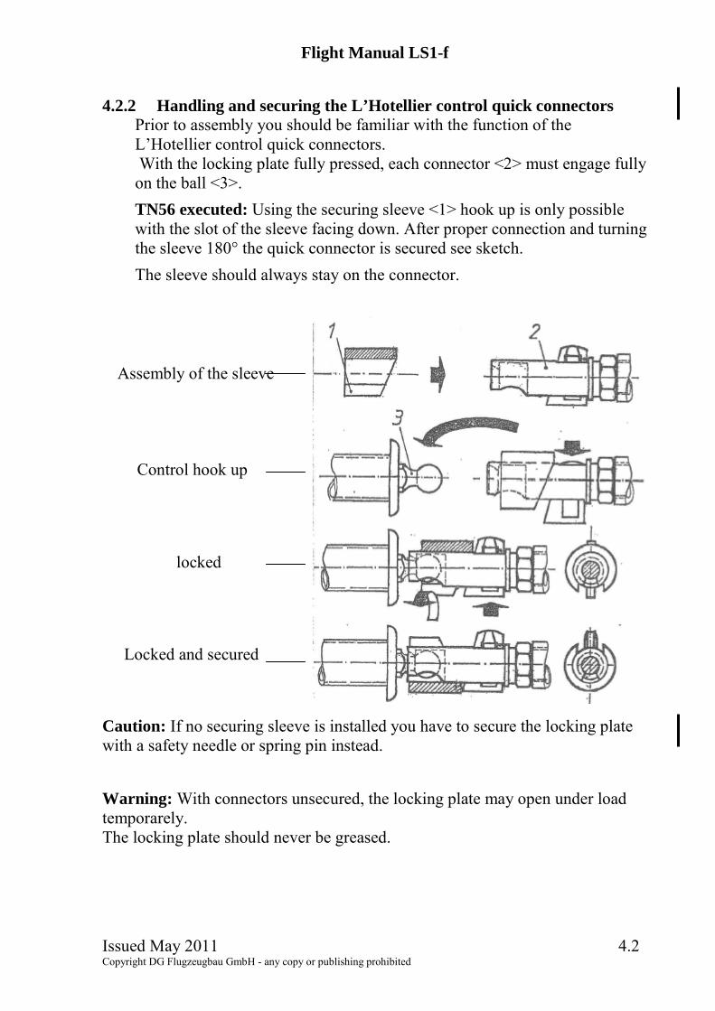
4.2.2 Handling and securing the L’Hotellier control quick connectors
Prior to assembly you should be familiar with the function of the L�Hotellier control quick connectors. With the locking plate fully pressed, each connector <2> must engage fully on the ball <3>. TN56 executed: Using the securing sleeve <1> hook up is only possible with the slot of the sleeve facing down. After proper connection and turning the sleeve 180° the quick connector is secured see sketch. The sleeve should always stay on the connector.
Caution: If no securing sleeve is installed you have to secure the locking plate with a safety needle or spring pin instead. Warning: With connectors unsecured, the locking plate may open under load temporarely. The locking plate should never be greased.
Assembly of the sleeve
Control hook up
locked
Locked and secured

Flight Manual LS1-f
Issued May 2011 4.3 Copyright DG Flugzeugbau GmbH - any copy or publishing prohibited
4.2.3 Filling the water ballast tanks
1. Close dump valve. 2. Rest the wing tip of the wing to be filled on the ground. 3. Connect loading funnel and load water carefully, respect section 2.12.
Do not fill tank completely, as too much water would drain into fuselage when connecting the waterhose to the dump valve.
4. Connect the waterhose to the dump valve (dump valve still closed). 5. Now proceed with the other wing, see items 2 � 4. 6. Test hoses for leaks and check drain holes. 7. After loading ballast, level wings and check for imbalance. Correct
imbalance by draining the required amount from the heavy wing. 8. Grease the threads of the PVC parts every now and then, otherwise they
may be hard to open again, because they tend to lock with water. Warning: Never fill the wing tanks from a main pressure water supply. Filling the wing tanks with excessive pressure (more than 0.2 bar, 3 psi) will definitely burst the wing shell! The same applies for the fin tanks. 4.2.4 Dumping the waterballast
Dumping is via one central valve located on top of the landing gear box through the landing gear box. On the ground you may dump water from one tank if you rest the opposite wing on the ground. 1. Extend the landing gear. 2. Open dump valve, complete dumping takes about 2 minutes (LS1-f) or 4
minutes (LS1.f(45)). 3. Leave dump valve open to avoid pressure difference in waterballast-
system when changing altitude. Caution: As the water drains through the landing gear box always extend the landing gear prior to dumping the water. Otherwise the landing gear box will be filled with water and the wheel brake might become wet and will not brake sufficiently.

Flight Manual LS1-f
Issued May 2011 4.4 Copyright DG Flugzeugbau GmbH - any copy or publishing prohibited
4.2.5 Derigging
Derigging follows the reverse of rigging, see section 4.2.1. Waterballast must be dumped first.
Caution: Lift wings far enough that you can turn the main pins. The resulting dihedral shall be maintained during the whole derigging procedure of the wings to avoid damage to the fuselage

Flight Manual LS1-f
Issued May 2011 4.5 Copyright DG Flugzeugbau GmbH - any copy or publishing prohibited
4.3 Daily Inspection
Please keep in mind the importance of the inspection after rigging the glider and respectively each day prior to the first take off. It is for your safety.
Caution: After a heavy landing or if other high loads have been imposed on your sailplane, you must execute a complete inspection referring to maintenance manual sect. 3.2 prior to the next take off. If you detect any damage, don't operate your aircraft before the damage is repaired. If the maintenance manual doesn't give adequate information, please contact the manufacturer. 4.3.1 Inspection prior to rigging:
1. Wing roots and spar ends a) Check for cracks, delamination etc.; b) Check the lift pins and their glued connection in root ribs and the
bushes in the spar ends for wear; c) Check the balls of the control quick connectors at the rootrib for wear
and corrosion; d) Check if the drain holes in the root ribs are not clogged; e) Check the hoses and screwed joints of the waterballast system
2. Fuselage at wing connection a) Check the lift bushes for wear and corrosion; b) Check the control quick connectors for wear and corrosion. c) Check the dump vlave of the waterballast system
3. Top of the vertical fin a) Check the mounting points of the horizontal tailplane and the elevator
control hook up for wear and corrosion b) Check that the ball of the rod end of the front tailplane mount is glued
fix. Warning: Don�t operate the glider with a loose ball.
4. Horizontal tailplane Check the mounting points and the elevator control hook up for wear and corrosion.

Flight Manual LS1-f
Issued May 2011 4.6 Copyright DG Flugzeugbau GmbH - any copy or publishing prohibited
4.3.2 Inspection after rigging - Walk around the aircraft
1. All parts of the airframe a) check for flaws such as bubbles, holes, bumps and cracks in the surface; b) Check leading and trailing edges of the wings and control surfaces for
cracks; 2. Cockpit area
a) Check the canopy locking mechanism; b) Check the canopy emergency release see section 7.20 (not each day, but
min. every 3 month); c) Ceck the main pin securing; d) Check all controls for wear and function, incl. positive control check; e) Check the tow release system for wear and function incl. cable release
check; f) Check for foreign objects; g) Check the instrumentation for wear and function; h) Check if the correct battery is installed, secured and connected i) Check all fuses incl. the fuse at the battery
3. Function check of the control quick connectors of ailerons and airbrakes: After the positive control check try to turn and move the connectors in all possible directions and pull with a force of 50 N (10lbs.) upwards. If you can�t pull off the connectors from the balls the controls are connected properly. Additional securing should be done with LS- securing sleeves �White� part No. 4R10-188 according to TN56 or with safety needles or spring pins.
4. C.G. Tow hook a) Check the ring muzzle of the C.G. hook for wear and function; b) Check both tow hooks (if installed) for cleanliness and corrosion;
5. Landing gear a) Check the struts, the gear box, the gear doors and the tyre for wear; dirt
in the struts can hinder the landing gear from locking over centre the next time!;
b) Check the tyre pressure; 3 - 3.5 bar (43.5 - 51 psi);
c) Check wheel brake and cable for wear; d) Check wheel brake function: e) Check if drain holes in front and behind landing gear box are open;

Flight Manual LS1-f
Issued May 2011 4.7 Copyright DG Flugzeugbau GmbH - any copy or publishing prohibited
Inspection after rigging cont. 6. Left wing
a) Check the aileron for excessive free play; b) Check the aileron drive if loose; c) Check airbrake, airbrake box and control rod for wear and free play. It
must be possible to retract the airbrake, even if it is pressed backwards in direction of flight. If there is any water in the airbrake box, this has to be removed;
d) Check the wing shells for dents, delaminations and cracks, especially close to the wing spars;
e) Check leading and trailing edges for damage; f) Check aileron seals, see section 4.5 MM.
7. Tail skid a) Check for good glued joint to fuselage, check if the skid is mounted in
the correct direction, the cable deflector and the corresponding cut out in the skid plate must be at the front end;
b) Check if drain hole in front of tail skid are open; 8. Rear end of the fuselage
a) Check the lower rudder hinge and the connection of the rudder cables for wear, free play and correct securing;
b) Check the bulkhead and fin trailing edge shear web for cracks and delamination;
9. Fin - horizontal tail a) Check the upper rudder hinge for wear and free play; b) Check the elevator for free play and correct control hook up; c) Check the securing of the of the tailplane (spring or ratched according
to TN51); d) Check the horizontal tail for free play; e) Check leading and trailing edges for damage; f) Check ports for total/Pitot pressure (if installed) and TE-probe for free
passage; g) Check the TE probe for correct insertion and fix it with tape; h) Check elevator seals, see MM section 4.5.
10. Right wing see item 6. 11. Fuselage nose
Check the ports for the static pressure and the pitot pressure for cleanliness.

Flight Manual LS1-f
Issued May 2011 4.8 Copyright DG Flugzeugbau GmbH - any copy or publishing prohibited
4.3.3 Daily inspection after flight operaton 1. Remove bugs and dirt. 2. Remove any water from the airbrake boxes. 3. Check if waterballast is dumped completely.
4.3.4 Pre-flight inspection 1. Trim ballast (for under weight pilot)? 2. Loading plan regarded? 3. Parachute worn properly, static line connected? 4. Seat back and rudder pedals in comfortable position ? 5. Safety harness buckled ? 6. All controls and instruments in reach? 7. Airbrakes cycled and locked? 8. Trim position ? 9. Altimeter adjusted? 10. Positive control check performed? (One person at the control
surfaces). 11. Tail dolly removed ? 12. Tow release checked? 13. Canopy locked?

Flight Manual LS1-f
Issued May 2011 4.9 Copyright DG Flugzeugbau GmbH - any copy or publishing prohibited
4.4 Normal procedures and recommended speeds 4.4.1 Aerotow
Due to the central towhook position being in the middle of the fuselage and the good effectiveness of the ailerons and rudder, the possibility of wing dropping or ground loops, even on a slowly accelerating aerotow is reduced. Take-off with strong crosswind is possible. If only a C.G. release is installed, then the aerotow is to be executed with this one. Set trim to full nose down for aerotow. Hold the stick in the forward position. Don't try to lift off before you reach an airspeed of 80 km/h (43 kts.) (without ballast). On a rough airfield hold the control stick tight. Normal towing speed is 110-130 km/h (59-70 kts.). For a cross country tow the speed can be as high as 170 km/h (92 kts.).
Caution: If an additional tow release for aerotow is installed according to TN59, only this release should be used for aerotow. Adjust the trim for aerotow to fully nose down position. In case the pitot pressure port is installed in the fuselage nose the ASI indication may be lower than real during aerotow depending on cable ring position. 4.4.2 Winch launch
Winch launch is only allowed at the C.G. tow hook! Set trim to nose down for a winch launch. Use the normal winch launch procedure. After reaching safety altitude gradually pull back on the stick so that the glider will not pick up excessive speed. After reaching release altitude pull the tow release knob. The recommended winch launch airspeed is 110-120 km/h (60-65 kts.).
Caution: Seat harness should be tightened firmly prior to take off. Backrest and headrest should be adjusted to avoid the pilot sliding backwards due to acceleration and during climb. During the acceleration phase and initial climb the control stick must be held in the forward position, to avoid excessive nose-up pitching rotation.
Warning: Due to the low position of the C.G. hook there is a tendency for pitching nose up during the initial launch. This tendency is more pronounced with high take-off mass (e.g. full waterballast) and rear C.G. position. An abrupt initial pulling of the winch increases the pitching-up tendency of the glider and should be avoided.
Caution: Do not fly at less than 100 km/h (54 kts.) or not more than 130 km/h (70 kts.). Don�t retract the landing gear during lauch as the tow release is mounted at the landing gear.

Flight Manual LS1-f
Issued May 2011 4.10 Copyright DG Flugzeugbau GmbH - any copy or publishing prohibited
4.4.3 Free flight
Stalling characteristics (straight and turning flight) When reaching the stall the aircraft begins to oscillate around it�s longitudinal axis and one wing may drop. The pilot may prevent the wing drop by using the ailerons. Aileron effectiveness is still available, but reaction speed is reduced. Pronounced rudder deflection in the direction of the lower wing will result in a full stall. If the C.G. is in a rearward position this may result in a spin. The glider can be recovered from the stall by easing the stick forward and with sufficient rudder opposite to direction of turn Loss of height is approx. 40m (130ft). For stall airspeeds see section 5.2.
Caution: With empty water tanks, leave dump valve open to avoid pressure pick-up in waterballast-system due to changes of altitude. system when changing altitude.
Caution: Flights in conditions conducive to lightning strikes must be avoided. High speed flying The LS1-f / LS1-f (45) can be trimmed almost up to high speeds. Nevertheless don't release the stick at any time. Watch airspeed indication because red line speed may easily be exceeded inadvertently due to the shallow descent angle and low wind noise.
Warning: Do not exceed the max. permissible airspeeds (see sect. 2.2).
Caution: If redline speed is exceeded for any reason, extend the airbrakes cautiously Retraction and extension of the airbrakes is possible up to VNE.

Flight Manual LS1-f
Issued May 2011 4.11 Copyright DG Flugzeugbau GmbH - any copy or publishing prohibited
4.4.4 Approach and landing
It is recommended to dump the waterballast before landing on airfields. Dump the ballast before an outlanding in any case. Abeam the landing point extend the landing gear. In calm weather approach with approx. 90 km/h (49 kts.) (ballast dumped!). With strong wind fly faster! The effective airbrakes allow wide control of the glide angle.
Caution: Stall speed increases about 10 km/h (5 kts.) when airbrakes are extended. Do not approach too slowly with fully extended airbrakes otherwise the aircraft may drop during flare out. When flaring out keep the airbrake setting you were using, opening them further may drop the sailplane.
Note: When the C.G. is in a forward position and airbrakes are extended side slipping should be avoided as elevator effectiveness is not sufficient to fly with low speed.
Caution: You should land also on soft fields with the landing gear extended, as there is no tendency of nosing over, if the stick is pulled backwards.
Note: Clean the landing gear and G.G. tow release after landing in a muddy field. Dirt in the struts can keep the landing gear from locking over centre next time.
Landing with the landing gear retracted Wheel-up landing is not recommended see emergency procedures, section 3.8. After a wheel-up landing check the fuselage belly and the C.G. tow hook for damage.

Flight Manual LS1-f
Issued May 2011 4.12 Copyright DG Flugzeugbau GmbH - any copy or publishing prohibited
4.4.5 Flight with water ballast
Recommended ballast for smooth thermals: rate of climb ballast
m/s fpm litres U.S. gallons below 1 200 none 1 � 2 200 - 400 30 8 2 - 4 400 - 800 60 16 more than 4 800 max. ballast
Do not exceed the maximum gross weight when loading water ballast. The maximum quantity of water allowed depends on empty weight and cockpit load (see section 6).
Warning: If there is the risk of freezing, dump all water before you reach freezing altitude, latest at +2°C (36°F), or descend to lower altitudes. Don�t dump water below freezing temperature as the water will freeze behind the valve and thus you can dump only a part of the ballast Frozen water along the aft fuselage boom may shift the C.G. behind the rear limit. Water ballast raises the approach speed, so it is recommended to dump the waterballast before landing. Dump the ballast before an outlanding in any case.
Filling the waterballast See sections 4.2.3. During filling level the wings and check if the dump valves are tight. It is not allowed to fly with leaking watertanks as this may result in an asymmetric loading condition. Dumping of the waterballast See section 4.2.4. In flight the water drains at approx. 0.75 lt./sec. (1.65 lbs./sec).
Caution: As the water drains through the landing gear box always extend the landing gear prior to dumping the water. Otherwise the landing gear box will be filled with water and the wheel brake might become wet and will not brake sufficiently.
Flight Manual LS1-f
Issued May 2011 4.13 Copyright DG Flugzeugbau GmbH - any copy or publishing prohibited
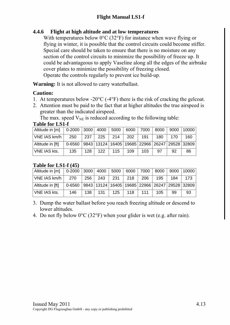
4.4.6 Flight at high altitude and at low temperatures
With temperatures below 0°C (32°F) for instance when wave flying or flying in winter, it is possible that the control circuits could become stiffer. Special care should be taken to ensure that there is no moisture on any section of the control circuits to minimize the possibility of freeze up. It could be advantageous to apply Vaseline along all the edges of the airbrake cover plates to minimize the possibility of freezing closed. Operate the controls regularly to prevent ice build-up.
Warning: It is not allowed to carry waterballast.
Caution: 1. At temperatures below -20°C (-4°F) there is the risk of cracking the gelcoat. 2. Attention must be paid to the fact that at higher altitudes the true airspeed is
greater than the indicated airspeed. The max. speed VNE is reduced according to the following table:
Table for LS1-f Altitude in [m] 0-2000 3000 4000 5000 6000 7000 8000 9000 10000
VNE IAS km/h 250 237 225 214 202 191 180 170 160
Altitude in [ft] 0-6560 9843 13124 16405 19685 22966 26247 29528 32809
VNE IAS kts. 135 128 122 115 109 103 97 92 86
Table for LS1-f (45) Altitude in [m] 0-2000 3000 4000 5000 6000 7000 8000 9000 10000
VNE IAS km/h 270 256 243 231 218 206 195 184 173
Altitude in [ft] 0-6560 9843 13124 16405 19685 22966 26247 29528 32809
VNE IAS kts. 146 138 131 125 118 111 105 99 93
3. Dump the water ballast before you reach freezing altitude or descend to lower altitudes.
4. Do not fly below 0°C (32°F) when your glider is wet (e.g. after rain).

Flight Manual LS1-f
Issued May 2011 4.14 Copyright DG Flugzeugbau GmbH - any copy or publishing prohibited
4.4.7 Flights in rain and thunderstorms
Rain drops, frozen fog and ice cover may change the wing section characteristics to such an extent, that flight characteristics will decrease. The minimun stall speed rises considerably. Therefore the approach speed must be increased.
Warning: Flights and especially winch launches in the vicinity of thunder storms must be avoided. In case of a lightning strike the composite structure may be damaged or destroyed. The sailplane is not equipped with a lightning protection system. 4.4.8 Cloud flying
Cloud flying is only permitted without waterballast! Take care to fly smoothly and coordinated. It is prohibited to use a spin as a method for loosing altitude in cloud. In case of emergency, pull out the airbrakes fully before exceeding a speed of 170 km/h and dive with max. 170 km/h (92 kts.) to leave the cloud. At higher speeds up to VNE pull out the airbrakes very carefully because of high aerodynamic and g-loads. You may extend the landing gear in addition to increase the sink rate.
Warning: Flight in thunderstorm clouds is prohibited. 4.4.9 Aerobatics
Aerobatic manoeuvres are prohibited

Flight Manual LS1-f
Issued May 2011 5.1 Copyright DG Flugzeugbau GmbH - any copy or publishing prohibited
50
70
90
110
130
150
170
190
210
230
250
50 70 90 110 130 150 170 190 210 230 250CAS km/h
IAS km/h
5 Performance
5.1 Airspeed indicator system calibration IAS= indicated airspeed CAS= calibrated airspeed
Caution: The airspeed indicator is to be connected to the static ports at the front fuselage.

Flight Manual LS1-f
Issued May 2011 5.2 Copyright DG Flugzeugbau GmbH - any copy or publishing prohibited
5.2 Stall speeds
The given speeds are the minimum achievable speeds during level flight in km/h and (kts.).
LS1-f: Airbrakes retracted: 70 � 65 km/h (38 � 35 kts.) without waterballast 80 � 75 km/h (43 � 40 kts.) with waterballast Airbrakes extended: 80 � 75 km/h (43 � 40 kts.) without waterballast 90 � 85 km/h (49 � 46 kts.) with waterballast
LS1-f (45): Airbrakes retracted: 70 � 65 km/h (38 � 35 kts.) without waterballast 85 � 80 km/h (46 � 43 kts.) with waterballast Airbrakes extended: 80 � 75 km/h (43 � 40 kts.) without waterballast 95 � 90 km/h (51 � 49 kts.) with waterballast
5.3 Demonstrated crosswing performance The demonstrated crosswind velocity is 15 km/h (8 kts) according to the airworthiness requirements.
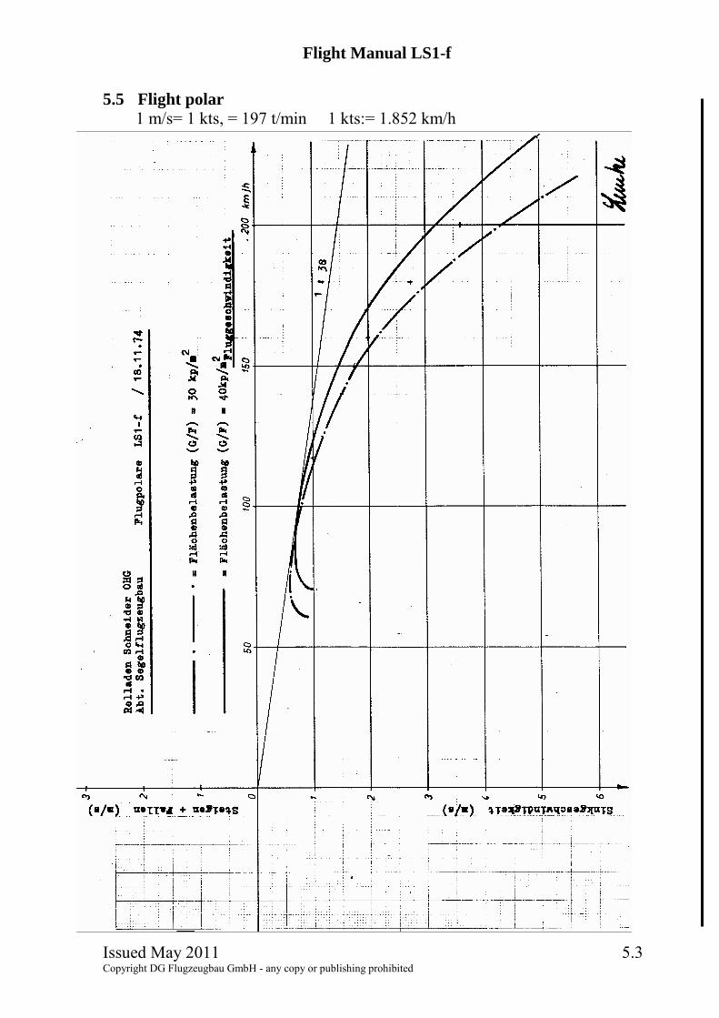
5.4 Gliding performance Wing loading kg/m² 32 35 40 45
Min. sink m/s 0,6 0,65 0,7 0,75 at V km/h 72 80 85 90
Max. L/D / 37 37,5 38 38,5 at V km/h 85 90 95 100
The wing fuselage joint, the horizontal tailplane - fin joint and the cutout for the talplane fixing nut should be taped and the aircraft thoroughly cleaned to obtain maximum performance.
The polars apply to a "clean" aircraft. With dirty wings, especially at the leading edge, or flight in rain the performance drops accordingly.
Flight Manual LS1-f
Issued May 2011 5.3 Copyright DG Flugzeugbau GmbH - any copy or publishing prohibited
5.5 Flight polar
1 m/s= 1 kts, = 197 t/min 1 kts:= 1.852 km/h

Flight Manual LS1-f
Issued May 2011 6.1 Copyright DG Flugzeugbau GmbH - any copy or publishing prohibited
6 Mass (weight) and balance
6.1 Introduction This section contains the payload range within which the sailplane may be safely operated. A procedure for calculating the in-flight C.G. is also provided.
A comprehensive list of all equipment available for this sailplane is contained in the maintenance manual.
6.2 Weighing procedures See maintenance manual LS1-f section 2. Datum: Wing leading edge at the root rib. Reference line: Lower side of aft fuselage boom horizontal.
6.3 Weighing record The result of each C.G. weighing is to be entered in section 6.8.4. If the min. cockpit load has changed this data is to be entered in the cockpit placard as well.
6.4 Basic empty mass and C.G. Actual data see section 6.8.4. With the empty weight C.G. and the cockpit loads within the limits of the table in section 2.3 of the MM, the in-flight C.G. limits will not be exceeded.
6.5 Mass of all non-lifting parts (WNLP) The max. mass of all non-lifting parts is 230 kg (507 lbs.). WNLP is to be determined as follows: WNLP = WNLP empty + cockpit load (pilots, parachute, baggage, trim ballast, removable items of equipment etc.). WNLP empty = Total empty weight incl. permanently installed equipment minus weight of the wings.
6.6 Max. mass (weight) Maximum take off weight and landing weight: Variant LS1-f: 390 kg (860 lbs.) Variant LS1-f (45): 439 kg (968 lbs.) Max. mass without waterballast: Maximum take-off and landing mass = WNLP + Wwings WNLP = Maximum mass of all non lifting parts (see above) Wwings = actual mass of the wings

Flight Manual LS1-f
Issued May 2011 6.2 Copyright DG Flugzeugbau GmbH - any copy or publishing prohibited
6.7 Useful loads (payload)
Max. payload without waterballast = max. weight without waterballast - empty weight
Max. payload with waterballast = max. weight with waterballast - empty weight
The data is recorded in section 6.8.5.
6.8 Loading chart 6.8.1 Cockpit load
Cockpit load see weighing report section 6.8.4. With lower pilot weight necessary ballast must be added in the seat. Ballast put on the seat (lead ballast cushion) must be fastened at the connections of the safety belts.
6.8.2 Baggage max. 12 kg (26.5 lbs) Heavy pieces of baggage must be secured to the baggage compartment floor. The added load in the fuselage must not exceed the max. payload without waterballast (W.B.) see weighing report section 6.8.4.
6.8.3 Waterballast in the wing tanks Max. capacity: Variant LS1-f: 90 kg (198 lbs.), (23.8 US.gal.) Variant LS1-f (45): 180 kg (198 lbs.), (17.6 US.gal.)
Warning: Filling the water ballast is only allowed with a filling system which enables determination of the exact amount of ballast filled, e.g. water gauge or calibrated canisters. Don�t try to fill more water into the tanks than the specified values. It is only allowed to fly with symmetric wing ballast!
The total amount of ballast is dependent on the empty mass and the fuselage load and can be determined from the tables in section 6.8.5.

Flight Manual LS1-f
Issued May 2011 6.3 Copyright DG Flugzeugbau GmbH - any copy or publishing prohibited
6.8.4 Weighing report (for section 6.3) Distances in mm, masses in kg -- 25.4 mm = 1 inch / 1 kg = 2.2046 lbs. Date of weighing:
Executed by:
Date of equipment list:
Empty mass
Empty mass C.G.
Max. mass without W.B.
Max. payload without W.B.
Max. mass with W.B.
Max. payload with W.B.
Min. cockpit load
Max.cockpit load
Inspector, signature, stamp

Flight Manual LS1-f
Issued May 2011 6.4 Copyright DG Flugzeugbau GmbH - any copy or publishing prohibited
6.8.5 Ballast chart (total ballast)
To determine the max. allowable total waterballast. Fuselage load = pilot + baggage etc. but without waterballast. All values in kg ( l ) 1 kg = 2.2046 lbs. 3.785 kg (l) = 1 US gal. a) Ballast chart (total ballast) LS1-f:
payload fuselage/ empty mass 200 205 210 215 220 225 230 235 240 245 250
60 179 174 169 164 159 154 149 144 139 134 12965 174 169 164 159 154 149 144 139 134 129 12470 169 164 159 154 149 144 139 134 129 124 11975 164 159 154 149 144 139 134 129 124 119 11480 159 154 149 144 139 134 129 124 119 114 10985 154 149 144 139 134 129 124 119 114 109 10490 149 144 139 134 129 124 119 114 109 104 99 95 144 139 134 129 124 119 114 109 104 99 94 100 139 134 129 124 119 114 109 104 99 94 89 105 134 129 124 119 114 109 104 99 94 89 84 110 129 124 119 114 109 104 99 94 89 84 79
Example: Empty mass 230 kg, Pilot + parachute 95 kg => max. amount of waterballast 65 kg, in case the wing tanks can take up this amount.

Flight Manual LS1-f
Issued May 2011 6.5 Copyright DG Flugzeugbau GmbH - any copy or publishing prohibited
b) Ballast chart (total ballast) LS1-f (45):
payload fuselage/ empty mass 228 230 232 234 236 238 240 242 244 246
60 151 149 147 145 143 141 139 137 135 133 65 146 144 142 140 138 136 134 132 130 128 70 141 139 137 135 133 131 129 127 125 123 75 136 134 132 130 128 126 124 122 120 118 80 131 129 127 125 123 121 119 117 115 113 85 126 124 122 120 118 116 114 112 110 108 90 1210 119 117 115 113 111 109 107 105 103 95 116 114 112 110 108 106 104 102 100 98 100 111 109 107 105 103 101 99 97 95 93 105 106 104 102 100 98 96 94 92 90 88 110 101 99 97 95 93 91 89 87 85 83
Example: Empty mass 230 kg, Pilot + parachute 95 kg => max. amount of waterballast 114 kg, in case the wing tanks can take up this amount.

Flight Manual LS1-f
Issued May 2011 7.1 Copyright DG Flugzeugbau GmbH - any copy or publishing prohibited
7 Sailplane and systems description
7.1 Introduction Section 7 describes the operation of the sailplane including its systems. M.M. = Maintenance manual Refer to section 9 "Supplements" for details of optional systems and equipment.
7.2 Airframe The LS1-f is a single-seater high performance glider with 15 m wingspan.
Construction: Wings GFRP-foam-sandwich-shell
Wing spars Double T-spar, GFRP-roving spar caps,
GFRP-foam-sandwich shear web Ailerons GFRP-shell Rudder GFRP-shell Horizontal stabilizer GFRP-foam sandwich-shell without spar Elevator GFRP -shell Fuselage GFRP-shell with GFRP bulkheads
Tailplane: T-Tail with conventional stabilizer-elevator and spring trim. Colours: All parts exposed to sunlight except for registration marks and anti-collision paint must be white.
7.3 Placards Airspeed indicator markings see section 2.3. Data placard, Checklist and limitation placards see section 2.16
ON at the master switch
OFF
at the waterballast handle
Further placards see next page.

Flight Manual LS1-f
Issued May 2011 7.2 Copyright DG Flugzeugbau GmbH - any copy or publishing prohibited
Placards cont.
All placards without given position must be glued next to the respective control handle.
7.4 Aileron control Activation via pushrods, connection with L�Hotellier connectors with additional securing device according to section 4.2.2 and L�Hotellier balls at wingside pushrods. Ailerons partly mass balanced.
7.5 Elevator control, trim Conventional tailplane, elevator activated via pushrods. Automatic coupling during assembly of horizontal tail, mass balance in the vertical control pushrod inside the fin. Trim: Spring trim sytem with handle at left hand cockpit wall.
7.6 Rudder Control Activation via steel cables, mass balance at rudder.

Flight Manual LS1-f
Issued May 2011 7.3 Copyright DG Flugzeugbau GmbH - any copy or publishing prohibited
7.7 Wheel brake
Activation via steel cable coupled to the airbrake control. The brake begins to function with airbrakes nearly fully extended. The wheel brake is an emergency brake and should be used only when necessary to minimize wear. Wheel with drum brake type Tost Liliput
7.8 Airbrakes Schempp-Hirth type airbrakes on upper wing surface. Activation via pushrods, connection with L�Hoteller swivel joints with additional securing device according to section 4.2.2 and L�Hotellier balls at wingside pushrods. Overcentre-locking in fuselage, spring mounted airbrake caps.
7.9 Waterballast System Waterbags, capacity: Variant LS1-f: 90 kg (198 lbs.), (23.8 US.gal.) Variant LS1-f (45): 180 kg (198 lbs.), (17.6 US.gal.) Dump valve on landing gear box. Dumping is via the landing gear box.
7.10 Cockpit Fiberglass shell. Controls for landing gear (black), trim (green) and divebrakes (blue) are located on the left side of the cockpit. Controls for tow release (yellow) and pedal adjustment (black) at left hand side of instrument panel; canopy emergency release and ventilation are located at right hand side of instrument panel. Canopy lock (red) on both sides of canopy. Water ballast valve control (black) located on right side of cockpit. Backrest adjustable at ground..
7.11 Canopy One piece hinged up front, assisted by a gas-strut. Instrument cover accommodates compass. Material Plexiglas clear or optionally light blue. Emergency release see section 7.20.
7.12 Tow hooks "Safety release Europa G72, G73 or G88" for winch- and aerotow installed near the C.G.. Additionally (Option TN59): "nose release E72, E75 or E85" installed in the fuselage nose, only for aerotow. Both hooks are operated by the same handle.

Flight Manual LS1-f
Issued May 2011 7.4 Copyright DG Flugzeugbau GmbH - any copy or publishing prohibited
7.13 Rudder pedal adjustment
Adjustment is possible in flight and on the ground. Release pressure of pedals and unlock pulling the black handle. Push pedals forward into desired position, using feet pressure. To move backwards pull pedals with handle into desired position. Release handle for locking.
7.14 Seat, back rest and safety harness The seat pan is removable. The backrest is adjustable on the ground. A cushion above the back rest acts as head rest. The LS1-f must be equipped with a 4 point safety harness fixed at the provided fixing points.
7.15 Instrument panel Fixed installation. Normally with hinged upper part, optionally fixed according to TM29. Up to 8 instruments plus radio may be installed. Max. mass installed in the upper part: 4 kg (8.8 lbs.).
7.16 Baggage compartment Max. load 12 kg (26.5 lbs) Heavy pieces of baggage must be secured to the baggage compartment floor. Otherwise load only soft and light items.
7.17 Oxygen system A fiberglas receptacle is installed in the right hand side of the main bulkhead for 3 or 4 Litre oxygen bottles of 100 mm (3.94 in) in diameter. Bottles must be fixed with the designated clamp (P/N.: 4R8-41c)
7.18 Landing gear Retractable landing gear, installed in a GFRP Box. The box is totally closed with landing gear up. Drum brake. Operating handle on left hand side. The landing gear may be retracted and extended at any speed up to VNE. A brisk movement of the handle facilitates retraction. Tyre: 4.00-4 Tost Aero 8pr Tyre pressure: 3,0 -3,5 bar (43.5 - 51 psi) Handle to the front: retracted Handle to the rear: extended

Flight Manual LS1-f
Issued May 2011 7.5 Copyright DG Flugzeugbau GmbH - any copy or publishing prohibited
7.19 Pitot-/Static pressure system
Pitot pressure port installed in fuselage nose (red), with optionally nose tow release (TN59) the pitot pressure port is installed in the fin. Static pressure ports at lower front fuselage (blue). Airspeed indicator and altimeter must be connected to these ports. Port for TE probe in the fin. Additional static ports in the aft fuselage and optionally in the upper front fuselage to connect variometers or gliding computers.
7.20 Canopy emergency release Check proper function of canopy locking and emergency release (not daily, but to be completed at minimum every 3 months): a) "Pilot" in seat, both canopy locking handles opened. One person at the
front end to lift the canopy from the fuselage. After pulling the emergency canopy release handle the canopy must be freely moveable at the front. With TN61-LS executed: The canopy must be lifted at the front by the spring at the hinge by about 30 mm <1.2 in.>.
b) After pulling the emergency canopy release handle the pilot pushes the canopy up at the rear to disengage the LS-Latch (Röger hook) from the spring on the fuselage.
c) Then the pilot lifts the canopy at the rear end up as far as possible, the person at the front end holds the canopy.
Caution: The person at the front end should not lift the canopy too far up. Otherwise this would unduly deform the spring of the LS-Latch (Röger hook) located at the fuselage. Note: b) and �Caution*� apply only if TN61-LS LS-Latch (Röger Hook) has been completed
Reinstalling the canopy: 2 persons are needed a) Pull the canopy hinge up to the open position. b) One person (at the front end) holds with one hand the emergency release
lock in open position and places the canopy with the other hand onto the hinge. The other person holds the canopy rear end so far up that it matches the canopy hinge. With TN61-LS executed: The spring fixed at the canopy must be inserted into the ring at the canopy lifting mechanism. When pressing down the canopy make sure that the spring doesn�t buckle.
c) The front person engages the canopy by turning the emergency release lock to the stop.

Flight Manual LS1-f
Issued May 2011 8.1 Copyright DG Flugzeugbau GmbH - any copy or publishing prohibited
8 Sailplane handling, care and maintenance
8.1 Introduction Section 8 contains manufacturer's recommended procedures for proper ground handling and servicing of the sailplane. It also identifies certain inspection and maintenance requirements which must be followed if the sailplane is to retain that new-plane performance and dependability. It is wise to follow a planned schedule of lubrication and preventive maintenance based on climatic and flying conditions encountered.
8.2 Inspection period, maintenance The "Instructions for continued airworthiness� (Maintenance manual) for the LS1-f have to be followed. Before each rigging all the connecting pins and bushes should be cleaned and greased. Once a year all the bearings and hinges should be cleaned and greased. See the lubrication schedule of the maintenance manual section 3.4. Each year the control surface displacements, adjustments and general condition must be checked. (See the maintenance manual section 3).
8.3 Alterations or repairs It is essential that the responsible airworthiness authority be contacted prior to any alterations on the aeroplane, to ensure that the airworthiness of the sailplane is not impaired. It is prohibited to perform alterations without approval of the airworthiness authority. The manufacturer will not be liable for the alteration or for damages resulting from changes in the characteristics of the aircraft due to alteration. So it is strongly recommended to perform no alterations which are not approved by the aircraft manufacturer. External loads such as external camera installations are to be regarded as alterations! Repair instructions can be found in the LS1-f maintenance manual section 10. No repairs should be carried out without referring to the manual.

Flight Manual LS1-f
Issued May 2011 8.2 Copyright DG Flugzeugbau GmbH - any copy or publishing prohibited
8.4 Tie Down, Parking
Use textile ropes or straps to tie down the wing tips. The fuselage should be tied down just ahead of the fin. Water ballast can be left in the wings for a few days only, but not when there is the possibility of freezing! On sunny days the canopy should be closed and covered.
Note: Longer parking with exposure to sun and humidity will cause premature ageing of the external surfaces of your sailplane. 8.5 Transport
It is recommended to carry this valuable sailplane in a factory recommended closed trailer. Approved fitting points: Wings:
1. Wing spar as close to wing rootrib as possible or a rootrib wing cradle. 2. A wing cradle at the taper change.
Horizontal tailplane: Cradles as desired Fuselage:
1. A felt lined fibreglass nose cap which does not extend over the canopy, secured to floor.
2. Fuselage dolly in front of the undercarriage or a support attached to the lift pins bushes, use plastic or brass pins.
3. Tail skid-well in trailer floor. Secure fuselage with a belt in front of the fin or hold it down with the trailer top (soft foam in top). All parts: All aircraft structures should not be subject to any unusual loads. With high temperatures that can occur inside trailers, these loads in time can warp any fibre reinforced plastic sailplane. The trailer should be well ventilated so as to prevent moisture build up which could result in bubbles forming in the gelcoat. A solar powered ventilator is recommended.

Flight Manual LS1-f
Issued May 2011 8.3 Copyright DG Flugzeugbau GmbH - any copy or publishing prohibited
8.6 Towing on the ground
Whenever possible tow at walking speed only. a) by towing at the tow hook using a rope with the standard double ring
approved for the ook. b) by using a tow bar which is fixed to the tail dolly and a wing tip wheel.
8.7 Cleaning and Care Remove any water from inside the airbrake boxes. Exterior surfaces of the fibre-reinforced plastic parts The surfaces are coated by a UP-gelcoat or Polyurethane paint (Option). This surface is protected by a hard wax coating which has been applied during production with a rotating disc ("Schwabbel" procedure). Do not remove the wax, because this would lead to shading, swelling and cracking of the surface. In general, the wax coat is very resistant. As soon as the wax coat is damaged or worn, a new coat has to be applied (see maintenance manual sect. 3.1). If you often leave your aircraft outside, this may be necessary every half year!
8.7.1 Hints for care - Wash the surface only with clean water using a sponge and chamois. - Adhesive remains of tape may be removed with petroleum ether (pure
petroleum spirit) which should be applied and removed immediately, otherwise this may lead to swelling of the gelcoat.
- More stubborn dirt which cannot be removed by washing may be cleaned off with silicone-free, wax containing car polishes (e.g. 1Z Extra, Meguiars in USA).
- Long-term dirt and shading can be removed by applying a new hard wax coat (see maintenance manual sect. 3.1).
- Never use alcohol, acetone, thinner etc.. Do not use detergents for washing!
- Protect the surface from intense sunlight. - Protect the aircraft from water and moisture. See sections 8.4 and 8.5. - Remove any water that has entered and allow the aircraft to dry out. - Never store your wet aircraft in a trailer.

Flight Manual LS1-f
Issued May 2011 8.4 Copyright DG Flugzeugbau GmbH - any copy or publishing prohibited
8.7.2 Plexiglas canopy
- Use clean water and a chamois for cleaning. - Stubborn dirt and small scratches can be removed by use of the "Schwabbel
procedure" (see maintenance manual sect. 3.1). 8.7.3 Metal parts
- Pins and bushes for rigging the aircraft are not surface protected and must be covered with grease at all times, see maintenance manual section 3.4.
- Other metal parts, especially the control stick and all handles should occasionally be preserved with metal polishs.

Flight Manual LS1-f
Issued May 2011 9.1 Copyright DG Flugzeugbau GmbH - any copy or publishing prohibited
9 Supplements
Section not effective