flight test overview for uas integration in the nas project
TRANSCRIPT
American Institute of Aeronautics and Astronautics
1
Flight Test Overview for UAS Integration in the NAS Project
James R. Murphy* NASA Ames Research Center, Moffett Field, CA, 94035
Peggy S. Hayes† and Sam K. Kim‡ NASA Armstrong Flight Research Center, Edwards, CA 93523
Wayne Bridges§ Flight Research Associates, Moffett Field, CA, 94035
Michael Marston** Jacobs Technology, Edwards, CA, 93523
The National Aeronautics and Space Administration is conducting a series of flight tests intended to collect data allowing for the flight of unmanned aircraft in the National Airspace System without the need for required waivers or exemptions from the Federal Aviation Administration. The most recent testing supported two separate test configurations. The first investigated the timing of detect and avoid alerting thresholds using a radar-equipped unmanned vehicle and multiple live intruders flown at varying encounter geometries. The second configuration included a surrogate unmanned vehicle (flown from a ground control station, with a safety pilot on board) flying a mission in a virtual air traffic control airspace sector using research pilot displays and Detect and Avoid advisories to maintain separation from live and virtual aircraft. The test was conducted over a seven week span in the summer of 2015. The data from over 100 encounter sorties will be used to inform the RTCA Phase 1 Detect and Avoid and Command and Control Minimum Operating Performance Standards, a document that is scheduled for release in 2016. Follow-on flight-testing is planned for the spring of 2016 to capture remaining encounters and support validation of the standards.
Nomenclature ADS-B = Automatic Dependent Surveillance - Broadcast C2 = Command and Control CPDS = Conflict Prediction and Display System DAA = Detect and Avoid DAIDALUS = Detect and Avoid Alerting Logic for Unmanned Systems GCS = Ground Control Station JADEM = Java Architecture for DAA Extensibility and Modeling LVC = Live, Virtual, Constructive describing the simulation environment MOPS = Minimum Operating Performance Standards NAS = National Airspace System TCAS = Traffic Alert and Collision Avoidance System UAS = Unmanned Aircraft System
* Project Engineer, Aviation Systems Division, MS 243-1, and AIAA Associate Fellow. † Deputy Chief Systems Engineer, Research and Engineering Directorate, and AIAA Senior Member. ‡ Project Engineer, Research and Engineering Directorate. § Air Traffic Controller (retired), Aviation Systems Division, MS 243-1 ** Test Director, Flight Operations Directorate.

American Institute of Aeronautics and Astronautics
2
I. Introduction HERE has been a tremendous increase in the interest of flying unmanned aircraft safely in the National Airspace System (NAS) in recent years.1 The application of unmanned aircraft to perform national security,
defense, scientific, and emergency management are driving the critical need for less restrictive access by Unmanned Aircraft Systems (UAS) to the NAS. UAS represent a new capability that will provide a variety of services in the government (public) and commercial (civil) aviation sectors. The growth of this industry has not yet been realized due in part to the lack of a common understanding of what is required to safely operate UAS in the NAS.2 In response, the Federal Aviation Administration (FAA) has been mandated to “develop a comprehensive plan to safely accelerate the integration of civil unmanned aircraft systems (UAS) into the national airspace system”.3 While the FAA has proposed a framework for rules to guide the introduction of small UAS (those under 55 pounds), existing Federal Aviation Regulations do not allow for full integration of unmanned aircraft into the NAS.4 In order to facilitate this integration, data supporting robust Detect and Avoid (DAA) and secure Command and Control (C2) capabilities need to be collected.5
In support of the community needs, the National Aeronautics and Space Administration (NASA) under the UAS Integration in the NAS Project (hereafter referred to as UAS-NAS Project) is investigating and integrating technologies that are intended to reduce technical barriers related to the safety and operational challenges associated with enabling routine UAS access to the NAS.6 The project is focusing on airspace integration procedures and performance standards to enable UAS integration in the air transportation system, covering DAA performance standards, C2 performance standards, and human systems integration. To support these research areas, the project has an integrated test and evaluation focus, providing the infrastructure for simulating traffic and collecting data. The test environment is comprised of air traffic control workstations, constructive and virtual aircraft simulators, UAS ground control stations (GCS) and live manned and unmanned aircraft that, operating together, provide researchers with a relevant NAS environment to test unmanned systems. Working closely with the researchers, the simulation and flight-test development team designs an environment that meets the needs for each specific data collection requirement. This paper describes the objectives and requirements of the integrated flight tests already conducted and presently planned by the UAS-NAS Project to collect the research data for the DAA, C2, and human systems focus areas. The designs and performance capabilities of the test infrastructure and data collection efforts are presented.
II. Background
A. UAS-NAS Project Overview With inputs from UAS stakeholders, including academia, government, and industry, the UAS-NAS Project was
formulated to address the need for routine access to the global airspace for all classes of UAS. Based upon that need, the Project identified the following goal: To provide research findings to reduce technical barriers associated with integrating UAS into the NAS utilizing integrated system level tests in a relevant environment.6
The project goal will be accomplished through the development of system-level integration of key concepts, technologies and/or procedures. In addition, these integrated capabilities will be demonstrated in an operationally relevant environment with the following objectives:
• Report research findings (including validated data, algorithms, analysis, and recommendations) to support key decision makers in establishing policy, procedures, standards and regulations, enabling routine UAS access in the NAS.
• Establish the infrastructure for the integrated test and evaluation environment for UAS Integration in the NAS simulations and flight demonstrations.
The UAS-NAS Project research is divided into three main technical subprojects, each leading respective research areas: Separation Assurance/Sense and Avoid†† Interoperability, Human Systems Integration, and Communication. Detect and Avoid (formally Sense and Avoid) is defined as “the capability of a UAS to remain well clear from and avoid collisions with, other airborne traffic”.7 The research conducted under this subproject focuses on the interoperability between two aspects of DAA, self-separation and collision avoidance. Collision avoidance is the maneuvering of one or more aircraft required to prevent an imminent near-midair collision. Self-separation is intended to address the ability of a pilot to “see and avoid” other aircraft with support from sensors and advisory algorithms without triggering collision avoidance maneuvers in either aircraft. In order to improve safe flight and
†† The Detect and Avoid nomenclature was adopted from the previously used Sense and Avoid after formulation of the Project, hence the old terminology usage here.
T
American Institute of Aeronautics and Astronautics
3
interaction of unmanned aircraft with air traffic in the NAS, the human systems integration subproject researchers are investigating the display of necessary and sufficient information to the UAS pilot in the ground control station. This information includes the display of proximal aircraft and several levels of DAA maneuver advisories and alerts. The Communication subproject research includes the investigation of terrestrial based communication network that integrates line-of-sight ground station antennas to enable non-satellite based beyond line-of-sight control of unmanned aircraft from the ground. The Communications effort includes the development of prototype radios to test the terrestrial link performance characteristics and the C2 performance standards. Integrating each of these research subproject concepts together, the integrated test and evaluation team handles the system requirements gathering and development of the integrated test infrastructure.
B. RTCA Minimum Operating Performance Standards (MOPS) RTCA (formally known as Radio Technical Commission for Aeronautics) was charted by the FAA to operate advisory committees that develop solutions to real-world air transportation problems.8 In order to safely integrate the multitude of UAS platforms into non-segregated airspace, the FAA and UAS stakeholders have determined that both a robust DAA and a robust and secure C2 Data Link capability need to be established. In response, the FAA established the Unmanned Aircraft Systems Integration Office to support integration of UAS safely and efficiently into the NAS. In addition, RTCA formed Special Committee 228 to develop the Minimum Operational Performance Standards (MOPS) for DAA equipment, with emphasis in an initial phase of standards development on civil UAS equipped to operate into Class A airspace under IFR flight rules. The Operational Environment for the Phase 1 MOPS is the transitioning of a UAS to and from Class A or special use airspace, traversing Class D and E, and perhaps Class G airspace. A second phase of MOPS development is envisaged to specify DAA equipment to support extended UAS operations in Class D, E, and perhaps G, airspace. Moreover, the UAS Integration Office is working closely with the UAS community to develop the MOPS for the C2 Data Link. An initial phase of development will provide standards for the C2 Data Link using L-Band Terrestrial and C-Band Terrestrial data links. A second phase of MOPS development is envisaged to provide standards for the use of SatCom in multiple bands as a C2 Data Link to support UAS. NASA is a key member of RTCA SC-228 and is a primary contributor to the C2 and DAA MOPS.
C. Flight Testing Overview To support the collection of data for the development of the RTCA
Phase 1 MOPS, the UAS-NAS Project has planned a series of human in the loop simulations as well as two flight tests, Integrated Flight Test 1 and 2. The flight testing events are designed to enable collection of data in a realistic operating environment, including the inherent uncertainties of real winds and on board sensors. However, since the testing includes the flight of unmanned aircraft, which cannot presently fly in the NAS without restrictions and waivers from the FAA, the integrated test team developed a distributed environment that combines live, virtual, and constructive (or background) traffic and intercept scenario to promote the safe testing of the concepts and technologies
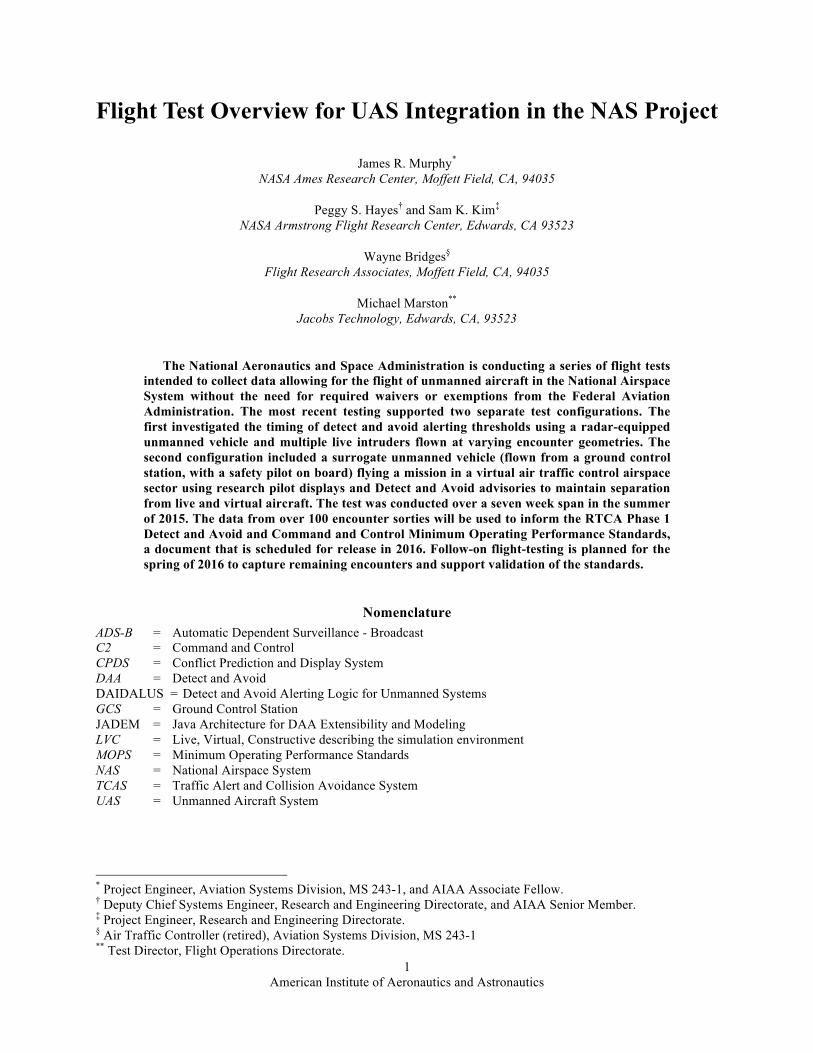
While the live, virtual, and constructive (LVC) components‡‡ of a test environment only encompass a portion of a full simulation or flight test, the test environment is widely known as an LVC. 9,10,11 Figure 1 shows the general usage of live, virtual and constructive assets contributing to the flight test environment. One of the significant aspects of the LVC environment is the support for integration of distributed assets to enable usage of equipment without the need for build-up of a local facility or deployment to a properly ‡‡ A “constructive” simulation generally has no interactive human involvement in simulated conditions. Instead, scenarios unfold using rule-based decisions that control the interactions between simulated actors. “Virtual” simulations involve human participants operating simulated systems (e.g. a pilot flying a flight simulator). A “live” test environment involves human participants operating real systems.
Figure 1. LVC Environment Concept of Operations. An LVC environment promotes the integration of multiple live and virtual data sources.

American Institute of Aeronautics and Astronautics
4
equipped test range. Instead the distributed LVC environment promotes a test-in-place concept that allows researchers and technologies to utilize assets in situ. A more detailed discussion of the UAS-NAS Project’s LVC environment is described by Murphy, et. al.12
For the UAS-NAS Project flight-testing, data collection is divided into two distinct test configurations. The first involves a UAS aircraft equipped with representative cooperative (e.g. GPS based ADS-B transponder) and non-cooperative sensors (e.g. on board due regard radar) and flown with live intruder aircraft against a series of different scripted encounters to test the timing of the alerting from DAA collision avoidance, self-separation algorithms and interoperability with certified traffic collision avoidance systems. All flights are conducted in restricted airspace in order to minimize risk. The second flight configuration integrates a surrogate UAS aircraft flown from a research ground control station equipped with pilot displays that provide advisories of potential conflicts and loss of separation. The ownship (UAS) aircraft is equipped with cooperative and non-cooperative sensors as required for the test and flown in special use airspace. The location of the ownship aircraft is translated into a virtual air traffic control airspace populated with a mix of live and virtual background and intruder aircraft, providing a realistic environment. The pilot of the ownship aircraft is given a virtual “mission” to perform, while using the DAA advisories to maintain well clear of the live and virtual aircraft.
In addition, the UAS-NAS Project is planning a “Capstone” event. During this demonstration, the UAS aircraft will be flown in the NAS (with any necessary waivers from the FAA) to demonstrate the performance of the DAA technologies. It is not intended for the Capstone event to collect data supporting the MOPS, but provide an opportunity for the industry to witness the Project’s testing and provide outreach to the general public.
III. Integrated Flight Test 1 Description The UAS-NAS Project requires several levels of flight test and simulation activities in order to collect the
appropriate data to support validation of the DAA and C2 MOPS. As such, the Integrated Flight Test (IFT1), internally referred to as Flight Test 313, had six primary research goals:
1. Validate results previously collected during project simulations with live data 2. Validate performance models previously used during project simulations with live data 3. Evaluate the Traffic Alert and Collision Avoidance System (TCAS) II/self-separation interoperability 4. Test a fully integrated system in a relevant live test environment 5. Collect data to inform final DAA and C2 MOPS 6. Reduce risk for follow-on flight testing
These goals were derived from previous UAS-NAS Project simulations supporting an evidenced based build-up
of the research. As described above, this flight test was divided into two distinct configurations (DAA Scripted Encounters and Full Mission), detailed in the sections below.
A. Detect and Avoid Scripted Encounters Configuration The Scripted Encounters Configuration generated data to evaluate the acceptability of the DAA alerts and
advisories. This configuration had the following high-level objectives: • Validate closest point of approach prediction accuracy and self-separation alerting logic in realistic
flight conditions • Validate self-separation trajectory model including maneuvers • Validate sensor and tracking models • Evaluate TCAS/self-separation interoperability
o Ownship TCAS/self-separation interaction o Compatibility with intruder’s TCAS
• Evaluate DAA performance in multi-threat encounters • Evaluate TCAS II as installed performance on a UAS • Qualitatively evaluate pilot impression of self-separation advisories • Inform final RTCA Phase 1 DAA and C2 MOPS
In order to achieve the required test points, the Scripted Encounters configuration utilized NASA’s Ikhana MQ-9
Predator-B aircraft as “ownship” aircraft. The Ikhana was equipped with a due regard radar, ADS-B, TCAS II, and a data fusion/tracker algorithm provided by Honeywell. Live intruders included a T-34C equipped with ADS-B and TCAS I, and a King Air, equipped with ADS-B and TCAS II. The Ikhana sensor data was transmitted to the ground
American Institute of Aeronautics and Astronautics
5
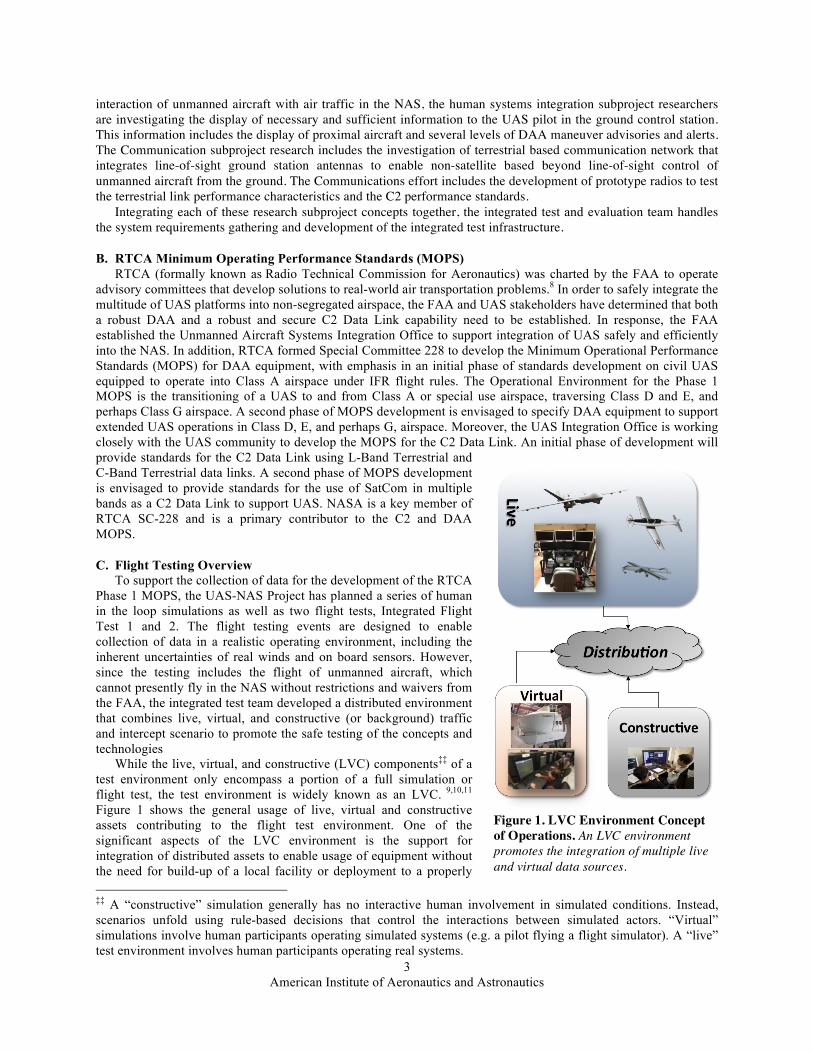
via a Ku-Band beyond line-of-sight link and sent to the DAA algorithms for analysis as shown in Figure 2. All test points were flown in the R-2515 restricted airspace near NASA Armstrong.
Three different DAA algorithms were tested (each during different test points). The first was the Conflict Prediction and Display System (CPDS) developed by General Atomics and Delft University of Technology, which provided its own display to the pilot.14 CPDS shows the ownship with proximal traffic and represents advisories as vertical and horizontal warning zones. Encounters tested with the CPDS included Ikhana climb/Intruder descent, Ikhana with multiple simultaneous intruders (illustrated in Figure 3), and close encounters with an intruder to test the DAA interoperability with TCAS alerting. Test points included the DAA algorithm fed by individual and fused sensor data.
The second DAA algorithm was the Java Architecture for DAA Extensibility and Modeling (JADEM) from NASA Ames Research Center15, which used the Vigilant Spirit Control Station’s (Vigilant Spirit) primary flight display to show advisories as a standalone unit next to the pilot. Vigilant Spirit is a fully implemented interface between a pilot in a GCS and an aircraft under control. It was developed by the Air Force Research Laboratory for flying UAS and is used as a test interface for the UAS-NAS Project.16 Tested encounters included “display scenarios” where the pilot of the Ikhana maneuvered the aircraft as directed by the DAA algorithm and “TCAS/self-separation interoperability scenarios” where the pilot does not maneuver the aircraft until the intruder’s TCAS has been alerted. The third algorithm was the Stratway+ algorithm from NASA Langley Research Center, which was originally developed to perform tactical resolution advisories for manned aircraft.17 Stratway+ presented its advisories on a standalone display next to the pilot via the Multi-Aircraft Control System (MACS) software.18 Test points were designed to validate closest point of approach predictions collected during earlier simulations using Stratway+.19 Specific encounters were also designed to operate on the edge of the alert threshold to collect data on the algorithm sensitivity to flight condition uncertainties. Additional test points included simultaneous multi-intruder encounters in both the vertical and horizontal domains and characterization of the due regard radar “edge” cases.
B. Full Mission Configuration The Full Mission configuration was designed to support the evaluation of the display of the DAA self-separation
alerts provided to the UAS pilot. This configuration had the following high-level objectives: • Evaluation of integrated self-separation algorithms, GCS traffic displays, and prototype C2 systems in a
realistic environment • Evaluate the effect of self-separation alerting and guidance information on pilots' ability to maintain
well clear • Gather objective and subjective pilot data to evaluate/validate well-clear definition • Analyze the performance of fourth generation C2 systems
Figure 3. Scripted Encounter Example. An example of multiple intruder encounter with an equipped UAS “ownship”.
Figure 2. High-Level Architecture for the Scripted Encounters. The system diagram showing the flight assets and LVC system components used for the Scripted Encounter testing. Only one DAA algorithm was run during any given test point.
American Institute of Aeronautics and Astronautics
6
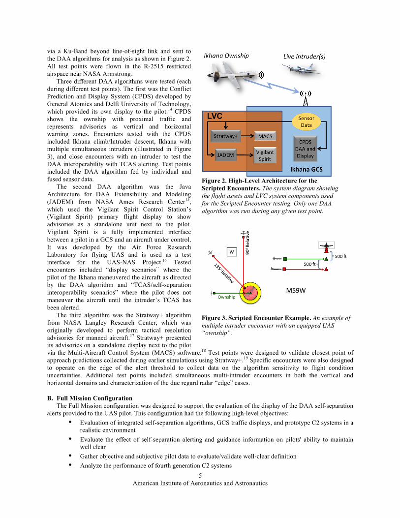
Figure 4 depicts a simplified diagram of the LVC
architecture used for the Full Mission configuration. The primary components included virtual air traffic control and constructive background traffic running at the NASA Ames Distributed Systems Research Laboratory, a live surrogate UAS aircraft controlled by the Vigilant Spirit at NASA Armstrong Research Ground Control Station Laboratory, DAA algorithms running in the NASA Armstrong LVC Laboratory, and live intruder aircraft.
The surrogate UAS aircraft (henceforth known as the “ownship”) was flown under an IFR flight plan in scenarios with live and virtual aircraft. The constructive background aircraft, enabled through the LVC environment, consisted of IFR and VFR traffic. Confederate controllers set up interaction between the background aircraft and the ownship to ensure that the DAA system provided advisories to the pilot based on the definition of Well Clear Volume parameters. In order for “well clear” to be violated all of the following conditions must be met:
• The horizontal closest point of approach or the current horizontal range is less than 0.8 NM • The time to horizontal closest point of approach is below 40 seconds • The time to co-altitude is below 40 seconds or the current vertical separation distance is below 500 ft.
The scenario for this test was a UAS aircraft controlled by a GCS stationed in southern California, with the aircraft deployed to scout for active wildfires in the San Francisco Bay area (see Oakland airspace descriptor below). The JADEM software provided the DAA algorithm for the test. The ownship was a T-34C aircraft flown as a surrogate UAS aircraft from a GCS using Vigilant Spirit at NASA Armstrong. The T-34C was equipped with ADS-B to enable cooperative sensing of other ADS-B equipped aircraft. The T-34C and live intruder aircraft flew in special use airspace near NASA Armstrong (R-2515), with the coordinates of the virtual Oakland Center sector (combined sectors 40/41) translated to that airspace. Constructive traffic and the confederate controllers were provided from a laboratory at NASA Ames interacting with the subject pilot and Vigilant Spirit via the distributed LVC system. Similar to the system used for the Scripted Encounters, the Full Mission system received data for the ownship and live intruder aircraft from the sensors on-board the T-34, sent to the ground via the C2 communication link. The virtual and live data were sent to and filtered by JADEM to determine which were candidates for processing by the algorithm and displayed to the pilot.
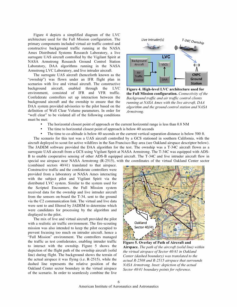
The mix of live and virtual aircraft provided the pilot with a realistic air traffic environment. The fire-scouting mission was also intended to keep the pilot occupied to prevent focusing too much on intruder aircraft, hence a “Full Mission” environment. The controllers managed the traffic as test confederates, enabling intruder traffic to interact with the ownship. Figure 5 shows the depiction of the flight path of the ownship aircraft (solid line) during flight. The background shows the terrain of the actual airspace it was flying (i.e. R-2515), while the dashed line represents the relative position of the Oakland Center sector boundary in the virtual airspace of the scenario. In order to seamlessly combine the live
Figure 5. Overlay of Path of Aircraft and Airspace. The path of the aircraft (solid line) within the virtual airspace of Sector 40/41 in Oakland Center (dashed boundary) was translated to the actual R-2508 and R-2515 airspace that surrounds NASA Armstrong. Inset: depiction of the actual Sector 40/41 boundary points for reference.
Figure 4. High-level LVC architecture used for the Full Mission configuration. Connectivity of the Background traffic and air traffic control clients running at NASA Ames with the live aircraft, DAA algorithm and the ground control station and NASA Armstrong.

American Institute of Aeronautics and Astronautics
7
and virtual traffic, the Oakland Center airspace (airways, sector boundaries) and virtual traffic were mapped into the R-2515 airspace.
Each pilot flew two “Fire Mission” scenarios flying the same path, but with slightly different encounter geometries. In each scenario, the pilot was shown either a basic display of information or an enhanced display (shown in Figure 6). The basic information consisted of only the identification of the intruder based on the DAA alerts, while the enhanced display showed additional intruder symbols and maneuver advisories in the form of fly/no-fly bands. These have been coined “omni-bands” since they provide advisories for all viable flight headings.
IV. Integrated Flight Test 1 Data In support of the Scripted Encounters, a total of 11 Integrated Flight Test 1 flights were conducted between 17 June 2015 and 24 July 2015. During those flights, 108 of the 120 planned encounters vignettes were flown with Ikhana as the ownship. A total of 42.8 gigabytes of data were collected with a total of 2376 data files. The Appendix provides a list of the data collected and a detailed description of the data can be found in the Data Management Plan.20 The data are under analysis by the DAA research teams and results will be published separately.
The Full Mission configuration was run from 10-12 August 2015, with 3 pilots evaluating the display of DAA alerts in a realistic environment. The initial test plan called for a total of 10 test subjects, however significant problems with the data collection were documented during the preliminary integration testing and could not be resolved completely as execution of the flight test commenced. The most significant issue was with the command and control of the T-34C used as the surrogate ownship aircraft. During certain specific maneuvers, latencies between the time a maneuver was selected in the Vigilant Spirit and the time it was received and performed by the T-34C auto-pilot were recorded to be over 10 seconds. While observed on occasion during the check-out flights, this was an issue with the second and third test subjects and was a primary reason for ending the data collection early.
In addition, significant data drop-out from the T-34C to the ground was observed. As seen in Figure 7, the telemetry from the ownship aircraft that was being transmitted via the C2 data link would occasionally drop for up to 60 seconds at a time. This could have been accepted if these data-drop instances occurred only while the aircraft was not under a test encounter. However, several occurrences while the aircraft was either preparing to maneuver or maneuvering due to a DAA advisory were observed.
Ultimately, the value of the data being collected was questionable and the data collection efforts were postponed. It was decided to move all remaining test points for the Full Mission configuration to the final integrated flight test to be conducted the following year.
Figure 7. Display of T-34 Surrogate ground track. Aircraft position reports from the telemetry data shown as squares depict significant data drop for the ownship aircraft.
Figure 6. “Enhanced” display of DAA to the pilot. This shows the expanded concept for display of DAA information to a pilot, including the “basic” information and additional maneuver advisories via the “omni-bands”, depicting clear of conflicting heading maneuvers
American Institute of Aeronautics and Astronautics
8
V. Integrated Flight Test 2 Description
Integrated Flight Test 2 (IFT2) provides the researchers with an opportunity to expand on the data collected during the first flight tests. Following IFT1, additional scripted encounters with different aircraft performance and sensors will be conducted. IFT2 is presently planned for Spring of 2016 to ensure collection of data to support the validation of the final RTCA Phase 1 DAA MOPS. There are five primary objectives associated with this goal:
• Evaluate the performance of the DAA system against cooperative and non-cooperative aircraft encounters
• Evaluate UAS pilot performance in response to DAA maneuver guidance and alerting with live intruder encounters
• Evaluate TCAS/DAA interoperability • Characterize the performance of the flight test environment • Demonstrate flight test environment readiness to support the Capstone flights/effort
This flight test series will focus on only the Scripted Encounters configuration, supporting the collection of data
to validate the interoperability of DAA and collision avoidance algorithms. For the Scripted Encounters, it is anticipated that the Ikhana will once again be ownship for the test. As before, the JADEM DAA algorithm will be tested along with an updated version of Stratway+ called DAIDALUS (Detect and Avoid Alerting Logic for Unmanned Systems).21 The advisories from the DAA algorithms as well as TCAS will be presented to the UAS pilot on a standalone display with the pilot maneuvering based on those advisories.
VI. Capstone Description
The Capstone demonstration, slated for summer 2016, is intended to provide a meaningful review of the technologies under research in the UAS-NAS Project. The purpose of the demonstration is to highlight the advancements in the state-of-the-art for safe UAS flight to industry and the general public with simultaneously activities at the four participating NASA Centers (Ames, Armstrong, Glenn, and Langley).
The plans call for the Ikhana to be flown out of NASA Armstrong and interact with live and virtual intruder aircraft. The JADEM DAA system will receive the ownship and intruder data and provide maneuver advisories to ensure the Ikhana remains well clear of all aircraft. At the same time, an aircraft installed with the prototype communication system will fly out of NASA Glenn and also interact with virtual aircraft. The position of the Glenn and virtual aircraft will be sent to the DAIDALUS DAA system running at NASA Langley using a prototype version of the C2 link meeting the Phase 1 MOPS requirements. All of these systems will be integrated using the UAS-NAS project LVC infrastructure.
VII. Conclusions Despite the problems incurred during the Full Mission portion of IFT1, the UAS-NAS project has successfully
collected significant data contributing to the Phase 1 DAA MOPS. Nearly all Scripted Encounter test points were run, with the data collected and archived by the UAS-NAS Project’s integrated test and evaluation team. While the Full Mission configuration experienced latency and control issues with the surrogate aircraft, the UAS-NAS project has documented the lessons learned and is applying those to reduce risk and ensure a successful execution of IFT2. Objectives and test requirements have been collected for IFT2 and Capstone and planning for both of those activities are ongoing.
Furthermore, the LVC test infrastructure, technologies, and techniques developed by the integrated test and evaluation team during conduct of IFT1 are anticipated to provide not only a foundation for the conduct of IFT2, but for future manned and unmanned aviation research. As such, the development team is documenting the LVC environment and its usage, as well as its interfaces to the client assets. This will be made available at the end of the UAS-NAS Project in September 2016.
As the UAS-NAS Project prepares for its final Human in the Loop simulations and IFT2, the DAA, Human Systems, and C2 researchers are working closely with the RTCA SC-228 stakeholders to ensure the correct data are collected moving towards successful Verification and Validation of the Phase 1 C2 and DAA MOPS.

American Institute of Aeronautics and Astronautics
9
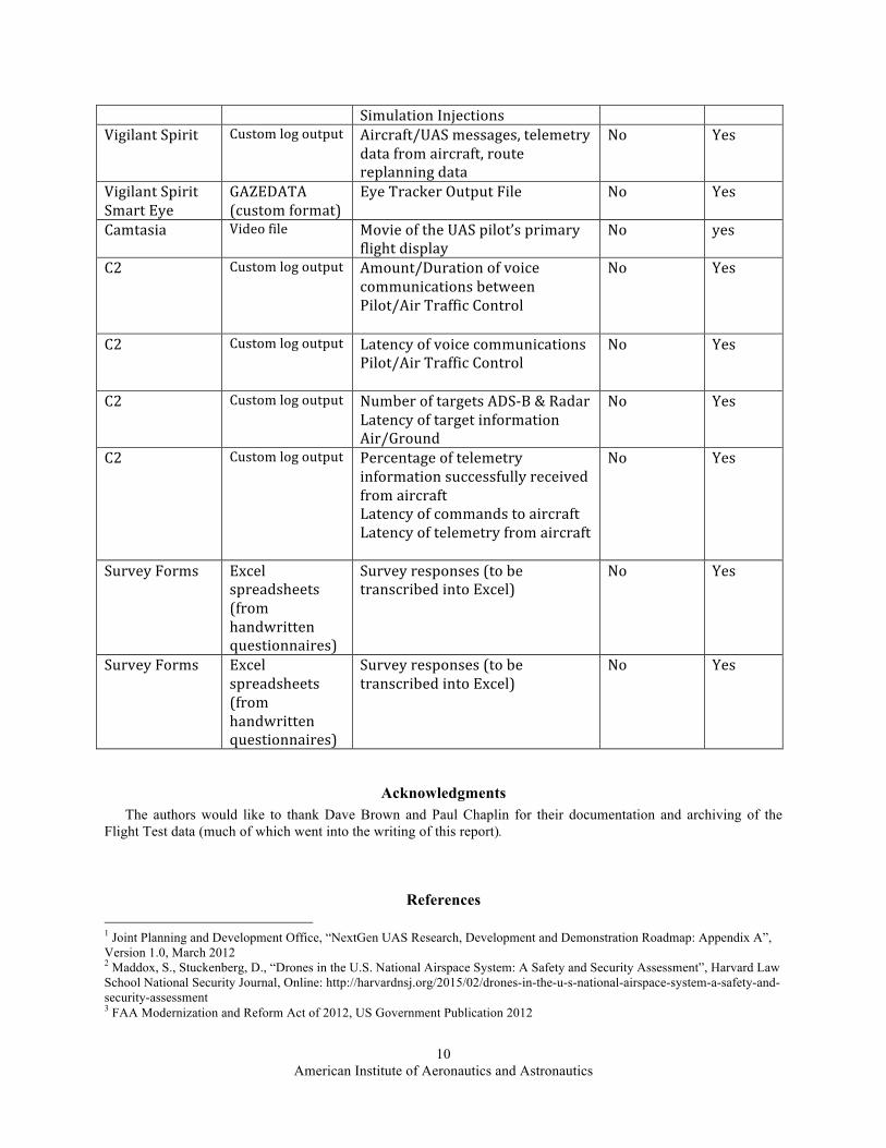
Appendix Listing and description of the data files captured during IFT1. System
Component File
Description Data Description Scripted
Encounters Full
Mission LVC Gateway (Data Logger)
Comma separated ASCII data (CSV)
Time and content of every message passed through the LVC Gateway, ASCII format
Yes Yes
LVC Gateway (Data Collector)
Binary data file (bin)
Time and content of every message passed through the LVC Gateway, binary format, used for playback
Yes Yes
JADEM CSV Ownship flight state data Yes Yes JADEM CSV Intruder state data (used for
analysis) Yes Yes
JADEM CSV Intruder state data (truth) Yes Yes JADEM CSV SAA threat results Yes Yes JADEM CSV SAA resolutions Yes Yes JADEM CSV SAA Release messages Yes Yes JADEM CSV Ownship constraints (from flight
intent) Yes Yes
JADEM CSV Encounter stats Yes Yes JADEM CSV Unresolved threats Yes Yes JADEM CSV Filtered conflicts (not analyzed) Yes Yes JADEM CSV Ownship path stretch metrics Yes Yes JADEM CSV Ownship resolution data Yes Yes JADEM CSV Ownship resolution attempts Yes Yes Stratway+ Custom log output Flight State Yes No Stratway+ Custom log output Customized Events Yes No Stratway+ Custom log output Pilot Inputs and Flight Deck Events Yes No Stratway+ Custom log output FMS Trajectories Yes No Stratway+ Custom log output GCS Pilot Inputs and Flight Deck
Events Yes No
Stratway+ Custom log output Closest Point of Approach Data Yes No Stratway+ Custom log output Stratway Input Data Yes No Stratway+ Custom log output Stratway Output Data Yes No Stratway+ Custom log output Stratway Band Data Yes No CPDS bin Internal DAA algorithm data Yes No Sense and Avoid Processor
Custom log output Ownship and intruder position data, ARINC 735B format
Yes No
C90 TPA-‐100B
Custom log output Time and content for each Traffic Alert and Resolution Advisory generated by the TCAS system onboard the Intruder aircraft
Yes Yes
Thales ADS-‐B ASTERIX CAT21 format
Aircraft position data Yes Yes
Vigilant Spirit Custom log output Chat logs, Standard Tasks logs, No Yes
American Institute of Aeronautics and Astronautics
10
Simulation Injections Vigilant Spirit Custom log output Aircraft/UAS messages, telemetry
data from aircraft, route replanning data
No Yes
Vigilant Spirit Smart Eye
GAZEDATA (custom format)
Eye Tracker Output File No Yes
Camtasia Video file Movie of the UAS pilot’s primary flight display
No yes
C2 Custom log output Amount/Duration of voice communications between Pilot/Air Traffic Control
No Yes
C2 Custom log output Latency of voice communications Pilot/Air Traffic Control
No Yes
C2 Custom log output Number of targets ADS-‐B & Radar Latency of target information Air/Ground
No Yes
C2 Custom log output Percentage of telemetry information successfully received from aircraft Latency of commands to aircraft Latency of telemetry from aircraft
No Yes
Survey Forms Excel spreadsheets (from handwritten questionnaires)
Survey responses (to be transcribed into Excel)
No Yes
Survey Forms Excel spreadsheets (from handwritten questionnaires)
Survey responses (to be transcribed into Excel)
No Yes
Acknowledgments The authors would like to thank Dave Brown and Paul Chaplin for their documentation and archiving of the
Flight Test data (much of which went into the writing of this report).
References 1 Joint Planning and Development Office, “NextGen UAS Research, Development and Demonstration Roadmap: Appendix A”, Version 1.0, March 2012 2 Maddox, S., Stuckenberg, D., “Drones in the U.S. National Airspace System: A Safety and Security Assessment”, Harvard Law School National Security Journal, Online: http://harvardnsj.org/2015/02/drones-in-the-u-s-national-airspace-system-a-safety-and-security-assessment 3 FAA Modernization and Reform Act of 2012, US Government Publication 2012

American Institute of Aeronautics and Astronautics
11
4 Federal Aviation Administration, Notice of proposed rulemaking: “Operation and Certification of Small Unmanned Aircraft Systems”, FAA-2015-0150; Notice No. 15-01 5 RTCA, “Terms of Reference, RTCA Special Committee 228, Minimum Performance Standards for Unmanned Aircraft Systems”, RTCA Paper No. 109-13/PMC-1089, May 20,2013 6 National Aeronautics and Space Administration, NASA Technology Development Project Plan, Unmanned Aircraft Systems (UAS) Integration in the National Airspace System (NAS), 31 January 2013 7 Federal Aviation Administration, “Sense and Avoid (SAA) for Unmanned Aircraft systems (UAS),” SAA Workshop Second Caucus Report, January 18, 2013 8 RTCA website: http://www.rtca.org, May 2015 9 Department of Defense: “Modeling and Simulation Master Plan”, DoD 5000.59P, Oct 1995 10 Henninger, Amy E., Cutts, Dannie, Loper, Margaret, et al, “Live Virtual Constructive Architecture Roadmap (LVCAR) Final Report”, Institute for Defense Analysis, Sept, 2008 11 Bezdek, W. J., Maleport, J., Olshon, R., “Live, Virtual & Constructive Simulation for Real Time Rapid Prototyping, Experimentation and Testing using Network Centric Operations,” AIAA 2008-7090, AIAA Modeling and Simulation Technologies Conference and Exhibit, August 2008 12 Murphy, J. Jovic, S., Otto, N., “Message Latency Characterization of a Distributed Live, Virtual, Constructive Simulation Environment,” AIAA Infotech@Aerospace Conference, January 2015 13 National Aeronautics and Space Administration, Integrated Test and Evaluation (IT&E) Flight Test 3 (FT3) Flight Test Plan Plan, Document No. FT3-FTP-01, May 2015 14 Suarez, B., Kirk, K., Theunissen, E., “Development, Integration and Testing od a Stand-Alone CDTI with Conflict Probing Support,” AIAA 2012-2487, AIAA Infotech@Aerospace, June 2012 15 Santiago, C., Mueller, E., “Pilot Evaluation of a UAS Detect-and-Avoid System’s Effectiveness in Remaining Well Clear,” Eleventh UAS/Europe Air Traffic Management Research and Development Seminar (ATM2015), June 2015 16 Feitshans, G. L., Rowe, A. J., Davis, J. E., Holland, M., and Berger, L., “Vigilant Spirit Control Station (VSCS)- “The Face of COUNTER”,” Proceedings of the AIAA Guidance, Navigation and Control Conference and Exhibition, Honolulu, Hawaii, AIAA 2008-6309, August 2008 17 Hagen, G., Butler, R., Maddalon, J., “Stratway: A Modular Approach to Strategic Conflict Resolution,” 11th AIAA Aviation Technology, Integration, and Operations (ATIO) Conference, Virginia Beach, VA, September 2011 18 Prevot, T., Smith, N., Palmer, E., Mercer, J., Lee, P., Homola, J., Callantine, T., “The Airspace Operations Laboratory (AOL) at NASA Ames Research Center,” AIAA 2006-6112, AIAA Modeling and Simulation Technologies Conference, August 2006 19 Chamberlain, J. P., Consiglio, M. C., Comstock, J. R., Ghatas, R. W., Munoz, C., “NASA Controller Acceptability Study 1 (CAS-1) Experiment Design and Initial Observations,” NASA TM 2015-218763 20 National Aeronautics and Space Administration, Flight Test 3 (FT3) Data Management Plan, Document No. FT3 IT&E DMP-001, 5 June 2015 21 Munoz, C., Narkawicz, A., Hagen, G., Upchurch, J., Dutle A., Consiglio, M., Chamberlain, J., “DAIDALUS: Detect and Avoid Alerting Logic for Unmanned Systems,” 34th Digital Avionics Systems Conference, Prague, Czech Republic, September 13–17, 2015