flo-tronic plus - united process...
TRANSCRIPT

Flo-Tronic Plus™
User Manual Revision 03

Flo-Tronic Plus Rev 03 Page 10
Copyright © 2013, Waukee Engineering., a member of United Process Controls. All rights to copy, reproduce and transmit are reserved
Manual #: 011 Initial Release: 12/21/2010 Rev No: 03 Date: 4/15/2013 COPYRIGHT No part of this publication may be reproduced, transmitted, transcribed, stored in a retrieval system, or translated into any language or computer language, in any form or by any means, electronic, mechanical, magnetic, optical, chemical, manual, or otherwise, without prior written permission of United Process Controls Inc.. DISCLAIMER: The Flo-Tronic PlusTM is to be used by the industrial operator under his/her direction. Waukee Engineering is not responsible or liable for any product, process, damage or injury incurred while using the Flo-Tronic PlusTM. United Process Controls Inc. makes no representations or warranties with respect to the contents hereof and specifically disclaim any implied warranties or merchantability or fitness for any particular purpose.
For assistance please contact:
United Process Controls Inc. TEL: +1-414-462-8200 • FAX: +1-414-462-7022 Toll free North America: +1-800-438-3347 [email protected] www.group-upc.com

Flo-Tronic Plus Rev 03 Page 11
Copyright © 2013, Waukee Engineering., a member of United Process Controls. All rights to copy, reproduce and transmit are reserved
1. WARNING Thank you for purchasing control equipment from Waukee Engineering a member of United Process Controls. We want your new control equipment to operate safely. Anyone who uses this equipment should read this publication (and any other relevant publications) before installing or operating the equipment. To minimize the risk of potential safety problems, you should follow all applicable local and national codes that regulate the installation and operation of your equipment. These codes vary from area to area and usually change with time. It is your responsibility to determine which codes should be followed, and to verify that the equipment, installation, and operation are in compliance with the latest version of these codes. At a minimum, you should follow all applicable sections of the National Fire Code, National Electrical Code, and codes of the National Electrical Manufacture’s Association (NEMA). There may be local regulatory or government offices that can also help determine which codes and standards are necessary for safe installation and operation. Equipment damage or serious injury to personnel can result from failure to follow all applicable codes and standards. We do not guarantee the products described in this publication are suitable for your particular application, nor do we assume any responsibility for you product design, installation, or operation. If you have any questions concerning the installation or operation of this equipment, or if you need additional information, please call us at 414-462-8200.
WARNING: Read this manual thoroughly before using Flo-Tronic. WARNING: This unit contains ESD (Electrostatic Discharge) sensitive parts and assemblies. Static control precautions are required when installing, testing, servicing or repairing this assembly. Component damage may result if ESD control procedures are not followed. If you are not familiar with static control procedures refer to an applicable ESD protection handbook. WARNING: Flo-Meter must be earth grounded. Ungrounded Flo-Meters may become a source of Ignition.

Flo-Tronic Plus Rev 03 Page 12
Copyright © 2013, Waukee Engineering., a member of United Process Controls. All rights to copy, reproduce and transmit are reserved
2. TABLE OF CONTENTS
1. WARNING ............................................................................................................................................................. 11
2. TABLE OF CONTENTS ............................................................................................................................................. 12
3. MANUAL OVERVIEW ............................................................................................................................................. 13
4. FLOW SENSOR INTRODUCTION ............................................................................................................................. 14
5. SPECIFICATIONS .................................................................................................................................................... 15
6. INSTALLATION AND WIRING ................................................................................................................................. 16
7. CALIBRATION AND FIELD SERVICE ......................................................................................................................... 19
8. MAINTENANCE ..................................................................................................................................................... 21
9. CALCULATIONS ..................................................................................................................................................... 22
10. TROUBLESHOOTING ............................................................................................................................................. 23
10. APPENDIX “A” - DRAWINGS .................................................................................................................................. 24
Flo-Tronic Plus Rev 03 Page 13
Copyright © 2013, Waukee Engineering., a member of United Process Controls. All rights to copy, reproduce and transmit are reserved
3. MANUAL OVERVIEW The Purpose of this Manual
Thank You for Purchasing a Flo-Tronic Plus™ Flow Sensor. This manual shows you how to install, wire and maintain Waukee’s Flo-Tronic Plus. It also helps you understand how to interface it to other devices in a control system. This manual contains important information and should be read and understood by all individuals who install, use or service this equipment.
Supplemental Manuals The Installation and Operation of Waukee Flo-Meters manual contain technical information as well as precautions about Waukee Flo-Meters.
Technical Support We strive to make our manuals the best in the industry. We rely on your feedback to let us know if we are reaching our goal. If you cannot find the solution to your particular application, or, if for any reason you need technical assistance, please call us at:
+1-414-462-8200 Toll free North America: +1-800-438-3347
Our technical support group will work with you to answer your questions. They are available Monday through Friday from 8:00 A.M. to 4:30 P.M. Central Standard Time. We also encourage you to visit our web site where you can find technical and non-technical information about our products and company.
http://www.waukeemeters.com http://www.group-upc.com
If you have a comment, question or suggestion about any of our products, services, or manuals, please e-mail or contact us by phone.
Conventions Used When you see the exclamation point icon in the left-hand margin, the paragraph to its immediate right will be a warning. This information could prevent injury, loss of property, or even death in extreme cases. Any warning in this manual should be regarded as critical information that should be read in its entirety. The word WARNING or CAUTION in boldface will mark the beginning of the text. When you see the “notepad” icon in the left-hand margin, the paragraph to its immediate right will be a special note.

Flo-Tronic Plus Rev 03 Page 14
Copyright © 2013, Waukee Engineering., a member of United Process Controls. All rights to copy, reproduce and transmit are reserved
4. FLOW SENSOR INTRODUCTION The Waukee Flo-Tronic™ utilizes a sensor to read the position of the float rod indicator on a Waukee Flo-Meter™. The unit provides both electrical and mechanical indication of flow. The unit is factory calibrated to provide linear and accurate flow measurement. If necessary, the Flo-Tronic may be “field calibrated”.
How it works
Magnet assembly attached to float rod of the Waukee Flo-Meter interacts with a magnetostrictive linear position sensor installed in Flo-Meter sensing head. A strain pulse is induced in a specially designed waveguide by the momentary interaction of two magnetic fields. One field comes from a moving magnet, which passes along the outside of the sensing tube, the other field from a current pulse launched along a wire inside the waveguide. The interaction between these two magnetic fields produces a strain pulse which travels at sonic speed along the waveguide, until the pulse is detected at the head of the transducer. The position of the moving magnet is precisely determined by measuring the elapsed time between the launching of the electronic pulse and the arrival of the strain pulse. As a result, accurate non-contact sensing of the Flo-Meter’s indicator is achieved. The indicator position is directly related to the Flo-Meter’s flow rate and is represented by a proportional analog electrical signal.
Model Explanation
FT M17
Size S17: S Gas (3” Scale) SF17: SF Liquid (3” Scale) M17: M1-7 (6” Scale) M811: M8-11 (6” Scale)
L13: L1-3 (9” Scale) L46: L4-6 (9” Scale) L79: L7-9 (9” Scale) L10: L10 (9” Scale)
Model

Flo-Tronic Plus Rev 03 Page 15
Copyright © 2013, Waukee Engineering., a member of United Process Controls. All rights to copy, reproduce and transmit are reserved
5. SPECIFICATIONS
± 0.4% FS + 1.6% Rd< 0.5% FS1:40 (2.5 … 100%)24VDC ± 10%75mACurrent: 4-20mA or 0-20mA Voltage: 0-10VDC or 2-10VDC
YES0.875mA1k Ohm
24VDC500 OhmSPST0.5A @ 30VDCNo power or alarm condition de-energize relay0°C to 65°C (32°F to 150°F)20 to 90% RH (non-condensing)-20°C to 65°C (-4°F to 150°F)IP 65Keep from corrosive gas and liquid
Relay OutputType
Contact RatingAlarm Logic
Analog Output
Current OutputOpen Circuit VoltageMax Load Impedance
Ranges Selectable
Short Circuit Protection
Min Load ImpedanceShort Circuit Current
Voltage Output
General SpecificationsOperation Specification
Electrical Power Operating VoltagePower Consumption
MeasurementAccuracy
RepeatabilityTurndown Ratio
Environment
Operating TempHumidity
Storage TempEnclosure Rating
Installation Location
Flo-Tronic Plus Rev 03 Page 16
Copyright © 2013, Waukee Engineering., a member of United Process Controls. All rights to copy, reproduce and transmit are reserved
6. INSTALLATION AND WIRING Flo-Meter Installation
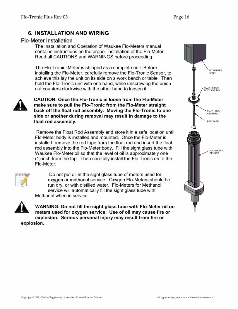
The Installation and Operation of Waukee Flo-Meters manual contains instructions on the proper installation of the Flo-Meter. Read all CAUTIONS and WARNINGS before proceeding.
The Flo-Tronic -Meter is shipped as a complete unit. Before installing the Flo-Meter, carefully remove the Flo-Tronic Sensor, to achieve this lay the unit on its side on a work bench or table. Then hold the Flo-Tronic unit with one hand, while unscrewing the union nut counters clockwise with the other hand to loosen it.
CAUTION: Once the Flo-Tronic is loose from the Flo-Meter make sure to pull the Flo-Tronic from the Flo-Meter straight back off the float rod assembly. Moving the Flo-Tronic to one side or another during removal may result in damage to the float rod assembly. Remove the Float Rod Assembly and store it in a safe location until Flo-Meter body is installed and mounted. Once the Flo-Meter is installed, remove the red tape from the float rod and insert the float rod assembly into the Flo-Meter body. Fill the sight glass tube with Waukee Flo-Meter oil so that the level of oil is approximately one (1) inch from the top. Then carefully install the Flo-Tronic on to the Flo-Meter.
Do not put oil in the sight glass tube of meters used for oxygen or methanol service. Oxygen Flo-Meters should be run dry, or with distilled water. Flo-Meters for Methanol service will automatically fill the sight glass tube with
Methanol when in service.
WARNING: Do not fill the sight glass tube with Flo-Meter oil on meters used for oxygen service. Use of oil may cause fire or explosion. Serious personal injury may result from fire or
explosion.
FLO-METER BODY
FLOAT ROD ASSEMBLY
FLO-TRONIC SENSOR
FLOAT STOP BODY O-RING
RED TAPE

Flo-Tronic Plus Rev 03 Page 17
Copyright © 2013, Waukee Engineering., a member of United Process Controls. All rights to copy, reproduce and transmit are reserved
Wiring Guidelines
Your company may have guidelines for wiring installation. If so, you should check those before you begin the installation. Here are some general things to consider:
• Use the shortest wiring route whenever possible. • Use shielded wiring for all signal wiring and ground the shield at the Field Device
end. DO NOT ground the shield at both the Flo-Tronic Sensor and Field Device. • Do not run the signal wiring next to large motors, high current switches, or
transformers. This may cause noise problems. • Route the wiring through an approved cable housing to minimize the risk of
accidental damage. Check local and national codes to choose the correct method for your application.
• Be sure to leave enough slack in the cables to allow easy removal of the Flo-Tronic from the Flo-Meter for maintenance. If seal tight or similar conduit is used, be sure to provide an adequate loop of conduit for maintenance access.
Wiring Connections
All wiring connections are located inside the main box. To access the wiring terminals remove the (4) four screws located on the front of the box and remove the cover.
CAUTION: To reduce the risk of electrical shock and also to prevent damage to the Flo-Tronic and the Field Device. It is advised to turn off the supply power to the Flo-Tronic and Field Device before connecting or disconnecting any wires.
WARNING: Any electrical or mechanical modification to this equipment without prior written consent of United Process Controls will void all warranties, may result in a safety hazard, and may void the CE listing.
Use 18-22AWG shielded cable for the signal wiring. It is recommended to run all signal wires in a separate steel conduit. The shield wire should only be connected at the Field Device end. Do not connect shield wire on both
ends.
Circuit Protection The Flo-Tronic is equipped with built-in over-voltage and short circuit protection. The unit may require recycling of power to reset once the fault condition is removed.
Flo-Tronic Plus Rev 03 Page 18
Copyright © 2013, Waukee Engineering., a member of United Process Controls. All rights to copy, reproduce and transmit are reserved
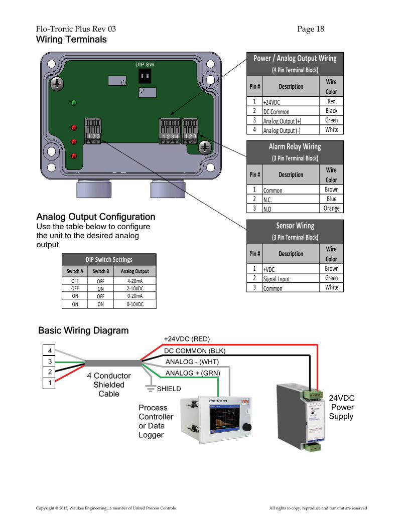
Wiring Terminals
Basic Wiring Diagram
24VDC Power Supply
+24VDC (RED)
ANALOG - (WHT)
ANALOG + (GRN) 4 Conductor Shielded
Cable
DC COMMON (BLK) 4
3
2
1
1 +24VDC Red2 DC Common Black3 Analog Output (+) Green4 Analog Output (-) White
Pin # Description
Power / Analog Output Wiring (4 Pin Terminal Block)
Wire Color
1 +VDC Brown2 Signal Input Green3 Common White
Pin # Description
Sensor Wiring (3 Pin Terminal Block)
Wire Color
Process Controller or Data Logger
OFF OFF 4-20mAOFF ON 2-10VDCON OFF 0-20mAON ON 0-10VDC
Switch A Switch B
DIP Switch SettingsAnalog Output
SHIELD
1 Common Brown2 N.C. Blue3 N.O Orange
Pin # Description
Alarm Relay Wiring (3 Pin Terminal Block)
Wire Color
1 2 3 1 2 3 4 1 2 3
Analog Output Configuration Use the table below to configure the unit to the desired analog output
DIP SW

Flo-Tronic Plus Rev 03 Page 19
Copyright © 2013, Waukee Engineering., a member of United Process Controls. All rights to copy, reproduce and transmit are reserved
Alarm Relay Wiring
The Flo-Tronic Plus includes an alarm relay, on power up the relay is energized to indicate that the unit has power. The relay will de-energize under the following alarm conditions:
• Loss of Power • Loss of Sensor Signal • Over Temperature Condition • Output Wiring Problem
CAUTION: Relay is for use with 30VDC or less ONLY!!! Use of any other voltage may result in damage to unit and poses a potential fire risk.
WARNING: An external relay must be used if connecting alarm contacts to a load over 0.5 Amps. Use of alarm contact with loads over 0.5 Amps will result in relay failure and poses a potential risk of fire.
7. CALIBRATION AND FIELD SERVICE The Flo-Tronic Plus output signal is calibrated at the factory and should be received calibrated, but in some cases the unit may require field calibration of the electronics. If you find that the analog output signal is not correct in relation to the indicated flow, you can recalibrate the output by the adjustment of the “Zero” and “Span” potentiometers located inside the sensor box.
CAUTION: Do not turn potentiometers excessively as these adjustments are sensitive.
SPAN
ZERO
+ Lead from DMM
- Lead from DMM
1 2 3 1 2 3 4 1 2 3

Flo-Tronic Plus Rev 03 Page 20
Copyright © 2013, Waukee Engineering., a member of United Process Controls. All rights to copy, reproduce and transmit are reserved
Measurement of Ouput Signal The best way to measure the output signal is to disconnect the unit from the field device and connect a multi-meter across terminals 3&4. Set the multi-meter to measure the correct signal the unit is setup for.
If you are unsure what the output signal is, refer to “Analog output configuration” located on page 8.
Adjustment of Output Signal
This procedure requires the ability to move the float rod from 0 “Zero” flow to 100% “Full Scale” flow. There are two methods to achieve this.
Method 1
Remove the Flo-Tronic and float rod assembly from the Flo-Meter and manually move the float rod assembly to the required position for calibration. Refer to page 6 of this manual for removal and installation. This is the preferred method of Calibration of the Flo-Tronic.
CAUTION: Make sure supply fluid to Flo-Meter has been SHUT-OFF before removing the Flo-Tronic from the Flo-Meter. Failure to do so may result in accidental death or explosion.
Method 2
If the equipment and process allows this, the float rod assembly can be moved to the required position for calibration by shutting off the fluid valve for zero flow and opening the fluid valve to full open for full flow.
WARNING: Depleting or over-gassing of equipment that the Flo-Meter is connected to may produce a hazardous condition, check with all personnel before attempting this method of calibration. Waukee is not responsible for any damages that may occur using this method.
To adjust the Zero (0%), the float rod should be at the bottom or zero flow position. Then adjust the “Zero” pot until the signal is correct for the selected analog output. This will be 4mA for 4-20mA, 0mA for 0-20mA, 2V for 2-10VDC and 0V for 0-10VDC
To adjust the Span “Full Scale Flow”, the float rod will now need to be adjusted to Full scale (100%). Then adjust the “Span” pot until the signal is correct for the selected analog output. This will be 20mA for a current output or 10VDC for a voltage output.
Flo-Tronic Plus Rev 03 Page 21
Copyright © 2013, Waukee Engineering., a member of United Process Controls. All rights to copy, reproduce and transmit are reserved
8. MAINTENANCE The Flo-Tronic is a magnetic based sensor which is unaffected by dirt. The dampening oil can be soiled to the point that it is not possible to visually read the flow on the Flo-Meter and the unit will still accurately determine the position of the float rod assembly. The Flo-Meter is a mechanical device that requires regular maintenance in order to maintain accuracy. All Flow Meters are susceptible to dirt affecting its accuracy. Although not all manufactures have a means to gauge when the Flo-Meter requires maintenance. Waukee Flo-Meters on the other hand have a built in indication when the Flo- Meter requires maintenance, which is the dampening oil. When the oil becomes soiled it is indication maintenance on the Flo-Meter is needed. The frequency of maintenance intervals will vary depending on the cleanliness of the gas being used. To replace the oil will require the removal of the Flo-Tronic; refer to the installation section of this manual for instructions. Also during these maintenance intervals it is recommended that all gaskets and o-rings are inspected for signs of wear or damage. Replace worn or damaged seals. Gasket kit sets are available from Waukee if needed.

Flo-Tronic Plus Rev 03 Page 22
Copyright © 2013, Waukee Engineering., a member of United Process Controls. All rights to copy, reproduce and transmit are reserved
9. CALCULATIONS Determine output for a given flow rate
1. First determine the % of scale represented by:
_Actual Flow (cfh) _ Full Scale Flow (cfh)
2. Then the Output is calculated by:
For 4-20mA mA = (% of Scale x 16) + 4 For 0-20mA mA = % of Scale x 20 For 2-10VDC VDC = (% of Scale x 8) + 2 For 0-10VDC VDC = % of Scale x 10
Determine the flow rate from the output
1. First determine % of Full Scale: mA – 4 16
0-20mA Range = mA 20
0-10VDC Range = VDC 10
2-10VDC Range = VDC-2 8
2. Then Actual Flow is calculated by:
Actual Flow = % of Full Scale x Full Scale Flow
% of Scale =
4-20mA Range =
Example 1: Scale Plate is 750CFH Indicated Flow is 500CFH Output range = 4-20mA 500 750 (.6666 x 16)+4 = 14.65mA
= .6666
Example 2: Find the flow rate for a 4-
20mA signal of 12.00mA and a Flow Meter Scale of 1000CFH
12 – 4 16 .5 x 1000 = 500CFH
= .5 or 50%

Flo-Tronic Plus Rev 03 Page 23
Copyright © 2013, Waukee Engineering., a member of United Process Controls. All rights to copy, reproduce and transmit are reserved
10. TROUBLESHOOTING Diagnostic Lights
The Flo-Tronic has a comprehensive diagnostic system. The diagnostic lights are displayed on the front panel of the unit. PWR - The Power LED indicates when power is
applied. SEN - The Sensor LED indicates when Sensor
Signal is Lost OUT – The Output LED indicates when there is a
problem with the output signal Current mode = Output Open (No Load)
or load resistance too high
Voltage mode = Output shorted or input resistance too low
TEMP – The TEMP LED indicates when unit electronics (IC) temperature is in excess of
185°F; unit will not function until temperature is below 185°F
PWR LED not Illuminated1. Check for 24VDC power at terminals 1 and 2 2. Make sure power supply is not over loaded
SENSOR LED Illuminated1. Check wiring at terminals 1,2,3 of sensor TB 2. Check for cut or damaged sensor cable
OUTPUT LED Illuminated1. Check wiring at terminals 3 & 4 2. Check wiring at Field device 3. Ensure unit is configured for correct output signal
TEMP LED Illuminated 1. Shield device from sources of heat
DiagnosticsDescription Corrective Actions
Flo-Tronic Plus Rev 03 Page 24
Copyright © 2013, Waukee Engineering., a member of United Process Controls. All rights to copy, reproduce and transmit are reserved
10. APPENDIX “A” - DRAWINGS On Demand

Flo-Tronic Plus Rev 03 Page 25
Copyright © 2013, Waukee Engineering., a member of United Process Controls. All rights to copy, reproduce and transmit are reserved
Reach us at www.group-upc.com
United Process Controls brings together leading brands to the heat treating industry including Waukee Engineering, Furnace Control, Marathon Monitors and Process-Electronic. We provide prime control solutions through our worldwide sales and services network with easy-to-access local support.
WAUKEE ENGINEERING COMPANY, INC. A member of United Process Controls 5600 West Florist Avenue, Milwaukee, WI 53218, U.S.A. Phone: +1-414-462-8200 Fax: +1-414-462-7022 E-mail: [email protected]