floating point multipliers: simulation & synthesis using...
TRANSCRIPT
Floating Point Multipliers: Simulation & Synthesis Using VHDL
By:
Raj Kumar Singh - B.E. (Hons.) Electrical & Electronics Shivananda Reddy - B.E. (Hons.) Electrical & Electronics
BITS, PILANI

Outline
Introduction - Multipliers
- VHDL & Design Flow
Various Architectures (Multipliers) -Simulation
-Synthesis
-Analysis
Conclusion
Real Numbers
Numbers with fractions
3/5 , 4/7
Pure binary
1001.1010 = 24 + 20 +2-1 + 2-3 =9.625
Fixed point
Very limited
Moving or floating point
(almost universal)
Widely used in computations

Which base do we use?
Decimal: great for humans, especially when doing arithmetic
Hex: if human looking at long strings of binary
numbers, its much easier to convert to hex and look 4 bits/symbol Not good for arithmetic on paper
Binary: what computers use; computers do +, -, *, / using this only To a computer, numbers always binary Regardless of how number is written:
32ten == 3210 == 0x20 == 1000002 == 0b100000
Floating Point :Overview
Floating point representation Normalization
Overflow, underflow
Rounding
Floating point addition
Floating point multiply

Floating Point (IEEE-754)
use a fixed number of bits
Sign bit S, exponent E, significand F
Value: (-1)S x F x 2E
IEEE 754 standard
Size Exponent Significand Range
Single precision 32b 8b 23b 2x10+/-38
Double precision 64b 11b 52b 2x10+/-308
S E F
Normalization
FP numbers are usually normalized i.e. exponent is adjusted so that leading bit (MSB) of
mantissa is 1
Example - Scientific notation where numbers are normalized to give a single digit before the decimal point
e.g. 3.123 x 10³
Because it is always 1, there is no need to store it
FP Overflow / Underflow
FP Overflow Analogous to integer overflow
Result is too big to represent
FP Overflow Result is too small to represent
Means exponent is too small (too negative)
Both raise Problems, thus need extra Care on their Occurrences in IEEE754

FP Rounding
Rounding is important
Small errors can save the huge storage
FP rounding hardware helps
Finally, keep sticky bit that is set whenever „1‟ bits are “lost” to the right
Differentiates between 0.5 and 0.500000000001
So the rounding can save a huge Memory, of course the price is Accuracy, But that can be paid

Base 2 : Representation
Number Base B B symbols per digit:
Base 10 (Decimal): 0, 1, 2, 3, 4, 5, 6, 7, 8, 9 Base 2 (Binary): 0, 1
Number representation:
d31d30 ... d1d0 is a 32 digit number
value = d31 B31 + d30 B30 + ... + d1 B1 + d0 B0
Binary: 0,1 (In binary digits called “bits”)
0b11010 = 1 24 + 1 23 + 0 22 + 1 21 + 0 20 = 16 + 8 + 2 = 26
Here 5 digit binary # turns into a 2 digit decimal #
#s often written
0b…
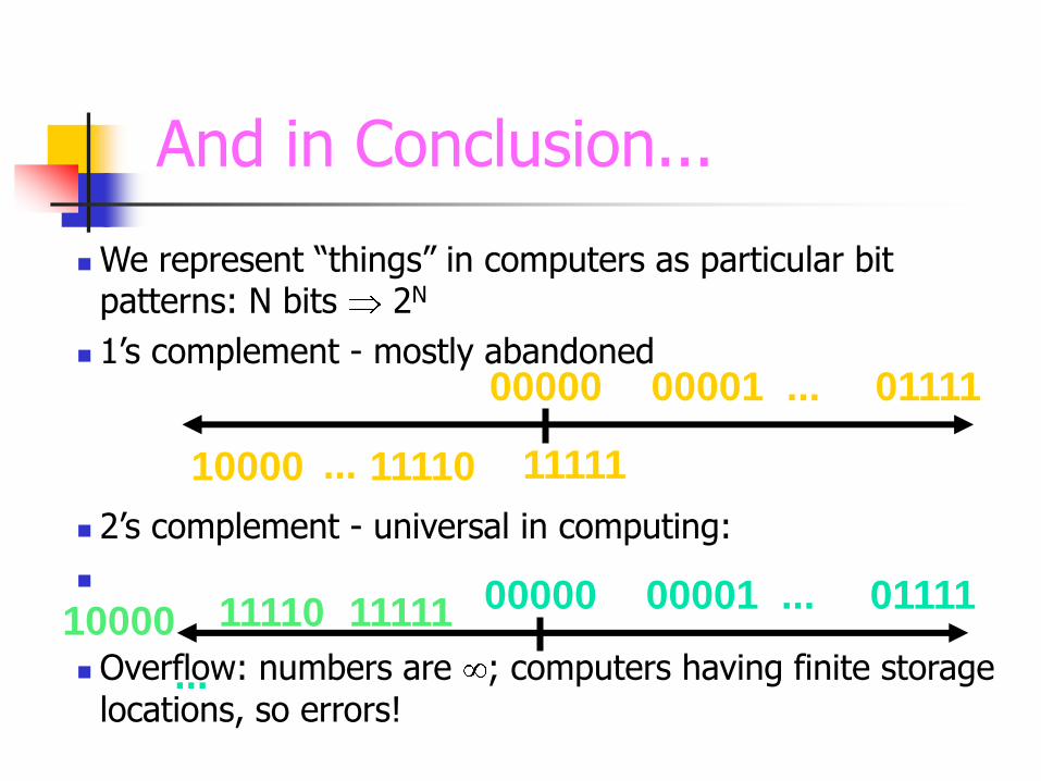
And in Conclusion...
We represent “things” in computers as particular bit patterns: N bits 2N
1‟s complement - mostly abandoned
2‟s complement - universal in computing:
Overflow: numbers are ; computers having finite storage locations, so errors!
00000 00001 01111 ...
11111 11110 10000 ...
00000 00001 01111 ... 11111 11110 10000
...

VHDL Language
Hardware Description Language (HDL) High-level language for to model, simulate, and
synthesize digital circuits and systems.
History 1980: US Department of Defense Very High Speed
Integrated Circuit program (VHSIC) 1987: Institute of Electrical and Electronics Engineers
ratifies IEEE Standard 1076 (VHDL‟87) 1993: VHDL language was revised and updated
Verilog is the other major HDL Syntax similar to C language

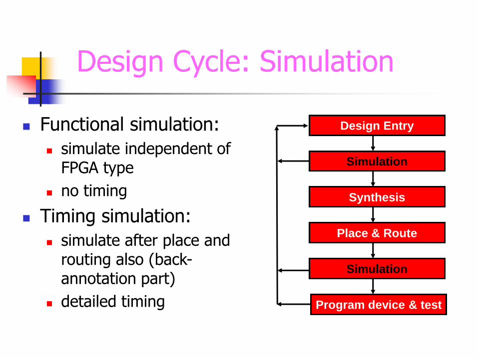
Design Cycle: Simulation
Functional simulation:
simulate independent of FPGA type
no timing
Timing simulation:
simulate after place and routing also (back-annotation part)
detailed timing
Design Entry
Simulation
Synthesis
Place & Route
Simulation
Program device & test
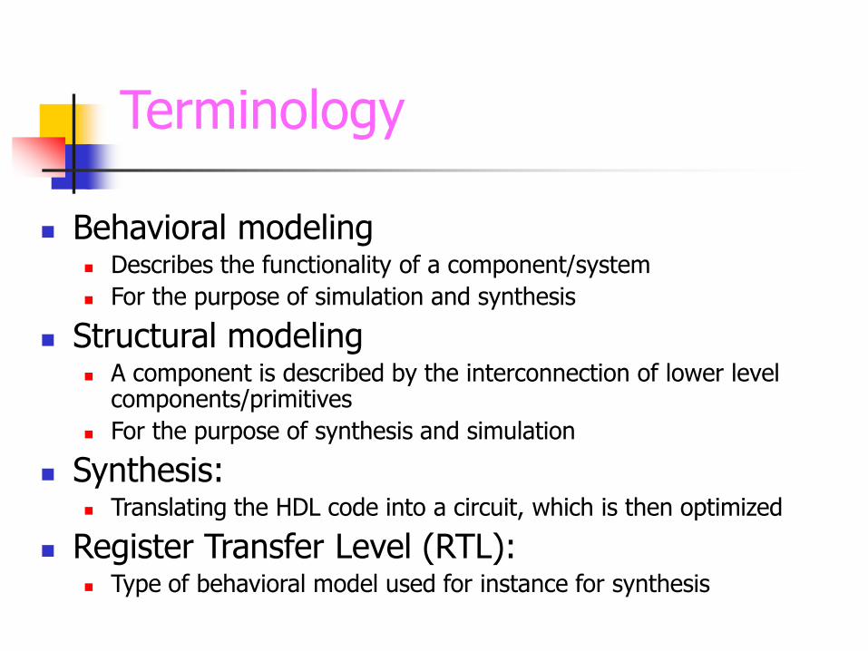
Terminology
Behavioral modeling Describes the functionality of a component/system
For the purpose of simulation and synthesis
Structural modeling A component is described by the interconnection of lower level
components/primitives
For the purpose of synthesis and simulation
Synthesis: Translating the HDL code into a circuit, which is then optimized
Register Transfer Level (RTL): Type of behavioral model used for instance for synthesis

RTL Synthesis
Input is RTL code
Compilation & translation Generates technology independent netlist
RTL schematic (HDL code analysis)
Technology mapping Mapping to technology specific structures:
Look-up tables (LUT)
Registers
RAM/ROM
DSP blocks
Other device specific components/features
Logic optimization Implementation analysis (technology view)
Design Entry
Simulation
Synthesis
Place & Route
Simulation
Program device & test
Digital Circuits and VHDL Primitives
Most digital systems can be described based on a few basic circuit elements:
Combinational Logic Gates:
NOT, OR, AND
Flip Flop
Latch
Tri-state Buffer
Each circuit primitive can be described in VHDL and used
as the basis for describing more complex circuits.

What is an SOC?
System-on-a-chip, System LSI, System-on-Silicon,
- Hardware
Analog: ADC, DAC, PLL, Tx, Rx, RF Devices
Digital: Processor, Memory, Interface, Accelerator,
Multiplier, Adder etc…
Software
OS
Application
What are the differences from an ASIC?
Traditional ASIC Design Flow
Specification Development
RTL Code Development
Functional Verification (Simulation)
Floor-planning, Synthesis, DFT
Fault Coverage Analysis
Timing Verification
Floor-planning, Placement and Route
Prototyping, Testing, and Characterization
Functional Verification Models Levels
Functional
Behavioral
RTL
Logic
Gate
Switch
Circuit
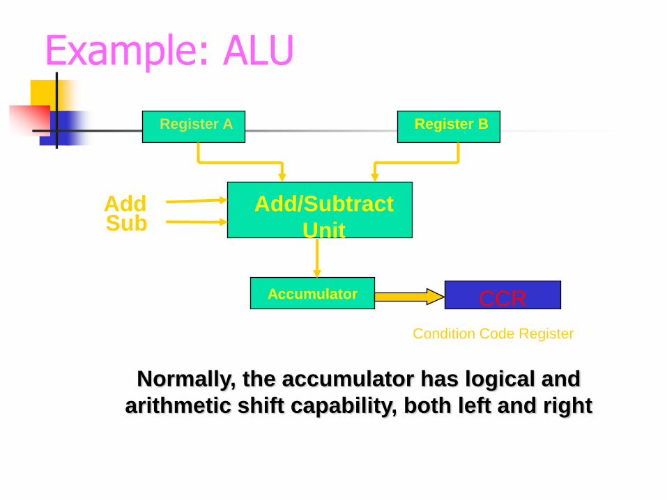
Example: ALU
Add Sub
Register A
Add/Subtract
Unit
Register B
Accumulator CCR
Condition Code Register
Normally, the accumulator has logical and
arithmetic shift capability, both left and right
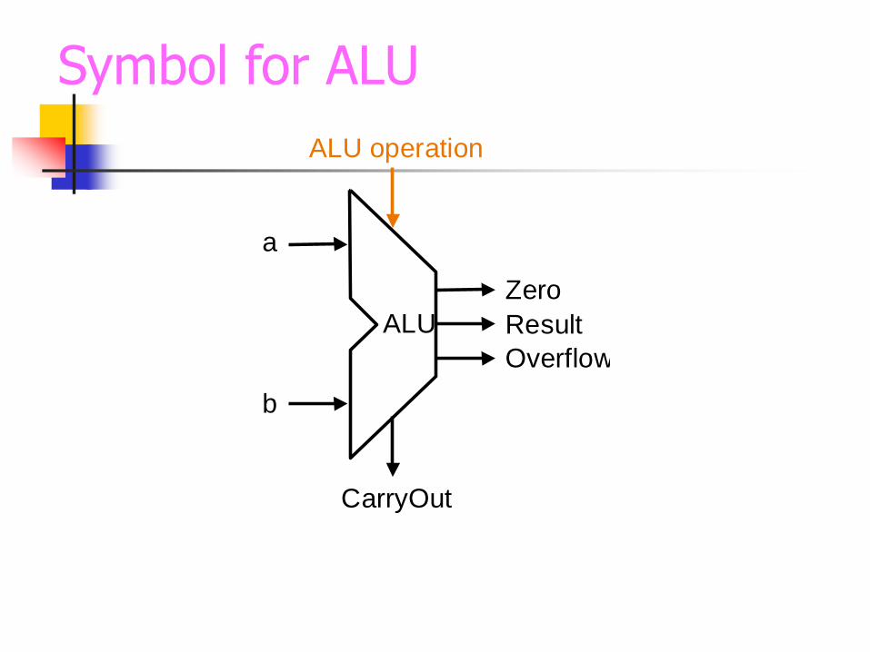
Symbol for ALU
ALU Result
Zero
Overflow
a
b
ALU operation
CarryOut

FP Arithmetic x / (Steps)
Check for zero, operands
Add/subtract exponents
Multiply/divide significands
watch sign
Normalize
Round
Double length intermediate results
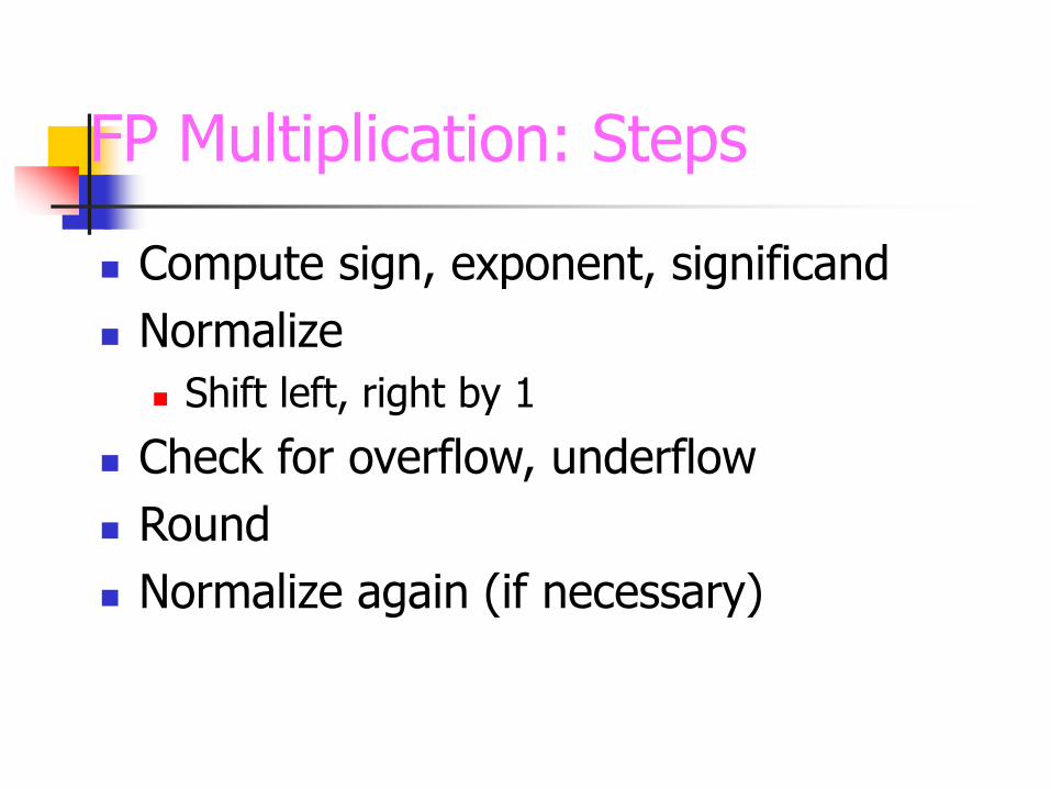
FP Multiplication: Steps
Compute sign, exponent, significand
Normalize
Shift left, right by 1
Check for overflow, underflow
Round
Normalize again (if necessary)
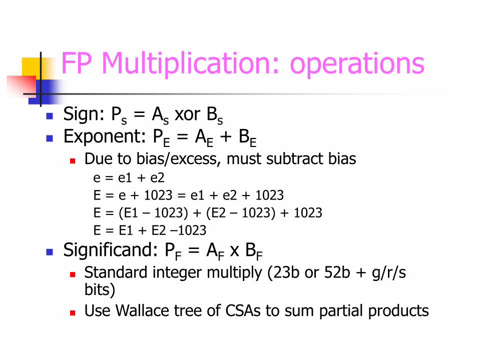
FP Multiplication: operations
Sign: Ps = As xor Bs
Exponent: PE = AE + BE
Due to bias/excess, must subtract bias e = e1 + e2
E = e + 1023 = e1 + e2 + 1023
E = (E1 – 1023) + (E2 – 1023) + 1023
E = E1 + E2 –1023
Significand: PF = AF x BF Standard integer multiply (23b or 52b + g/r/s
bits)
Use Wallace tree of CSAs to sum partial products

Efficient Multiplier Design
Radix-4 Booth Encoding Used to generate all partial products.
Sign Extension Prevention To prevent sign extension while doing signed number
addition (Padding of 1’s).
Optimized Wallace Addition Tree To sum up all operands to 2 vectors (sum, carry).
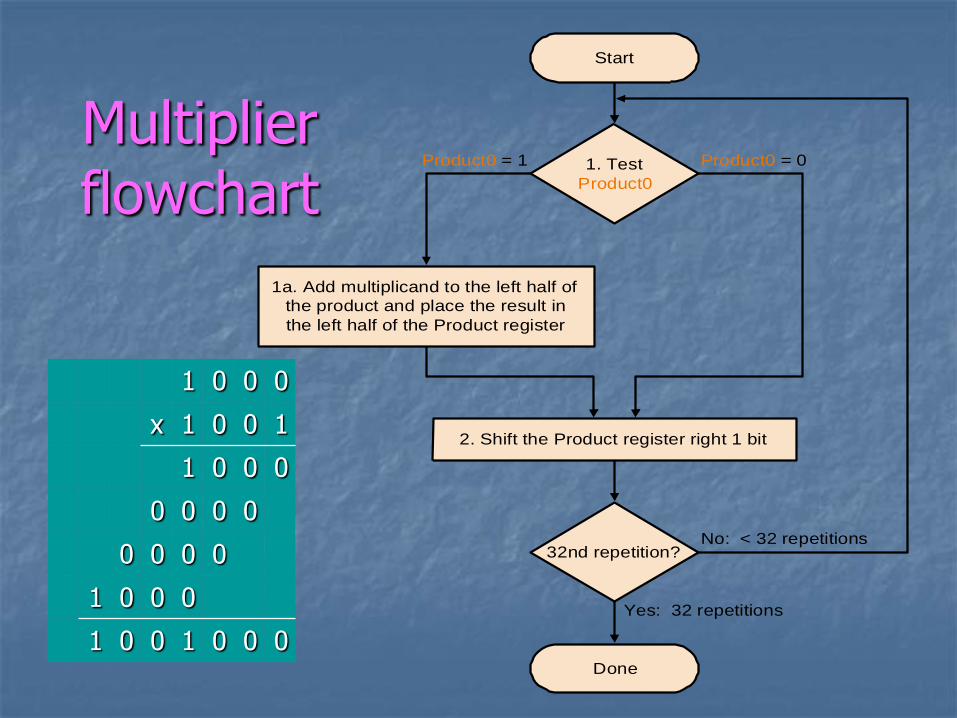
Multiplier flowchart
Done
1. Test
Product0
1a. Add multiplicand to the left half of
the product and place the result in
the left half of the Product register
2. Shift the Product register right 1 bit
32nd repetition?
Start
Product0 = 0Product0 = 1
No: < 32 repetitions
Yes: 32 repetitions
1 0 0 0
x 1 0 0 1
1 0 0 0
0 0 0 0
0 0 0 0
1 0 0 0
1 0 0 1 0 0 0

Step By Step Analysis

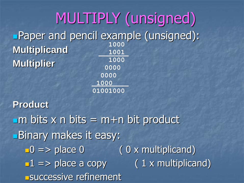
MULTIPLY (unsigned) Paper and pencil example (unsigned):
Multiplicand
Multiplier
Product
m bits x n bits = m+n bit product
Binary makes it easy:
0 => place 0 ( 0 x multiplicand)
1 => place a copy ( 1 x multiplicand)
successive refinement
1000
1001
1000
0000
0000
1000
01001000
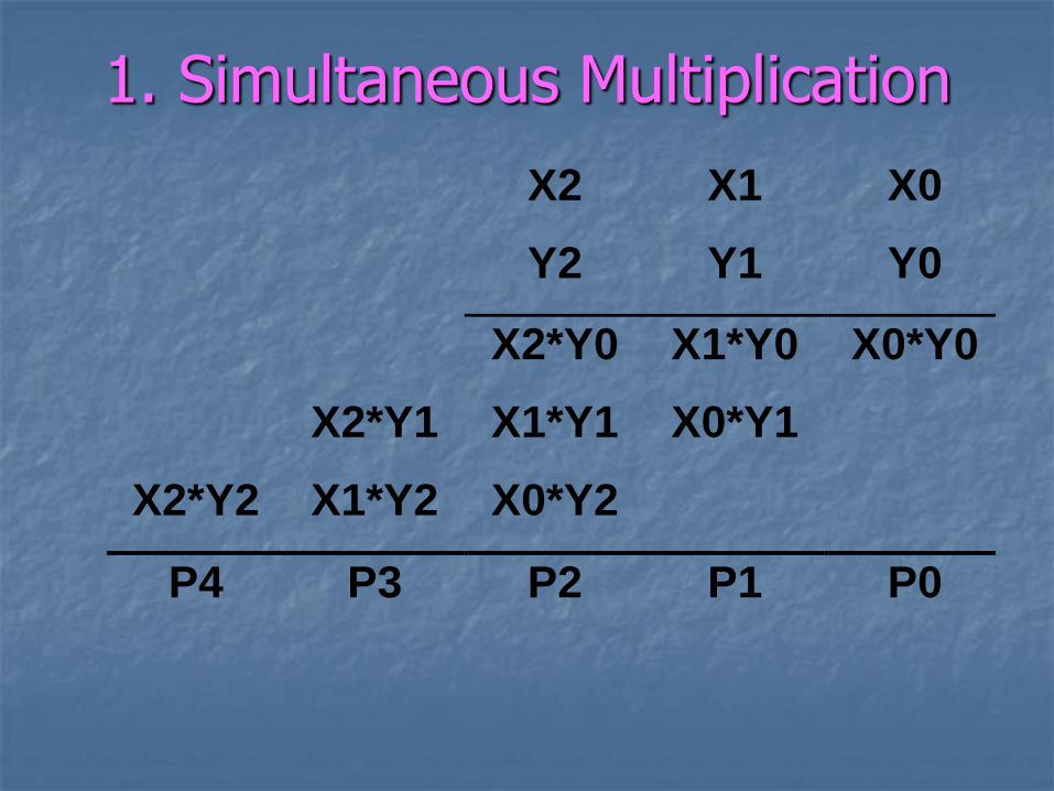
1. Simultaneous Multiplication
X2 X1 X0
Y2 Y1 Y0
X2*Y0 X1*Y0 X0*Y0
X2*Y1 X1*Y1 X0*Y1
X2*Y2 X1*Y2 X0*Y2
P4 P3 P2 P1 P0
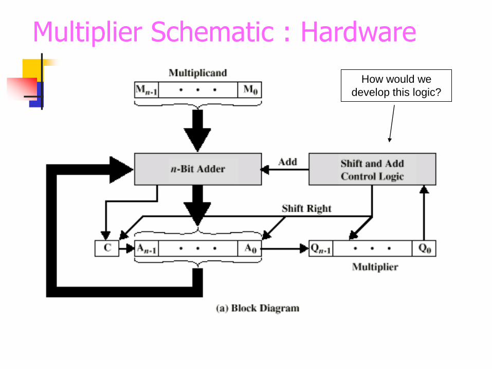
Multiplier Schematic : Hardware
How would we
develop this logic?

Multiplying Negative Numbers
This does not work when numbers are
negative, then for
Solution
Convert to positive if required
Multiply as above
If signs were different, negate answer
Use Booth‟s algorithm

Booth‟s Algorithm
Designed to improve speed by using fewer adds
Works best on strings of 1‟s
Example premise
7 = 8 – 1
0111 = 1000 – 0001 (3 adds vs 1 add – 1 sub)
Algorithm modified to allow for multiplication with negative numbers

Booth‟s Encoding
Really just a new way to encode numbers
Normally positionally weighted as 2n
With Booth, each position has a sign bit
Can be extended to multiple bits
0-> 1 1 0 Binary
+1 0 -1 0 1-bit Booth
+2 -2 2-bit Booth

Booth‟s Algorithm
Current bit
Bit to right
Explanation Example Operation
1 0 Begins run of „1‟ 00001111000 Subtract
1 1 Middle of run of „1‟ 00001111000 Nothing
0 1 End of a run of „1‟ 00001111000 Add
0 0 Middle of a run of „0‟ 00001111000 Nothing

S.
No Algorithms
Performance/Parameter
s
Serial
Multiplier
(Sequential)
Booth
Multiplier
Combination
al
Multiplier
Wallace
Tree
Multiplier
1. Optimum Area 110 LUTs 134 LUTs 4 LUTs 16 LUTs
2. Optimum Delay 9 ns 11 ns 9 ns 9 ns
3. Sequential Elements 105 DFFs 103 DFFs ---- ----
4. Input/Output Ports 67 / 71 50 / 49 4 / 4 24 / 18
5. CLB Slices(%) 57(7.42%) 71(36.98%) 2(1.04%) 8(4.17%)
6. Function Generators 114(7.42%) 141(36.72
%)
4(1.04%) 16(4.17%
)
7. Data Required Time/
Arrival Time
9.54 ns
8.66 ns
9.54 ns
9.36 ns
NA
8.61
10 ns
8.52 ns
8. Optimum Clock
(MHz)
100 101.9 NA 100
9. Slack 0.89 ns 0.19 ns Unconstraine
d path
1.48 ns
Comparison between various Architectures

Observations on Multiplication
Can speed up algorithm by doing 2 bits at a time, instead of just one
Using Booth encoding strategy (in more depth)
Multiplication algorithm Sequential version are more efficient than combinational in
terms of Hardware, Synchronization, speed
Can use carry save adders instead of ripple adder
A Wallace tree structure to combine the partial products is another excellent enhancement in Architecture

Suppose there are two numbers M, N. We have to find A=M*N,
lets assume the
M & N both are B base number And also M<N.
A = MN – (M*B - N*(M-1)) Next step: Subtract the M*B from MN,
Where MN can be found by just writing
both the numbers into a large register,
And M*B is also easy to generate.
It is just shifting towards left of operand with zero padding.
Again we will restore the number (M-1) in place of M by just
decrementing.
The continuous iteration will decrement the M and finally it will
reach to 1.
Multiplication Using Recursive Subtraction
Q and A