florida department of transportation design bulletin c11-08 implementation of new design standards,...
TRANSCRIPT

Florida Department of Transportation
RICK SCOTT GOVERNOR
605 Suwannee Street Tallahassee, FL 32399-0450
ANANTH PRASAD SECRETARY
www.dot.state.fl.us
STRUCTURES DESIGN BULLETIN C11-08
DATE: July 12, 2011
TO: District Directors of Operations, District Directors of Production, District
Design Engineers, District Construction Engineers, District Geotechnical Engineers, District Structures Design Engineers
FROM: Robert V. Robertson, P. E., State Structures Design Engineer COPIES: Ananth Prasad, Brian Blanchard, David Sadler, Charles Boyd, Rudy Powell,
Melissa Hollis, Jeffrey Ger (FHWA) SUBJECT: Implementation of new Design Standards, Design Guidelines and Construction
Specifications for Polymeric Bridge Fender Systems This bulletin implements new requirements for Bridge Fender Systems. REQUIREMENTS
1. Design Standards
Design Standards Indexes 21900, 21910, 21920 and 21930 have been removed and replaced in the July 2011 Interims with the drawings as shown in Attachment A as listed below. Attachment A: Index 21900 (7 sheets): Fender System – Polymeric Piles Index 21930 (7 sheets): Fender System – Prestressed Concrete Piles
2. Instructions for Design Standards (IDS)
IDS “Index 21900 Series Fender Systems” has been replaced as part of the July 2011 Interims with the two new IDS as shown in Attachment B as listed below. Attachment B: IDS, Index 21900 Fender Systems – Polymeric Piles IDS, Index 21930 Fender Systems – Prestressed Concrete Piles
ARCHIVED

Structures Design Bulletin C11-08 Implementation of new Design Standards, Design Guidelines and Construction Specifications for Polymeric Bridge Fender Systems Page 2 of 3
www.dot.state.fl.us
3. 2011 Structures Manual, Volume 1: Structures Design Guidelines (SDG)
Remove SDG, Section 3.14 and replace it with the new SDG, Section 3.14 as provided in Attachment C.
4. Standard Specifications for Road and Bridge Construction
Standard Specifications Sections 973 and 471 will be replaced in the January 2012 Workbook with the new sections as provided in Attachment D as listed below.
Attachment D: Standard Specifications Section 973 – Structural Plastics Standard Specifications Section 471 – Polymeric Fender Systems
5. Basis of Estimates (BOE) Manual
Section 455-37 of the BOE will be removed and replaced with a new Section 471-2 on January 1, 2012 as provided in Attachment E.
BACKGROUND Due to the introduction of new piling products which allows for increased competition, the Department has readdressed bridge fender system designs to include polymeric piling products which will be listed on the Qualified Products List (QPL). In general, polymeric materials are being developed for many different structural applications; however, there are currently no national standards in place for the manufacturing processes and materials associated with polymeric piling. Modifications to the Standard Specifications, Structures Design Guidelines and Design Standards are necessary in order to accommodate the use of polymeric piling products on FDOT bridge fender systems. COMMENTARY Changes to the Standard Specifications include the removal of the existing material specification for bridge fender system piling in Specification Section 973 and the addition of piling performance requirements to Specification Section 471. The Structures Design Guidelines (SDG), Section 3.14 has been rewritten to give thorough guidance to both the Engineer of Record and the Supplier’s Engineer. Fender systems are no longer classified as “Light Duty”, “Medium Duty” or “Heavy Duty”; therefore, Design Standards Indexes 21910 and 21920 are deleted. Designs will use the basic geometry of the fender system, standard connection details if possible, and limitations for pile spacing and pile clusters that are shown in revised Design Standards Index 21900. Each polymeric piling supplier will develop pile configurations and connection details for fender systems that result in flexible, energy absorbing structures maximizing the efficiency of their proprietary polymeric pile. These pile configurations will be listed on the QPL.
ARCHIVED

Structures Design Bulletin C11-08 Implementation of new Design Standards, Design Guidelines and Construction Specifications for Polymeric Bridge Fender Systems Page 3 of 3
www.dot.state.fl.us
For the time being, Design Standards Index 21930 which utilizes Prestressed Concrete Piles will continue to be available for limited use as before. IMPLEMENTATION This policy is effective for all projects let after January 1, 2012 containing bridge fender systems. Projects let prior to January 1, 2012 with current specifications and existing construction projects may incorporate the new requirements under the Cost Savings Initiative Proposal provisions of Supplemental Specifications Section 4-3.9. CONTACT Gevin McDaniel, P.E. Senior Structures Design Engineer Florida Department of Transportation 605 Suwannee Street, MS 33 Tallahassee, FL 32399-0450 Phone (850)-414-4284 [email protected] RVR/gjm Attachments
ARCHIVED

Attachment A:
Design Standards Index 21900: Fender System – Polymeric Piles
Design Standards Index 21930: Fender System – Prestressed Concrete Piles
ARCHIVED

REVISIONSDATE BY DESCRIPTION DATE BY DESCRIPTION
GENERAL NOTES
POLYMERIC PILES
FENDER SYSTEM -
1 of 7
InterimDate
07/01/11
21900
Sheet No.
Index No.
2010 Interim Design Standard
SPLICE PLATES: Furnish Splice Plates in accordance with ASTM A240 Type 316.
Threaded Bars and Nuts free from dirt, coarse grime and sand to prevent galling and seizing during tightening.
heads and nuts. Torque Nuts on 1" diameter Bolts and Threaded Bars to 150 lb-ft. Keep threads on Bolts,
ASTM F593 Type 305. Furnish stainless steel Washers compatible with Bolts, Threaded Rods and Nuts under
steel Nuts in accordance with ASTM F594 Type 316. Furnish stainless steel Screws in accordance with
Type 316. Furnish stainless steel Threaded Bars in accordance with ASTM A193 Grade B8M. Furnish stainless
BOLTS, THREADED BARS, NUTS, SCREWS AND WASHERS: Furnish stainless steel Bolts in accordance with ASTM F593
construction until permanent Navigation Lights are operational.
Index No. 21220 and/or project specific details. Provide and maintain Temporary Navigation Lights during
NAVIGATION LIGHTS: Provide and install Navigation Lights in accordance with Specification Section 510,
Clearance Gauge Light in accordance with Specification Section 510 and Index No. 21220.
distance shall be determined by the United States Coast Guard District Commander. Provide and install
Clearance Gauge width and numeral height is dependant on visibility distance. The required visibility
CLEARANCE GAUGE AND LIGHT: Clearance Gauge to be furnished by the FDOT and erected by the Contractor.
action.
2’-0" maximum spacing so as to resist pedestrian live loads and uplift forces from wind, buoyancy and wave
hardware, screws, bolts, nuts and washers. Attach Fiberglass Open Grating to Wales and Deck Supports at a
Install Fiberglass Open Grating according to manufacturer’s recommendations using stainless steel
of Fiberglass Open Grating shall be gray or black.
 concentrated load of 250 pounds with a maximum deflection of ˘�" at the center of a simple span. Co
 uniformly distributed load with a maximum deflection of ˘�" or L/120 at the center of a simple span a
gap opening on the walkway surface shall be 1b". Design live loads and deflections shall be a 50 psf
Plans. Fiberglass Open Grating shall be a heavy duty design suitable for exterior installations. Maximum
FIBERGLASS OPEN GRATING FOR CATWALKS: Provide Fiberglass Open Grating for catwalks when called for in the
(minimum) deck screws.
Install Plastic Lumber Decking according to manufacturer’s recommendations using stainless steel #10 x 3"
Plans in accordance with Specification Section 973.
PLASTIC LUMBER DECKING FOR CATWALKS: Provide Plastic Lumber decking for catwalks when called for in the
spliced only at locations shown on the plans.
Composite Lumber Wales in accordance with Specification Section 973. Wales shall be continuous and
PLASTIC LUMBER AND STRUCTURAL COMPOSITE LUMBER WALES: Provide only Plastic Lumber and Structural
be in accordance with manufacturer’s recommendations. All piles shall be plumb.
POLYMERIC PILES - Provide polymeric piles in accordance with Specification Section 471. Installation shall
beginning of construction of the Fender System.
U.S. COAST GUARD NOTIFICATION: Notify the local office of the U.S. Coast Guard at least 30 days prior to
GENERAL NOTES:
07/01/11 GJM
changes to specifications.
piling, wales, and dimensional lumber notes to reflect
Deleted "INSTRUCTION TO DESIGNERS" note; Changed title,
For Inf
ormati
on O
nly
ARCHIVED

For Navigation Light Details see Design Standards Index 21220.
of Variables in Structures Plans.
Dimension "L" and Clear Channel Width see Fender System Table
For Stations and Offsets of referenced Control Points A, B, C and D,
CROSS REFERENCES:
Skew Angle.
Layout Sheets for magnitude and orientation of Channel
* See Structures Plans, Plan and Elevation and Foundation
Navigation Light
Point D
Control
Begin Flare
2
Cle
ar Channel
Cle
ar Channel
Coping Line
90°
Min.
10’-0" Control Point B
Begin Flare
Dimension "L" (Multiples of 16’-0")
Angle
Skew
* Channel
Navigation Light
Line
Coping
Min.
10’-0"
Right Fender
& Navigation Light
Lighted Clearance Gauge
Control Point C
Begin Flare
90°
Control Point A
Begin Flare
Left Fender
Navigation Light & Navigation Light
Lighted Clearance Gauge
(Stationing Line)
� Survey or � Const
� Ch
of Stationin
g
Direction
Navigation Light
Point D
Control
Begin Flare
2
Cle
ar Channel
Cle
ar ChannelCoping Line
Control Point B
Begin Flare
Light
Navigation
90°
(Multiples of 16’-0")
Dimension "L"
of Statio
nin
g
Dir
ectio
n
Light
Gauge & Navigation
Lighted Clearance
Left Fender
Control Point A
Begin Flare
(Typ.)
10’-0" Min.
Navigation Light
Coping Line
Control Point C
Begin Flare
& Navigation Light
Lighted Clearance Gauge
Right Fender
� Ch
(Stationing Line)
� Survey or � Const
Navigation Light
Control Point D
Begin Flare
2
Cle
ar Channel
Cle
ar ChannelCoping Line
Control Point B
Begin Flare
& Navigation Light
Lighted Clearance Gauge
Light
Navigation
of Statio
nin
g
Dir
ectio
n
90°
(Multiples of 16’-0")
Dimension "L"
Right Fender
Control Point C
Begin Flare
Coping Line
& Navigation Light
Lighted Clearance Gauge
(Typ.)
10’-0" Min.
Control Point A
Begin Flare
Left Fender
Navigation Light
� B
� Ch
Navigation Light
Point D
Control
Begin Flare
2
Cle
ar Channel
Cle
ar Channel
Control Point B
Begin Flare
90°
Line
Coping
Min.
10’-0
"
of Statio
nin
g
Directio
n
Dimension "L" (Multiples of 16’-0")
Angle
* Channel Skew
Light
Navigation Coping Line
Min.
10’-0
"
90°
Control Point C
Begin Flare
Right Fender
& Navigation Light
Lighted Clearance Gauge
Control Point A
Begin Flare
Left Fender
Navigation Light& Navigation Light
Lighted Clearance Gauge � B
� Ch
LAYOUT GEOMETRY
POLYMERIC PILES
FENDER SYSTEM -
2 of 7
InterimDate
07/01/11
21900
Sheet No.
Index No.
2010 Interim Design Standard
SINGLE FIXED BRIDGE WITH NONSKEWED CHANNEL
SCHEMATIC OF FENDER SYSTEM SHOWING TREATMENT OF
(PARALLEL DUAL FIXED BRIDGES SHOWN, NONPARALLEL DUAL FIXED BRIDGES SIMILAR)
SCHEMATIC OF FENDER SYSTEM SHOWING TREATMENT OF DUAL FIXED BRIDGES WITH NONSKEWED CHANNEL
(PARALLEL DUAL FIXED BRIDGES SHOWN, NONPARALLEL DUAL FIXED BRIDGES SIMILAR)
SCHEMATIC OF FENDER SYSTEM SHOWING TREATMENT OF DUAL FIXED BRIDGES WITH SKEWED CHANNEL
SINGLE FIXED BRIDGE WITH SKEWED CHANNEL
SCHEMATIC OF FENDER SYSTEM SHOWING TREATMENT OF
REVISIONSDATE BY DESCRIPTION DATE BY DESCRIPTION
07/01/11 GJM
bridges only; Changed title.
Added clarification that this layout geometry is for fixed
For Inf
ormati
on O
nly
ARCHIVED
~
MINIMUM
0 0
0 0
0 0
0 0
0 0
0 0
0 0 Gauge
Clearance
Lighted
Locations & Details)
Standards Index 21220 for
Navigation Light (See Design
Wales Mark A6
Composite Lumber 10" x 10"
Mark F6
Plastic Lumber 6" x 10"
Grating similar (Typ.)
Mark E shown, Fiberglass Open
Plastic Lumber 2" x 12" Decking
Mark F5
Plastic Lumber 6" x 10"
Wales Mark A5
Composite Lumber 10" x 10"
Wales Mark A5
Composite Lumber 10" x 10"
Mark F5
Plastic Lumber 6" x 10"
Wales Mark A4
Composite Lumber 10" x 10"
Mark F4
Plastic Lumber 6" x 10"
Mark B (Typ.)
Spacer Blocks
Plastic Lumber 8" x 8"Wales Mark A3
Composite Lumber 10" x 10"
Plastic Lumber 6" x 10" Mark F2 or F3
Composite Lumber 10" x 10" Wales Mark A2
Wales Mark A1, A2 or A3
Composite Lumber 10" x 10"
Wales Mark A1, A2 or A3
Composite Lumber 10" x 10"
Mark F1, F2 or F3
Plastic Lumber 6" x 10"
Mark F (Back Face, Top)
Plastic Lumber 6" x 10"
Fender) (Typ.)
Mark A (along Front Face of
Composite Lumber 10" x 10" Wales
16’-0"16’-0" (Typ. Straight Panel)
Wales Mark A (Typ.)
Composite Lumber 10" x 10"
Cle
ar Channel
Front Face of Fender
Begin Flare
Control Point B
16’-0"
4°
16’-0"
8° 16
’-0"
8°
16’-0
"
8°
–
Navigation Light
Gauge
Lighted Clearance
1’-8"
1’-8"
Fender
Back Face of 1’-8"
Mark F (Typ.)
6" x 10" Deck Support
Plastic Lumber
1’-8"
Post Mark D (Typ.)
Plastic Lumber 4" x 6"
1’-8"
(Typ. for Straight Sections)
(Typ. for Straight Sections)
1’-8"
Grating similar (Typ.)
Mark E shown, Fiberglass Open
Plastic Lumber 2" x 12" Decking
�
" –b15’-11 " –�15’-7 " –�15’-0 " –b14’-1
" –
�1’-
1"
�3’-
3"
–�
5’-
5"
–�
7’-
6
BA
A B
F F
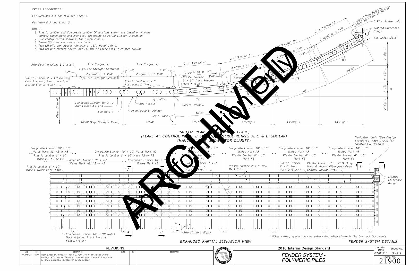
EXPANDED PARTIAL ELEVATION VIEW
(HANDRAIL NOT SHOWN FOR CLARITY)
(FLARE AT CONTROL POINT B SHOWN, CONTROL POINTS A, C & D SIMILAR)
PARTIAL PLAN VIEW (TYPICAL FLARE)
Pile Clusters (Typ.)
Pile Spacing (along � Clu 2 or 3 equal sp. 2 or 3 equal sp. 2 or 3 equal sp.
2 or 3 e
qual sp.
2 or 3 eq
ual s
p.
2 or 3 e
qual s
p.
POLYMERIC PILES
FENDER SYSTEM -
3 of 7
InterimDate
07/01/11
21900
Sheet No.
Index No.
2010 Interim Design Standard
2 eq
ual sp. – 1’-0
"
2 equ
al sp. – 1’-0"
2 equal
sp. – 1’
-0"
2 equal sp. – 1’-0" 2 equal sp. – 1’-0"2 equal sp
. – 1’-0"
See Note 4
See Note 5
3 Pile cluster only
(along bac
k fa
ce of
Fend
er)
Handr
ail Po
st S
pacing
FENDER SYSTEM DETAILS
Mark D (Typ.) *
4" x 6" Post
Plastic Lumber
Mark C *
Plastic Lumber 2" x 6" Rail
* Other railing system may be substituted when shown in the Contract Documents.
5. Two (2) pile cluster shown, one (1) pile or three (3) pile cluster similar.
4. Two (2) pile per cluster minimum at 16ft. Panel Joints.
3. Three (3) piles per cluster maximum.
2. Pile configuration shown is for example only.
Lumber Dimensions and may vary depending on Actual Lumber Dimension.
1. Plastic Lumber and Composite Lumber Dimensions shown are based on Nominal
NOTES:
For View F-F see Sheet 5.
For Sections A-A and B-B see Sheet 4.
CROSS REFERENCES:
REVISIONSDATE BY DESCRIPTION DATE BY DESCRIPTION
07/01/11 GJM
to show allowable number of equal spaces.
configuration notes. Removed specific pile spacing dimensions
New Sheet (Previously Index 21910, Sheet 1); Added piling
For Inf
ormati
on O
nly
ARCHIVED

~ ~
Spacer Block Mark B (Typ.)
Plastic Lumber 8" x 8"
Conduit
SCH 80 PVC Electrical
Post Mark D (Typ.)
Plastic Lumber 4" x 6"
(Typ.)
Support Mark F
6" x 10" Deck
Plastic Lumber
Detail "A"
See
1’-
9" (T
yp.)
Mark A
10" x 10" Wales
Composite Lumber
Nuts and Washers (Typ.)
Threaded Bars, Locking
1" Ø Stainless Steel
Nuts and Washers (Typ.)
Threaded Bars, Locking
" Ø Stainless Steel b2 ~
Spacer Block)
Screw (Recess head flush with
" Ø x 12" Stainless Steel Lag �
(
� Spacer
B
SCH 80 PVC Electrical Conduit
Support Mark F
6" x 10" Deck
Plastic Lumber
See Detail "A"
Mark B (Typ.)
Spacer Blocks
Plastic Lumber 8" x 8"
Mark A
10" x 10" Wales
Composite Lumber
Nuts and Washers (Typ.)
Threaded Bars, Locking
1" Ø Stainless Steel
Spacer Block)
head flush with top of
Steel Lag Screw (Recess
" Ø x 12" Stainless �
Elevation
NLW or MLW
Wales Mark A (Typ.)
Composite Lumber 10" x 10"
Mark B (Typ.)
Spacer Blocks
Plastic Lumber 8" x 8"
Elevation
NHW or MHW
minus 1’-0"
Elevation
Pile Cutoff
1’-
2"
except along top Wale)
each Wale splice location
bottom of Wale (Typ. at
Splice Plate top and
8’-
0"
Min.
2"
5"
1’-
4"
1’-
0"
Support Mark F
6" x 10" Deck
Plastic Lumber
1"1’-
9"
3’-
6"
Elevation
Pile Cutoff
similar
Fiberglass Open Grating
Decking Mark E shown,
Plastic Lumber 2" x 12"
2" x 6" Rail Mark C
Plastic Lumber Post Face
2"
of Fender
Front Face @ 2’-0" Ctrs.
Steel Decking Screws
#10 x 3" Stainless
6" x 10" Mark F
Plastic Lumber
Post Mark D
Plastic Lumber 4" x 6"
5"
SCH 80 PVC Electrical Conduit
(Center in Post)
Steel Decking Screws
2 ~ #10 x 3" Stainless
1’-
9" (T
yp.) Detail "A"
See
Support Mark F
6" x 10" Deck
Plastic Lumber
Mark A
10" x 10" Wales
Composite Lumber
Spacer Block Mark B (Typ.)
Plastic Lumber 8" x 8"Post Mark D (Typ.)
Plastic Lumber 4" x 6"
Conduit
SCH 80 PVC Electrical
(Typ.)
1’-
0"
Piles (Typ.)
16" Ø Composite
with Spacer Blocks)
(Recess head flush
Steel Lag Screws
˘�" ˆ� x 12" Stain
Nuts and Washers (Typ.)
Threaded Bars, Locking
1" Ø Stainless Steel
"b
1’-
7
Deck Support)
Post to 6" x 10"
Nuts and Washers (4" x 6"
Threaded Bars, Locking
" Ø Stainless Steel b�»
Post to 6" x 10" Deck Support)
Locking Nuts and Washers (4" x 6"
" Ø Stainless Steel Threaded Bars, b�»
"b
1’-
7
at each Post, centered, Typ.)
Washers (1 per each Rail
Bolts, Locking Nuts and
" Ø Stainless Steel � Spacer Block)
head flush with top of
Steel Lag Screw (Recess
" Ø x 12" Stainless �
(
� Spacer
B
"(8°)
�9
Nuts and Washers (Typ.)
Threaded Bars, Locking
1" Ø Stainless Steel
Nuts and Washers (Typ.)
Threaded Bars, Locking
" Ø Stainless Steel b2 ~
DDCC
E E
TYPICAL STRAIGHT SECTION
SECTION C-C
TYPICAL AT INTERMEDIATE PILES
SECTION D-D
SECTION A-A
SECTION B-B (8° TURN SHOWN, 4° TURN SIMILAR)
TYPICAL FLARED SECTION
SECTION C-C
HANDRAIL DETAIL
accept nut & washer
Provide oversized hole to
DETAIL "A"
face of Wale as shown
Bar b" from front
Recess Threaded
2’-4" (min.)
For Section E-E see Sheet 5.
B-B see Sheet 3.
For locations of Sections A-A and
CROSS REFERENCES:
Cluster similar
shown, 2-Pile
3-Pile Cluster
Cluster similar
shown, 2-Pile
3-Pile Cluster
1-Pile similar
2-Pile Cluster shown,
Electrical Conduit
SCH 80 PVC
required.
minimum of two (2) bolts is
height at 1’-2" spacing. A
may increase along the pile
Number of bolts per design
bPile Ø
(6"
min.)
(6"
min.)
bPile Ø
(6"
min.)
bPile Ø
bPile Ø
(6"
min.)
(6"
min.)
(6"
min.)
b Pile Ø
b Pile Ø
POLYMERIC PILES
FENDER SYSTEM -
4 of 7
InterimDate
07/01/11
21900
Sheet No.
Index No.
2010 Interim Design Standard
FENDER SYSTEM DETAILS
documents
shown in the Contract
or other railing system
Plastic Lumber railing
"2
13
"213 "2
13
"213
3"
3"
REVISIONSDATE BY DESCRIPTION DATE BY DESCRIPTION
07/01/11 GJM
connection of Mark D to Mark F.
for various pile types and sizes; Changed bolt configuration for
New Sheet (Previously Index 21910, Sheet 2); Modified to allow
For Inf
ormati
on O
nly
ARCHIVED

~
~
Spacer Blocks Mark B (Typ.)
Plastic Lumber 8" x 8"Wales Mark A (Typ.)
Composite Lumber 10" x 10"
1’-
9" (T
yp.)
Detail "A"
See
except along top Wale)
(Typ. at each Wale splice location,
center plate about splice and �
Splice Plate top and bottom of Wale,
Nuts and Washers (Typ.)
Threaded Bars, Locking
1" Ø Stainless Steel
Nuts and Washers (Typ.)
Threaded Bars, Locking
1" Ø Stainless Steel
top of Spacer Block)
Screw (Recess head flush with
" Ø x 12" Stainless Steel Lag �
(
� Spacer
B
11"
2’-9"
8"11"
" Ø Holes (Typ.)�1 " Stainless Steel Plate�
"b1"b1
"b
3
6" x 10" Mark F
Plastic Lumber
2" Offset for Decking
of each Mark E
Decking Screws each end
3 ~ #10 x 3" Stainless Steel,
10" x 10" Wales Mark A
Composite Lumber
Spacer Block Mark B
Plastic Lumber 8" x 8"
62° –
90°
Light
for Navigation
Orientation line
Support Mark F
6" x 10" Deck
Plastic Lumber
Navigation Light
Plastic Lumber 4" x 6" Post Mark D
& Light
Clearance Gauge
Support Mark H
Clearance Gauge
Plastic Lumber 2" x 6"
Electrical Conduit
SCH 80 PVC
Bracing Mark G
Plastic Lumber 8" x 8"
4" x 6" Post Mark D
Plastic Lumber
Hand Rail Mark C
Plastic Lumber 2" x 6"
between adjacent boards
" Max. gap b" Min., �at turns, placed with
Fiberglass Open Grating similar (6" Min. width
Plastic Lumber 2" x 12" Decking Mark E shown,

� Ch
SCH 80 PVC Electrical Conduit
Mark A
10" x 10" Wales
Composite Lumber
See Detail "A"
(Typ.)
Spacer Blocks Mark B
Plastic Lumber 8" x 8"
(Typ.)
Nuts and Washers (Typ.)
Threaded Bars, Locking
" Ø Stainless Steel b2 ~
Nuts and Washers (Typ.)
Threaded Bars, Locking
1" Ø Stainless Steel
top of Spacer Block)
Screw (Recess head flush with
" Ø x 12" Stainless Steel Lag �
Spacer Blocks Mark B (Typ.)
Plastic Lumber 8" x 8"
10" x 10" Wales Mark A
Composite Lumber
Detail "A"
See
1’-
9" (T
yp.)
except along top Wale)
(Typ. at each Wale splice location,
center plate about splice and �
Splice Plate top and bottom of Wale,
Nuts and Washers (Typ.)
Threaded Bars, Locking
1" Ø Stainless Steel
Nuts and Washers (Typ.)
Threaded Bars, Locking
1" Ø Stainless Steel
top of Spacer Block)
Screw (Recess head flush with
" Ø x 12" Stainless Steel Lag �
(
� Spacer
B
" –
b1’-
4"
–b
1’-
4
FENDER END WITHOUT CLEARANCE GAUGE SIMILAR)
(SHOWING FENDER END WITH CLEARANCE GAUGE;
VIEW F-F
NOT SHOWN FOR CLARITY)
HANDRAIL AND CLEARANCE GAUGE
(SHOWING FENDER END; DECKING,
VIEW F-F
(8° TURN SHOWN, 4° TURN SIMILAR)
TYPICAL FLARED SECTION
SECTION E-E
TYPICAL STRAIGHT SECTION
SECTION E-E
SPLICE PLATE DETAIL
Cluster
3-Pile
Cluster Similar
shown, 2-Pile
3-Pile Cluster
Cluster similar
shown, 2-Pile
3-Pile Cluster
H H
SCH 80 PVC Electrical Conduit
1’-
2"
1’-
4"
1’-
0"
2"
Navigation Light
"b
1’-
7
Nuts and Washers (Typ.)
Threaded Bar, Locking
1" Ø Stainless Steel
(CLEARANCE GAUGE NOT SHOWN FOR CLARITY)
SECTION H-H
3-Pile Cluster
G
G
Polymeric Piles (Typ.)
For location of Section E-E see Sheet 4.
For location of View F-F see Sheet 3.
Sheet 6.
For Clearance Gauge Details and View G-G see
Conduit Details see Design Standard Index 21220.
For Navigation Lights and SCH 80 PVC Electrical
CROSS REFERENCES:
POLYMERIC PILES
FENDER SYSTEM -
5 of 7
InterimDate
07/01/11
21900
Sheet No.
Index No.
2010 Interim Design Standard
b Pile Ø
(6"
min.)
(6"
min.)
b Pile Ø
(6"
min.)
b Pile Ø
b Pile Ø
(6"
min.)
(6"
min.)
b Pile Ø
b Pile Ø
(6"
min.)
FENDER SYSTEM DETAILS
other systems similar
railing shown,
Plastic Lumber
"2
13
"2
13
Nuts and Washers (Typ.)
Threaded Bars, Locking
" Ø Stainless Steel b2 ~ 

8"
3"
ï »¿̆�" (M
˘�" (M
REVISIONSDATE BY DESCRIPTION DATE BY DESCRIPTION
07/01/11 GJM
splice plate.
for connection of Mark D to Mark F. Modified dimensions of
for various pile types and sizes; Changed bolt configurations
New Sheet (Previously Index 21910, Sheet 3); Modified to allow
For Inf
ormati
on O
nly
ARCHIVED

~
~
Wales Mark A6
Composite Lumber 10" x 10"
Mark H1 (each face)
Clearance Gauge Support
Plastic Lumber 2" x 6"
Clearance Gauge
Bracing Mark G
Plastic Lumber 8" x 8"
Spacer Blocks Mark B (Typ.)
Plastic Lumber 8" x 8"
90° –
Clearance Gauge
Orientation line for
Front Face of Fender
ï »¿â �� Ch
Steel Lag Screws
" Ø x 1’-0" Stainless b
Locking Nuts & Washers
" Ø Stainless Steel Bolts, b
3’-
0"
Max.
(Typ.)
8"
8"
(Typ.)5"1’-0"
Equal spaces
@ 3’-
0"
Centers
Max.
Cle
arance
Gauge Bracin
g
Mark G2 (Typ.)
Mark G1 (Typ.)
2’-
0"
Elevation
Pile Cutoff
Light Support Mark H2
Plastic Lumber 2" x 6"
Clearance Gauge Light
Mark H1 (each face)
Clearance Gauge Support
Plastic Lumber 2" x 6"
Minimum Clearance Sign
3"
Clearance Gauge
Elevation
NLW or MLW
1’-
0"
5"
––
5"
3"
Width Varies
Clearance Gauge
Cle
arance
Gauge
Heig
ht
Varie
s
3’-
0"
C.C.
Max.
Spacin
g
3"
3"
3"Elevation
Cutoff
Match Pile 2’-
0"
3"
2’-
3"
8"
3"
Light Support Mark H2
Plastic Lumber 2" x 6"3’-6"
CLEARANCEMINIMUM
(Typ.)
Locking Nuts & Washers
" Ø Stainless Steel Bolts �
Washers (Typ.)
Bolt, Locking Nuts &
" Ø Stainless Steel b
Steel Lag Screws (Typ.)
" Stainless b" Ø x 1�
2" x 6" Mark H1
� Plastic Lu
& Bolts (Typ.)
Steel Lag Screws
" Ø x 1’-0" Stainless b&
8" x 8" Bracing Mark G
� Plastic Lu
Locking Nuts & Washers
" Ø Stainless Steel Bolts, �
NOT SHOW FOR CLARITY)
(WALES, PILES AND BRACING
VIEW J-J
CLEARANCE GAUGE DETAILS
NOT SHOWN FOR CLARITY)
(WALES, DECKING AND HANDRAIL
VIEW G-G
SECTION K-K
J
K K
J
3-Pile Cluster
For location of View G-G see Sheet 5.
of Variables see Structures Plans.
of Materials Quantities and Fender System Table
For Structural Composite and Plastic Lumber Bill
CROSS REFERENCES:
POLYMERIC PILES
FENDER SYSTEM -
6 of 7
InterimDate
07/01/11
21900
Sheet No.
Index No.
2010 Interim Design Standard
FENDER SYSTEM DETAILS
REVISIONSDATE BY DESCRIPTION DATE BY DESCRIPTION
07/01/11 GJM
for various pile types and sizes.
New Sheet (Previously Index 21910, Sheet 4); Modified to allow
For Inf
ormati
on O
nly
ARCHIVED

Bill
of
Materials Table in Structures Pla
ns
See Estim
ated Structural
Co
mposite and Pla
stic Lu
mber
1.0
LF EACH
1.0 PER
10.7
12.0
79.2
78.4
78.8
79.6
159.6
160.0
5.0
8.7
16.0
3.6
PER EACH
BOARD FT.
REQD.
NO.QUANTITYDIMENSIONS
8" (STRAIGHT)
as required)
(Trim & Miter Ends
16’-0" (STRAIGHT)
4’-4" (STRAIGHT)
(Miter as required)
2’-6" (STRAIGHT)
32’-0" (STRAIGHT)
6"
31’-11"
6"
15’-11"
6"
6"
6"
2’-3" (STRAIGHT)
2’-0" (STRAIGHT)
MLW ELEV. PLUS 5’-6" (STRAIGHT)
PILE CUTOFF ELEV. MINUS NLW OR
1’-0" (STRAIGHT)PLASTIC LUMBER
2" X 6"
PLASTIC LUMBER
2" X 6"
PLASTIC LUMBER
8" X 8"
H2
H1
G2
PLASTIC LUMBER
8" X 8"G1
F6
LUMBER
PLASTIC
6" X 10"
LUMBER
PLASTIC
6" X 10"
F5
F4
LUMBER
PLASTIC
6" X 10"
LUMBER
PLASTIC
6" X 10"
F3
F2
LUMBER
PLASTIC
6" X 10"
PLASTIC LUMBER
6" X 10"F1
** EPLASTIC LUMBER
2" X 12"
PLASTIC LUMBER
4" X 6"D
CPLASTIC LUMBER
2" X 6"
PLASTIC LUMBER
8" X 8"B
MARK(NOMINAL)
SIZE
"�
"�
"� "�
"�
"�15’-9
"�
"�15’-8
"�
"�15’-10
Bill
of
Materials Table in Structures Pla
ns
See Estim
ated Structural
Co
mposite and Pla
stic Lu
mber
QUANTITYREQD.
NO.
PER EACH
BOARD FT.
266.6
266.6
133.3
133.3
133.3
133.3
16’-0"
10"
16’-0"
10"
16’-0"10"
16’-0"
10"
32’-0"
10"
32’-0" (STRAIGHT)
DIMENSIONS(NOMINAL)
SIZEMARK
A1
LUMBER
COMPOSITE
10" X 10"
LUMBER
COMPOSITE
10" X 10"
A2
A3
LUMBER
COMPOSITE
10" X 10"
LUMBER
COMPOSITE
10" X 10"
A4
LUMBER
COMPOSITE
10" X 10"
A5
A6
LUMBER
COMPOSITE
10" X 10"
"�
"�"�
"�"�
"�
"�
PLASTIC LUMBER BILL OF MATERIALS*
STRUCTURAL COMPOSITE LUMBER BILL OF MATERIALS*
Notes and Details.
hardware shall be Stainless Steel, install per Manufacturer’s recommendations. See Structures Plans for
** Provide Fiberglass Open Grating in lieu of 2" X 12" Plastic Lumber when called for in the Plans. Mounting
Lumber Dimensions and may vary depending on Actual Lumber Dimension.
* All Plastic Lumber and Composite Lumber Dimensions and Quantities shown are based on Nominal
POLYMERIC PILES
FENDER SYSTEM -
7 of 7
InterimDate
07/01/11
21900
Sheet No.
Index No.
2010 Interim Design StandardREVISIONSDATE BY DESCRIPTION DATE BY DESCRIPTION
07/01/11 GJM
reference to "Index 21900".
New Sheet (Previously Index 21910, Sheet 5); Removed
For Inf
ormati
on O
nly
ARCHIVED

GENERAL NOTES
PRESTRESSED CONCRETE PILES
FENDER SYSTEM -
1 of 7
InterimDate
07/01/11
21930
Sheet No.
Index No.
2010 Interim Design Standard
Energy Capacity = 38 ft-k
FENDER SYSTEM ENERGY CAPACITY:
REVISIONSDATE BY DESCRIPTION DATE BY DESCRIPTION
07/01/11 GJM
polymeric piling fenders.
New Sheet; Added General Notes to separate this Index from
compatible with the rope�s polypropylene that provide an effective water-tight seal.
diameter of 5/8� with a minimum breaking strength of 22,000 lbs. Protect all ends with heat shrinkable end caps
2. ‰� diameter 6x19 galvanized wire rope with ultraviolet ray resistant polypropylene impregnation having an outside
of 18,000 lbs.
1. ‰� diameter 6x19, 6x25 or 6x37 class IWRC Type 316 stainless steel wire rope with a minimum breaking strength
WIRE ROPE: Provide wire rope meeting one of the following requirements:
SPLICE PLATES: Furnish Splice Plates in accordance with ASTM A240 Type 316.
Threaded Bars and Nuts free from dirt, coarse grime and sand to prevent galling and seizing during tightening.
heads and nuts. Torque Nuts on 1" diameter Bolts and Threaded Bars to 150 lb-ft. Keep threads on Bolts,
ASTM F593 Type 305. Furnish stainless steel Washers compatible with Bolts, Threaded Rods and Nuts under
steel Nuts in accordance with ASTM F594 Type 316. Furnish stainless steel Screws in accordance with
Type 316. Furnish stainless steel Threaded Bars in accordance with ASTM A193 Grade B8M. Furnish stainless
BOLTS, THREADED BARS, NUTS, SCREWS AND WASHERS: Furnish stainless steel Bolts in accordance with ASTM F593
construction until permanent Navigation Lights are operational.
Index No. 21220 and/or project specific details. Provide and maintain Temporary Navigation Lights during
NAVIGATION LIGHTS: Provide and install Navigation Lights in accordance with Specification Section 510,
Clearance Gauge Light in accordance with Specification Section 510 and Index No. 21220.
distance shall be determined by the United States Coast Guard District Commander. Provide and install
Clearance Gauge width and numeral height is dependant on visibility distance. The required visibility
CLEARANCE GAUGE AND LIGHT: Clearance Gauge to be furnished by the FDOT and erected by the Contractor.
action.
2’-0" maximum spacing so as to resist pedestrian live loads and uplift forces from wind, buoyancy and wave
hardware, screws, bolts, nuts and washers. Attach Fiberglass Open Grating to Wales and Deck Supports at a
Install Fiberglass Open Grating according to manufacturer’s recommendations using stainless steel
of Fiberglass Open Grating shall be gray or black.
 concentrated load of 250 pounds with a maximum deflection of ˘�" at the center of a simple span. Co
 uniformly distributed load with a maximum deflection of ˘�" or L/120 at the center of a simple span a
gap opening on the walkway surface shall be 1b". Design live loads and deflections shall be a 50 psf
Plans. Fiberglass Open Grating shall be a heavy duty design suitable for exterior installations. Maximum
FIBERGLASS OPEN GRATING FOR CATWALKS: Provide Fiberglass Open Grating for catwalks when called for in the
(minimum) deck screws.
Install Plastic Lumber Decking according to manufacturer’s recommendations using stainless steel #10 x 3"
Plans in accordance with Specification Section 973.
PLASTIC LUMBER DECKING FOR CATWALKS: Provide Plastic Lumber decking for catwalks when called for in the
spliced only at locations shown on the plans.
Composite Lumber Wales in accordance with Specification Section 973. Wales shall be continuous and
PLASTIC LUMBER AND STRUCTURAL COMPOSITE LUMBER WALES: Provide only Plastic Lumber and Structural
Concrete Piles with 8 - b" diameter Low Relaxation Strands fabricated in accordance with Index No. 20614.
equal to 6 (N = 6). Pile splices and build-ups are not permitted. Use only 14" Square Prestressed
sufficient length to achieve a minimum embedment of 20’ into soil having a blow count greater than or
14" SQUARE PRESTRESSED CONCRETE PILES - Provide 14" Square Prestressed Concrete Piles of
beginning of construction of the Fender System.
U.S. COAST GUARD NOTIFICATION: Notify the local office of the U.S. Coast Guard at least 30 days prior to
GENERAL NOTES:
For Inf
ormati
on O
nly
ARCHIVED

For Navigation Light Details see Design Standards Index 21220.
of Variables in Structures Plans.
Dimension "L" and Clear Channel Width see Fender System Table
For Stations and Offsets of referenced Control Points A, B, C and D,
CROSS REFERENCES:
Skew Angle.
Layout Sheets for magnitude and orientation of Channel
* See Structures Plans, Plan and Elevation and Foundation
Navigation Light
Point D
Control
Begin Flare
2
Cle
ar Channel
Cle
ar Channel
Coping Line
90°
Min.
10’-0" Control Point B
Begin Flare
Dimension "L" (Multiples of 16’-0")
Angle
Skew
* Channel
Navigation Light
Line
Coping
Min.
10’-0"
Right Fender
& Navigation Light
Lighted Clearance Gauge
Control Point C
Begin Flare
90°
Control Point A
Begin Flare
Left Fender
Navigation Light & Navigation Light
Lighted Clearance Gauge
(Stationing Line)
� Survey or � Const
� Ch
of Stationin
g
Direction
Navigation Light
Point D
Control
Begin Flare
2
Cle
ar Channel
Cle
ar ChannelCoping Line
Control Point B
Begin Flare
Light
Navigation
90°
(Multiples of 16’-0")
Dimension "L"
of Statio
nin
g
Dir
ectio
n
Light
Gauge & Navigation
Lighted Clearance
Left Fender
Control Point A
Begin Flare
(Typ.)
10’-0" Min.
Navigation Light
Coping Line
Control Point C
Begin Flare
& Navigation Light
Lighted Clearance Gauge
Right Fender
� Ch
(Stationing Line)
� Survey or � Const
Navigation Light
Control Point D
Begin Flare
2
Cle
ar Channel
Cle
ar ChannelCoping Line
Control Point B
Begin Flare
& Navigation Light
Lighted Clearance Gauge
Light
Navigation
of Statio
nin
g
Dir
ectio
n
90°
(Multiples of 16’-0")
Dimension "L"
Right Fender
Control Point C
Begin Flare
Coping Line
& Navigation Light
Lighted Clearance Gauge
(Typ.)
10’-0" Min.
Control Point A
Begin Flare
Left Fender
Navigation Light
� B
� Ch
Navigation Light
Point D
Control
Begin Flare
2
Cle
ar Channel
Cle
ar Channel
Control Point B
Begin Flare
90°
Line
Coping
Min.
10’-0
"
of Statio
nin
g
Directio
n
Dimension "L" (Multiples of 16’-0")
Angle
* Channel Skew
Light
Navigation Coping Line
Min.
10’-0
"
90°
Control Point C
Begin Flare
Right Fender
& Navigation Light
Lighted Clearance Gauge
Control Point A
Begin Flare
Left Fender
Navigation Light& Navigation Light
Lighted Clearance Gauge � B
� Ch
LAYOUT GEOMETRY
PRESTRESSED CONCRETE PILES
FENDER SYSTEM -
2 of 7
InterimDate
07/01/11
21930
Sheet No.
Index No.
2010 Interim Design Standard
SINGLE FIXED BRIDGE WITH NONSKEWED CHANNEL
SCHEMATIC OF FENDER SYSTEM SHOWING TREATMENT OF
(PARALLEL DUAL FIXED BRIDGES SHOWN, NONPARALLEL DUAL FIXED BRIDGES SIMILAR)
SCHEMATIC OF FENDER SYSTEM SHOWING TREATMENT OF DUAL FIXED BRIDGES WITH NONSKEWED CHANNEL
(PARALLEL DUAL FIXED BRIDGES SHOWN, NONPARALLEL DUAL FIXED BRIDGES SIMILAR)
SCHEMATIC OF FENDER SYSTEM SHOWING TREATMENT OF DUAL FIXED BRIDGES WITH SKEWED CHANNEL
SINGLE FIXED BRIDGE WITH SKEWED CHANNEL
SCHEMATIC OF FENDER SYSTEM SHOWING TREATMENT OF
REVISIONSDATE BY DESCRIPTION DATE BY DESCRIPTION
07/01/11 GJM
polymeric piling fenders.
New Sheet; Added Schematic details to separate this Index from
For Inf
ormati
on O
nly
ARCHIVED

0 0
0 0
0 0
0 0
0 0
0 0
0 0
~
Concrete Piles (Typ.)
14" Sq. Prestressed
Fender) (Typ.)
Mark A (along Front Face of
Composite Lumber 10" x 10" Wales
Mark F (Back Face, Top)
Plastic Lumber 6" x 10"
Mark F1, F2 or F3
Plastic Lumber 6" x 10"
Wales Mark A1, A2 or A3
Composite Lumber 10" x 10"
Wales Mark A1, A2 or A3
Composite Lumber 10" x 10"
Plastic Lumber 6" x 10" Mark F2 or F3
Composite Lumber 10" x 10" Wales Mark A2
Wales Mark A3
Composite Lumber 10" x 10"
Wales Mark A4
Composite Lumber 10" x 10"
Mark F4
Plastic Lumber 6" x 10"
Mark B (Typ.)
Spacer Blocks
Plastic Lumber 8" x 8"
Mark C
Plastic Lumber 2" x 6" Rail
Mark F5
Plastic Lumber 6" x 10"
Wales Mark A5
Composite Lumber 10" x 10"
Wales Mark A5
Composite Lumber 10" x 10"
Mark F5
Plastic Lumber 6" x 10"
Mark D (Typ.)
4" x 6" Post
Plastic Lumber
Mark F6
Plastic Lumber 6" x 10"
Wales Mark A6
Composite Lumber 10" x 10"
locations & Details)
Standards Index 21220 for
Navigation Light (See Design
Gauge
Clearance
Lighted
Grating similar (Typ.)
Mark E shown, Fiberglass Open
Plastic Lumber 2" x 12" Decking
16’-0"16’-0" (Typ. Straight Panel)
Cle
ar Channel
Wales Mark A (Typ.)
Composite Lumber 10" x 10"
Front Face of Fender
Begin Flare 16’-0"
Control Point B
4°
16’-0"
8° 16
’-0"
8°
16’-0
"
8°
–
Navigation Light
Gauge
Lighted Clearance Ce
nter of
3 Pile Cluster
back fac
e of F
ender)
Handr
ail Po
st S
pacing (along
1’-8"
1’-8"
Fender
Back Face of
Mark F (Typ.)
6" x 10" Deck Support
Plastic Lumber 1’-8"
1’-8"
Post Mark D (Typ.)
Plastic Lumber 4" x 6"
1’-8"
2 & 3 Pile Clusters (Typ.)
14" Sq. Prestressed Conc. Piles,
(Typ. for Straight Sections)
2 sp. @ 6’-4" = 12’-8"
(Typ. for Straight Sections)
3 sp. @ 5’-4" = 16’-0"
1’-8"
Grating similar (Typ.)
Mark E shown, Fiberglass Open
Plastic Lumber 2" x 12" Decking
Pile Spacing (along � P
�
FF
BA
A B
(HANDRAIL NOT SHOWN FOR CLARITY)
(FLARE AT CONTROL POINT B SHOWN, CONTROL POINTS A, C & D SIMILAR)
PARTIAL PLAN VIEW (TYPICAL FLARE)
EXPANDED PARTIAL ELEVATION VIEW
" –b15’-11 " –�15’-7 " –�15’-0 " –b14’-1
" –
�1’-
1"
�3’-
3"
–�
5’-
5"
–�
7’-
6
"�
3’-1
"b4’-3
" = 1
3’-5"
b
2 sp. @ 6’-8
"b
= 8’-1
"�
2 sp. @ 4’-0
"�
" = 12
’-3
�
2 sp.
@ 6’-
1
"�
= 15’-9
"�
3 sp.
@ 5’-
3
"�
" = 12’-
3
�
2 sp. @
6’-1
"�= 1
5’-9
"�
3 sp. @
5’-3
"�" = 12’-4�2 sp. @ 6’-
2
"�= 15’-10
" –�3 sp. @ 5’-
3
"�" = 12’-7�2 sp. @ 6’-3
"b= 15’-11
" –�3 sp. @ 5’-3
Lumber Dimensions and may vary depending on Actual Lumber Dimension.
Plastic Lumber and Composite Lumber Dimensions shown are based on Nominal
NOTE:
For View F-F see Sheet 5.
For Sections A-A and B-B see Sheet 4.
CROSS REFERENCES:
PRESTRESSED CONCRETE PILES
FENDER SYSTEM -
3 of 7
InterimDate
07/01/11
21930
Sheet No.
Index No.
2010 Interim Design StandardREVISIONSDATE BY DESCRIPTION DATE BY DESCRIPTION
07/01/11 GJM Changed Title and Cross References.
For Inf
ormati
on O
nly
ARCHIVED

~ ~
~
~
~
~
~
~
~~
SCH 80 PVC Electrical Conduit
Post Mark D (Typ.)
Plastic Lumber 4" x 6"
Wire Rope (3 wraps)
Concrete Piles
14" Sq. Prestressed
at 3" centers (Typ.)
Steel Wire Rope Clamps
Provide 3 Stainless
(Typ.)
Support Mark F
6" x 10" Deck
Plastic Lumber
1’-
9" (T
yp.)
Detail "A"
See
"B"
Detail
See
"B"
Detail
See
10" x 10" Wales Mark A
Composite Lumber
Spacer Block Mark B (Typ.)
Plastic Lumber 8" x 8"
Nuts and Washers (Typ.)
Threaded Bars, Locking
" Ø Stainless Steel b2 ~
Spacer Block)
Screw (Recess head flush with
" Ø x 12" Stainless Steel Lag �
(
� Spacer
B
Nuts and Washers (Typ.)
Threaded Bars, Locking
1" Ø Stainless Steel
Electrical Conduit
SCH 80 PVC
Concrete Piles
14" Sq. Prestressed
Support Mark F
6" x 10" Deck
Plastic Lumber
Mark A
10" x 10" Wales
Composite Lumber
Detail "A"
See
Detail "B
"
See
Detail "B
"
See
Spacer Blocks Mark B (Typ.)
Plastic Lumber 8" x 8"
Nuts and Washers (Typ.)
Threaded Bars, Locking
1" Ø Stainless Steel
top of Spacer Block)
Screw (Recess head flush with
" Ø x 12" Stainless Steel Lag �
of pile
Side edge
Turns)
(All
Angle
Concrete Piles (Typ.)
14" Sq. Prestressed
Locking Nuts and Washers (Typ.)
1" Ø Stainless Steel Threaded Bar,
" �
8
(Typ.
both piles)
" – (8
° Turn)
b10
" – (4
° Turn)
�9
" – (0
°)�
8
1’-
0"
Elevation
NLW or MLW
Wales Mark A (Typ.)
Composite Lumber 10" x 10"
Mark B (Typ.)
Spacer Blocks
Plastic Lumber 8" x 8"
Concrete Piles
14" Sq. Prestressed
Elevation
NHW or MHW
Wire Rope (3 wraps)
8’-
0"
Min.
along top Wale)
location except
at each Wale splice
bottom of Wale (Typ.
Splice Plate top and
Conduit
Electrical
SCH 80 PVC
(Typ.)
minus 1’-3"
Elevation
Pile Cutoff
1’-
5"
1’-
3"5
"
1" Support Mark F
6" x 10" Deck
Plastic Lumber
1’-
9"
3’-
6"
of Fender
Front Face
Post Face
2’-6"
Elevation
Pile Cutoff similar (Typ.)
Fiberglass Open Grating
Decking Mark E shown,
Plastic Lumber 2" x 12"
2" x 6" Rail Mark C
Plastic Lumber
with Spacer Blocks)
(Recess head flush
Steel Lag Screws
" Ø x 12" Stainless �
Locking Nuts and Washers (Typ.)
1" Ø Stainless Steel Threaded Bars,
Deck Support)
Post to 6" x 10"
Nuts and Washers (4" x 6"
Threaded Bars, Locking
" Ø Stainless Steel b�»
Concrete Piles
14" Sq. Prestressed
SCH 80 PVC Electrical Conduit
5"
6" x 10" Mark F
Plastic Lumber
Post Mark D
Plastic Lumber 4" x 6"
@ 2’-0" Ctrs.
Steel Decking Screws
#10 x 3" Stainless
(Center in Post)
Steel Decking Screws
2 ~ #10 x 3" Stainless
Post to 6" x 10" Deck Support)
Locking Nuts and Washers (4" x 6"
" Ø Stainless Steel Threaded Bar, b�»
at each Post, centered, Typ.)
Washers (1 per each Rail
Bolt, Locking Nuts and
" Ø Stainless Steel �
CROSS REFERENCES:
SCH 80 PVC Electrical Conduit
Post Mark D (Typ.)
Plastic Lumber 4" x 6"
Wire Rope (3 wraps)
Concrete Piles
14" Sq. Prestressed
at 3" centers (Typ.)
Steel Wire Rope Clamps
Provide 3 Stainless
(Typ.)
Support Mark F
6" x 10" Deck
Plastic Lumber
Detail "A"
See
1’-
9" (T
yp.)
"B"
Detail
See
"B"
Detail
See
Mark A
10" x 10" Wales
Composite Lumber
Spacer Blocks Mark B (Typ.)
Plastic Lumber 8" x 8"
Nuts and Washers (Typ.)
Threaded Bars, Locking
1" Ø Stainless Steel
(
� Spacer
B
Spacer Block)
head flush with top of
Steel Lag Screw (Recess
" Ø x 12" Stainless �
Nuts and Washers (Typ.)
Threaded Bars, Locking
" Ø Stainless Steel b2 ~
DDC
EE
C
BAR LOCATION/RELATIONSHIP TO PILE PRESTRESSING STRANDS)
DETAIL "B" (SHOWING THREADED
TYPICAL AT INTERMEDIATE PILES
SECTION D-DTYPICAL STRAIGHT SECTION
SECTION C-C
(8° TURN SHOWN, 4° TURN SIMILAR)
TYPICAL FLARED SECTION
SECTION C-C
SECTION B-B
SECTION A-A
HANDRAIL DETAIL
PRESTRESSED CONCRETE PILES
FENDER SYSTEM -
4 of 7
InterimDate
07/01/11
2010 Interim Design Standard
21930
Sheet No.
Index No.
see Sheet 5.
For Section E-E and Detail "A"
A-A and B-B see Sheet 3.
For location of Sections
3"
3"
"213
"2
13
"213
"213
REVISIONSDATE BY DESCRIPTION DATE BY DESCRIPTION
07/01/11 GJM
for connection of Mark D to Mark F.
Changed Title and Cross References; Changed bolt configuration
For Inf
ormati
on O
nly
ARCHIVED

~
~
Wales Mark A (Typ.)
Composite Lumber 10" x 10"
Concrete Piles
Prestressed
14" Sq.
Spacer Block Mark B (Typ.)
Plastic Lumber 8" x 8"
1’-
9" (T
yp.)
Detail "A"
See
"B"
Detail
See
"B"
Detail
See
except along top Wale
(Typ. at each Wale splice location,
center plate about splice and �
Splice Plate top and bottom of Wale,
Locking Nuts and Washers (Typ.)
1" Ø Stainless Steel Threaded Bars,
(
� Spacer
B
Nuts and Washers (Typ.)
Threaded Bars, Locking
" Ø Stainless Steel �
top of Spacer Block)
Screw (Recess head flush with
" Ø x 12" Stainless Steel Lag �
For location of View F-F see Sheet 1.
Sheet 2.
For Detail "B" and location of Section E-E see
Sheet 4.
For View G-G and Clearance Gauge Details see
Conduit Details see Design Standard Index 21220.
For Navigation Lights and SCH 80 PVC Electrical
CROSS REFERENCES:
accept nut & washer
Provide oversized hole to
front face of Wale as shown
" from bRecess Threaded Bar
9"
2’-5"
8" 9"
" Stainless Steel Plateb" Ø Holes (Typ.)�
"b
3
"b1 "b1
of each Mark E
Decking Screws each end
3 ~ #10 x 3" Stainless Steel,
Spacer Block Mark B
Plastic Lumber 8" x 8"
10" x 10" Wales Mark A
Composite Lumber
Navigation Light
Orientation line for
62° –
90°
Navigation Light
& Light
Clearance Gauge
Support Mark H1
Clearance Gauge
Plastic Lumber 4" x 4"
Bracing Mark G2
Plastic Lumber 6" x 6"
Electrical Conduit
SCH 80 PVC
with wire rope)
not wrap these piles
Concrete Piles (do
14" Sq. Prestressed
Hand Rail Mark C
Plastic Lumber 2" x 6"
Max. gap between adjacent boards)
" b" Min., �turns, placed with
Grating similar (6" Min. width at
Mark E shown, Fiberglass Open
Plastic Lumber 2" x 12" Decking

� Ch
Mark A
10" x 10" Wales
Composite Lumber
Detail "A"
See
(Typ.)
Spacer Blocks Mark B
Plastic Lumber 8" x 8"
Electrical Conduit
SCH 80 PVC
"B"
Detail
See
Deck Support Mark F
Plastic Lumber 6" x 10"
"B"
Detail
See
"B"
Detail
See
Locking Nuts and Washers (Typ.)
1" Ø Stainless Steel Threaded Bars,
top of Spacer Block)
Screw (Recess head flush with
" Ø x 12" Stainless Steel Lag �
Spacer Block Mark B (Typ.)
Plastic Lumber 8" x 8"
10" x 10" Wales Mark A
Composite Lumber
"B"
Detail
See
"B"
Detail
See
Detail "A"
See
Concrete Piles
Prestressed
14" Sq.
1’-
9" (T
yp.)
(| S
pacer Blo
ck)
Washers (Typ.)
Bars, Locking Nuts and
1" Ø Stainless Steel Threaded
except along top Wale)
(Typ. at each Wale splice location,
center plate about splice and �
Splice Plate top and bottom of Wale,
Nuts and Washers (Typ.)
Threaded Bars, Locking
" Ø Stainless Steel �
top of Spacer Block)
Screw (Recess head flush with
" Ø x 12" Stainless Steel Lag �
" –
b1’-
2"
–b
1’-
2
G
G
FOR CLARITY)
AND HANDRAIL NOT SHOWN
(SHOWING FENDER END; DECKING
PARTIAL VIEW F-F
(8° TURN SHOWN, 4° TURN SIMILAR)
TYPICAL FLARED SECTION
SECTION E-E
TYPICAL STRAIGHT SECTION
SECTION E-E
SPLICE PLATE DETAIL
(SHOWING FENDER END WITH CLEARANCE GAUGE)
VIEW F-F
DETAIL "A"
PRESTRESSED CONCRETE PILES
FENDER SYSTEM -
5 of 7
InterimDate
07/01/11
2010 Interim Design Standard
21930
Sheet No.
Index No.
8"


˘�" (M
ï »¿̆�" (M
REVISIONSDATE BY DESCRIPTION DATE BY DESCRIPTION
07/01/11 GJM
dimensions.
Changed Title and Cross References; Changed splice plate
For Inf
ormati
on O
nly
ARCHIVED

~
~
~
~
and be plumb)
to insure Mark H1 will contact all Mark G2’s
(align vertical faces with previous Mark G2
Plastic Lumber 6" X 6" Bracing Mark G2
plumb)
Mark H1 (install
4" x 4" Bracing
Plastic Lumber
Gauge
Clearance
Mark G1 (Typ.)
6" x 10" Bracing
Plastic Lumber
Conc. Plies
14" Sq. Prest.
10" x 10" Wales Mark A6
Composite Lumber
to installation of next wale above it
place and bolt Mark G2 in place prior
To avoid connection bolt conflicts,
90°–
Clearance Gauge
Orientation line for
Front Face of Fender
(Typ.)
Spacer Blocks Mark B
Plastic Lumber 8" x 8"
Nuts & Washers (Typ.)
Threaded Bars, Locking
1" Ø Stainless Steel
Washers (recess Head) (Typ.)
Bolts , Locking Nuts &
" Ø x 11" Stainless Steel �
Nuts & Washers (Typ.)
Threaded Bars, Locking
" Ø Stainless Steel b
� Ch
3’-
0"
Max.
3’-
0"
Spacin
g
Mark G1 (Typ.)
6" x 10" Bracing
Plastic Lumber
F6 (Typ.)
6" x 10" Mark
Plastic Lumber
4’-
6"
Max.
3’-
0"
Min.,
spaced with Wales
6" x 10" Mark G1
Plastic Lumber
Light Support Mark H2
Plastic Lumber 2" x 6"
Clearance Gauge Light
Mark H1 (each face)
Clearance Gauge Support
Plastic Lumber 4" x 4"
Minimum Clearance Sign
Bracing Mark G2 (Typ.)
Plastic Lumber 6" x 6"
Clearance Gauge
Elevation
NLW or MLW
1’-
0"
––
5" 5"
Width Varies
Clearance Gauge
3"
Cle
arance
Gauge
Heig
ht
Varie
s
3’-
0"
C.C. (M
ax.) S
pacin
g
3"
3"
3"Elevation
Cutoff
Match Pile 2’-
0"
3"
2’-
3"
8"
3"
Light Support Mark H2
Plastic Lumber 2" x 6"
CLEARANCEMINIMUM
Locking Nuts & Washers
" Ø Stainless Steel Bolts, �
(Typ.)
Locking Nuts & Washers
" Ø Stainless Steel Bolts, �
Steel Lag Screws (Typ.)
" Stainless b" Ø x 1�
Washers (recess Head) (Typ.)
Bolts , Locking Nuts &
" Ø x 11" Stainless Steel �
Nuts & Washers (Typ.)
Threaded Bars, Locking
" Ø Stainless Steel b
4" x 4" Mark H1
� Plastic Lu
3’-6"
(WALES, PILES AND BRACING
H
J J
H
SECTION J-J
NOT SHOWN FOR CLARITY)
(WALES, DECKING AND HANDRAIL
VIEW G-G
NOT SHOWN FOR CLARITY)
VIEW H-H
CLEARANCE GAUGE DETAILS
PRESTRESSED CONCRETE PILES
FENDER SYSTEM -
6 of 7
InterimDate
07/01/11
2010 Interim Design Standard
21930
Sheet No.
Index No.
For location of View G-G see Sheet 5.
System Table of Variables see Structures Plans.
Lumber Bill of Materials Quantities and Fender
For Estimated Structural Composite and Plastic
CROSS REFERENCES:
REVISIONSDATE BY DESCRIPTION DATE BY DESCRIPTION
07/01/11 GJM Changed Title and Cross References.
For Inf
ormati
on O
nly
ARCHIVED

Bill
of
Materials Table in Structures Pla
ns
See Estim
ated Structural
Co
mposite and Pla
stic Lu
mber
1.2
LF EACH
1.3 PER
12.3
18.3
79.3
78.4
78.8
79.6
159.6
160.0
5.0
8.7
16.0
3.6
PER EACH
BOARD FT.
REQD.
NO.QUANTITYDIMENSIONS
8" (STRAIGHT)
as required)
(Trim & Miter Ends
16’-0" (STRAIGHT)
4’-4" (STRAIGHT)
(Miter as required, 6" min. width)
2’-6" (STRAIGHT)
32’-0" (STRAIGHT)
6"
31’-11"
6"
15’-11"
6"
6"
6"
3’-8" (STRAIGHT)
4’-1" (STRAIGHT)
MLW ELEV. PLUS 5’-6" (STRAIGHT)
PILE CUTOFF ELEV. MINUS NLW OR
PLASTIC LUMBER
2" X 6"
PLASTIC LUMBER
4" X 4"
PLASTIC LUMBER
6" X 6"
PLASTIC LUMBER
6" X 10"
LUMBER
PLASTIC
6" X 10"
LUMBER
PLASTIC
6" X 10"
LUMBER
PLASTIC
6" X 10"
LUMBER
PLASTIC
6" X 10"
LUMBER
PLASTIC
6" X 10"
PLASTIC LUMBER
6" X 10"
PLASTIC LUMBER
2" X 12"
PLASTIC LUMBER
4" X 6"
PLASTIC LUMBER
2" X 6"
PLASTIC LUMBER
8" X 8"
(NOMINAL)
SIZEMARK
B
C
D
** E
F1
F2
F3
F4
F5
F6
G1
G2
H1
H2 1’-2" (STRAIGHT)
Bill
of
Materials Table in Structures Pla
ns
See Estim
ated Structural
Co
mposite and Pla
stic Lu
mber
133.3
133.3
133.3
133.3
266.6
266.6
PER EACH
BOARD FT.
REQD.
NO.QUANTITYDIMENSIONS
32’-0" (STRAIGHT)
32’-0"
10"
10"
16’-0"
10"
16’-0"10"
16’-0"
10"
16’-0"LUMBER
COMPOSITE
10" X 10"
LUMBER
COMPOSITE
10" X 10"
LUMBER
COMPOSITE
10" X 10"
LUMBER
COMPOSITE
10" X 10"
LUMBER
COMPOSITE
10" X 10"
LUMBER
COMPOSITE
10" X 10"
(NOMINAL)
SIZEMARK
A1
A2
A3
A4
A5
A6
"�15’-10
"�
"�15’-8
"�"�
"�15’-9
"�"�
"�
"�
"�
"�"�
"�"�
"�
"�
STRUCTURAL COMPOSITE LUMBER BILL OF MATERIALS* *
PLASTIC LUMBER BILL OF MATERIALS
PRESTRESSED CONCRETE PILES
FENDER SYSTEM -
7 of 7
InterimDate
07/01/11
2010 Interim Design Standard
21930
Sheet No.
Index No.
REVISIONSDATE BY DESCRIPTION DATE BY DESCRIPTION
07/01/11 GJM Changed Title and Cross References.
recommendations. See Structures Plans for Notes and Details.
for in the Plans. Mounting hardware shall be Stainless Steel, install per Manufacturer’s
** Provide Fiberglass Open Grating in lieu of 2" X 12" Plastic Lumber when called
Lumber Dimension.
are based on Nominal Lumber Dimensions and may vary depending on Actual
* All Plastic Lumber and Composite Lumber Dimensions and Quantities shown
For Inf
ormati
on O
nly
ARCHIVED

Attachment B:
IDS, Index 21900 Fender Systems – Polymeric Piles
IDS, Index 21930 Fender Systems – Prestressed Concrete Piles
ARCHIVED

Instructions for Design Standards Topic No. 625-010-003-iIndex 21900 Fender System - Polymeric Piles (Rev. 07/11) July 2011
290
Index 21900 Fender System - Polymeric Piles (Rev. 07/11)
Design Criteria
Structures Design Guidelines (SDG) 3.14
Design Assumptions and Limitations
Design Standards Index 21900 includes standard geometry and details for Polymeric Fender Systems.
Refer to SDG 3.14 for Fender System design criteria, assumptions and limitations.
Use this standard with Index 21220.
Plan Content Requirements
In the Structures Plans:
Prepare and include in the plans supplemental project specific designs and details for the following items:
• Electrical service for navigation lights including conduit path from bridge to fender system and identification of service point. Coordinate design with Index 21220 and Specification Section 510.
• Access ladders and catwalks from bridge to fender system are optional and may be included at the discretion of the District.
Designate in the plans the type of decking material to be used for catwalks: 2" x 12" Plastic Lumber or Fiberglass Open Grating. Catwalk decking material shall be determined by the District.
Complete the following "Data Tables" and include them in the plans. One "Estimated Bill of Materials Table", one "Fender System Table of Variables" and one "Estimated Quantities Block" are required for each Fender System location within a project. For projects with multiple fender systems or configurations, clearly note which Fender System the Tables and Blocks are applicable to. Place the value for "Required Energy" of each Fender System in the note provided. The Contractor will use this "Required Energy" value to select the appropriate fender system from the QPL. See Introduction I.3 for more information regarding use of Data Tables.
For Inf
ormati
on O
nly
ARCHIVED

Instructions for Design Standards Topic No. 625-010-003-iIndex 21900 Fender System - Polymeric Piles (Rev. 07/11) July 2011
291
Table for use with Index 21900 Fender System - Polymeric Piles:
For Inf
ormati
on O
nly
ARCHIVED

Instructions for Design Standards Topic No. 625-010-003-iIndex 21900 Fender System - Polymeric Piles (Rev. 07/11) July 2011
292
Payment
Include quantity for Composite Marine Lumber 10" X 10" Wales Mark A under Pay Item for Plastic Marine Lumber (Reinforced). Include quantity for all other Plastic Lumber under Pay Item for Plastic Marine Lumber (Non-Reinforced).
Item number Item description Unit Measure
471-1-1 Fender System, Plastic Marine Lumber, Reinforced MB
471-1-2 Fender System, Plastic Marine Lumber, Non- Reinforced MB
471-2 Fender System, Polymeric Piles LS
For Inf
ormati
on O
nly
ARCHIVED

Instructions for Design Standards Topic No. 625-010-003-iIndex 21930 Fender Systems - Prestressed Concrete Piles (Rev. 07/11) July 2011
293
Index 21930 Fender Systems - Prestressed Concrete Piles (Rev. 07/11)
Design Criteria
Structures Design Guidelines (SDG) 3.14
Design Assumptions and Limitations
Do not use this fender system unless approved by the District for use on the specific project.
Design Standards Index 21930 includes a fully designed Fender System with 14" square prestressed concrete piling having an "Energy Capacity" of 38 ft-kip.
Refer to SDG 3.14 for additional Fender System design criteria, assumptions and limitations.
Use this standard with Index 21220.
Plan Content Requirements
In the Structures Plans:
Include both Indexes 21900 and 21930 as alternates. The Contractor will select which fender system to construct. See also the IDS for Index 21900 plan requirements.
Prepare and include in the plans supplemental project specific designs and details for the following items:
• Electrical service for navigation lights including conduit path from bridge to fender system and identification of service point. Coordinate design with Index 21220 and Specification Section 510.
• Access ladders and catwalks from bridge to fender system are optional and may be included at the discretion of the District.
Designate in the plans the type of decking material to be used for catwalks: 2" x 12" Plastic Lumber or Fiberglass Open Grating. Catwalk decking material shall be determined by the District.
Complete the following "Data Tables" and include them in the plans. One "Estimated Bill of Materials Table", one "Fender System Table of Variables" and one "Estimated Quantities Block" are required for each Fender System location within a project. For projects with multiple fender systems or configurations, clearly note which Fender System the Tables and Blocks are applicable to. See Introduction I.3 for more information regarding use of Data Tables.
Base the Minimum Pile Tip Elevations on the minimum embedment of 20 feet for the 14" square prestressed concrete piles into soil having a blow count (N) greater than 6.
For Inf
ormati
on O
nly
ARCHIVED

Instructions for Design Standards Topic No. 625-010-003-iIndex 21930 Fender Systems - Prestressed Concrete Piles (Rev. 07/11) January 2012
294
Table for use with Index 21930 Fender Systems - Prestressed Concrete Piles:
For Inf
ormati
on O
nly
ARCHIVED

Instructions for Design Standards Topic No. 625-010-003-iIndex 21930 Fender Systems - Prestressed Concrete Piles (Rev. 07/11) July 2011
295
Payment
Include quantity for Composite Marine Lumber 10" X 10" Wales Mark A under Pay Item for Plastic Marine Lumber (Reinforced). Include quantity for all other Plastic Lumber under Pay Item for Plastic Marine Lumber (Non-Reinforced).
In TRNS*PORT, include estimated quantities for both Index 21900 and Index 21930 fender systems as alternates.
Item number Item description Unit Measure
471-1-1 Fender System, Plastic Marine Lumber, Reinforced MB
471-1-2 Fender System, Plastic Marine Lumber, Non- Reinforced MB
455-34-2 Prestressed Concrete Piling, 14" Sq. LF
For Inf
ormati
on O
nly
ARCHIVED

Attachment C:
Structures Design Guidelines, Section 3.14
ARCHIVED

Structures Design Guidelines Topic No. 625-020-0183 - Substructure and Retaining Walls
3 SUBSTRUCTURE AND RETAINING WALLS
3.14 FENDER SYSTEMS
3.14.1 General
A. Bridge fender systems serve primarily as navigation aids to vessel traffic by delineating the shipping channel beneath bridges. Fender systems must be robust enough to survive a multitude of bumps and scrapes from barge traffic, while being sufficiently flexible to absorb kinetic energy when redirecting an errant barge or other vessel. It is expected that this type of design will minimize the potential for damage to vessels and fenders during a minor collision while being able to redirect some vessel impacts that would otherwise destroy a more rigid style fender system
B. The Department determines when fender systems or other protective features are required and requests U.S. Coast Guard (USCG) concurrence with plan details and locations. Coordination with the Army Corps of Engineers and local government agencies is also encouraged as they may have plans that could affect the channel alignment/depth and/or type/volume of vessel traffic.
C. A fender system will be required for the majority of bridges over navigable waterways in Florida under the jurisdiction of the USCG. In some cases, circumstances such as deep water, poor soil conditions and /or heavy vessel traffic will lead to long span designs of bridges. If the bridge span is approximately 2.5 times the required navigation channel and the navigation channel is centered on the span, omit a fender system unless required by the USCG. Each bridge site is unique and the USCG will evaluate the Department's plans based on local characteristics such as accident history, water velocities and cross currents, geometry of the channel, etc. If a fender system is omitted, a conservative approach should be taken with respect to the minimum pier strength requirements as developed with the Vessel Collision Risk Analysis.
D. Acceptable fender systems include:
1. Design Standard Index 21900 with associated QPL listed pile configurations for use at locations with or without steel hulled commercial barge traffic.
2. If allowed by the District, Design Standard Index 21930 for use only at locations where steel hulled commercial barge traffic is non-existent.
3. A custom designed fender system based on Design Standard Index 21900. A custom design will be required where:
a. The channel depth and/or in situ soil properties are outside of the design assumptions listed below.
b. The standard geometry shown on Design Standard Index 21900 cannot be used.
ARCHIVED
3-XStructures Manual Home
Structures Design Guidelines Topic No. 625-020-0183 - Substructure and Retaining Walls
E. Dolphins and islands can be used to protect existing bridge substructures that were not designed to resist vessel collision loads and in some cases are used to protect the substructures of bridges located at port facilities. Typically the use of dolphins and islands is discouraged as they also represent a hazard to vessels, aggravate scour and increase water flow velocities. The use of dolphins and islands will require customized designs and usually will include extensive hydraulic and geotechnical evaluations.
3.14.2 EOR's Design Procedure
A. Use the following procedure for determining the fender system type and associated “Required Energy” (required energy absorption capacity), as defined below, that are to be shown in the plans.
B. Determine if steel hulled barge traffic is present using the Past Point map link below: http://www.dot.state.fl.us/structures/pastpointmaps/vppm.shtm If there is a Past Point at the fender location, steel hulled commercial barge traffic is present.
C. Fender system design and energy absorption requirements where steel hulled commercial barge traffic exists:
1. Use fender systems with polymeric piles. These fender systems must resist the “Required Energy” which is defined as the “Minimum Energy” (minimum energy absorption capacity) obtained from Table 3.14.2-1 plus any “Additional Energy” (additional energy absorption capacity) at the discretion of the District Structures Design Engineer or District Structures Maintenance Engineer. The “Minimum Energy” is based on the fender system location and the 90th percentile of barge traffic at that location. When determining the need for “Additional Energy” requirements, consider site conditions, past accident history, maintenance records, volume and size of vessel traffic and bridge main span length relative to channel width. Contact the SDO for assistance in determining the magnitude of “Additional Energy” and/or if the 100th percentile of barge traffic is desired.
2. Determine the Past Point of the fender system using the Past Point map link provided above.
3. Using the Past Point of the fender system obtained from the appropriate Past Point map, enter Table 3.14.2-1 to determine the “Minimum Energy”.
4. Verify that the combination of project specific required freestanding pile height and soil properties are within the design assumptions listed in 3.14.3.E.1 and the fender height requirements shown on Design Standards Index 21900, and that a QPL listed pile configuration is available that provides the necessary “Required Energy”. Where “Required Energy” values exceed the “Energy Capacity” (energy absorption capacity) of the QPL listed polymeric pile configurations, configurations having the highest “Energy Capacity” of all approved polymeric pile configurations may be used at the discretion of the District. Otherwise use a custom fender system design. Include half of the scour depth determined for the 100-yr storm when determining required freestanding pile height.
ARCHIVED
3-XStructures Manual Home

Structures Design Guidelines Topic No. 625-020-0183 - Substructure and Retaining Walls
5. Use Design Standards Index 21900 unless a custom design is required. See the Instructions for Design Standards (IDS) Index 21900 for more information and plan content requirements.
6. Establish fender location so as to provide the required horizontal navigation clearance and where economically feasible also provide an offset of 10 feet between the back of the fender and the near face of the adjacent pier or footing.
Commentary: The “Minimum Energy” for each Past Point shown in Table 3.14-1 has been determined by following the procedure as outlined in the commentary of the AASHTO “Guide Specification and Commentary for Vessel Collision Design of Highway Bridges”, Second Edition, 2009, Section C3.8. Assumptions made in determining the “Minimum Energy” are as follows:
μ = 0.15
α = 15 degrees
V = 6.4 fps
W = as determined by the maximum barge weight plus the tug weight specific to each Past Point (If needed, contact the SDO for more information).
D. At locations where barge traffic is nonexistent, use fender systems with either polymeric piles or prestressed concrete piles at the discretion of the District Structures Design Engineer or District Structures Maintenance Engineer. The “Required Energy” for these fender systems with polymeric piles is 38 (k-ft) which is
Table 3.14.2-1 Table of Past Points and associated Minimum Energies
Past Point
Minimum Energy
(k-ft)
Past Point
Minimum Energy
(k-ft)
Past Point
Minimum Energy
(k-ft)
Past Point
Minimum Energy
(k-ft)
1 466 14 201 27 455 40 2732 437 15 445 28 199 41 2483 205 16 557 29 199 42 1794 233 17 571 30 233 43 1795 213 18 434 31 423 44 1906 218 19 2426 32 206 45 1907 218 20 244 33 218 46 1998 492 21 237 34 188 47 2619 179 22 179 35 218 48 26110 54 23 412 36 221 49 20611 54 24 199 37 273 50 20912 54 25 458 38 1387 51 20813 254 26 479 39 2426 52 208
ARCHIVED
3-XStructures Manual Home

Structures Design Guidelines Topic No. 625-020-0183 - Substructure and Retaining Walls
equal to the “Energy Capacity” of the fender system shown in Index 21930. See the Instructions for Design Standards (IDS) Index 21900 or 21930, as applicable, for more information and plan content requirements.
E. When a custom fender system design is required due to the condition(s) listed in 3.14.1.D.3.a and the use of polymeric piles is preferred by the District, fully detail the custom fender system geometry in the plans but do not show mandatory pile configurations. Utilize the standard geometry, wales and dimensional lumber shown on Design Standards Index 21900 as applicable. Include custom Data Tables in the plans based on those used for Design Standards Index 21900 and place the “Required Energy” in the Data Table Notes. Delete from the Data Table Notes the note requiring that a QPL listed fender system configuration be used. List the soil properties including unit weight, angle of internal friction (phi) and subgrade modulus and the distance from the top of the fender to the top of the soil layer having an N value greater than or equal to 6. Include the following associated Plan Notes:
1. This information is to be used by the Supplier's EOR to complete the custom fender system design utilizing piles of the same type and materials as shown on a QPL listed pile configuration.
2. Submit shop drawings and associated calculations to the Engineer for approval.
See also the Instructions for Design Standards (IDS) Index 21900 for examples of applicable information and plan content requirements. Develop and include in the plans package a Modified Special Provision for Specification 471 that deletes the requirements for using QPL listed pile configurations.
Commentary: In this scenario, the Supplier's EOR develops a custom fender system design and pile configurations using QPL listed pile products, and the fender system geometry and soils information shown in the plans. The custom fender system design is submitted to the Engineer for approval using the shop drawing process.
F. When a custom fender system design is required due to the condition(s) listed in 3.14.1.D.3.a and the use of other pile types or materials is preferred by the District, fully detail the custom fender system in the plans utilizing the selected pile type. Utilize the standard geometry, wales and dimensional lumber shown on Design Standards Index 21900 as applicable. Include custom Data Tables in the plans based on those used for Design Standards Index 21900 and place the “Required Energy” in the Data Table Notes. Delete from the Data Table Notes the note requiring that a QPL listed fender system configuration be used. See also the Instructions for Design Standards (IDS) Index 21900 for examples of applicable information and plan content requirements. Develop and include in the plans package a Modified Special Provision for Specification 471 that deletes the requirements for using polymeric piles. Develop and include in the plans package a Modified Special Provision for the piles as required.
Commentary: In this scenario, the EOR develops a custom fender system design and pile configurations using piles other than polymeric piles and includes the complete design in the plans.
ARCHIVED
3-XStructures Manual Home

Structures Design Guidelines Topic No. 625-020-0183 - Substructure and Retaining Walls
G. When a custom fender system design is required due to geometric constraints as specified in 3.14.1.D.3.b, fully detail the custom fender system geometry and list the “Required Energy” in the plans. Minimum length of a custom fender system is 32 feet. Utilize the standard geometry to the maximum extent possible, and the standard piles, wales and dimensional lumber shown on Design Standards Index 21900 or 21930 as appropriate. Include the Data Tables in the plans based on those used for Design Standards Index 21900 or 21930 as appropriate. See the Instructions for Design Standards (IDS) Index 21900 or 21930, as appropriate, for applicable information and plan content requirements. If the fender system length is less than 32 feet and/or the angle breaks between adjacent panels exceed 8 degrees, follow the custom fender system design procedures described in the preceding sections as directed by the District.
H. Miscellaneous Considerations:
1. The fenders should flare at the same points directly opposite each other measured perpendicular to the centerline of the navigation channel. The minimum distance from the superstructure coping to the beginning of the fender flare is 10 feet.
2. At the discretion of the District, alternate materials may be used for piles or wales when determined by life cycle cost analysis to be more feasible. The use of alternate materials will necessitate a custom design.
3. A Pile Installation Constructability Review must be performed by the Geotechnical Engineer to verify that the pile tips shown in the plans can be reasonably obtained by the Contractor, and the use of any penetration aids (jetting, preforming, etc.) will not jeopardize adjacent structures.
4. Investigate and resolve conflicts between the proposed fender system and existing utilities or structures.
5. Prestressed concrete fender piles generally have a short life expectancy, are considered sacrificial, and no corrosion protection is required beyond the use of concrete class as shown in Table 1.4.3-1.
3.14.3 Polymeric Pile Supplier Engineer's Development Procedure
A. Use the following procedure and the requirements in Specification 471 for developing individual pile configurations for each “Energy Capacity” level intended for listing on the QPL.
B. Develop pile configurations and connection details for fender systems that result in flexible, energy absorbing structures maximizing the efficiency of the proprietary polymeric pile. Use the basic geometry of the fender system, standard connection details if possible, and limitations for pile spacing and pile clusters as shown in Design Standards Index 21900. The minimum designed clear spacing between pile clusters is 30 inches. Include capacities of, and interaction between, the wales and piles in the analysis.
ARCHIVED
3-XStructures Manual Home

Structures Design Guidelines Topic No. 625-020-0183 - Substructure and Retaining Walls
C. Pile configuration drawings submitted for listing on the QPL shall be based on the design methodology listed below and shall include but not be limited to the following:
• Energy Capacity” of the fender system with the applicable pile configuration
• Pile configuration and layout based on and compatible with the standard geometry shown on Design Standards Index 21900
• General notes
• Minimum pile embedment into soils having an N value greater than or equal to 6
• Pile material properties including fill material used for hollow piles and required admixtures
• Pile physical properties, e.g., modulus of elasticity, yield strength, moment of inertia, etc.
• Pile-to-wale and pile-to-pile connection details for pile sections remaining hollow under service conditions and/or if different from those shown on Design Standards Index 21900
• Any supplier required limitations regarding pile installation techniques or other typical construction practices permitted by FDOT construction specifications, e.g., full length pile driving versus jetting/driving combination
• A note for each pile configuration stating: “The pile configuration shown is to be used with Design Standards Index 21900 or the project specific geometry shown in the plans.”
D. Resistance Factors: For piles having a non-ductile failure mode, reduce the flexural resistance of the pile determined in accordance with Specification 471 by 20%. A non-ductile pile is one that has a ductility factor less than 1.25. The ductility factor is defined as the ratio of the ultimate displacement to the yield displacement.
E. Use the following design methodology as:
1. Use the following assumptions in the design of the pile configurations:
a. Vertical distance of 30 feet from top of fender system pile to top of soil
b. Soil properties are to be a weak submerged sand with phi = 30 degrees and a subgrade modulus of 20 pounds per cubic inch. These values correspond to a soil having a blow count, N, of approximately 6.
c. Limit fender system deflection to where the uppermost wale remains above the high water elevation.
d. Length of fender system = 32 ft. (two 16 ft. sections with no angle break between them)
e. Use eight 10" x 10" wales separated by 8" x 8" spacer blocks
f. Use a three-pile terminal cluster at one end of the model
ARCHIVED
3-XStructures Manual Home

Structures Design Guidelines Topic No. 625-020-0183 - Substructure and Retaining Walls
2. Design a trial fender system using the assumptions listed above. Use a computer program that allows non-linear modeling of cantilevered piles embedded in weak soil while incorporating soil strengths using P-Y curves and that allows modeling of pile-to-wale interaction, e.g., FB-MultiPier. Consider both wale and pile moment capacities to determine magnitude(s) and location(s) of the critical load(s). Create multiple load cases applying incrementally increasing lateral static load(s) located between and directly at the pile clusters. These loads may be equally distributed between the two uppermost wales. Develop a force versus displacement diagram from the analysis, then compute the energy based on the area under the curve. This area represents the fender system's potential energy available to redirect or possibly bring an errant vessel to rest. Report the minimum calculated “Energy Capacity” from the multiple load cases as the “Energy Capacity” for the subject pile configuration.
3. Determine the pile tip elevation by maintaining a minimum Safe Embedment (Ef) of ten feet.
Determine the Safe Embedment (Ef) as follows:
To verify stability, use a computer program that allows non-linear modeling of a single cantilever pile embedded in weak soil (N=6) while incorporating soil strengths using P-Y curves, e.g., FB-MultiPier, LPILE. Load the top of the pile with a transverse load that generates the pile design moment. Raise the pile tip elevation until pile deflections, especially at the pile tip, become unreasonable or the program does not converge. Assume the unstable embedment (Eo) is one foot greater than the embedment that causes unreasonable deflections. Add an additional embedment of 5 feet or 20% of the unstable embedment (Eo), whichever is greater, to Eo to determine the safe embedment (Ef).
4. Perform a constructability review including manufacturing, transportation and installation.
3.14.4 Ladders and Platforms
A. Contact the District Structures Maintenance Engineer for ladder, platform and catwalk requirements.
B. Generally, where fender lighting maintenance access is not provided or possible by boat, provide ladders and platforms from the bridge to the fender catwalk.
C. Design ladders and platforms per OSHA and the Code of Federal Regulations (CFR) Title 29, Part 1910, Section 27. The clearance between rungs and obstructions should be 12-inches but not less than 7-inches (OSHA minimum.)ARCHIV
ED
3-XStructures Manual Home

Structures Design Guidelines Topic No. 625-020-0183 - Substructure and Retaining Walls
3.14.5 Navigation Lighting Details
A. Bridges over waterways with no significant nighttime navigation may be exempted from lighting requirements by the proper authorities; however, most bridges over navigable waterways will require some type of lighting. Refer to Code of Federal Regulations (CFR) Title 33 Part 118.
B. For navigation lighting requirements, see the USCG Bridge Lighting and Other Signals Manual.
ARCHIVED
3-XStructures Manual Home

Attachment D:
Standard Specifications Section 973 – Structural Plastics
Standard Specifications Section 471 – Polymeric Fender Systems
ARCHIVED

973 STRUCTURAL PLASTICS.
(REV 5-10-11) (FA 5-19-11) (1-12)
SECTION 973 (Pages 939 - 944) is deleted and the following substituted:
SECTION 973 STRUCTURAL PLASTICS
973-1 Description. This work covers structural plastic components including fiberglass structurally reinforced composite lumber (SCL) and smaller dimensional fiberglass fiber reinforced composite lumber (FFRCL).
973-2 Product Acceptance. Use only products listed on the Department’s Qualified Products List (QPL). Manufacturers seeking evaluation of products must submit an application in accordance with Section 6 and include independently certified test reports that the material meets the requirements of this Section. In accordance with Section 6, provide manufacturer’s certification that the material meets the requirements of this section.
973-3 Materials. Use polyethylene made from recycled post consumer or post industrial thermoplastics. Mix the plastic with appropriate colorants, UV inhibitors, hindered amine light stabilizers and antioxidants so that the resulting product meets the material property requirements specified in Tables 1 and 2. Structural plastic must not corrode, rot, warp, splinter or crack. The skin must be smooth and black in color unless otherwise specified in the Contract Documents. Skin is the surface material exposed to the atmosphere. Core is the material that surrounds and bonds to the fiberglass reinforcing rods. The use of separate materials for skin and core is at the discretion of each manufacturer; however, if a single material is used, that material must meet the requirements for both skin and core. Manufacture structural plastic as one continuous piece with no joints or splices to the dimensions and tolerances in accordance with Table 3. Interior voids shall not exceed ¾ inch in diameter. Structural plastic members shall be free of twist and curvature. Reinforce 10” x 10” fiberglass structurally reinforced composite lumber with a minimum of four 1-1/2 inch fiberglass reinforcing rods placed in the corners of the section. Reinforcing rods must be continuous and offer a minimum flexural strength of 70.0 ksi when tested in accordance with ASTM D 4476 and a minimum compressive strength of 40.0 ksi when tested in accordance with ASTM D 695. Steel reinforcing rods are not permitted. Reject any sections of structural plastic containing cracks or splits. Also, inspect the ends of the reinforcing rods and reject any sections containing reinforcing rods with voids or cracks. Add a minimum of 15% (by weight) chopped fiberglass reinforcement to the polyethylene used for fiberglass structurally reinforced composite lumber and a minimum of 15% (by weight) chopped fiberglass reinforcement for smaller dimensional fiberglass fiber reinforced composite lumber. The fiberglass reinforcement may be reduced when other means of controlling cracking are specified with test results which show long term cracking is nonexistent.
For Inf
ormati
on O
nly
ARCHIVED

Fiberglass structurally reinforced composite lumber must meet the minimum structural properties listed in Table 4. Smaller dimensional fiberglass fiber reinforced composite lumber must meet the minimum physical properties listed in Table 5.
Table 1 Plastic Material Properties- SCL
Density ASTM D792 Skin 55-63 pcf Density ASTM D792 Core 48–63 pcf
Water Absorption ASTM D570 Skin 2 hrs:<1.0% weight increase 24 hrs:<3.0% weight increase
Brittleness ASTM D746 Skin Brittleness temperature to be less than - 40 deg. C
Impact Resistance ASTM D256 Method A (Izod) Skin Greater than 0.55 ft-lbs/in
Hardness ASTM D2240 Skin 44-75 (Shore D)
Ultraviolet ASTM D4329 UVA
Skin
500 hours<10% change in Shore D Durometer Hardness
Abrasion ASTM D4060 Skin
Weight Loss: <0.03 oz Cycles=10,000 Wheel=CS17 Load = -2.2 lb
Chemical Resistance ASTM D756 or ASTM D543
Skin/Core Sea Water Gasoline
No. 2 Diesel
<1.5% weight increase < 9.5% weight increase <6.0% weight increase
Tensile Properties ASTM D638 Core Minimum 2200 psi at break Compressive Modulus ASTM D695 Core Minimum 40 ksi Static Coefficient of
Friction ASTM D1894 Skin Maximum 0.25, wet
Nail Withdrawal or Screw Withdrawal ASTM D 6117 Skin/Core Minimum 60 lb (nail)
Minimum 400 lb (screw)
Table 2 Plastic Material Properties FFRCL
Density ASTM D 792 50-65 pcf Impact Resistance ASTM D256 Method A (Izod) Greater than 2.0 ft-lbs/in
Hardness ASTM D2240 44-75 (Shore D)
Ultraviolet ASTM D4329 (UVA) 500 hours <10% change in Shore D Durometer Hardness
Abrasion ASTM D4060
Weight Loss: <0.03 oz Cycles = 10,000 Wheel = CS17 Load = -2.2 lb
Chemical Resistance ASTM D756 or ASTM D543
For Inf
ormati
on O
nly
ARCHIVED

Table 2 Plastic Material Properties FFRCL
Sea Water Gasoline
No. 2 Diesel
<1.5% weight increase <7.5% weight increase <6.0% weight increase
Tensile Properties ASTM D638 Minimum 3000 psi at break Static Coeffecient of Friction ASTM D2394 Minimum 0.25, wet or dry
Nail Withdrawal or Screw Withdrawal ASTM D 6117 Minimum 250 lb (nail)
Minimum 400 lb (screw)
Table 3 Dimensions and Tolerances
Structural Plastic Dimension Tolerance Length Per order (80 ft Maximum) 0/+6 inch
Width – SCL Width – FFRCL See Contract Plans ±1/2 inch
±1/4 inch Height – SCL
Width – FFRCL See Contract Plans ±1/2 inch ±1/4 inch
Skin Thickness 3/16 inch minimum n/a Distance from outer surface
to center rebar elements (SCL) 2 inches ±1/2 inch
Straightness (gap, bend or inside while lying on a flat
surface) <1 1/2 inches per 10 feet
Table 4
Structural Properties for SCL Member Size 10 inches x 10 inches
Modulus of Elasticity ASTM D 6109 521 ksi Stiffness, E.I. ASTM D 6109 4.05E+08 lb-inch2
Yield Stress in Bending ASTM D 6109 5.3 ksi Weight 30-37 lb/ft
Table 5
Properties for FFRCL Modulus of Elasticity ASTM D 6109 300,000 psi
Flexural Strength ASTM D 6109 2,500 psi Compressive Strength ASTM D 6108 2,200 psi Compressive Strength Perpendicular to grain ASTM D 6108 700 psi
The values stated in these tables are the required minimums.
For Inf
ormati
on O
nly
ARCHIVED

471 POLYMERIC FENDER SYSTEMS.
(REV 5-10-11) (FA 5-19-11) (1-12)
SECTION 471 (Pages 633-634) is deleted and the following substituted:
SECTION 471 POLYMERIC FENDER SYSTEMS
471-1 Description. Construct fender systems using components in accordance with this Section, the Plans, Design Standards and the Qualified Products List (QPL) Drawings.
471-2 Materials. Meet the following requirements:
Fiberglass fiber reinforced lumber (Dimensional Lumber) ..................................…………………………..Section 973 Fiberglass structurally reinforced composite lumber (Wales) ..............................................................………..Section 973 Concrete used to fill hollow piles ......................Section 347
471-3 Polymeric Pile Product Acceptance. Use polymeric pile configurations listed on the Department’s QPL. Manufacturers seeking evaluation of products for inclusion on the QPL must submit an application in accordance with Section 6, independently certified test reports, written certification that the piling configuration meets the requirements of this Section, and the following: 1. Design: a. Design fender piling configurations and connections in accordance with the latest edition of the FDOT Structures Design Guidelines and applicable Structures Design Bulletins based on the desired energy capacity rating. b. All design calculations and design details must be signed and sealed by a Professional Engineer licensed in the State of Florida. 2. Submittals: a. Signed and sealed design calculations. Design calculations may be either by hand or by a computer program with hand calculations verifying the program output. b. Report from an independent lab verifying the flexural properties of the piling as derived from ASTM D 6109 with the following modification. Supports shall be located to provide a minimum span to depth ratio of 20:1. c. For pile sections remaining hollow under service conditions, a report from an independent lab verifying a minimum bolt pull-through and crushing resistance of 10 kip when equipped with manufacturer’s detailed connection hardware at a maximum distance of two feet from the end of a pile with a minimum length of four feet. d. Signed and sealed pile configuration drawings in 11" x 17" PDF format depicting information required by the latest edition of the FDOT Structures Design Guidelines and applicable Structures Design Bulletins.
For Inf
ormati
on O
nly
ARCHIVED

e. Detailed material specifications showing material type, quality, certifications, acceptance and rejection criteria and placement procedures. f. Other information pertinent to the design and performance of the pile configuration as necessary. g. A field construction manual describing in detail, with illustrations, construction requirements and the step-by-step construction sequence for the pile handling and installation. Submit manual in 8.5" x 11" in PDF format.
471-4 Construction Details. Unless otherwise shown in the manufacturer’s approved field construction manual, use the following construction details. Protect materials at all times against exposure to extreme heat or impact. Transport products in a manner that will minimize scratching or damage to the outer surfaces, stack on dunnage above ground so that it may be easily inspected and store in a manner that will avoid damage. Handle and lift products with nylon slings. Do not use sharp instruments in handling the product. Products damaged in shipping or handling will be rejected. Products containing cracks in the reinforcing rods or cracks, partial or full depth, across the section or splits will be rejected. Cut, bevel, drill, countersink and otherwise install products in accordance with the manufacturer’s recommendations. Set all material accurately to required levels and lines, with members plumb and true and accurately cut and fitted. Securely attach all materials to substrate by anchoring and fastening as shown on the plans. Perform all cutting and drilling in a manner that allows for the collection of all debris and dispose of properly. Install piles in accordance with Section 455.
471-5 Method of Measurement. The quantity of dimensional fiberglass fiber reinforced lumber and fiberglass structurally reinforced composite lumber to be paid for will be the plan quantity, in feet board measure, computed based upon the dimensions shown in the Plans. The quantity of polymeric piles to be paid will be lump sum.
471-6 Basis of Payment. Price and payment for plastic marine lumber will be full compensation for the work specified in this Section including all material, storage costs, disposal of unused material and waste, transportation costs, labor, equipment, fasteners and other necessary items required for completing the work. No separate payment will be made for plates, bolts, screws or other hardware necessary to complete the work. Price and payment for polymeric piles will be full compensation for all labor, equipment and materials required to furnish and install the piles to the pile cut-off elevations shown in the Plans. Payment will be made under:
Item No. 471-1 Fender System, Plastic Marine Lumber – MB. Item No. 471-2 Fender System, Polymeric Piles - LS
For Inf
ormati
on O
nly
ARCHIVED

Attachment E:
Basis of Estimates Manual, Item 471-2
ARCHIVED

Topic No. 600-000-002Basis of Estimates
2011 EditionJune 13, 2011
471- 2- FENDER SYSTEM, POLYMERIC PILES
Unit LS/LS Accuracy Lump Sum PlanQuantity? yes
Effective January 2012 lettings, and later. Refer to Structures Design Bulletin.
This pay items is to be used for Fender Systems, in accordance with the Instructions for Design Standards, Index 21900.
Note from Structures Design Bulletin: Fender systems are no longer classified as “Light Duty”, “Medium Duty” or “Heavy Duty”; therefore, Design Standards Indexes 21910 and 21920 are deleted. Designs will use the basic geometry of the fender system, standard connection details if possible, and limitations for pile spacing and pile clustersthat are shown in revised Design Standards Index 21900. Each polymeric piling supplier will develop pile configurations and connection details for fender systems that result in flexible, energy absorbing structures maximizing the efficiency of their proprietary polymericpile. These pile configurations will be listed on the QPL.
Required 471- 1- Recommended
Standards Index 21900 and 21930
Specifications Section 471
SDG 3.14
Struct. 471- 2- FENDER SYSTEM, POLYMERIC PILES LS/LS
Notes
Details
Final pay quantity will be PLAN QUANTITY with proper consideration for Specification tolerances.
Related Items
Design Forms and Documentation
PPM Chapter
Notes
References
COMP 700-050-05: Lump Sum Quantities
Use a quantity of 1, but calculations and computation book documentation must be to the second unit of measure. Locate or define the scope of work involved on the plans.
No additional form required; use plans summary or comp book
Prep & Doc Manual Chapter(s)
Trns·port
TRNS*PORT Category (DRAFT FIELD):
The following items were open, as of the publication date. Refer to the Master Pay Item list for current items.
Other
Construction Forms and Documentation
Page 1 of 1Details and Structure: DRAFT- for review
For Inf
ormati
on O
nly
ARCHIVED