flow control on ieee 802.3x switch - studio reti · symmetric flow control interface’s buffer...
TRANSCRIPT

Novembre 2002
© M. Baldi: see page 2Copyright ©2002 - M. Baldi - P. Nicoletti: see page 208_SwFlowContr - 1
Flow control on IEEE 802.3x switch
Mario BaldiPolitecnico di Torino
mario.baldi[at]polito.it
staff.polito.it/mario.baldi
Based on chapter 8 : M. Baldi, P. Nicoletti, “Switched LAN”, McGraw-Hill, 2002, ISBN 88-386-3426-2
Pietro NicolettiStudio Reti
piero[at]studioreti.it
www.studioreti.it

Novembre 2002
© M. Baldi: see page 2Copyright ©2002 - M. Baldi - P. Nicoletti: see page 208_SwFlowContr - 2
Copyright Notice� This set of transparencies, hereinafter referred to as slides, is protected by copyright
laws and provisions of International Treaties. The title and copyright regarding the slides (including, but not limited to, each and every image, photography, animation, video, audio, music and text) are property of the authors specified on page 1.
� The slides may be reproduced and used freely by research institutes, schools and Universities for non-profit, institutional purposes. In such cases, no authorization is requested.
� Any total or partial use or reproduction (including, but not limited to, reproduction on magnetic media, computer networks, and printed reproduction) is forbidden, unless explicitly authorized by the authors by means of written license.
� Information included in these slides is deemed as accurate at the date of publication. Such information is supplied for merely educational purposes and may not be used in designing systems, products, networks, etc. In any case, these slides are subject to changes without any previous notice. The authors do not assume any responsibility for the contents of these slides (including, but not limited to, accuracy, completeness, enforceability, updated-ness of information hereinafter provided).
� In any case, accordance with information hereinafter included must not be declared.
� In any case, this copyright notice must never be removed and must be reported even in partial uses.

Novembre 2002
© M. Baldi: see page 2Copyright ©2002 - M. Baldi - P. Nicoletti: see page 208_SwFlowContr - 3
Half or full duplex?
� LANs are intrinsecally half-duplex:
�Only a station at a time can transmit
� Switching strongly reduces shared medium role:
� often transmissive medium become point to point: only a station is linked to switch
� Point to point transmissive media can be full-duplex:
� both stations can transmit at same time
�Trasmissions take place on different physical channels

Novembre 2002
© M. Baldi: see page 2Copyright ©2002 - M. Baldi - P. Nicoletti: see page 208_SwFlowContr - 4
Full duplex and 802.3x standard
� 802.3x standard define full duplex functioning modes
� Modes are negotiated between equipment and stored in the 4th register
rsvd rsvd rsvd rsvd rsvd FD HD PS1 PS2 rsvd rsvd rsvd RF1 RF2 Ack NP
D0 D1 D2 D3 D4 D5 D6 D7 D8 D9 D10 D11 D12 D13 D14 D15
0 0 No error, Link OK
0 1 Offline
1 0 Link Failure
1 1 Auto-Negotiation Error
Technology Ability Field
0 1 Half Duplex
1 0 Full Duplex

Novembre 2002
© M. Baldi: see page 2Copyright ©2002 - M. Baldi - P. Nicoletti: see page 208_SwFlowContr - 5
Full duplex functioning modes
� MAC CSMA-CD is no longer used
� Packets are immediately transmitted by Ethernet stationswithout sensing the channel
� Always used on switch-switch links, less on switch-station links
� Special transceiver are needed because collision mustn’t be detected:
� ordinary transceiver send a collision signal to the interface when contemporary TX and RX activities are present
� Distance between two Ethernet full-duplex station
� depends on transmissive channel features only
� is independent from collision diameter domain

Novembre 2002
© M. Baldi: see page 2Copyright ©2002 - M. Baldi - P. Nicoletti: see page 208_SwFlowContr - 6
Half and full duplex transceivers
linksbetweentraditionaltransceiver
linksbetweenFull-Duplextransceiver
MAU MAUCABLE
Coll.
detect
DO
DI
CI
DO
DI
CI
TX TX
RX RX
Coll.
detect
MAU MAUCABLE
Coll.
detect
DO
DI
CI
DO
DI
CI
TX TX
RX RX
Coll.
detect
DO = Data Output DI = Data Input CI = Collision Input

Novembre 2002
© M. Baldi: see page 2Copyright ©2002 - M. Baldi - P. Nicoletti: see page 208_SwFlowContr - 7
Distance limits
� In full-duplex Ethernet :
� 100 m for telephone twisted pair
� 2 Km for 62.5/125 µm multimode optic fiber
� in case of monomode optic fiber and transceiver equippedwith category II laser (as in FDDI and Fast-Ethernet), the maximum distance can be 50 Km
� in Gigabit Ethernet with high power laser:
� 75 Km for monomode fiber
� 100 Km for dispertion-shift monomode fiber

Novembre 2002
© M. Baldi: see page 2Copyright ©2002 - M. Baldi - P. Nicoletti: see page 208_SwFlowContr - 8
Flow control: IEEE 802.3x
� Define:
�MAC IEEE 802.3 necessary changes in order to supportFull-Duplex mode
� flow control mechanism for Full-Duplex links
� available for all Ethernet networks (10/100/1000 Mb/s)
� Mandatory for Gigabit Ethernet, optional for Ethernetand Fast Ethernet

Novembre 2002
© M. Baldi: see page 2Copyright ©2002 - M. Baldi - P. Nicoletti: see page 208_SwFlowContr - 9
OSI model and IEEE 802.3x
� IEEE 802.3x introduce a sublayer (MAC Control) between MAC 802.3 and higher sublayer (Bridge RelayEntity, LLC, ...)
ISO/OSI model
MAC Control (optional)
MAC - Media Access Control
LLC sublayer
LAN 802 sublayersApplication
Presentation
Session
Transport
Network
Data Link
Physical

Novembre 2002
© M. Baldi: see page 2Copyright ©2002 - M. Baldi - P. Nicoletti: see page 208_SwFlowContr - 10
Flow control
� Control flow mechanism is defined in IEEE 802.3x:
�The device willing to stop transmission send a PAUSEpacket in multicast to every partner concerned in the trasmission
� packet contains the amount of time (numbero of slot time) that each partner must stop transmission
� the times can be extended or aborted by sending anotherPAUSE packet

Novembre 2002
© M. Baldi: see page 2Copyright ©2002 - M. Baldi - P. Nicoletti: see page 208_SwFlowContr - 11
1 octet
6 octets
6 octets
2 octets
2 octets
2 octets
42 octets
Destination Address(01-80-C2-00-00-01)
Source Address
Legth/Type = 8808
OpCode = 00-01 (PAUSE)
Pause_time (pause-quanta)
PAD (all 0s)
FCS4 octets
PAUSE packet

Novembre 2002
© M. Baldi: see page 2Copyright ©2002 - M. Baldi - P. Nicoletti: see page 208_SwFlowContr - 12
Pause time
� Pause_time field: number of pause-quanta (from 0 to65535) which indicate the pause time
� pause-quanta = 512 bit time
� speed equal or less than 100 Mb/s
� T-Pause in bit time = pause-quanta * 512
� Speed greather than 100 Mb/s
� T-Pause in bit time = pause-quanta * 512 * 2

Novembre 2002
© M. Baldi: see page 2Copyright ©2002 - M. Baldi - P. Nicoletti: see page 208_SwFlowContr - 13
IEEE 802.3x: flow control modes
� Two flow controls mechanism:
� asimmetric mode
� only one equipmet send pause packet, the other just receivethe packet and stop transmitting
� simmetric mode
� both equipment at link’s edge can transmit and receive the pause packet

Novembre 2002
© M. Baldi: see page 2Copyright ©2002 - M. Baldi - P. Nicoletti: see page 208_SwFlowContr - 14
Flow Control negotiation
� Flow control negotiation using Burst FLP (Fast LinkPulse) coding
� initially sent by both partners in link’s parameternegotiation phase
Novembre 2002
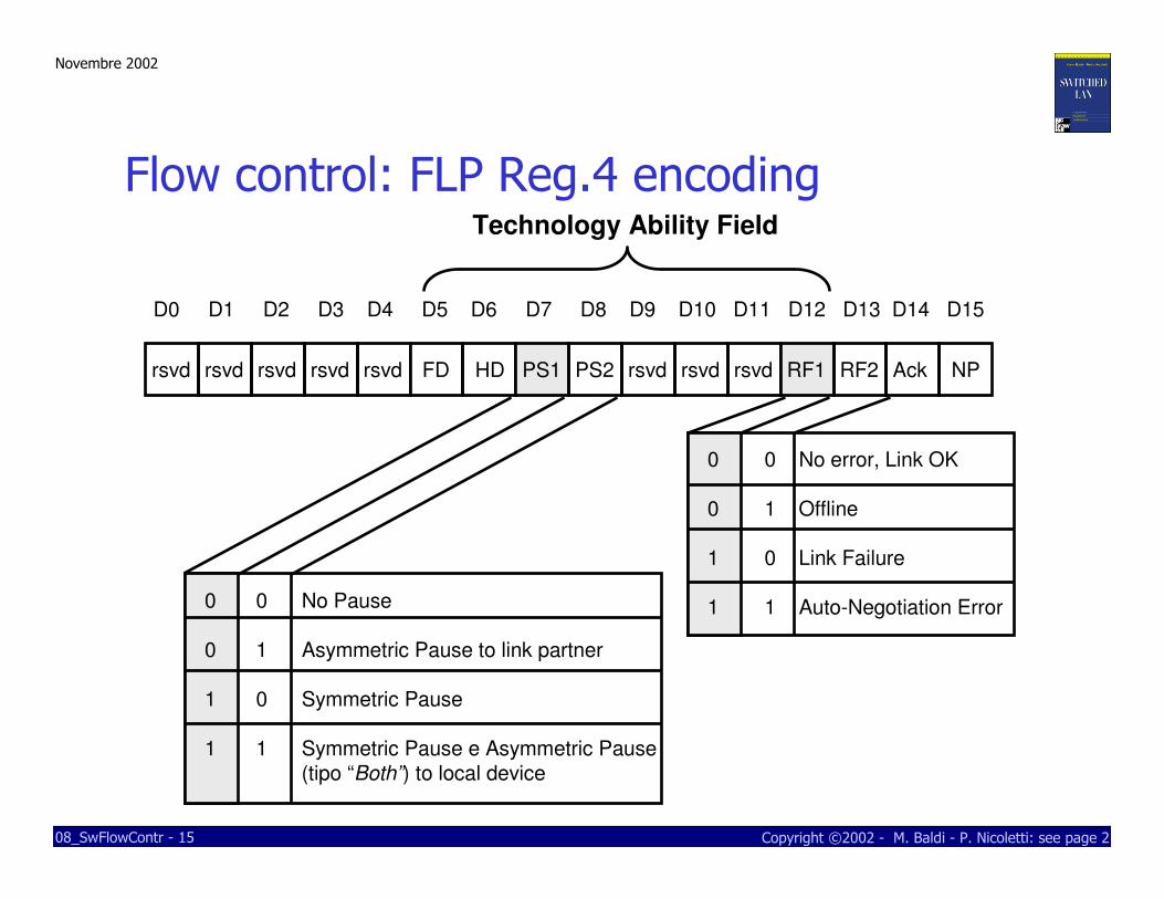
© M. Baldi: see page 2Copyright ©2002 - M. Baldi - P. Nicoletti: see page 208_SwFlowContr - 15
rsvd rsvd rsvd rsvd rsvd FD HD PS1 PS2 rsvd rsvd rsvd RF1 RF2 Ack NP
D0 D1 D2 D3 D4 D5 D6 D7 D8 D9 D10 D11 D12 D13 D14 D15
0 0 No Pause
0 1 Asymmetric Pause to link partner
1 0 Symmetric Pause
1 1 Symmetric Pause e Asymmetric Pause (tipo “Both”) to local device
0 0 No error, Link OK
0 1 Offline
1 0 Link Failure
1 1 Auto-Negotiation Error
Technology Ability Field
Flow control: FLP Reg.4 encoding

Novembre 2002
© M. Baldi: see page 2Copyright ©2002 - M. Baldi - P. Nicoletti: see page 208_SwFlowContr - 16
Bit(s) Name Description Default R/W
15 Next Page Constant 0 = page transmissione with primary capacity 0 RO
14 Reserved Reserved. Must be set to 0 0 RO
13 Remote Fault 1 = malfunctioninig at link’s opposite side 0 RW0 = nessun malfunzionamento
12:5 Technology Ability 8 bit field containing info on tecnologies’ specific 00101111 RWField functionalities identified by selector field
4:0 Selector Field 5 bit field which identifies the kind of message 00001 ROsended for the negotiation. In the Intel 82559 circuiterythis field is read-only and contains 00001b valuewhich stand for IEEE 802.3 standard.
Register 4: Auto-Negotiation Advertisement Register
Flow control: FLP Reg.4 encoding

Novembre 2002
© M. Baldi: see page 2Copyright ©2002 - M. Baldi - P. Nicoletti: see page 208_SwFlowContr - 17
0 0 Don’t Don’t Disable PAUSE Disable PAUSE
care care TX & RX TX & RX
0 1 0 Don’t Disable PAUSE Disable PAUSE
care TX & RX TX & RX
0 1 1 0 Disable PAUSE Disable PAUSE
TX & RX TX & RX
0 1 1 1 Enable PAUSE TX Enable PAUSE RX
Disable PAUSE RX Disable PAUSE TX
1 0 0 Don’t Disable PAUSE Disable PAUSE
care TX & RX TX & RX
1 Don’t care 1 Don’t care Enable PAUSE Enable PAUSE
TX & RX TX & RX
1 1 0 0 Disable PAUSE Disable PAUSE
TX & RX TX & RX
1 1 0 1 Enable PAUSE RX Enable PAUSE TX
Disable PAUSE TX Disable PAUSE RX
Local Device Link Partner
Bit - PS1 Bit - PS2 Bit - PS1 Bit - PS2
Local Device
resolution
Link Partner
resolution
Asymmetric Pause Both Sym & Asym PauseAsymmetric Pause
Symmetric or Both
Asymmetric PAUSE
Symmetric or Both
Both Sym & Asym Pause Asymmetric PAUSE

Novembre 2002
© M. Baldi: see page 2Copyright ©2002 - M. Baldi - P. Nicoletti: see page 208_SwFlowContr - 18
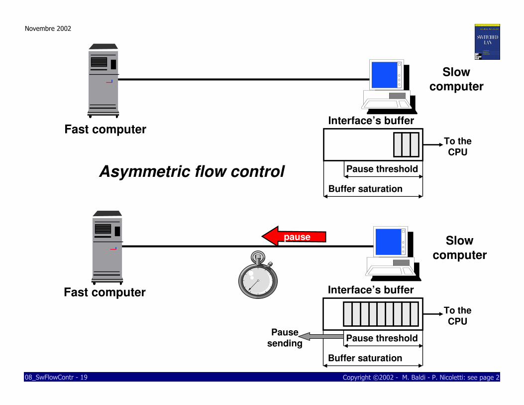
Switch’s flow control: output buffer
� Switch with output buffer and input port connection
� output buffer saturation cause the sending of Pause on input port linked with traffic flow
� solution not implemented by vendors because has more drawback than benefit
� Pause packet on link between two switches penalize also the traffic flows which don’t congest output buffers
� Vendors’ solution:
� switch blocks transmission on port if it receive the Pause packet, but it can’t send the pause packet
Novembre 2002
© M. Baldi: see page 2Copyright ©2002 - M. Baldi - P. Nicoletti: see page 208_SwFlowContr - 19
Interface’s buffer
To the CPU
Pause threshold
Buffer saturation
Interface’s buffer
Pause threshold
Buffer saturation
Pause sending
To the CPU
pause
Fast computer
Fast computer
Asymmetric flow control
Slow
computer
Slow computer

Novembre 2002
© M. Baldi: see page 2Copyright ©2002 - M. Baldi - P. Nicoletti: see page 208_SwFlowContr - 20
Interface’s buffer
Pause threshold
Buffer saturation
Pause sending
To the CPU
pause
Symmetric flow control
Interface’s buffer
Pause threshold
Buffer saturation
Pause sending
To the CPU
pause

Novembre 2002
© M. Baldi: see page 2Copyright ©2002 - M. Baldi - P. Nicoletti: see page 208_SwFlowContr - 21
2
1 4
3
100 Mb/s
100 Mb/s
Sym. or Both Pause
Sym. or Both Pause
Sym. or Both Pause
Sym. or Both Pause
Symmetric flow controlPC-7
PC-8
PC-5

Novembre 2002
© M. Baldi: see page 2Copyright ©2002 - M. Baldi - P. Nicoletti: see page 208_SwFlowContr - 22
2
1 4
3
Output Buffer port 4
Interface’s buffer
To the CPU
Pause threshold
Buffer saturation
100 Mb/s
100 Mb/s
Pause threshold
Buffer saturation
PC-7
PC-8
PC-5

Novembre 2002
© M. Baldi: see page 2Copyright ©2002 - M. Baldi - P. Nicoletti: see page 208_SwFlowContr - 23
2
1 4
3
Pause
Interface’s buffer
Pause threshold
Buffer saturation
Pause sending
To the CPU
100 Mb/s
100 Mb/s
Output Buffer port 4
Pause threshold
Buffer saturationPC-7
PC-8
PC-5

Novembre 2002
© M. Baldi: see page 2Copyright ©2002 - M. Baldi - P. Nicoletti: see page 208_SwFlowContr - 24
2
1 4
3
Interface’s buffer
Pause threshold
Buffer saturation
To the CPU
100 Mb/s
100 Mb/s
Output Buffer port 4
Pause threshold
Buffer saturation
PC-7
PC-8
PC-5

Novembre 2002
© M. Baldi: see page 2Copyright ©2002 - M. Baldi - P. Nicoletti: see page 208_SwFlowContr - 25
2
1 4
3
Pause
Buffer Interfaccia
Pause threshold
Buffer saturation
Pause sending
To the CPU
100 Mb/s
100 Mb/s
Output Buffer port 4
Pause threshold
Buffer saturationPC-7
PC-8
PC-5

Novembre 2002
© M. Baldi: see page 2Copyright ©2002 - M. Baldi - P. Nicoletti: see page 208_SwFlowContr - 26
2
1 4
3
Interface’s buffer
Pause threshold
Buffer saturation
To the CPU
100 Mb/s
100 Mb/s
Output Buffer port 4
Pause threshold
Buffer saturation
Pause sending
Pause
PC-7
PC-8
PC-5

Novembre 2002
© M. Baldi: see page 2Copyright ©2002 - M. Baldi - P. Nicoletti: see page 208_SwFlowContr - 27
2
1 4
3
Interface’s buffer
Pause threshold
Buffer saturation
To the CPU
100 Mb/s
100 Mb/s
Output Buffer port 4
Pause threshold
Buffer saturation
PC-7
PC-8
PC-5

Novembre 2002
© M. Baldi: see page 2Copyright ©2002 - M. Baldi - P. Nicoletti: see page 208_SwFlowContr - 28
2
1 4
3
Interface’s buffer
Pause threshold
Buffer saturation
To the CPU
100 Mb/s100 Mb/s
PC-7
PC-8
PC-5
Interface’s buffer
Pause threshold
Buffer saturation
To the CPU

Novembre 2002
© M. Baldi: see page 2Copyright ©2002 - M. Baldi - P. Nicoletti: see page 208_SwFlowContr - 29
Slow station
Asym. Pause
Both Pause
Sym. or Both Pause
Sym. or Both Pause
Sym. or Both PauseSym. or Both Pause Sym. or Both Pause
Sym. or Both Pause
Fast station
Slow station
Asym. Pause
Both Pause
Symmetric flow control
Asymmetric flow control
Novembre 2002
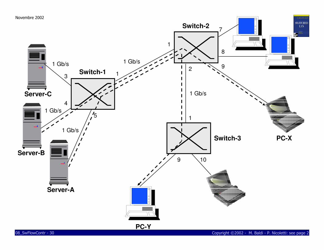
© M. Baldi: see page 2Copyright ©2002 - M. Baldi - P. Nicoletti: see page 208_SwFlowContr - 30
1
1
3
4
5
7
8
92
1
9
Server-A
PC-X
Server-B
PC-Y
Server-C
1 Gb/s
1 Gb/s
1 Gb/s
1 Gb/s
1 Gb/s
10
Switch-1
Switch-2
Switch-3

Novembre 2002
© M. Baldi: see page 2Copyright ©2002 - M. Baldi - P. Nicoletti: see page 208_SwFlowContr - 31
1
1
3
4
5
7
8
92
1
9
Server-A
PC-X
Server-B
PauseServer-C
PC-Y
1 Gb/s
1 Gb/s
1 Gb/s
1 Gb/s
1 Gb/s
10
Switch-1
Switch-2
Switch-3

Novembre 2002
© M. Baldi: see page 2Copyright ©2002 - M. Baldi - P. Nicoletti: see page 208_SwFlowContr - 32
1
1
3
4
5
7
8
92
1
9
Server-A
PC-X
Server-B
Pause
Server-C
PC-Y
1 Gb/s
1 Gb/s
1 Gb/s
1 Gb/s
1 Gb/s
10
Switch-1
Switch-2
Switch-3
Blocks all flows!

Novembre 2002
© M. Baldi: see page 2Copyright ©2002 - M. Baldi - P. Nicoletti: see page 208_SwFlowContr - 33
Flow control on switch with input buffer
� If an input buffer met is saturation because of input portcongestion, it send a Pause packet in the concernedport
� If switching matrix is blocking
� If exist contention on output ports
� No output buffer
� Output buffer are full
� If switching matrix is congested, the event unleash the sending of Pause packet on all ports
� Pause packet sending occurs only on switch with blockingmatrix

Novembre 2002
© M. Baldi: see page 2Copyright ©2002 - M. Baldi - P. Nicoletti: see page 208_SwFlowContr - 34
1
1
3
4
5
7
8
92
1
9 10
Server-A
PC-X
Server-B
Server-C
PC-Y
1 Gb/s
1 Gb/s
1 Gb/s
1 Gb/s
1 Gb/s
Symmetric flowcontrol
Switch-1
Switch-2
Switch-3

Novembre 2002
© M. Baldi: see page 2Copyright ©2002 - M. Baldi - P. Nicoletti: see page 208_SwFlowContr - 35
1
1
3
4
5
7
8
92
1
9 10
Server-A
PC-X
Server-B
Server-C
PC-Y
1 Gb/s
1 Gb/s
1 Gb/s
1 Gb/s
1 Gb/s
Symmetricflow control
Switch-1
Switch-2
Switch-3
Saturat.
Input Buffer port 1
Pau
se

Novembre 2002
© M. Baldi: see page 2Copyright ©2002 - M. Baldi - P. Nicoletti: see page 208_SwFlowContr - 36
1
1
3
4
5
7
8
92
1
9 10
Server-A
PC-X
Server-B
Server-C
PC-Y
1 Gb/s
1 Gb/s
1 Gb/s
1 Gb/s
1 Gb/s
Switch-1
Switch-2
Switch-3
Pause
Pause
Pause

Novembre 2002
© M. Baldi: see page 2Copyright ©2002 - M. Baldi - P. Nicoletti: see page 208_SwFlowContr - 37
Realistical approach on switch with output buffer
� Asymmetric flow control is enabled only on switch-station connections
�make up temporary congestions on input buffers of station’s network interfaces
� not an ideal solution, but can be a good deal in certaintraffic condition

Novembre 2002
© M. Baldi: see page 2Copyright ©2002 - M. Baldi - P. Nicoletti: see page 208_SwFlowContr - 38
1
1
3
4
5
7
8
92
1
9 10
Server-A
PC-X
Server-B
Server-C
PC-Y
1 Gb/s
1 Gb/s
1 Gb/s
1 Gb/s
1 Gb/s
Asymmetric flowcontrol
No Flowcontrol
Switch-1
Switch-2
Switch-3
Asymmetric flowcontrol
Asymmetricflow control