flps and flpv series
TRANSCRIPT
FLPS and FLPV Series
I S O M 1 0 0 Installation, Safety, Operating, & Maintenance Instructions
INSTALLATION, SAFETY, OPERATING, AND MAINTENANCE INSTRUCTIONS
Ex d ATEX - Float Operated Level Switches
IMPORTANT SAFETY INSTRUCTIONS INCLUDED PLEASE READ ALL SECTIONS BEFORE USE
Atex Certificate number: SIRA 17ATEX1236
Page 1
These Float operated switches will be marked as follows:
Electrical Rating 10VASerial Number (see marking on enclosure)
Please contact Cynergy3 before use, should the marking on the enclosure be missing.
Max Process Temp 79ºC
Year of Manufacture
0518TAV, Cynergy3, Wimborne, Dorset, BH21 7PE
II 1 / 2 G DEx db IIB T6 Ga/GbEx tb IIIB T85ºC Db
Max Process 10 barg
1 - General Description
These Float Operated switches use reed switches, where the electrical SPST contacts are contained within a hermetically sealed glass envelope. They are designed to be operated with the float moving vertically up and down. The encapsulated internal reed switch is operated by the movement of the float and cannot be serviced by the user. Should a failure occur the float switch should be returned to Cynergy3 Components for replacement or repair; no repairs should be carried out by the user.
Switching voltage max: 200Vac / 120Vdc
Please contact Cynergy3 Components for advice if your circuit is inductive or capacitive.
The figures shown are the maximum values, for a purely resistive load.
Switching current max: 0.4A
Reed switches are extremely reliable components, when used within their specified electrical rating, so please note the maximum electrical ratings:- Switching power max: 10VA
Minimum fluid SG: 0.80
These hazardous area switches are identified by typical part numbers FLPVAXXBXXX & FLPSAXXBXXX etc.
The electrical connections are made via a 300cm long cable at the top of the device.
All external surfaces of the device are manufactured from stainless steel grade 316L. The central stem contains the fully insulated wiring and reed switch(es), which is supported by silicone rubber within the stem.
These switches are designed for use in Zones 1 & 2
The unit is designed in accordance with the ATEX directive; for the relevant BS:EN standards, see the Declaration of Conformity supplied with the device. It is intended that the device will be fitted to the top or side of the tank being sensed.
Revision AE (ECN 8668 18/10/2019)
ISO9001CERT IF I ED
Cynergy3 Components Ltd. 7 Cobham Road, Ferndown Industrial Estate, Wimborne, Dorset, BH21 7PE, United KingdomTelephone: +44 (0)1202 897969 Email: [email protected] Website: www.cynergy3.com
2
2.1
2.2
2.3
2.4
3.1
3.2
3.3
3.4
3.5
3.6
3.7
3.8
3
Cynergy3 recommends that all TAV brand level switches, used for high level alarm and fitted with either SPST reed switches, are wired to break on rising level.
Installation
Appropriate devices are available to identify both short and open circuit conditions in the external wiring to the switch. Any assessment of the use and application of such devices should always be undertaken by a competent individual.
It is essential that any installation or maintenance work is carried out by a competent individual.
No adjustment can be made to these devices themselves. The cable gland/nut must not be opened/removed.
The user should ensure that no static build up occurs during installation, including in non metallic parts.
The device should be installed using a suitable gasket, which is compatible with the application fluids. Check that there are no leaks, following installation.
The switch should be checked, prior to any installation or adjustment, for any damage to the following items: float, switch stem and cable.
All installation and maintenance work should be assessed by a suitably competent individual with regard to the specific hazards presented by the local environment, to the relevant national codes of practice and the application of the Cynergy3 device.
There are no known hazardous materials contained within Cynergy3 float switches, when used as directed. Please request document WI-202 for details of materials used.
IMPORTANT SAFETY NOTES
WARNING - DO NOT CARRY OUT ANY WORK WITH THE DEVICE ENERGISED.
Hazardous Materials
WARNING - The user should not carry out any modification or fit any non approved parts, as this will invalidate the ATEX certification.
Devices that will be subjected to heavy vibration should be supported within the tank. Do not use these devices, where the vibration levels could exceed 3g horizontal, without consulting Cynergy3 Components.
Corrosion
These devices may only be used in pressure applications of up to 10barg which must not be exceeded. Do not carry out any modifications to the device.
Pressure Applications
These wetted parts of these devices are manufactured from stainless steel 316L. Ensure that the materials are compatible with the fluid(s) being measured. Contact Cynergy3 Components if in doubt about this.
Vibration
The end user must protect the system against overpressure and, before opening any pressure retaining joint, the pressure must be reduced to atmospheric. The fitting of flange mounted devices requires suitable pressure retaining bolting, with sufficient torque to meet the flange standard being used. The torque required for screwed entry devices will depend on the gaskets and sealant used, therefore enough torque should be applied to prevent system leakage. Please contact Cynergy3 Components, if in doubt about this.
Installation, Safety, Operating, & Maintenance Instructions Page 2
FLPS and FLPV Series
I S O M 1 0 0Revision AE (ECN 8668 18/10/2019)
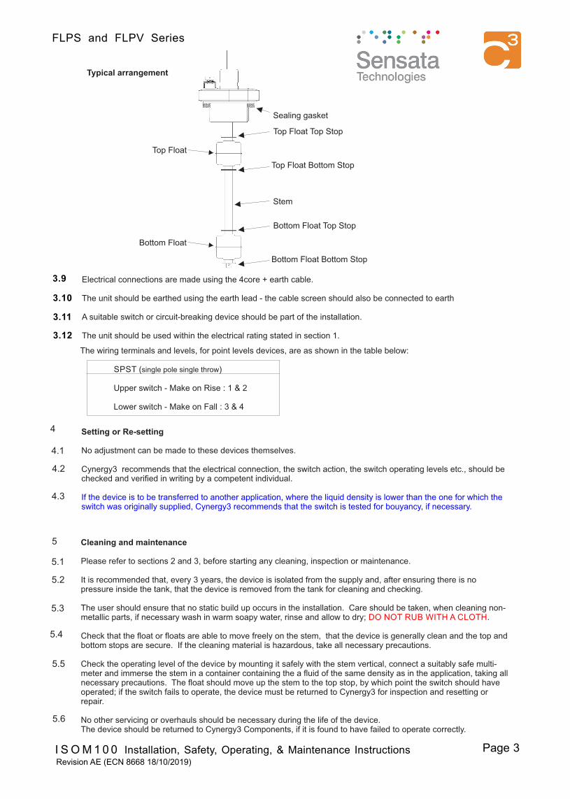
BOTTOM STOP
Installation, Safety, Operating, & Maintenance Instructions Page 3
Stem
Top Float
Bottom Float
Top Float Top Stop
Bottom Float Top Stop
Top Float Bottom Stop
Bottom Float Bottom Stop
No adjustment can be made to these devices themselves.
Cynergy3 recommends that the electrical connection, the switch action, the switch operating levels etc., should be checked and verified in writing by a competent individual.
If the device is to be transferred to another application, where the liquid density is lower than the one for which the switch was originally supplied, Cynergy3 recommends that the switch is tested for bouyancy, if necessary.
Setting or Re-setting
Cleaning and maintenance
Check that the float or floats are able to move freely on the stem, that the device is generally clean and the top and bottom stops are secure. If the cleaning material is hazardous, take all necessary precautions.
Please refer to sections 2 and 3, before starting any cleaning, inspection or maintenance.
Check the operating level of the device by mounting it safely with the stem vertical, connect a suitably safe multi-meter and immerse the stem in a container containing the a fluid of the same density as in the application, taking all necessary precautions. The float should move up the stem to the top stop, by which point the switch should have operated; if the switch fails to operate, the device must be returned to Cynergy3 for inspection and resetting or repair.
It is recommended that, every 3 years, the device is isolated from the supply and, after ensuring there is no pressure inside the tank, that the device is removed from the tank for cleaning and checking.
The user should ensure that no static build up occurs in the installation. Care should be taken, when cleaning non-metallic parts, if necessary wash in warm soapy water, rinse and allow to dry; .DO NOT RUB WITH A CLOTH
No other servicing or overhauls should be necessary during the life of the device.The device should be returned to Cynergy3 Components, if it is found to have failed to operate correctly.
4
4.1
4.2
4.3
5
5.1
5.2
5.3
5.4
5.5
5.6
The unit should be earthed using the earth lead - the cable screen should also be connected to earth
A suitable switch or circuit-breaking device should be part of the installation.
Electrical connections are made using the 4core + earth cable.
The unit should be used within the electrical rating stated in section 1.
3.9
3.10
3.11
3.12
Upper switch - Make on Rise : 1 & 2
SPST (single pole single throw)
Lower switch - Make on Fall : 3 & 4
The wiring terminals and levels, for point levels devices, are as shown in the table below:
FLPS and FLPV Series
I S O M 1 0 0
Typical arrangement
Sealing gasket
Revision AE (ECN 8668 18/10/2019)
Possible Failure Modes Control Method
Cotter pin failure Check during maintenance - see section 5
Device wiring open circuit Wire switch to Break on Alarm - the alarm will activate if switch is open circuit
Customer wiring open circuit Wire switch to Break on Alarm - the alarm will activate if wire breaks
Customer wiring short circuit A competent individual should evaluate risks and use suitable fault detection
Float detached Wire switch to Break on Alarm - the alarm will activate if float detaches
Magnet failure in SPST device Wire switch to Break on Alarm - the alarm will activate if magnet fails
Device wiring closed circuit Check during maintenance - see section 5
Float failed or leaking Check during maintenance - see section 5
equipment, if necessary.
Spares
If the device is damaged, components of the device have moved or non approved parts have been fitted to the device, return to for inspection.Cynergy3 Components
All TAV brand devices are marked with a unique 6 digit BIN number on the enclosure label.
No spare parts are available for these items.
6
6.1
6.2
6.3
6.4
6.5
The contacts within the device will operate on rising or falling liquid level and should operate within ±3mm of their original set levels.
WARNING - The user should not carry out any modification or fit any non approved parts, as this will invalidate the ATEX certification.
Cynergy3 recommends that a competent person should assess the conditions of use and set appropriate intervals for periodic inspection and maintenance to be implemented by the user.
A list of possible device failure modes is listed and methods to control them is shown below:
Exd cable gland must not be opened or tampered with by the user.
Operation
Installation, Safety, Operating, & Maintenance Instructions Page 4
FLPS and FLPV Series
I S O M 1 0 0Revision AE (ECN 8668 18/10/2019)
Notification No. SIRA 02 ATEX M200
This certificate remains valid subject to the company maintaining its system to the required standards, which will be monitored by CSA. The use of this Certificate and the CSA Certification Mark are subject to the Regulations Applicable to Holders of CSA Certificates
CSA Group Netherlands B.V., Utrechtseweg 310, 6812 AR, Arnhem, Netherlands.
DQD507.24 Issue Date: 2018-04-20
1 PRODUCTION/PRODUCT QUALITY ASSURANCE NOTIFICATION
2 Equipment and protective systems intended for use in potentially explosive atmospheres Directive 2014/34/EU
Conformity to Type based on Quality Assurance of the Production Process/Product Quality Assurance
3 Notification No. SIRA 02 ATEX M200
4 Equipment, protective system or components as listed: Switchgear, Contactors, Starters, Circuit Breakers Instrumentation, Measurement and Control Equipment Sensors, Transducers and Signalling Switches
Intrinsic Safety (ia,ib) Flameproof (d) Dust Ignition Protection by Enclosure (t)
5 Manufacturer or
Authorised Representative:
6 Manufacturing locations: As above
7 CSA Group Netherlands B.V. (CSA), Notified Body No. 2813, in accordance with Article 17 of the Council Directive 2014/34/EU, notifies that the manufacturer has a quality system which complies with the requirements of Annexes IV & VII of Directive 2014/34/EU.
8 This notification is based upon Report No. 70211864 issued on 22 January 2019. This notification can be withdrawn if the manufacturer no longer satisfies the requirements of Annexes IV/VII. Results of periodical assessment of the quality system form part of this notification.
9 According to Article 16 [3] of Directive 2014/34/EU the CE marking shall be followed by the identification number 2813 of CSA Group Netherlands B.V. as the Notified Body involved in the production control stage.
Date of Initial Certification: 24 September 2002
James May On behalf of CSA
Date of Issue: 20 February 2019 Date of Expiry: 22 March 2022
Cynergy3 Components Limited 7 Cobham Road Ferndown Industrial Estate Wimborne Dorset BH21 7PE
Project Number 0467 Signed:
Title: Director of Operations
This certificate and its schedules may only be CSA Group Netherlands B.V.
reproduced in its entirety and without change Utrechtseweg 310,
6812 AR, Arnhem,
Netherlands
Page 1 of 2 DQD 544.09 Rev 2018-04-20
1 EU-TYPE EXAMINATION CERTIFICATE 2 Equipment intended for use in Potentially Explosive Atmospheres Directive 2014/34/EU 3 Certificate Number: Sira 17ATEX1236 Issue: 1 4 Equipment: FLPV and FLPS Float Switches 5 Applicant: Cynergy3 Components Ltd. 6 Address: 7 Cobham Road
Ferndown Industrial Estate Wimborne Dorset BH21 7PE UK
7 This equipment and any acceptable variation thereto is specified in the schedule to this certificate and
the documents therein referred to. 8 CSA Group Netherlands B.V., notified body number 2813 in accordance with Articles 17 and 21 of
Directive 2014/34/EU of the European Parliament and of the Council, dated 26 February 2014, certifies that this equipment has been found to comply with the Essential Health and Safety Requirements relating to the design and construction of equipment intended for use in potentially explosive atmospheres given in Annex II to the Directive.
The examination and test results are recorded in the confidential reports listed in Section 14.2. 9 Compliance with the Essential Health and Safety Requirements, with the exception of those listed in the
schedule to this certificate, has been assured by compliance with the following documents:
EN 60079-0:2012/A11:2013 EN 60079-1:2015 EN 60079-26:2015 EN 60079-31:2014 EN 13463-1:2009
10 If the sign ‘X’ is placed after the certificate number, it indicates that the equipment is subject to Specific
Conditions of Use identified in the schedule to this certificate. 11 This EU-Type Examination Certificate relates only to the design and construction of the specified
equipment. If applicable, further requirements of this Directive apply to the manufacture and supply of this equipment.
12 The marking of the equipment shall include the following:
II 1/2 GD Ex db IIB T6 Ga/Gb Ex tb IIIB T85°C Db Tamb = -20°C to +79°C IP66
SCHEDULE
EU-TYPE EXAMINATION CERTIFICATE Sira 17ATEX1236 Issue 1
This certificate and its schedules may only be reproduced in its entirety and without change
CSA Group Netherlands B.V. Utrechtseweg 310, 6812 AR, Arnhem Netherlands
DQD 544.09 Rev 2018-04-20 Page 2 of 2
13 DESCRIPTION OF EQUIPMENT
The FLPV and FLPS Float Switches are reed switch operated devices, the electrical SPST (single pole, single throw) contacts being contained within a hermetically sealed glass envelope. The reed switches are insulated with heat shrink sleeving and fully encapsulated within a tubular stem using silicone rubber.
The encapsulated reed switch is operated by a magnet carried within a float assembly that moves up and down the stem.
Maximum length of product is limited to 500 mm so no switching level may exceed this.
The equipment comprises reed switches operated by external floating magnet closing contacts, intended for use with voltages of up to 200 V AC/120 V DC, no greater than 0.4 A and a maximum permitted power value of 10 VA.
This product range is intended for use with any liquids that are not corrosive to stainless steel 316L, that have a minimum specific gravity of 0.80, a process temperature range of -20oC to +79oC and a maximum pressure of 10 barg.
This product range orporates an integral cable arrangement; it is supplied fully assembled and does not require the end user to open the enclosure during the life of the product.
14 DESCRIPTIVE DOCUMENTS 14.1 Drawings
Refer to Certificate Annexe. 14.2 Associated Sira Reports and Certificate History
Issue Date Report number Comment 0 04 June 2018 R70075123A The release of the prime certificate. 1 15th October 2019 0467 · Transfer of certificate Sira 17ATEX1236 from
Sira Certification Service to CSA Group Netherlands B.V..
15 SPECIFIC CONDITIONS OF USE (denoted by X after the certificate number) None 16 ESSENTIAL HEALTH AND SAFETY REQUIREMENTS OF ANNEX II (EHSRs) The relevant EHSRs that are not addressed by the standards listed in this certificate have been identified
and individually assessed in the reports listed in Section 14.2.
Certificate Annexe
Certificate Number: Sira 17ATEX1236 Equipment: FLPV and FLPS Float Switches Applicant: Cynergy3 Components Ltd.
This certificate and its schedules may only be CSA Group Netherlands B.V.
reproduced in its entirety and without change Utrechtseweg 310,
6812 AR, Arnhem,
Netherlands DQD 544.09 Rev 2018-04-20 Page 1 of 1
Issue 0 Drawing Sheets Rev. Date(Sira stamp) Title
2002 1 of 3 AA 14 May 18 Floatswitch Head, Stem and assembly switch design
2002 2 of 3 AA 20 Sept 17 Floatswitch Flange Accessory Assembly Layout
2002 3 of 3 AA 20 Sept 17 Floatswitch Device Head, Stem and Switch Assembly - Marking
DT1071/FLP 1 of 1 AA 20 Sept 17 G1.25 h Thread Boss FLP