fluid power systems for mobile applications – with a - diva portal
TRANSCRIPT

Linköping Studies in Science and Technology.Thesis No. 1595
Fluid Power Systems for Mobile
Applications
with a Focus on Energy Efficiency and DynamicCharacteristics
Mikael Axin
LIU-TEK-LIC-2013:29Division of Fluid and Mechatronic Systems
Department of Management and EngineeringLinköping University, SE–581 83 Linköping, Sweden
Linköping 2013

ISBN 978-91-7519-600-8ISSN 0280-7971LIU-TEK-LIC-2013:29
Copyright c© 2013 by Mikael AxinDepartment of Management and EngineeringLinköping UniversitySE-581 83 Linköping, Sweden
Printed in Sweden by LiU-Tryck, Linköping, 2013.

To Jennie
”Mycket få människor lever i dag – de
flesta gör förberedelser för att leva i
morgon.
Jonathan Swift (1667-1745)

”Att inse att man är okunnig är ett bra
steg mot kunskap.
Benjamin Disraeli (1804-1881)
Abstract
This thesis studies an innovative working hydraulic system design formobile applications. The purpose is to improve the energy efficiency andthe dynamic characteristics compared to load sensing systems withoutincreasing the complexity or adding additional components.
The system analysed in this thesis is referred to as flow control. Thefundamental difference compared to load sensing systems is that thepump is controlled based on the operator’s command signals rather thanfeedback signals from the loads. This control approach enables higherenergy efficiency since the pressure difference between pump and load isgiven by the system resistance rather than a prescribed pump pressuremargin. High power savings are possible especially at medium flow rates.
Furthermore, load sensing systems suffer from poor dynamic charac-teristics since the pump is operated in a closed loop control mode. Thismight result in an oscillatory behaviour. Flow control systems have nostability issues attached to the load pressure feedback since there is none.
Pressure compensators are key components in flow control systems.This thesis addresses the flow matching problem which occurs whenusing conventional compensators in combination with a flow controlledpump. Flow sharing pressure compensators solve this problem since thepump flow will be distributed between all active functions. A novel con-trol approach where the directional valve is controlled without affectingthe cylinder velocity with the objective of optimizing the damping isproposed.
In this research, both theoretical studies and practical implementa-tions demonstrate the capability of flow control systems. Experimentsshow a reduced pump pressure margin and energy saving possibilities ina short loading cycle for a wheel loader application.
i

ii

Acknowledgements
The work presented in this thesis has been carried out at the Divisionof Fluid and Mechatronic Systems (Flumes) at Linköping University.There are several people who have made this thesis possible and towhom I would like to express my gratitude.
First of all I would like to thank my supervisor, Prof. Petter Krus, forhis support, supervision and valuable inputs to my work. I am also verygrateful to Prof. Jan-Ove Palmberg, former head of division. Thankyou for giving me the opportunity to be a part of this division. I wouldlike to give special thanks to Dr. Björn Eriksson for his great support inmy work. I would also like to thank all my other colleagues for makingthe university a fun place to work at.
Thanks go to Parker Hannifin AB for their financial involvement andtheir help with hardware and other resources.
Most of all, I would like to thank my family and friends for alwaysbeing there for me. My greatest gratitude goes to you Jennie, my won-derful love, for sharing life with me.
Linköping, April, 2013
Mikael Axin
iii

iv
Papers
The following three appended papers are arranged in chronological orderof publication and will be referred to by their Roman numerals. Allpapers are printed in their originally published state with the exceptionof minor errata and changes in text and figure layout in order to maintainconsistency throughout the thesis.
In papers [I], [II] and [III], the first author is the main author, respon-sible for the work presented, with additional support from the co-writers.A short summary of each paper can be found in chapter 8.
[I] M. Axin, B. Eriksson, and J.-O. Palmberg. “Energy Efficient LoadAdapting System Without Load Sensing - Design and Evalu-ation”. In: The 11th Scandinavian International Conference onFluid Power (SICFP’09). Linköping, Sweden, June 2009.
[II] M. Axin, B. Eriksson, J.-O. Palmberg, and P. Krus. “DynamicAnalysis of Single Pump, Flow Controlled Mobile Systems”. In:The Twelfth Scandinavian International Conference on FluidPower (SICFP’11). Vol. 2. Tampere, Finland, May 2011, pp. 223–238.
[III] M. Axin, J.-O. Palmberg, and P. Krus. “Optimized Damping inCylinder Drives Using the Meter-out Orifice - Design and Exper-imental Verification”. In: 8th International Fluid Power Confer-ence (IFK). Vol. 1. Dresden, Germany, Mar. 2012, pp. 579–591.
v

Papers not included
Paper [IV] is not included in the thesis but constitutes an importantpart of the background. The two first authors are the main authors,responsible for the work presented, with additional support from theco-writers.
[IV] M. Axin, R. Braun, A. Dell’Amico, B. Eriksson, P. Nordin, K.Pettersson, I. Staack, and P. Krus. “Next Generation SimulationSoftware using Transmission Line Elements”. In: Fluid Power andMotion Control (FPMC). Bath, UK, Sept. 2010, pp. 265–276.
vi
Contents
1 Introduction 1
1.1 Motivation and Needs . . . . . . . . . . . . . . . . . . . . 1
1.2 Aims . . . . . . . . . . . . . . . . . . . . . . . . . . . . . . 2
1.3 Delimitations . . . . . . . . . . . . . . . . . . . . . . . . . 2
1.4 Contribution . . . . . . . . . . . . . . . . . . . . . . . . . 2
2 Mobile Working Hydraulic Systems 3
2.1 Valve Controlled Systems . . . . . . . . . . . . . . . . . . 4
2.1.1 Open-centre . . . . . . . . . . . . . . . . . . . . . . 4
2.1.2 Constant Pressure . . . . . . . . . . . . . . . . . . 6
2.1.3 Load Sensing . . . . . . . . . . . . . . . . . . . . . 7
2.1.4 Individual Metering . . . . . . . . . . . . . . . . . 9
2.2 Valveless Systems . . . . . . . . . . . . . . . . . . . . . . . 13
2.2.1 Secondary Control using Transformers . . . . . . . 13
2.2.2 Pump Controlled Actuators . . . . . . . . . . . . . 14
2.2.3 Electro Hydraulic Actuators . . . . . . . . . . . . . 15
2.3 System Summary . . . . . . . . . . . . . . . . . . . . . . . 17
3 The Flow Control Concept 19
3.1 Pressure Compensators . . . . . . . . . . . . . . . . . . . 21
3.1.1 Traditional Compensators . . . . . . . . . . . . . . 21
3.1.2 Flow Sharing Compensators . . . . . . . . . . . . . 22
3.2 Pump and Valve Control Approaches . . . . . . . . . . . . 24
3.2.1 Flow Control using Traditional Compensators . . . 24
3.2.2 Flow Control using Flow Sharing Compensators . 26
3.3 Energy Efficiency . . . . . . . . . . . . . . . . . . . . . . . 28
vii
4 Dynamic Analysis 314.1 Mathematical Model . . . . . . . . . . . . . . . . . . . . . 324.2 Pump Stability . . . . . . . . . . . . . . . . . . . . . . . . 34
4.2.1 Load Sensing Systems . . . . . . . . . . . . . . . . 344.2.2 Flow Control Systems . . . . . . . . . . . . . . . . 35
4.3 Damping . . . . . . . . . . . . . . . . . . . . . . . . . . . 374.3.1 Active Control of the Inlet Orifice . . . . . . . . . 374.3.2 Design and Control of the Outlet Orifice . . . . . . 40
5 Experimental Results 435.1 Energy Efficiency Improvements . . . . . . . . . . . . . . 43
5.1.1 Hardware Requirements . . . . . . . . . . . . . . . 435.1.2 A Demonstrator System . . . . . . . . . . . . . . . 44
5.2 Improved Damping . . . . . . . . . . . . . . . . . . . . . . 47
6 Summary and Conclusions 49
7 Outlook 51
8 Review of Papers 53
Appended papers
I Energy Efficient System Without Load Sensing 61
II Dynamic Analysis of Flow Controlled Systems 85
III Optimized Damping Using the Meter-out Orifice 109
viii
Nomenclature
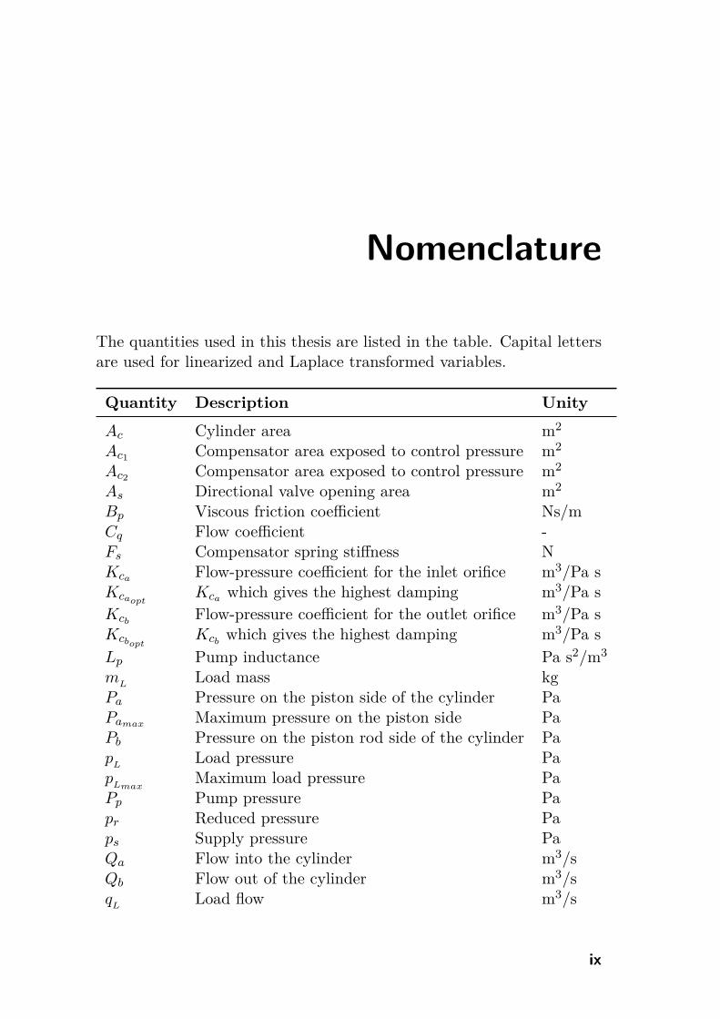
The quantities used in this thesis are listed in the table. Capital lettersare used for linearized and Laplace transformed variables.
Quantity Description Unity
Ac Cylinder area m2
Ac1Compensator area exposed to control pressure m2
Ac2Compensator area exposed to control pressure m2
As Directional valve opening area m2
Bp Viscous friction coefficient Ns/mCq Flow coefficient -Fs Compensator spring stiffness NKca Flow-pressure coefficient for the inlet orifice m3/Pa sKcaopt
Kca which gives the highest damping m3/Pa s
KcbFlow-pressure coefficient for the outlet orifice m3/Pa s
KcboptKcb
which gives the highest damping m3/Pa s
Lp Pump inductance Pa s2/m3
mL
Load mass kgPa Pressure on the piston side of the cylinder PaPamax Maximum pressure on the piston side PaPb Pressure on the piston rod side of the cylinder Pap
LLoad pressure Pa
pLmax
Maximum load pressure PaPp Pump pressure Papr Reduced pressure Paps Supply pressure PaQa Flow into the cylinder m3/sQb Flow out of the cylinder m3/sq
LLoad flow m3/s
ix

Qp Pump flow m3/sQpref
Pump flow demand m3/ss Laplace variable 1/sU Mechanical gear ratio -Va Volume at the piston side of the cylinder m3
Vb Volume at the piston rod side of the cylinder m3
Vp Pump hose volume m3
Xp Piston position mβe Bulk modulus Paγi Parameter for the inlet orifice -γo Parameter for the outlet orifice -δhmax
Maximum damping -Δpp Pump pressure margin PaΔPp Pump pressure margin PaΔPpref
Pump pressure margin demand Paκ Cylinder area ratio -ρ Density kg/m3
Go Open loop transfer functionGpF C
Pump transfer functionGpLS
Pump transfer functionGva Inlet valve transfer functionGvea Inlet valve transfer functionGvb
Outlet valve transfer functionHs Pump hose transfer functionZ
LLoad transfer function
x

1Introduction
Fluid power systems are used in a wide range of applications, mobile aswell as industrial. In mobile machinery, such as construction, forestryand agricultural machines, fluid power is used for both propulsion sys-tems and working hydraulics. An example of working hydraulics is thesystem controlling the bucket motion of an excavator. This thesis coversthe area of working hydraulics in mobile machinery. An innovative sys-tem design is presented and discussed in relation to both existing andnot yet commercially available mobile hydraulic systems.
1.1 Motivation and Needs
There are several different reasons for preferring fluid power systemsto other technologies. Fluid power components have a superior powerdensity compared to other technologies, for example electrical compo-nents [1]. Furthermore, fluid power systems have the ability to handleforce impacts, which makes it more robust than for example mechanicaltransmissions. Fluid power components are generally available at lowercost compared to other technologies, especially for high power applica-tions [1]. Another property of fluid power systems is their good heattransfer capability.
Fluid power systems also present some challenges. The most impor-tant one concerns their energy efficiency [2] [3]. Much progress has beenmade in making the individual components more efficient [4] [5]. How-ever, each component has its own optimum working condition, whichoften leads to poor overall system efficiency [5].
When improving energy efficiency in fluid power systems, the trend
1

Fluid Power Systems for Mobile Applications
is to use additional components and more sophisticated control algo-rithms [2] [6]. Meanwhile, less attention has been paid to the dynamicproperties. A hydraulic system with poor dynamic properties has a ten-dency to oscillate, which has a negative impact on both the productivityof the application and the comfort of the operator.
1.2 Aims
The purpose of this thesis is to investigate and analyse how the energyefficiency and the dynamic characteristics of the working hydraulics inmobile machinery can be improved. Different valve concepts are studied.The hypothesis is that there exist valve controlled systems which im-prove the energy efficiency and the dynamic properties compared to loadsensing systems, without increasing the complexity or adding additionalcomponents. The solutions presented in this thesis are demonstratedthrough both simulation and experiments.
1.3 Delimitations
This thesis concerns the energy efficiency and dynamic characteristicsof mobile fluid power systems. Other aspects, such as manufacturingand marketing are not taken up. Industrial hydraulics and propulsionsystems are not included in this work. The thesis is also limited to thehydraulic system; the combustion engine powering the hydraulic pumpis therefore not included. The field of digital hydraulics is not includedin this thesis.
1.4 Contribution
The most important contribution of this thesis is a deeper understandingof the dynamic characteristics of flow control systems. Novel ways ofdesigning and controlling the directional valves in order to optimize thedamping are proposed and demonstrated. Energy measurements, whereflow control and load sensing systems are compared in a wheel loaderapplication, are performed analytically and verified by experiments.
2

2Mobile Working
Hydraulic Systems
Mobile hydraulic applications distinguish themselves from other hy-draulic applications, such as industrial hydraulics, because the pressureand flow demand varies greatly over time and between different func-tions. Unlike other hydraulic applications, several functions are oftensupplied by one single pump. This means that the total installed poweron the actuator side is generally considerably higher than the installedpump power. This is possible because the actuators almost never requiretheir maximum power at the same time.
Fluid power systems have successfully been used in mobile machinesfor several decades. Because of the machines’ versatility, different hy-draulic systems have been developed for different applications. Impor-tant properties for hydraulic systems are energy efficiency, dynamic char-acteristics and complexity. However, the order of these properties variesfor different applications. The following sections give an overview ofthe most commonly used working hydraulic systems of today. It alsopresents some interesting system designs that have not yet been com-mercialized but are attracting considerable attention both in industry aswell as academia. Energy efficiency, dynamic characteristics and systemcomplexity are discussed and compared.
3
Fluid Power Systems for Mobile Applications
2.1 Valve Controlled Systems
The most common hydraulic systems in mobile machines are systemsbased on valve control. Common to these systems is that they can besupplied by one single pump, which gives a cost effective and compactsystem solution. Four different hydraulic system designs are here cate-gorized by open-centre, constant pressure, load sensing and individualmetering.
2.1.1 Open-centre
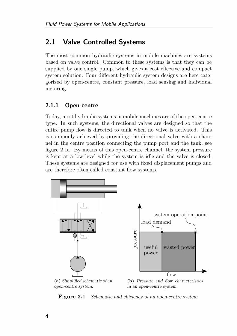
Today, most hydraulic systems in mobile machines are of the open-centretype. In such systems, the directional valves are designed so that theentire pump flow is directed to tank when no valve is activated. Thisis commonly achieved by providing the directional valve with a chan-nel in the centre position connecting the pump port and the tank, seefigure 2.1a. By means of this open-centre channel, the system pressureis kept at a low level while the system is idle and the valve is closed.These systems are designed for use with fixed displacement pumps andare therefore often called constant flow systems.
(a) Simplified schematic of anopen-centre system.
flow
useful wasted powerpre
ssure
power
load demand
system operation point
(b) Pressure and flow characteristicsin an open-centre system.
Figure 2.1 Schematic and efficiency of an open-centre system.
4
Mobile Working Hydraulic Systems
When a valve is shifted from its centre position, the open-centre chan-nel begins to close and the pump pressure increases. Simultaneously,the pump port is connected to either of the load ports, depending onthe direction of spool movement, while the other load port is connectedto tank. When the pump flow is restricted so that the pump pressureis higher than the load pressure, the check valve opens and there willbe a flow to the load. The rate of this flow is thus not only dependenton spool displacement, but also on load pressure. This is called loaddependency.
If several valves are activated simultaneously, the flow to each ac-tuator will not only be dependent on its own load, but also on otheractivated loads. This means that the pressure level at one load canheavily influence the speed of another actuator, a phenomenon calledload interaction.
Another disadvantage of open-centre systems is that the flow is loaddependent. For heavy loads, the major part of the lever stroke is used torestrict the pump flow in order to obtain a high pump pressure. Only aminor part of the stroke is then left for controlling the speed. This mightbe a serious problem if a heavy load is be positioned with accuracy, asis often the case for instance with mobile cranes.
The fact that the flow is load dependent is from a dynamic point ofview actually an advantage. It gives the system a naturally high damp-ing, which means that the system is less prone to oscillations. To obtaindamping from a valve, the flow has to increase when the pressure dropacross the valve increases and vice versa. Damping is a preferred prop-erty when handling large inertia loads, for example the swing functionof a mobile crane.
The most important disadvantage of open-centre systems is that itmay have poor energy efficiency. High energy losses accur when liftingheavy loads slowly; the pump pressure needs to be high but only a minorpart of the flow is directed to the load, see figure 2.1b. Most of the flowis then directed through the open-centre channel to the tank with a highpressure drop, resulting in high energy losses.
To summarize, open-centre systems have the following advantages anddisadvantages:
Advantages The system is simple and robust. It has high damping,which makes it suitable for heavy mobile applications.
Disadvantages Poor overall efficiency and interaction between simul-
5
Fluid Power Systems for Mobile Applications
taneously operated loads. The actuator velocity does not corre-spond to a specific lever displacement but is also a function of theload pressure.
2.1.2 Constant Pressure
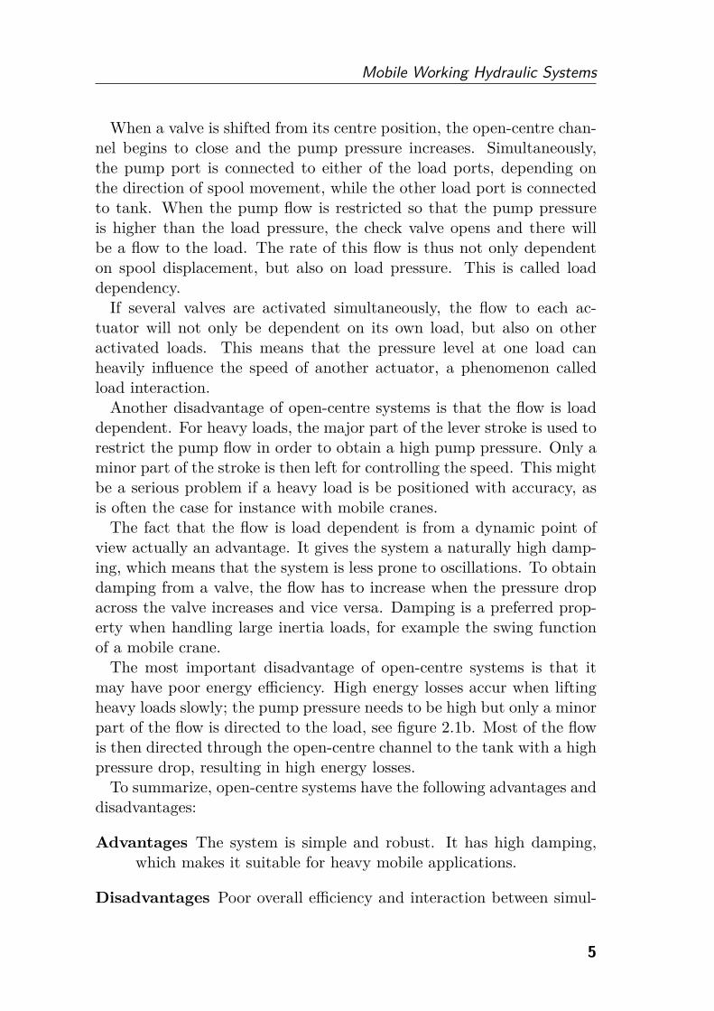
A constant pressure system can be realized using a pressure controlledvariable displacement pump or a fixed pump working against a pressurerelief valve. In this section, the pressure controlled pump solution willbe discussed because of its higher efficiency, see figure 2.2a. When thesystem is idle, each directional valve has a closed pump port and thevariable pump is de-stroked to a small displacement, compensating forits own losses and thus keeping the pressure constant. The directionalvalves are of closed centre type.
(a) Simplified schematic of aconstant pressure system.
useful power
wasted power
flow
pre
ssure
load demand
system operation point
(b) Pressure and flow characteristicsin a constant pressure system.
Figure 2.2 Schematic and efficiency of a constant pressure system.
There is a flow to the actuator when its directional valve is shiftedfrom neutral position. Simultaneously, the pump controller increases itsdisplacement in order to maintain a constant system pressure. The flowrate is dependent on both spool displacement and load pressure. Conse-quently, constant pressure systems suffer from load dependency. How-ever, the controllability of these systems is better than in open-centre
6

Mobile Working Hydraulic Systems
systems as far as interaction between actuators is concerned. This is be-cause there is no dependency between the load pressure and the pumppressure. From a dynamic point of view, constant pressure systems havesimilar characteristics to open-centre systems due to their load depen-dency. The damping is therefore high.
Regarding energy efficiency, constant pressure systems are a goodchoice if the present loads tend to be constant. The pump pressureis then matched against the mentioned constant load. However, if theload situation alters, high losses might occur. This is especially truewhen raising a light load with a high velocity, see figure 2.2b. The mainpart of the entire pressure drop then occurs across the directional valveand only a minor part is used to lift the load. The major fraction of thetotal power is therefore spent in heating the oil. Consequently, these sys-tems not only have large energy losses but also often need extra energyto cool the oil.
Advantages No interaction between simultaneously operated loads anda high damping.
Disadvantages Poor efficiency for light loads and the actuator velocitydoes not correspond to a specific lever displacement but is also afunction of the load pressure.
2.1.3 Load Sensing
Load sensing systems use a variable displacement pump and closed cen-tre valves, similar to constant pressure systems. However, the pump con-troller is designed in a different way. Instead of maintaining a constantpressure, the pump pressure is continuously adapted according to thehighest load, see figure 2.3. Another load sensing system design wouldbe to use a fixed displacement pump and a pressure relief valve, adapt-ing its cracking pressure according to the highest load. That solution,however, is not discussed in this thesis because of its lower efficiency.An early review of load sensing systems was made by Andersson in [7].
When all directional valves are closed, the pump is de-stroked, main-taining a low system pressure. When a valve is shifted from neutralposition, the pump controller senses the load and increases its pressure,thereby allowing a flow to the actuator. Since the pump pressure con-tinuously adapts to the load, a specific lever displacement results in acertain flow, independent of the load pressure.
7

Fluid Power Systems for Mobile Applications
Figure 2.3 Simplified schematic of a load sensing system.
Load sensing systems have no load dependency as long as only oneload is controlled. However, when several loads are operated simultane-ously, only the heaviest load will be load independent. All lighter loadswill suffer from both load dependency and load interaction. In applica-tions where controllability is an important feature, the valves are oftenequipped with pressure compensators. The pressure drop across eachdirectional valve is then kept at a constant level and all functions arethereby load independent and there will be no load interaction. Pressurecompensators are studied in detail in section 3.1.
One weakness of load sensing systems using pressure compensatedvalves is the hydraulic damping. The primary design endeavours toachieve low influence on the flow from the load pressure. This decreasesthe damping capability of the valve. The dynamics of load sensing sys-tems are studied in more detail in chapter 4.
Load sensing systems have high energy efficiency since the pump con-tinuously adapts its pressure just above the highest load. A pressuredifference, usually around 20-30 bar, between pump and load is necess-ary to overcome losses in hoses and valves. This pressure margin is oftenset substantially higher than necessary to ensure it is high enough at alloperational points. More details regarding the pressure margin can befound in section 3.3. When several functions are operated simultane-
8

Mobile Working Hydraulic Systems
ously, high losses might occur at lighter loads. An example is when alight load is operated with a high velocity and a heavier load is activatedat the same time, see figure 2.4.
pre
ssure
flow
useful powerwasted power
useful power
pump pressure margin
load 1
load 2
system operationpoint
Figure 2.4 Pressure and flow characteristics in a load sensing system.
To summarize, pressure compensated load sensing systems have thefollowing advantages and disadvantages:
Advantages Energy efficiency is high although pressure and flow de-mands vary greatly over time and between different functions. Thesystem has excellent controllability since there is no load interac-tion and no load dependency.
Disadvantages Low damping, meaning that the system can show anoscillatory behaviour in certain points of operation. High losses atlighter loads when several functions are operated simultaneously.A needless pressure loss in most points of operation due to anexcessive pressure margin.
2.1.4 Individual Metering
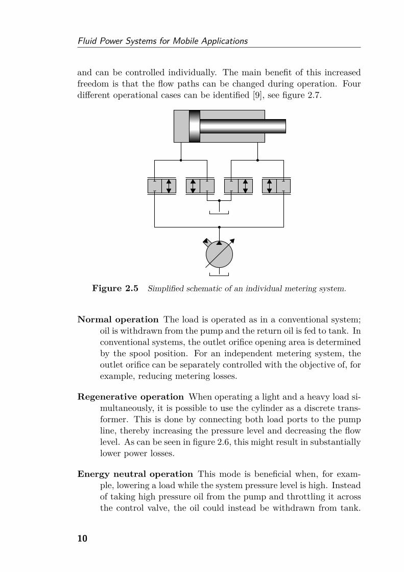
A step forward from load sensing systems using conventional spool valvesis to decouple the inlet and outlet orifices in the valve, see figure 2.5.Numerous configurations for individual metering systems have been de-veloped, both in academia as well as in industry [8]. These conceptsprovide a higher degree of freedom as all four orifices are separated
9
Fluid Power Systems for Mobile Applications
and can be controlled individually. The main benefit of this increasedfreedom is that the flow paths can be changed during operation. Fourdifferent operational cases can be identified [9], see figure 2.7.
Figure 2.5 Simplified schematic of an individual metering system.
Normal operation The load is operated as in a conventional system;oil is withdrawn from the pump and the return oil is fed to tank. Inconventional systems, the outlet orifice opening area is determinedby the spool position. For an independent metering system, theoutlet orifice can be separately controlled with the objective of, forexample, reducing metering losses.
Regenerative operation When operating a light and a heavy load si-multaneously, it is possible to use the cylinder as a discrete trans-former. This is done by connecting both load ports to the pumpline, thereby increasing the pressure level and decreasing the flowlevel. As can be seen in figure 2.6, this might result in substantiallylower power losses.
Energy neutral operation This mode is beneficial when, for exam-ple, lowering a load while the system pressure level is high. Insteadof taking high pressure oil from the pump and throttling it acrossthe control valve, the oil could instead be withdrawn from tank.
10

Mobile Working Hydraulic Systems
No power is then needed from the system pump. The return oil isfed to tank.
Recuperative operation This mode is similar to energy neutral op-eration. However, instead of feeding the return oil to tank, it isdirected into the pump line. The cylinder thus works as a pumpand can be used to drive other loads or operate the system pumpas a motor.
pre
ssure
flow
useful powerload 1
load 2
wasted power
useful power
system operation point
Figure 2.6 It is possible to reduce the losses when using the regenera-
tive operation mode in individual metering systems.
Advantages Possibility to optimize the efficiency by means of changingthe flow paths. Recuperation of energy is possible. Active dampingmeasures are easy to implement because of increased flexibility.
Disadvantages Complex controller and often sensor dependent for flowpath selection.
11

Fluid Power Systems for Mobile Applications
(a) Normal operation, the load isoperated as in a conventional sys-tem.
(b) Regenerative operation, bothload ports are connected to thepump with the objective to even outpressure differences between loads.
(c) Energy neutral operation, a loadcan be lowered without any powerfrom the pump.
(d) Recuperative operation, thecylinder works as a pump enablingenergy recuperation.
Figure 2.7 Flow paths for the different operational cases in individual
metering systems.
12
Mobile Working Hydraulic Systems
2.2 Valveless Systems
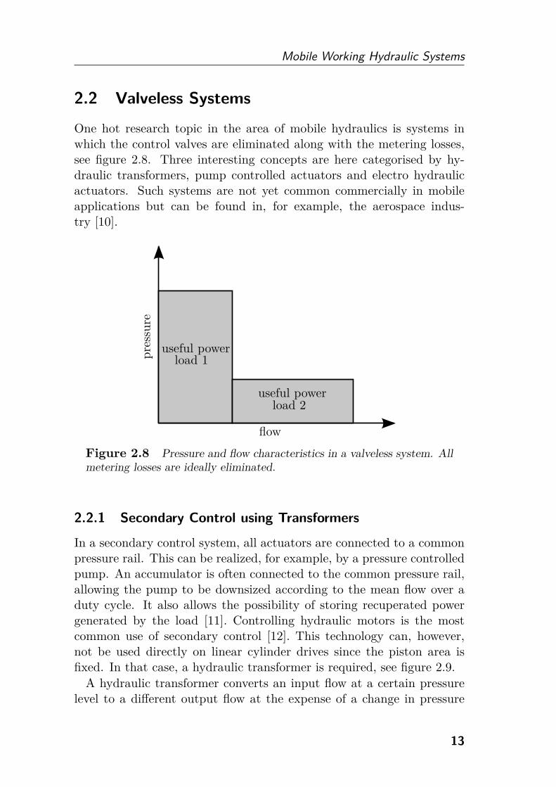
One hot research topic in the area of mobile hydraulics is systems inwhich the control valves are eliminated along with the metering losses,see figure 2.8. Three interesting concepts are here categorised by hy-draulic transformers, pump controlled actuators and electro hydraulicactuators. Such systems are not yet common commercially in mobileapplications but can be found in, for example, the aerospace indus-try [10].
pre
ssure
flow
useful power
useful power
load 1
load 2
Figure 2.8 Pressure and flow characteristics in a valveless system. All
metering losses are ideally eliminated.
2.2.1 Secondary Control using Transformers
In a secondary control system, all actuators are connected to a commonpressure rail. This can be realized, for example, by a pressure controlledpump. An accumulator is often connected to the common pressure rail,allowing the pump to be downsized according to the mean flow over aduty cycle. It also allows the possibility of storing recuperated powergenerated by the load [11]. Controlling hydraulic motors is the mostcommon use of secondary control [12]. This technology can, however,not be used directly on linear cylinder drives since the piston area isfixed. In that case, a hydraulic transformer is required, see figure 2.9.
A hydraulic transformer converts an input flow at a certain pressurelevel to a different output flow at the expense of a change in pressure
13

Fluid Power Systems for Mobile Applications
level, ideally maintaining the hydraulic power. One way of realizing atransformer is to combine two hydraulic machines, where at least one hasa variable displacement. However, the efficiency is limited, mainly be-cause at least one of the machines will operate under partial loading [13].In recent years, an innovative transformer concept has been developedby the Dutch company Innas BV [14]. The conventional transformerwith 2 hydraulic machines has been replaced by one axial piston unit,thereby avoiding partial loading conditions. A mean efficiency of 93%in a broad region of operation has been reported [5].
Figure 2.9 Simplified schematic of a constant pressure system
equipped with transformers and an accumulator, enabling energy recu-
peration.
Advantages High efficiency, even when several loads are operated si-multaneously. Possibility to recuperate energy from the loads.
Disadvantages The number of hydraulic machines is increased, whichmeans more required space and a higher cost. Low damping sincethe flow is load independent.
2.2.2 Pump Controlled Actuators
Instead of using one pump to supply all actuators, each actuator has adedicated pump in pump controlled actuator systems. To control the
14
Mobile Working Hydraulic Systems
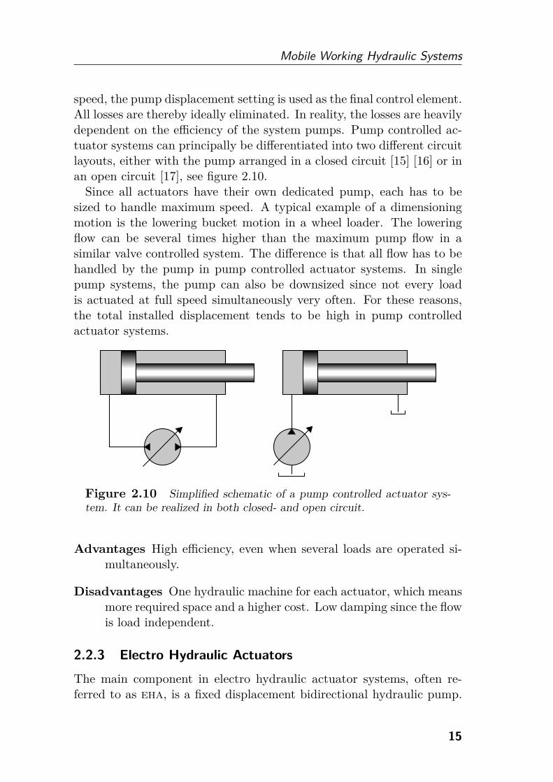
speed, the pump displacement setting is used as the final control element.All losses are thereby ideally eliminated. In reality, the losses are heavilydependent on the efficiency of the system pumps. Pump controlled ac-tuator systems can principally be differentiated into two different circuitlayouts, either with the pump arranged in a closed circuit [15] [16] or inan open circuit [17], see figure 2.10.
Since all actuators have their own dedicated pump, each has to besized to handle maximum speed. A typical example of a dimensioningmotion is the lowering bucket motion in a wheel loader. The loweringflow can be several times higher than the maximum pump flow in asimilar valve controlled system. The difference is that all flow has to behandled by the pump in pump controlled actuator systems. In singlepump systems, the pump can also be downsized since not every loadis actuated at full speed simultaneously very often. For these reasons,the total installed displacement tends to be high in pump controlledactuator systems.
Figure 2.10 Simplified schematic of a pump controlled actuator sys-
tem. It can be realized in both closed- and open circuit.
Advantages High efficiency, even when several loads are operated si-multaneously.
Disadvantages One hydraulic machine for each actuator, which meansmore required space and a higher cost. Low damping since the flowis load independent.
2.2.3 Electro Hydraulic Actuators
The main component in electro hydraulic actuator systems, often re-ferred to as eha, is a fixed displacement bidirectional hydraulic pump.
15
Fluid Power Systems for Mobile Applications
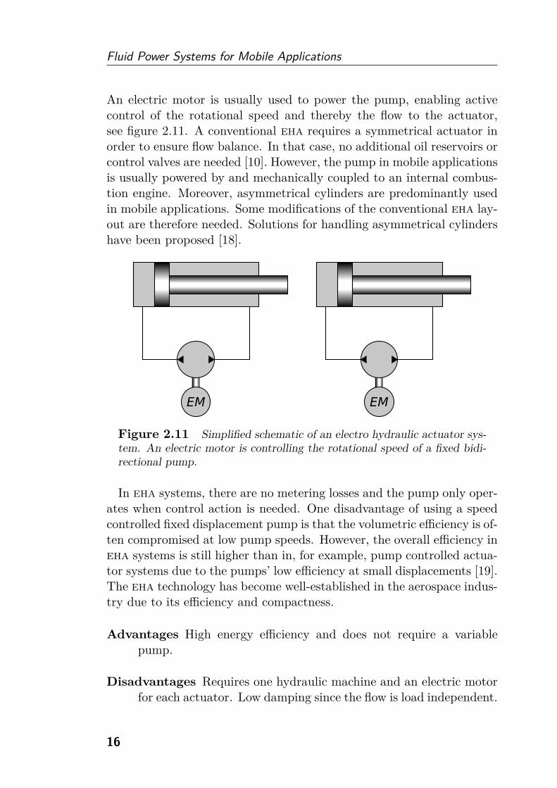
An electric motor is usually used to power the pump, enabling activecontrol of the rotational speed and thereby the flow to the actuator,see figure 2.11. A conventional eha requires a symmetrical actuator inorder to ensure flow balance. In that case, no additional oil reservoirs orcontrol valves are needed [10]. However, the pump in mobile applicationsis usually powered by and mechanically coupled to an internal combus-tion engine. Moreover, asymmetrical cylinders are predominantly usedin mobile applications. Some modifications of the conventional eha lay-out are therefore needed. Solutions for handling asymmetrical cylindershave been proposed [18].
Figure 2.11 Simplified schematic of an electro hydraulic actuator sys-
tem. An electric motor is controlling the rotational speed of a fixed bidi-
rectional pump.
In eha systems, there are no metering losses and the pump only oper-ates when control action is needed. One disadvantage of using a speedcontrolled fixed displacement pump is that the volumetric efficiency is of-ten compromised at low pump speeds. However, the overall efficiency ineha systems is still higher than in, for example, pump controlled actua-tor systems due to the pumps’ low efficiency at small displacements [19].The eha technology has become well-established in the aerospace indus-try due to its efficiency and compactness.
Advantages High energy efficiency and does not require a variablepump.
Disadvantages Requires one hydraulic machine and an electric motorfor each actuator. Low damping since the flow is load independent.
16
Mobile Working Hydraulic Systems
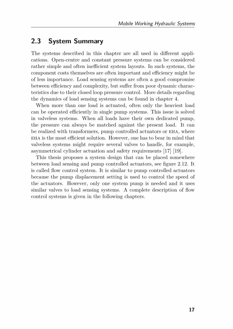
2.3 System Summary
The systems described in this chapter are all used in different appli-cations. Open-centre and constant pressure systems can be consideredrather simple and often inefficient system layouts. In such systems, thecomponent costs themselves are often important and efficiency might beof less importance. Load sensing systems are often a good compromisebetween efficiency and complexity, but suffer from poor dynamic charac-teristics due to their closed loop pressure control. More details regardingthe dynamics of load sensing systems can be found in chapter 4.
When more than one load is actuated, often only the heaviest loadcan be operated efficiently in single pump systems. This issue is solvedin valveless systems. When all loads have their own dedicated pump,the pressure can always be matched against the present load. It canbe realized with transformers, pump controlled actuators or eha, whereeha is the most efficient solution. However, one has to bear in mind thatvalveless systems might require several valves to handle, for example,asymmetrical cylinder actuation and safety requirements [17] [19].
This thesis proposes a system design that can be placed somewherebetween load sensing and pump controlled actuators, see figure 2.12. Itis called flow control system. It is similar to pump controlled actuatorsbecause the pump displacement setting is used to control the speed ofthe actuators. However, only one system pump is needed and it usessimilar valves to load sensing systems. A complete description of flowcontrol systems is given in the following chapters.
17

Fluid Power Systems for Mobile Applications
Complexity
Ener
gyeffi
cien
cy
Open-centre
Constant pressure
Load sensing
Traditional
Pump controlled actuators
Independent metering
Flow control
Hydraulic transformers
eha
Intelligent
Present
and
per
form
ance
hydraulics
hydraulics
Figure 2.12 The system design analysed in this theses, flow control
system, can be placed somewhere between load sensing and pump con-
trolled actuators in terms of energy efficiency and performance.
18
3The Flow Control
Concept
In mobile hydraulic systems, the actuation of different loads is controlledby joystick signals. These signals pose either a flow or pressure demandfrom the operator. In applications where velocity control is important,the signals from the operator often correspond to flow demands. Anexample is load sensing systems equipped with pressure compensators.The compensators maintain a constant pressure drop across the direc-tional valves, which make the signals from the operator correspond toflow demands. Nevertheless, the pump in these kinds of systems is stilloften pressure controlled.
In systems where the operator’s signals correspond to flow demands, itseems more natural to also control the pump by flow. This approach hassome benefits regarding energy efficiency, dynamic characteristics andincreased flexibility compared to load sensing systems. It also presentssome challenges, for example the compensator design.
The idea of flow control is to use the joystick signals to control thepump flow and the valve opening simultaneously. This means that thepump software needs information about the flow demands for differentfunctions. The pump displacement setting is controlled according to thesum of all requested load flows.
When no function is activated, the pump is de-stroked, delivering noflow to the system, and all directional valves are closed. Activating ajoystick will simultaneously open a valve and increase the displacementof the pump. Pressure is built up in the pump hose and when the pumppressure becomes higher than the load pressure there will be a flow to
19

Fluid Power Systems for Mobile Applications
the actuator. When stationary, the flow delivered by the pump will go tothe load. The pump pressure will therefore adapt itself to a level neededby the system. This results in efficiency improvements compared to loadsensing systems, which are described in more detail in section 3.3.
Figure 3.1 Simplified schematic of a flow control system. The pump
displacement setting and the valve openings are controlled simultaneously
by the operator’s joystick signals.
Flow control systems will suffer from load dependency if more thanone load is activated simultaneously. This can be solved by introducingsensors into the system. Zähe [20] used the velocities of the actuatorsas the main feedback signals for pump and valve control. Jongebloed etal. [21] used pressure sensors at all load ports for the valve control. Tooptimize energy efficiency, the valve at the highest load can be opened toits maximum while lighter loads are controlled by their valve openings.
Load dependency can also be solved by using pressure compensators.Since the pump is flow controlled, there will be different demands on thecompensator functionality compared to load sensing systems. However,it also opens up new possibilities regarding the control of the directionalvalves. Details regarding the compensator requirements and the controlapproaches are described in sections 3.1 and 3.2.
Flow control systems have many similarities with load sensing systems.Except for the pump controller, the two systems are almost equivalent.
20
The Flow Control Concept
The pump controller used in flow control systems could also be usedin pump controlled actuators. All components needed in flow controlsystems are therefore available on the market [22].
3.1 Pressure Compensators
In some mobile fluid power applications, load dependency and load in-teraction are undesired system characteristics. An example is forestrymachines, where the operator wants to position the load with accuracy.Pressure compensators are commonly used in these kinds of applicationsto ensure good handling capabilities. Two different types of compen-sators can be realized, which are explained in section 3.1.1 and 3.1.2.In applications with less demand for accuracy, it is also possible to takeadvantage of flow forces for the pressure compensation functionality.
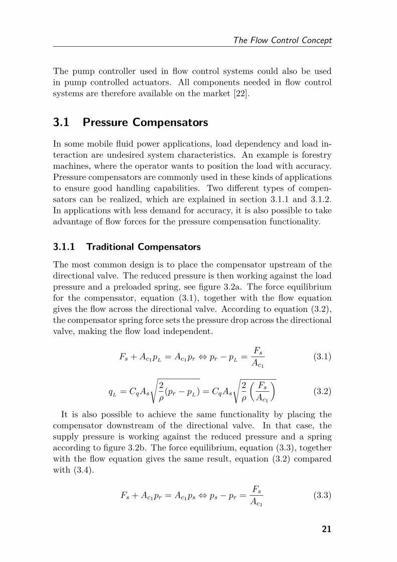
3.1.1 Traditional Compensators
The most common design is to place the compensator upstream of thedirectional valve. The reduced pressure is then working against the loadpressure and a preloaded spring, see figure 3.2a. The force equilibriumfor the compensator, equation (3.1), together with the flow equationgives the flow across the directional valve. According to equation (3.2),the compensator spring force sets the pressure drop across the directionalvalve, making the flow load independent.
Fs + Ac1p
L= Ac1
pr ⇔ pr − pL
=Fs
Ac1
(3.1)
qL
= CqAs
√2
ρ(pr − p
L) = CqAs
√2
ρ
(Fs
Ac1
)(3.2)
It is also possible to achieve the same functionality by placing thecompensator downstream of the directional valve. In that case, thesupply pressure is working against the reduced pressure and a springaccording to figure 3.2b. The force equilibrium, equation (3.3), togetherwith the flow equation gives the same result, equation (3.2) comparedwith (3.4).
Fs + Ac1pr = Ac1
ps ⇔ ps − pr =Fs
Ac1
(3.3)
21

Fluid Power Systems for Mobile Applications
ps pr pL
Ac1
Ac1Fs
As qL
(a) The compensator is placed up-stream of the directional valve.
ps
pr
pL
Ac1
Ac1Fs
As qL
(b) The compensator is placeddownstream of the directionalvalve.
Figure 3.2 Two different ways of realizing a traditional pressure com-
pensator. The pressure drop across the directional valve is set by the
compensator spring force.
qL
= CqAs
√2
ρ(ps − pr) = CqAs
√2
ρ
(Fs
Ac1
)(3.4)
These types of compensators are designed for use with a pressure con-trolled pump. In case of the pump being saturated, the supply pressurewill drop, resulting in the compensator spool at the heaviest load open-ing completely. That function will lose speed and possibly even stop.Functions operated simultaneously at lower pressure levels will, however,move normally.
3.1.2 Flow Sharing Compensators
Another design is to implicate the highest load pressure into the compen-sator. When the pressure is actively controlled, this design is equivalentto the traditional compensator design. However, its characteristics aredifferent when the pump is saturated. All functions will then be giventhe same priority, which means that all functions will decrease in speed.This flow sharing functionality can be achieved by placing a compensatoreither downstream or upstream of the directional valve.
In case of the compensator being located downstream of the direc-tional valve, the reduced pressure is working against the highest loadpressure and a spring, see equation (3.5) and figure 3.3a. The pumppressure margin is defined according to equation (3.6) and the flow canbe calculated according to equation (3.7).
Ac1pr = Ac1
pLmax
+ Fs ⇔ pr = pLmax
+Fs
Ac1
(3.5)
22

The Flow Control Concept
Δpp = ps − pLmax
(3.6)
qL
= CqAs
√2
ρ(ps − pr) = CqAs
√2
ρ
(Δpp − Fs
Ac1
)(3.7)
ps pr pL
Ac1
Ac1Fs
As qL
pLmax
(a) The compensator is placeddownstream of the directionalvalve.
ps
pr pL
Ac1
Ac1
As qL
pLmax
Ac2
Ac2
Fs
(b) The compensator is placed up-stream of the directional valve.
Figure 3.3 Two different ways of realizing a flow sharing pressure com-
pensator. The pressure drop across the directional valve is set by the pump
pressure margin.
The flow sharing pressure compensator placed upstream of the direc-tional valve is similar to its traditional equivalent. Instead of a spring,two pressure signals that constitute the pump pressure margin are act-ing on the compensator, see figure 3.3b. Equation (3.6) together withthe force equilibrium for the compensator, equation (3.8), gives the flowaccording to equation (3.9). The spring in this type of compensator isnot required for the functionality. It can rather be used as a designparameter for, for example, prioritization [23].
Ac2ps + Ac1
pL
= Ac2p
Lmax+ Ac1
pr + Fs ⇔
(pr − pL) =
Ac2
Ac1
(ps − pLmax
) − Fs
Ac1
(3.8)
qL
= CqAs
√2
ρ(pr − p
L) = CqAs
√2
ρ
(Ac2
Ac1
Δpp − Fs
Ac1
)(3.9)
Flow sharing pressure compensators will distribute the entire pumpflow relative to the individual valve openings also when the pump issaturated. A pressure controlled pump which has been saturated cannot
23
Fluid Power Systems for Mobile Applications
control the pressure and can therefore be seen as a flow controlled pump.These compensators are therefore appropriate to use together with a flowcontrolled pump.
3.2 Pump and Valve Control Approaches
In flow control systems, the operator’s joystick signals control the pumpflow and the valve opening simultaneously. For this to work properly,the system software needs knowledge about every flow consumer in thesystem. However, solutions for attaching auxiliary functions withoutknowledge about their flow demand have been presented in [24] and [25].Different control approaches are possible depending on whether tradi-tional compensators or flow sharing compensators are used.
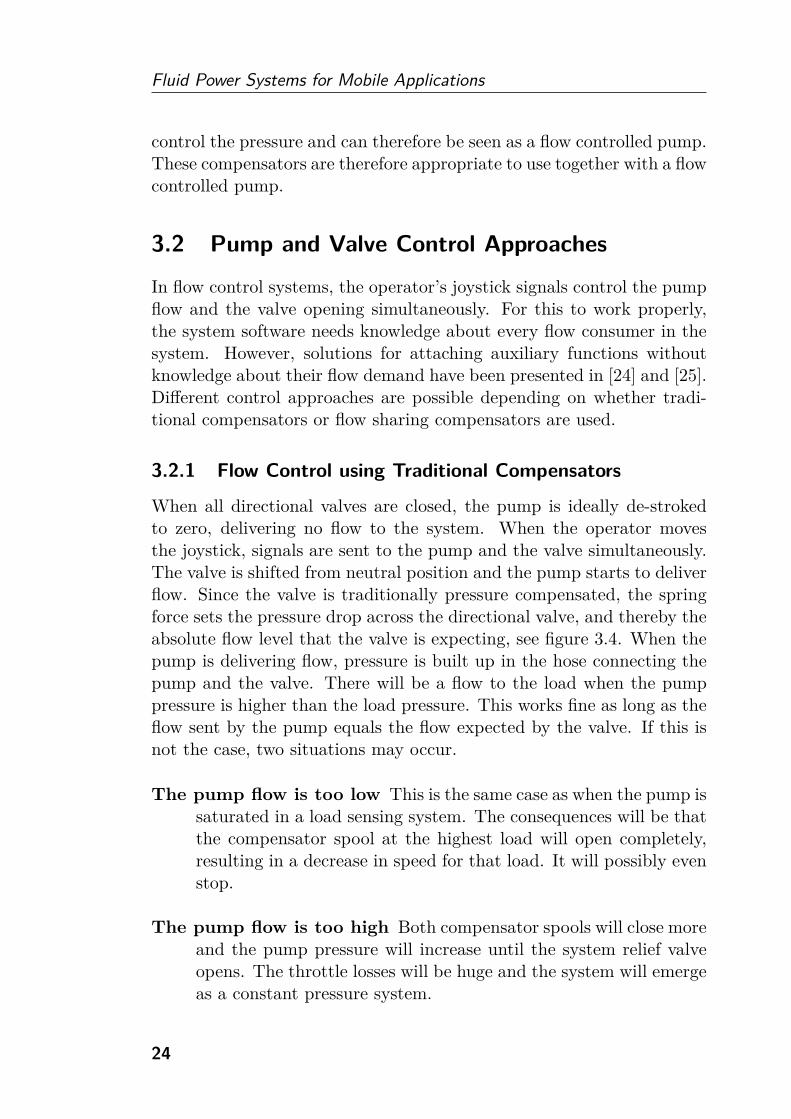
3.2.1 Flow Control using Traditional Compensators
When all directional valves are closed, the pump is ideally de-strokedto zero, delivering no flow to the system. When the operator movesthe joystick, signals are sent to the pump and the valve simultaneously.The valve is shifted from neutral position and the pump starts to deliverflow. Since the valve is traditionally pressure compensated, the springforce sets the pressure drop across the directional valve, and thereby theabsolute flow level that the valve is expecting, see figure 3.4. When thepump is delivering flow, pressure is built up in the hose connecting thepump and the valve. There will be a flow to the load when the pumppressure is higher than the load pressure. This works fine as long as theflow sent by the pump equals the flow expected by the valve. If this isnot the case, two situations may occur.
The pump flow is too low This is the same case as when the pump issaturated in a load sensing system. The consequences will be thatthe compensator spool at the highest load will open completely,resulting in a decrease in speed for that load. It will possibly evenstop.
The pump flow is too high Both compensator spools will close moreand the pump pressure will increase until the system relief valveopens. The throttle losses will be huge and the system will emergeas a constant pressure system.
24

The Flow Control Concept
Figure 3.4 Simplified schematic of a flow control system using tra-
ditional pressure compensators. The system can also be realized with
traditional compensators placed downstream of the directional valves.
The reason for this is that traditional pressure compensators controlthe absolute flow across the directional valve by reducing the pumppressure relative to the load pressure of its own load. This works fineas long as the pump pressure is actively controlled, with for instance aload pressure feedback. Otherwise, the flow situation in the system isover-determined.
A lot of research solving this flow matching problem has been pre-sented. Djurovic and Helduser [26] introduce a position sensor placedon the directional valve. It allows precise knowledge of the flow expectedby the valve. It is also possible to equip the compensator with a positionsensor [27]. If no compensator is close to fully opened, the pump flow istoo high. In case of the pump flow being too low, the compensator atthe highest load would be completely opened. A bleed-off valve to tankis proposed by several authors [24] [26] [27]. A small overflow is then ac-ceptable, which could be used in closed loop control if a position sensoris added. Fedde and Harms [28] discuss the pros and cons with overflow
25
Fluid Power Systems for Mobile Applications
and underflow when using a bleed-off valve. Grösbrink et al. [29] [30]propose a system design where the pump is pressure controlled for lowpump flows and flow controlled for high flow rates. It is also possible toshift from flow control to pressure control in case of an undesirable press-ure build up [31]. A review of solutions to the flow matching problem inflow control systems using traditional compensators has been made byDjurovic in [32].
3.2.2 Flow Control using Flow Sharing Compensators
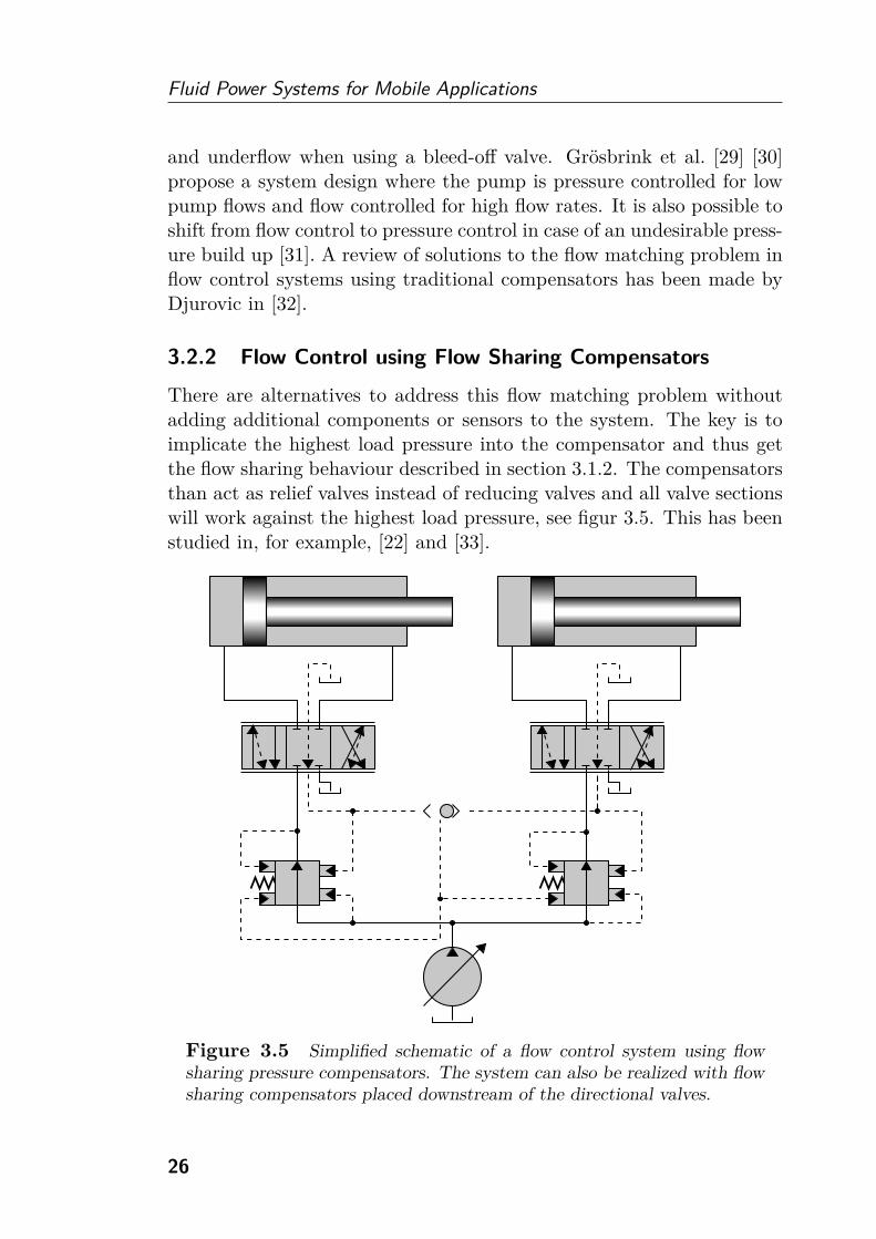
There are alternatives to address this flow matching problem withoutadding additional components or sensors to the system. The key is toimplicate the highest load pressure into the compensator and thus getthe flow sharing behaviour described in section 3.1.2. The compensatorsthan act as relief valves instead of reducing valves and all valve sectionswill work against the highest load pressure, see figur 3.5. This has beenstudied in, for example, [22] and [33].
Figure 3.5 Simplified schematic of a flow control system using flow
sharing pressure compensators. The system can also be realized with flow
sharing compensators placed downstream of the directional valves.
26
The Flow Control Concept
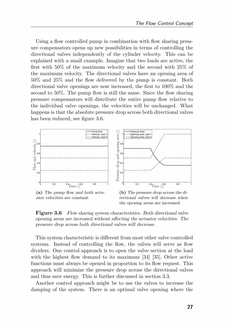
Using a flow controlled pump in combination with flow sharing press-ure compensators opens up new possibilities in terms of controlling thedirectional valves independently of the cylinder velocity. This can beexplained with a small example. Imagine that two loads are active, thefirst with 50% of the maximum velocity and the second with 25% ofthe maximum velocity. The directional valves have an opening area of50% and 25% and the flow delivered by the pump is constant. Bothdirectional valve openings are now increased, the first to 100% and thesecond to 50%. The pump flow is still the same. Since the flow sharingpressure compensators will distribute the entire pump flow relative tothe individual valve openings, the velocities will be unchanged. Whathappens is that the absolute pressure drop across both directional valveshas been reduced, see figure 3.6.
0 0.2 0.4 0.6 0.8 10
0.2
0.4
0.6
0.8
1
Pump flowVelocity, load 1Velocity, load 2
Flo
wan
dve
loci
ty[-]
Time [-]
(a) The pump flow and both actu-ator velocities are constant.
0 0.2 0.4 0.6 0.8 10
0.2
0.4
0.6
0.8
1
Pressure dropOpening area, load 1Opening area, load 2
Time [-]
Pre
ssure
dro
pan
dop
enin
gar
ea[-]
(b) The pressure drop across the di-rectional valves will decrease whenthe opening areas are increased.
Figure 3.6 Flow sharing system characteristics. Both directional valve
opening areas are increased without affecting the actuator velocities. The
pressure drop across both directional valves will decrease.
This system characteristic is different from most other valve controlledsystems. Instead of controlling the flow, the valves will serve as flowdividers. One control approach is to open the valve section at the loadwith the highest flow demand to its maximum [34] [35]. Other activefunctions must always be opened in proportion to its flow request. Thisapproach will minimize the pressure drop across the directional valvesand thus save energy. This is further discussed in section 3.3.
Another control approach might be to use the valves to increase thedamping of the system. There is an optimal valve opening where the
27

Fluid Power Systems for Mobile Applications
damping is maximized. For example, when a function is oscillating thevalve opening could be reduced temporarily in order to dampen theoscillations. When no oscillations are present, a more energy efficientcontrol approach can be used. This is further discussed in section 4.3.1.
3.3 Energy Efficiency
The energy efficiency of flow control systems is similar to load sensingsystems. The pump pressure is adjusted according to the highest loadand high losses might occur when loads with different pressure demandsare operated simultaneously. However, instead of a prescribed pressuremargin, as in load sensing systems, the pressure drop between pump andload is given by the resistance in the hoses and in the valves. Further-more, it is also possible to lower the pressure drop across the directionalvalve by means of a more energy efficient control strategy.
In load sensing systems, the pump pressure margin is set to overcomethe losses in the pump hose, the compensator and the directional valve.These losses are system dependent and will change with internal andexternal conditions such as temperature, oil properties, hose length, etc.The pressure margin is set according to the worst case to ensure it ishigh enough at all operating points.
The pressure drop between pump and load can be divided into threedifferent losses:
Losses between pump and valve There will be a pressure drop be-tween the pump and the valve. The magnitude will depend onthe internal and external properties mentioned above, but mostimportantly the flow rate. A simplified model is that the lossesincrease with the square of the flow rate.
Losses across the compensator There will be a pressure drop acrossthe compensator. High losses occur if the supply pressure is muchhigher than the load pressure. This is the case at partial loadingconditions. The smallest possible loss occurs when the compen-sator is fully opened. In that case, the required pressure dropincreases with the square of the flow rate.
Losses across the directional valve Typically, the compensatormakes sure that the pressure drop across the directional valveis constant. However, the smallest possible pressure drop occurs
28
The Flow Control Concept
if the valve is fully open. The pressure drop will then follow theflow equation, similar to the compensator pressure drop.
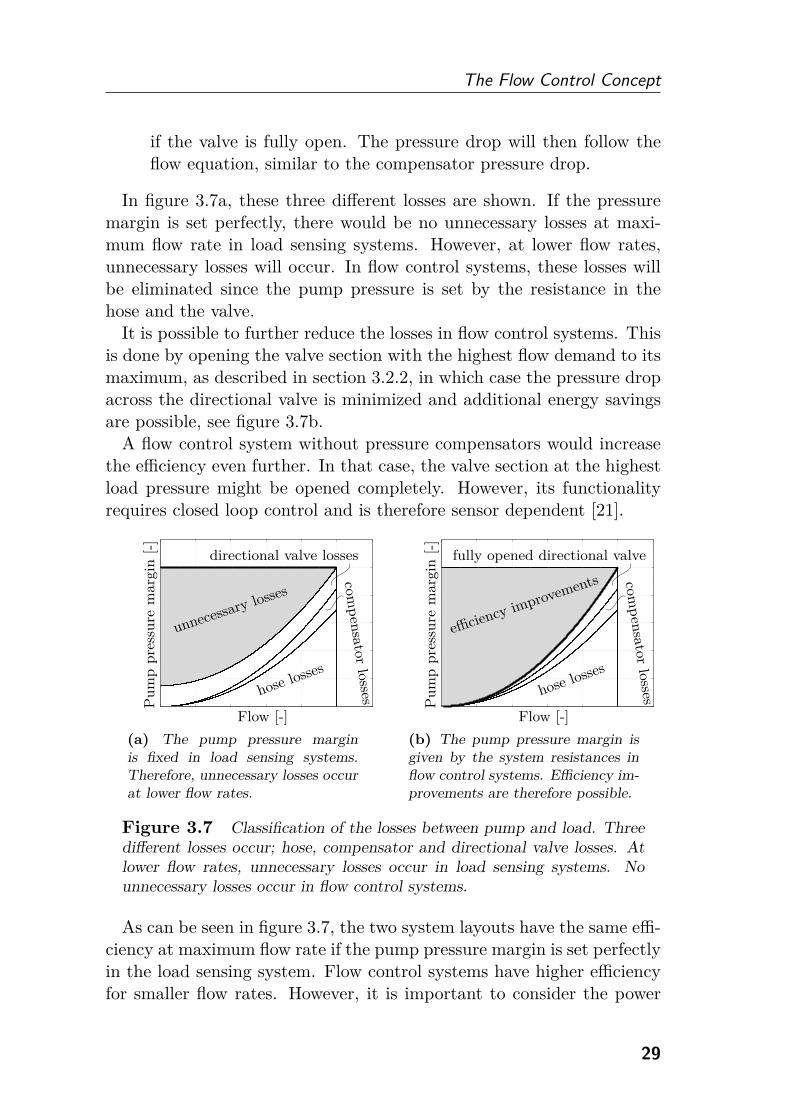
In figure 3.7a, these three different losses are shown. If the pressuremargin is set perfectly, there would be no unnecessary losses at maxi-mum flow rate in load sensing systems. However, at lower flow rates,unnecessary losses will occur. In flow control systems, these losses willbe eliminated since the pump pressure is set by the resistance in thehose and the valve.
It is possible to further reduce the losses in flow control systems. Thisis done by opening the valve section with the highest flow demand to itsmaximum, as described in section 3.2.2, in which case the pressure dropacross the directional valve is minimized and additional energy savingsare possible, see figure 3.7b.
A flow control system without pressure compensators would increasethe efficiency even further. In that case, the valve section at the highestload pressure might be opened completely. However, its functionalityrequires closed loop control and is therefore sensor dependent [21].
Pu
mp
pre
ssu
rem
arg
in[-
]
Flow [-]
unnecessary losses
directional valve losses
hose losses
com
pen
sato
rlo
sses
(a) The pump pressure marginis fixed in load sensing systems.Therefore, unnecessary losses occurat lower flow rates.
Pu
mp
pre
ssu
rem
arg
in[-
]
Flow [-]
efficiency improvements
fully opened directional valve
hose losses
com
pen
sato
rlo
sses
(b) The pump pressure margin isgiven by the system resistances inflow control systems. Efficiency im-provements are therefore possible.
Figure 3.7 Classification of the losses between pump and load. Three
different losses occur; hose, compensator and directional valve losses. At
lower flow rates, unnecessary losses occur in load sensing systems. No
unnecessary losses occur in flow control systems.
As can be seen in figure 3.7, the two system layouts have the same effi-ciency at maximum flow rate if the pump pressure margin is set perfectlyin the load sensing system. Flow control systems have higher efficiencyfor smaller flow rates. However, it is important to consider the power
29

Fluid Power Systems for Mobile Applications
losses rather than the pressure losses. For low flow rates, the power losswill be small even for high pressure drops. Figure 3.8 shows the powersaving opportunities for flow control systems. The largest power savingsoccur in the medium flow rate area. If the directional valve is openedcompletely, even more power can be saved.
Pow
er[-
]
Flow [-]
fully openeddirectional valve
power savings
Figure 3.8 Power savings in flow control systems compared to load
sensing systems. More power can be saved if the directional valve is com-
pletely opened. No power is saved at maximum flow rate.
Flow control systems have no unnecessary losses for the highest load.All losses that occur are necessary and limited by, for example, the diam-eter of the hoses and the maximum opening areas in the valve. However,flow control systems still have high losses at partial loading conditions.To increase efficiency even further, individual metering valves or addi-tional hydraulic machines are required.
A flow control system with two hydraulic pumps has been studiedin [36] and [37]. The aim is to reduce the losses at partial loadingconditions without increasing the total installed displacement. This isachieved by connecting the two pumps when high flow rates are requiredby one load. Connecting several pumps at high flow rates is a commonsolution for more simple systems, for example, in excavators.
30
4Dynamic Analysis
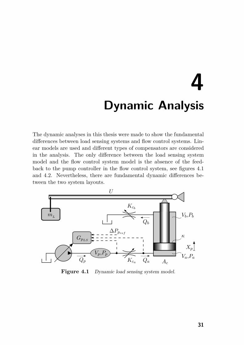
The dynamic analyses in this thesis were made to show the fundamentaldifferences between load sensing systems and flow control systems. Lin-ear models are used and different types of compensators are consideredin the analysis. The only difference between the load sensing systemmodel and the flow control system model is the absence of the feed-back to the pump controller in the flow control system, see figures 4.1and 4.2. Nevertheless, there are fundamental dynamic differences be-tween the two system layouts.
Qa Ac
Va,Pa
Vb,Pb
κ
Qb
mL
U
Kcb
Qp
Vp,Pp
GpLS
Kca
ΔPpref
Xp
Figure 4.1 Dynamic load sensing system model.
31

Fluid Power Systems for Mobile Applications
Qa Ac
Va,Pa
Vb,Pb
κ
Qb
mL
U
Kcb
Qp
Vp,Pp
GpF C
Kca
Qpref
Xp
Figure 4.2 Dynamic flow control system model.
4.1 Mathematical Model
A linear mathematical model is constructed to perform the dynamicanalyses. The derivation of the equations is shown in [38].
The pump controller can be described in two different ways. In loadsensing systems, the controller consists of a pressure controlled valvethat controls the displacement piston. If the pressure balance, ΔPp =Pp −Pa, is disturbed, the valve is displaced and the pump setting is thenproportional to the integrated valve flow. Here, the pump is modelledas a pure inductance, see equation (4.1).
GpLS=
Qp
ΔPpref− ΔPp
=1
Lps(4.1)
The pump controller in flow control systems controls the displacement,and thereby the flow, directly instead of maintaining a certain pressuremargin above the highest load pressure. Such a pump controller has noexternal feedback from the system, similar to the load sensing feedback.Here, the transfer function describing the displacement controlled pumpdynamics is called GpF C
, see equation (4.2).
GpF C=
Qp
Qpref
(4.2)
The continuity equation of the pump volume yields the transfer func-tion in equation (4.3).
Hs =Pp
Qp − Qa=
βe
Vps(4.3)
32

Dynamic Analysis
The model for the inlet orifice in the directional valve will be differentdepending on the compensator design. A non-compensated valve willhave a flow-pressure dependency according to equation (4.4). In thisanalysis, the valve is considered to be much faster than the rest of thesystem. The valve dynamics is therefore ignored. The dynamics ofpressure compensated valves have been studied in, for example, [39]and [40].
Gva =Qa
Pp − Pa= Kca (4.4)
A traditionally compensated valve will have no flow-pressure depen-dency since the pressure drop across the directional valve is constant,see equation (4.5).
Gva =Qa
Pp − Pa= 0 (4.5)
A flow sharing pressure compensated valve will have a flow-pressuredependency, similar to a non-compensated valve, for the highest load.Lighter loads have no flow-pressure dependency, like traditional com-pensated valves. However, lighter loads will be disturbed by the highestload due to cross-coupling of the highest load pressure to all compen-sators [41].
Gva =Qa
Pp − Pa= Kca , ∀Pa = Pamax
Gva =Qa
Pp − Pa= 0, ∀Pa < Pamax (4.6)
Gvea =Qa
Pp − Pamax
= Kca , ∀Pa < Pamax
A detailed investigation of valve models using different compensationtechniques can be found in [41] and paper [II].
A mass load with a gear ratio is considered to act on a cylinder. Thecontinuity equation for the cylinder chambers together with the forceequilibrium for the piston is shown in equations (4.7), (4.8) and (4.9).
Qa =Va
βesPa + AcsXp (4.7)
U2mLs2Xp + BpsXp = AcPa − κAcPb (4.8)
κAcsXp − Qb =Vb
βesPb (4.9)
33

Fluid Power Systems for Mobile Applications
It is also possible to describe a load which consists of a hydraulic motorby similar equations [II].
The outlet orifice in the directional valve is considered to have a flow-pressure dependency according to equation (4.10).
Gvb=
Qb
Pb= Kcb
(4.10)
4.2 Pump Stability
Due to the absence of the load pressure feedback to the pump con-troller in flow control systems, there is a fundamental dynamic differ-ence between load sensing and flow control systems. To show this, themathematical model in section 4.1 can be simplified. A flow-pressuredependency at the inlet side of the valve is assumed and the outlet ori-fice is ignored. The simplifications will not influence the fundamentaldifferences but is important to bear in mind when making other dynamicanalyses.
A transfer function from inlet flow to pressure in the cylinder canbe derived using equations (4.7) and (4.8). Ignoring the outlet orificeresults in a constant pressure on the piston rod side.
ZL
=Pa
Qa=
U2mLs + Bp
Va
βeU2m
Ls2 + Va
βeBps + A2
c
(4.11)
4.2.1 Load Sensing Systems
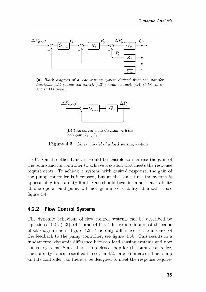
The dynamic behaviour of load sensing systems can be described byequations (4.1), (4.3), (4.4) and (4.11). By reducing the block diagramin figure 4.3a, the open loop transfer function from desired pump press-ure margin, ΔPpref
, to actual pressure difference, ΔPp = Pp − Pa, canbe derived according to equation (4.12). A complete investigation ofload sensing systems and their dynamic properties, including pump con-trollers, can be found in [42].
GpLSGo = GpLS
Hs
1 + Gva (ZL
+ Hs)(4.12)
By closing the control loop, the pump controller, GpLS, is a part of the
loop gain, GpLSGo, as shown in figure 4.3b. To achieve a stable system
the loop gain must be kept lower than unity when the phase crosses
34
Dynamic Analysis
+
−
GpLS
+
−
Hs+
−
Gva
ZL
1Gva
�
�
�
ΔPp,ref Qp Pp ΔPp Qa
Pa
(a) Block diagram of a load sensing system derived from the transferfunctions (4.1) (pump controller), (4.3) (pump volume), (4.4) (inlet valve)and (4.11) (load).
+
−
GpLS Go�
ΔPp,ref ΔPp
(b) Rearranged block diagram with theloop gain GpLS
Go.
Figure 4.3 Linear model of a load sensing system.
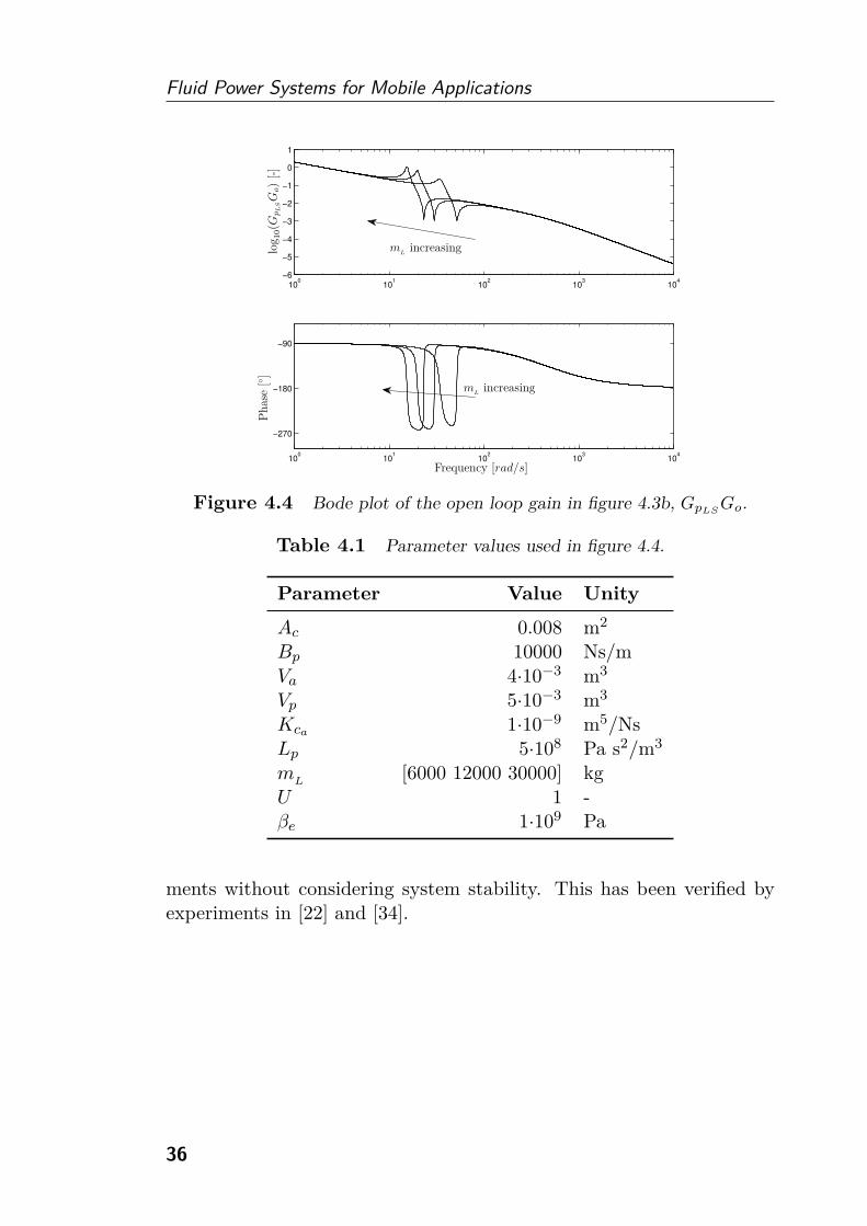
-180◦. On the other hand, it would be feasible to increase the gain ofthe pump and its controller to achieve a system that meets the responserequirements. To achieve a system, with desired response, the gain ofthe pump controller is increased, but at the same time the system isapproaching its stability limit. One should bear in mind that stabilityat one operational point will not guarantee stability at another, seefigure 4.4.
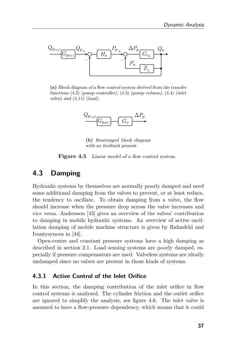
4.2.2 Flow Control Systems
The dynamic behaviour of flow control systems can be described byequations (4.2), (4.3), (4.4) and (4.11). This results in almost the sameblock diagram as in figure 4.3. The only difference is the absence ofthe feedback to the pump controller, see figure 4.5b. This results in afundamental dynamic difference between load sensing systems and flowcontrol systems. Since there is no closed loop for the pump controller,the stability issues described in section 4.2.1 are eliminated. The pumpand its controller can thereby be designed to meet the response require-
35
Fluid Power Systems for Mobile Applications
100
101
102
103
104
−6
−5
−4
−3
−2
−1
0
1
100
101
102
103
104
−270
−180
−90
log
10(G
pL
SG
o)
[-]
Phas
e[◦ ]
Frequency [rad/s]
mL
increasing
mL
increasing
Figure 4.4 Bode plot of the open loop gain in figure 4.3b, GpLSGo.
Table 4.1 Parameter values used in figure 4.4.
Parameter Value Unity
Ac 0.008 m2
Bp 10000 Ns/mVa 4·10−3 m3
Vp 5·10−3 m3
Kca 1·10−9 m5/NsLp 5·108 Pa s2/m3
mL
[6000 12000 30000] kgU 1 -βe 1·109 Pa
ments without considering system stability. This has been verified byexperiments in [22] and [34].
36
Dynamic Analysis
GpF C
+
−
Hs+
−
Gva
ZL
�
�
Qpref Qp Pp ΔPp Qa
Pa
(a) Block diagram of a flow control system derived from the transferfunctions (4.2) (pump controller), (4.3) (pump volume), (4.4) (inletvalve) and (4.11) (load).
GpF C Go
Qpref ΔPp
(b) Rearranged block diagramwith no feedback present.
Figure 4.5 Linear model of a flow control system.
4.3 Damping
Hydraulic systems by themselves are normally poorly damped and needsome additional damping from the valves to prevent, or at least reduce,the tendency to oscillate. To obtain damping from a valve, the flowshould increase when the pressure drop across the valve increases andvice versa. Andersson [43] gives an overview of the valves’ contributionto damping in mobile hydraulic systems. An overview of active oscil-lation damping of mobile machine structure is given by Rahmfeld andIvantysynova in [44].
Open-centre and constant pressure systems have a high damping asdescribed in section 2.1. Load sensing systems are poorly damped, es-pecially if pressure compensators are used. Valveless systems are ideallyundamped since no valves are present in those kinds of systems.
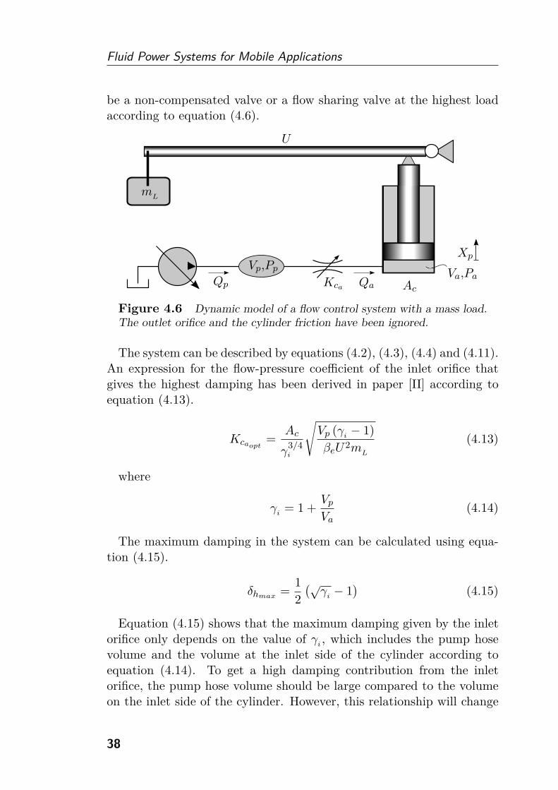
4.3.1 Active Control of the Inlet Orifice
In this section, the damping contribution of the inlet orifice in flowcontrol systems is analysed. The cylinder friction and the outlet orificeare ignored to simplify the analysis, see figure 4.6. The inlet valve isassumed to have a flow-pressure dependency, which means that it could
37
Fluid Power Systems for Mobile Applications
be a non-compensated valve or a flow sharing valve at the highest loadaccording to equation (4.6).
Qa Ac
Va,Pa
mL
U
Qp
Vp,Pp
Kca
Xp
Figure 4.6 Dynamic model of a flow control system with a mass load.
The outlet orifice and the cylinder friction have been ignored.
The system can be described by equations (4.2), (4.3), (4.4) and (4.11).An expression for the flow-pressure coefficient of the inlet orifice thatgives the highest damping has been derived in paper [II] according toequation (4.13).
Kcaopt=
Ac
γ3/4i
√Vp (γ
i− 1)
βeU2mL
(4.13)
where
γi
= 1 +Vp
Va(4.14)
The maximum damping in the system can be calculated using equa-tion (4.15).
δhmax=
1
2
(√γ
i− 1
)(4.15)
Equation (4.15) shows that the maximum damping given by the inletorifice only depends on the value of γ
i, which includes the pump hose
volume and the volume at the inlet side of the cylinder according toequation (4.14). To get a high damping contribution from the inletorifice, the pump hose volume should be large compared to the volumeon the inlet side of the cylinder. However, this relationship will change
38

Dynamic Analysis
0
0.1
0.2
0.3
0.4
0.5
0.6
0.7
0.8
Dam
pin
g[-
]
Increased opening area
γi
increasing
�
Figure 4.7 System damping as a function of the opening area of the
inlet orifice. A small value of γi
gives a low damping regardless of the
opening area. The damping will increase with higher values of γi.
during the cylinder stroke. The damping as a function of the inlet orificeopening area for different values of γ
iis shown in figure 4.7.
To get the highest possible damping for a given value of γi, the inlet
orifice opening area has to be small. During certain points of opera-tion this might result in substantial power losses [II]. To avoid this itis possible to use the more energy efficient control strategy describedin section 3.2.2 while no oscillations are present. When damping is re-quired, the valve can temporarily be closed more to reach the peaks infigure 4.7. Finally, when the oscillations have died out, the energy effi-cient control strategy can be applied again. This is possible to do in flowcontrol systems without affecting the cylinder velocities if flow sharingpressure compensators are used.
Theoretically, a flow control system using traditional compensatorsobtains no damping from the inlet orifice since the flow is independentof pressure changes, see equation (4.5). This is also true for lower loadsusing flow sharing compensators according to equation (4.6). One wayto obtain damping for such loads is to implement active damping, usingfor example a dynamic load pressure feedback.
A special case of this analysis is when the inlet orifice opening areaapproaches infinity. This is the case in valveless systems, which have no
39

Fluid Power Systems for Mobile Applications
orifices at all. As can be seen in figure 4.7, the damping then approacheszero. Consequently, a valveless system is ideally undamped.
4.3.2 Design and Control of the Outlet Orifice
In this section, the damping contribution of the outlet orifice is analysed.This analysis is not limited to flow control systems, but is valid for allpump controller designs. The prerequisite is that the inlet flow can bemodelled as a perfect flow source, which is true if the inlet orifice has noflow-pressure dependency, see figure 4.8. This can be realized with, forexample, a traditional pressure compensator.
Pa
Qa
Ac
Va
Vb
κ
Qb
Pbm
L
U
Kcb
Figure 4.8 Dynamic model of a flow controlled cylinder with a mass
load and an outlet orifice. The pump controller can be of any design; it
does not affect the analysis.
The system can be described by equations (4.7)-(4.10). Similar to theanalysis in section 4.3.1, the viscous friction in the cylinder has beenignored to simplify the analysis. An expression for the flow-pressurecoefficient of the outlet orifice that gives the highest damping has beenderived in paper [III] according to equation (4.16).
Kcbopt= κAc
√Vb
βeU2mL
(γo − 1)γ3/4
o(4.16)
where
γo = 1 + κ2 Va
Vb(4.17)
40
Dynamic Analysis
The maximum damping in the system can be calculated using equa-tion (4.18).
δhmax=
1
2
(√γo − 1
)(4.18)
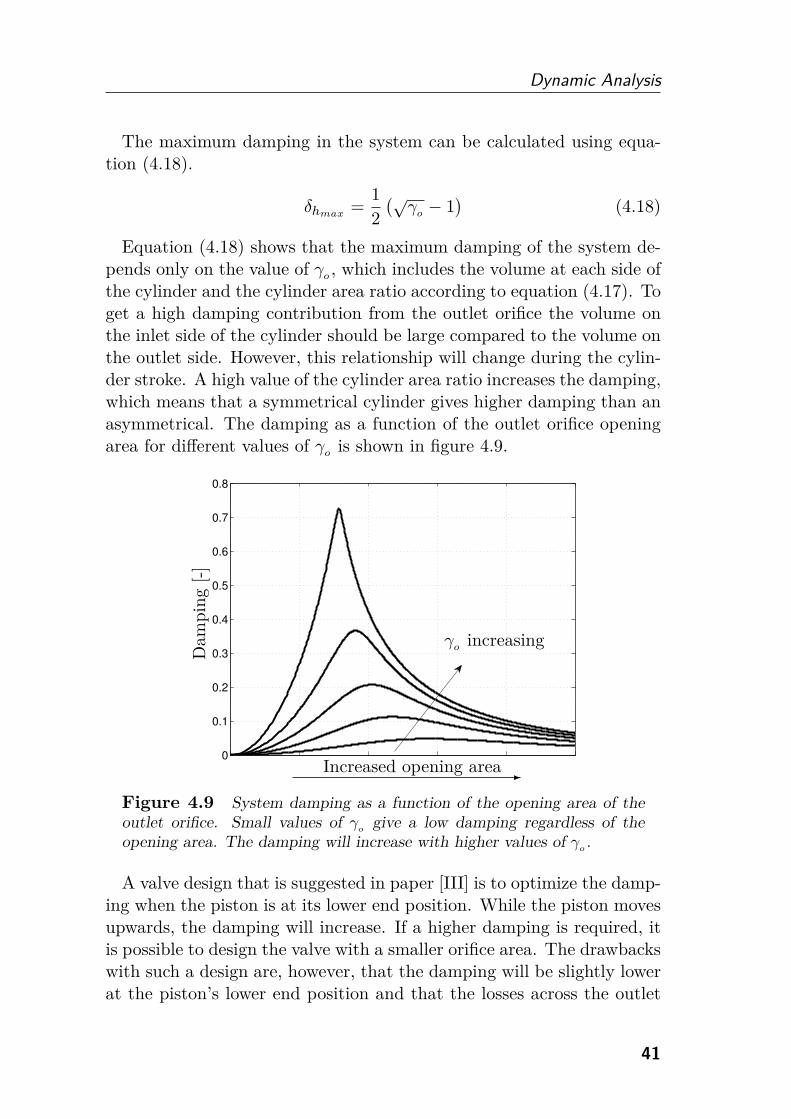
Equation (4.18) shows that the maximum damping of the system de-pends only on the value of γo , which includes the volume at each side ofthe cylinder and the cylinder area ratio according to equation (4.17). Toget a high damping contribution from the outlet orifice the volume onthe inlet side of the cylinder should be large compared to the volume onthe outlet side. However, this relationship will change during the cylin-der stroke. A high value of the cylinder area ratio increases the damping,which means that a symmetrical cylinder gives higher damping than anasymmetrical. The damping as a function of the outlet orifice openingarea for different values of γo is shown in figure 4.9.
0
0.1
0.2
0.3
0.4
0.5
0.6
0.7
0.8
Dam
pin
g[-
]
Increased opening area
γo increasing
�
Figure 4.9 System damping as a function of the opening area of the
outlet orifice. Small values of γo
give a low damping regardless of the
opening area. The damping will increase with higher values of γo.
A valve design that is suggested in paper [III] is to optimize the damp-ing when the piston is at its lower end position. While the piston movesupwards, the damping will increase. If a higher damping is required, itis possible to design the valve with a smaller orifice area. The drawbackswith such a design are, however, that the damping will be slightly lowerat the piston’s lower end position and that the losses across the outlet
41
Fluid Power Systems for Mobile Applications
orifice will be higher. If lower losses are required it is possible to designthe valve with a larger opening area. However, this is at the expense ofa lower damping. There is no point in designing the valve with a toosmall orifice area. The damping will then be low and the losses high.
In case of the inlet and outlet orifices being decoupled, as in indi-vidual metering systems, it would be possible to optimize the dampingduring the cylinder stroke. While the piston is moving, the outlet orificecould be controlled in order to achieve the highest possible damping. Itwould also be possible to use a similar control approach as described insection 4.3.1. When no oscillations are present, the outlet orifice couldbe fully opened, minimizing the losses. When damping is required, thecontroller could shift to optimize the damping and temporarily allowhigher losses.
42
5Experimental
Results
The energy efficiency improvements described in section 3.3 have beenvalidated using a wheel loader application. Also, the theories concerningthe design and control of the outlet orifice described in section 4.3.2 havebeen validated in a test rig.
5.1 Energy Efficiency Improvements
5.1.1 Hardware Requirements
The hardware requirements in flow control systems are similar to loadsensing systems. To achieve the same system capacity, a pump size ofthe same magnitude is used. Only the pump controller needs to be dif-ferent. Instead of actively maintaining a certain pressure margin abovethe highest load pressure, the pump displacement is controlled directlyfrom the operator’s demand signals. This requires an electrically con-trolled displacement controller for the pump. However, the load sensinghose to the pump controller can be removed.
Flow control systems use the same type of valves as load sensing sys-tems. Flow sharing pressure compensators are favourable but work-arounds with traditional compensators also exist, see section 3.2.1. Insome valve designs, a traditional compensator placed upstream of thedirectional valve can be replaced with its flow sharing equivalent withouteven replacing the valve housing [23].
Sensors are not required to achieve the desired functionality in flow
43

Fluid Power Systems for Mobile Applications
control systems if pressure compensators are used. However, it wouldbe beneficial to use sensors to detect if the cylinder end stops have beenreached. In that case, the valve could be closed and the pump flowadjusted to avoid unnecessary energy losses.
5.1.2 A Demonstrator System
To verify the energy efficiency improvements in the flow control concept,measurements where performed on a wheel loader application, see fig-ure 5.1. The machine was equipped with a pump that can be operatedin both pressure and flow control modes and a valve prepared for usewith both traditional and flow sharing compensators, placed upstreamof the directional valve.
Figure 5.1 The machine used for experiments.
In figure 5.2c, the pump pressure margin for both the load sensing andthe flow control systems can be seen. The measurements agree with thetheoretical pressure margin shown in figure 3.7. The flow sent by thepump is similar in both systems, see figure 5.2a. It can also be observedin figure 5.2b that the pressure is more oscillative in the load sensingsystem. This is because the pump controller operates in a closed loopcontrol mode [42].
A short loading cycle has also been performed to compare load sensingand flow control. Only the working hydraulics have been taken into con-sideration, neither the steering nor the transmission. Figure 5.3a showsthe position of the actuators and figure 5.3b the energy consumption.The energy consumption was reduced by 14% for the flow control systemfor this particular application. This is the same order of magnitude asexperiments performed in [24] and [34].
44

Experimental Results
0 1 2 3 4 5 60
50
100
150
Flo
w[l
/min
]
Time [s]
(a) Measured flow for both systems.The flow is increased from zero tomaximum.
0 1 2 3 4 5 60
5
10
15
20
25
30
35
40
45
50
Time [s]
Pre
ssure
[bar]
(b) Measured pump pressure mar-gin for both systems while the flowis increased.
0 20 40 60 80 1000
5
10
15
20
25
30
Flow [l/min]
Pre
ssure
[bar]
Load sensing
Flowcon
trol
(c) Measured pump pressure mar-gin as a function of measured flow.Load sensing systems have a con-stant margin while flow control sys-tems have a margin given by the sys-tem resistances.
Figure 5.2 Experimental results showing the potential of reducing the
pump pressure margin in flow control systems compared to load sensing
systems.
45

Fluid Power Systems for Mobile Applications
0 5 10 15 20 25 30 350
0.1
0.2
0.3
0.4
0.5
0.6
0.7
Pos
itio
n[m
]
Time [s]
Lift
Tilt
(a) Measured positions of the actu-ators during the cycle.
0 5 10 15 20 25 30 350
20
40
60
80
100
120
140
160
Time [s]
Ener
gy[k
J]
Load sensing
Flow control
(b) Measured energy consumptionduring the cycle.
Figure 5.3 Experimental results showing the actuator positions and
the consumed energy in a short loading cycle. The flow control system
consumed 14% less energy during the cycle compared to the load sensing
system.
46
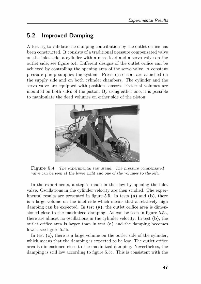
Experimental Results
5.2 Improved Damping
A test rig to validate the damping contribution by the outlet orifice hasbeen constructed. It consists of a traditional pressure compensated valveon the inlet side, a cylinder with a mass load and a servo valve on theoutlet side, see figure 5.4. Different designs of the outlet orifice can beachieved by controlling the opening area of the servo valve. A constantpressure pump supplies the system. Pressure sensors are attached onthe supply side and on both cylinder chambers. The cylinder and theservo valve are equipped with position sensors. External volumes aremounted on both sides of the piston. By using either one, it is possibleto manipulate the dead volumes on either side of the piston.
Figure 5.4 The experimental test stand. The pressure compensated
valve can be seen at the lower right and one of the volumes to the left.
In the experiments, a step is made in the flow by opening the inletvalve. Oscillations in the cylinder velocity are then studied. The exper-imental results are presented in figure 5.5. In tests (a) and (b), thereis a large volume on the inlet side which means that a relatively highdamping can be expected. In test (a), the outlet orifice area is dimen-sioned close to the maximized damping. As can be seen in figure 5.5a,there are almost no oscillations in the cylinder velocity. In test (b), theoutlet orifice area is larger than in test (a) and the damping becomeslower, see figure 5.5b.
In test (c), there is a large volume on the outlet side of the cylinder,which means that the damping is expected to be low. The outlet orificearea is dimensioned close to the maximized damping. Nevertheless, thedamping is still low according to figure 5.5c. This is consistent with the
47
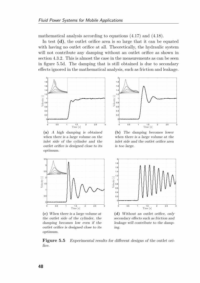
Fluid Power Systems for Mobile Applications
mathematical analysis according to equations (4.17) and (4.18).In test (d), the outlet orifice area is so large that it can be equated
with having no outlet orifice at all. Theoretically, the hydraulic systemwill not contribute any damping without an outlet orifice as shown insection 4.3.2. This is almost the case in the measurements as can be seenin figure 5.5d. The damping that is still obtained is due to secondaryeffects ignored in the mathematical analysis, such as friction and leakage.
0 0.5 1 1.5 2 2.5 3
0
0.2
0.4
0.6
0.8
1
1.2
1.4
1.6
1.8
2
Vel
ocit
y[-]
Time [s]
(a) A high damping is obtainedwhen there is a large volume on theinlet side of the cylinder and theoutlet orifice is designed close to itsoptimum.
0 0.5 1 1.5 2 2.5 3
0
0.2
0.4
0.6
0.8
1
1.2
1.4
1.6
1.8
2
Vel
ocit
y[-]
Time [s]
(b) The damping becomes lowerwhen there is a large volume at theinlet side and the outlet orifice areais too large.
0 0.5 1 1.5 2 2.5 3
0
0.5
1
1.5
2
2.5
3
3.5
Vel
ocit
y[-]
Time [s]
(c) When there is a large volume atthe outlet side of the cylinder, thedamping becomes low even if theoutlet orifice is designed close to itsoptimum.
0 0.5 1 1.5 2 2.5 3
0
0.2
0.4
0.6
0.8
1
1.2
1.4
1.6
1.8
2
Vel
ocit
y[-]
Time [s]
(d) Without an outlet orifice, onlysecondary effects such as friction andleakage will contribute to the damp-ing.
Figure 5.5 Experimental results for different designs of the outlet ori-
fice.
48
6Summary and
Conclusions
This thesis studies a system design where the pump displacement set-ting is controlled based on the operator’s command signals rather thanmaintaining a certain pressure margin above the highest load pressure.Conventional load sensing systems are state-of-the-art in industry todayand are therefore used as comparison base.
The fundamental difference between flow control and load sensing isthat the load pressure feedback hose to the pump controller can beremoved. Instead of controlling the pump in a closed loop control mode,an open control mode can be used with no feedbacks present. Thismakes the system design process simpler since the pump can be designedto meet the response requirements without considering system stability.As long as the pump is stable as an isolated component, it will not causeany stability issues in the complete system. In load sensing systems onthe other hand, an apparently stable pump can cause instability in thecomplete system.
Flow control systems are more energy efficient compared to load sens-ing systems. This is because the pressure difference between pump andload is given by the system resistance rather than a prescribed pumppressure margin. The two system layouts have the same efficiency whenthe pump is saturated. However, in all other operational points, flowcontrol systems have a higher efficiency than load sensing systems. Thereare also potential energy savings tied to the absence of active control ofthe pump.
Pressure compensators are key components in flow control systems.
49
Fluid Power Systems for Mobile Applications
Traditional compensators control the absolute flow through the direc-tional valves. If the pump also controls the flow, the flow situation inthe system is over-determined and flow matching problems occur. Thiscan be solved by introducing sensors or a bleed-off valve. Another solu-tion is to use flow sharing pressure compensators. Instead of controllingthe flow, the valves will then serve as flow dividers, eliminating the flowmatching problem. Both traditional and flow sharing compensators canbe realized by placing the compensators either upstream or downstreamof the directional valves. A drawback with flow sharing compensators isthat the highest load dynamically will disturb all lighter loads.
Damping is a desired property in fluid power systems. Low dampingmakes the system oscillative, which has a negative impact on both theproductivity and the operator. Two different ways to obtain dampingin flow control systems are analysed in this thesis, either by the inletorifice or by the outlet orifice in the directional valve. If flow sharingcompensators are used, it is possible to control the inlet orifice, with-out affecting the actuator velocity, with the objective to optimize thedamping. Active damping measures are required to obtain damping bythe inlet orifice if traditional compensators are used. Some design rulesto obtain a high damping by the outlet orifice are proposed. From anenergy efficiency point of view, it is often better to obtain damping bythe outlet orifice since a smaller pressure drop is required.
It is possible to combine flow control with other working hydraulicsystems. For example, flow control could be used as a complement topump controlled actuators. Some high power consumers could have onededicated pump while other, low power, consumers share one commonpump. In that case, the total installed displacement could be kept ata reasonable level while all pumps could be displacement controlled.Another possibility could be to use an electric motor in combinationwith a fixed displacement pump, like in eha systems, but share it withseveral loads. This solution is more favourable in flow control systemsthan in load sensing systems because a lower bandwidth is required.
Experiments have been performed to show the capability of the flowcontrol approach. For example, reduction of the superfluous pump press-ure margin and energy saving potentials in a short loading cycle for awheel loader application have been demonstrated.
50
7Outlook
Today, both academia and industry devote a lot of effort to the area ofenergy efficient fluid power systems. This will most likely continue inthe future. In the short term, flow control systems are a complement,or alternative, to load sensing systems in particular applications. Thechallenge is how, and to what extent, sensors should be used. It ispossible to design a flow control system without the need for sensors,but it might be desirable to use sensors in some operational cases. Oneexample is when a cylinder reaches its end stop. From an efficiency pointof view, substantial power savings are possible if the pump controller hassuch information feedback from the consumers.
In the longer term, independent metering and valveless systems willprobably gain market shares. Those systems are more energy efficient,especially during partial loading conditions. Furthermore, they also havethe possibility to recuperate energy from the loads. This energy caneither be used to run the system pump as a motor or to be stored in, forexample, an accumulator. One interesting system layout in the futurecould be to use a fixed displacement bidirectional pump powered by anelectric motor in flow control systems. This is a hybrid of eha and flowcontrol.
Which hydraulic system to choose will always be a compromise be-tween, for example, efficiency, dynamic characteristics, complexity andcost. It is possible that flow control systems will be the optimal solutionfor certain functions in some particular applications.
51

Fluid Power Systems for Mobile Applications
52

8Review of Papers
In this chapter, the three appended papers in this thesis are brieflysummarized. Papers [I] and [II] analyse different aspects of flow controlsystems and compare the findings with load sensing systems. Paper [III]is not limited to flow control systems; the conclusions are valid for severalsystem designs.
Paper I
Energy Efficient Load Adapting System Without Load Sens-
ing – Design and Evaluation
This paper studies different pressure compensator techniques in flowcontrol systems. The fundamental difference between load sensing andflow control systems is that the pump is controlled based on the oper-ator’s flow demand rather than maintaining a certain pressure marginabove the highest load pressure. The flow matching problem when usingtraditional compensators in combination with a flow controlled pump isexemplified. Solutions with flow sharing compensators are presented,which include a control strategy where the directional valve with themaximum flow rate can be fully opened with the aim of saving energy.Design requirements for a flow sharing compensator placed upstreamof the directional valve is proposed. Simulation results are shown andverified by experiments in a wheel loader application. The results showincreased energy efficiency in flow control systems compared to loadsensing systems.
53
Fluid Power Systems for Mobile Applications
Paper II
Dynamic Analysis of Single Pump, Flow Controlled Mobile Sys-
tems
In this paper, a dynamic analysis is performed where load sensing andflow control systems are compared. Different pressure compensators areincluded. It is shown that instability might occur in load sensing systemsdue to the load pressure feedback to the pump controller and proven thatno such instability properties are present in flow control systems. It ismathematically shown that flow sharing compensators will dynamicallydisturb lighter loads. A novel way of controlling the directional valve inorder to optimize the damping is proposed. This can be done withoutaffecting the cylinder velocities.
Paper III
Optimized Damping in Cylinder Drives Using the Meter-out
Orifice – Design and Experimental Verification
This paper analyses the damping contribution given by the outlet orificein the directional valve. The analysis is not limited to flow controlsystems but is valid for all pump controller designs. The requirementis that there is no flow-pressure dependency at the inlet side of thevalve, which can be realized with for example a traditional pressurecompensator. There is an optimal orifice area to obtain the highestpossible damping. Both smaller and larger areas give lower damping. Avalve design is proposed which optimizes the damping in the worst casescenario. Experimental results confirming the theoretical expectationsare also presented.
54

Bibliography
[1] K.-E. Rydberg. “Energy Efficient Hydraulic Hybrid Drives”. In:The 11th Scandinavian International Conference on Fluid Power(SICFP’09). Linköping, Sweden, 2009.
[2] J. Weber and W. Burget. “Mobile Systems - Markets, Indus-trial Needs and Technological Trends”. In: 8th International FluidPower Conference (IFK). Vol. 2. Dresden, Germany, 2012, pp. 23–54.
[3] C.L. Grey. “Is the Hydraulics Industry Ready for A World Des-perate for Affordable Tranportation?” In: 2011 IFPE Conference.2011.
[4] G. Vael, P. Achten, and T. van den Brink. “Efficiency of aVariable Displacement Open Circiut Floating Cup Pump”. In:The 11th Scandinavian International Conference on Fluid Power(SICFP’09). Linköping, Sweden, 2009.
[5] P. Achten, G. Vael, T. van den Brink, J. Potma, and M.Schellekens. “Efficiency measurements of the Hydrid motor/pump”.In: The Twelfth Scandinavian International Conference on FluidPower (SICFP’11). Vol. 3. Tampere, Finland, 2011, pp. 41–49.
[6] B. Eriksson. “Control Strategy for Energy Efficient Fluid PowerActuators – Utilizing Individual Metering”. Licentiate thesis.Linköping University, 2007.
[7] B.R. Andersson. “A Survey of Load-Sensing Systems”. In: TheBFPR Journal 13 (1980), pp. 103–115.
[8] B. Eriksson and J.-O. Palmberg. “Individual Metering FluidPower Systems: Challenges and Opportunities”. In: Proceedingsof the Institution of Mechanical Engineers, Part I: Journal ofSystems and Control Engineering 225 (2011), pp. 196–211.
55
Fluid Power Systems for Mobile Applications
[9] B. Eriksson. “Mobile Fluid Power Systems Design – with a Focuson Energy Efficiency”. PhD thesis. Linköping University, 2010.
[10] E.T. Raymond and C.C. Chenoweth. Aircraft Flight Control Ac-tuation System Design. Society of Automotive Engineers, 1993.
[11] K.-E. Rydberg. “Hydraulic Accumulators as Key Componentsin Energy Efficient Mobile Systems”. In: Sixth InternationalConference on Fluid Power Transmission and Control (ICFP).Hangzhou, China, 2005.
[12] G. Palmgren. “On Secondary Controlled Hydraulic Systems”. Li-centiate thesis. Linköping University, 1988.
[13] R. Werndin and J.-O. Palmberg. “Hydraulic transformers - com-parison of different designs”. In: The Eighth Scandinavian Interna-tional Conference of Fluid Power (SICFP’03). Tampere, Finland,2003.
[14] P. Achten, Z. Fu, and G. Vael. “Transforming future hydraulics: anew design of a hydraulic transformer”. In: The 5th ScandinavianInternational Conference on Fluid Power (SICFP’97). Linköping,Sweden, 1997.
[15] R. Rahmfeld and M. Ivantysynova. “Displacement controlled lin-ear actuator with differential cylinder – a way to save primaryenergy in mobile machines”. In: Fifth International Conference onFluid Power Transmission and Control (ICFP). Vol. 1. Hangzhou,China, 2001, pp. 316–322.
[16] R. Rahmfeld, M. Ivantysynova, and J. Weber. “Displacement Con-trolled Wheel Loader – a simple and clever Solution”. In: 4th In-ternational Fluid Power Conference (IFK). Vol. 2. Dresden, Ger-many, 2004, pp. 183–196.
[17] K. Heybroek. “Saving Energy in Construction Machinery usingDisplacement Control Hydraulics – Concept Realization and Val-idation”. Licentiate thesis. Linköping University, 2008.
[18] R. Gomm and D. Vanderlaan. “Velocity control of unbalanced hy-draulic actuator subjected to over-center load conditions”. Patent,EP 2318720. 2009.
56

BIBLIOGRAPHY
[19] C. Williamson and M. Ivantysynova. “The effect of pump ef-ficiency on displacement-controlled actuator systems”. In: TheTenth Scandinavian International Conference on Fluid Power(SICFP’07). Tampere, Finland, 2007.
[20] B. Zähe. “Energiesparende Schaltungen hydraulischer Antriebemit veränderlichem Versorgungsdruck und ihre Regelung”. PhDthesis. Rheinisch-Westfaaalische Technische Hochschule Aachen,1993.
[21] H. Jongebloed, D. van Büren, U. Völkel, and C. Jabs. “Energy-Saving Valve System for Mobile Applications - Load-Control-System (LCS)”. In: 4th International Fluid Power Conference(IFK). Dresden, Germany, 2004, pp. 117–128.
[22] C. Latour. “Electrohydraulic Flow Matching (EFM) - The nextGeneration of Load Sensing Controls”. In: Mobile. 2006.
[23] L90LS Mobile Directional Control Valve – Proportional, LoadSensing, Pre-compensated. Catalogue HY17-8504/UK.
[24] K. Mettälä, M. Djurovic, G. Keuper, and P. Stachnik. “In-telligent Oil Flow Management with EFM: The Potentials ofElectrohydraulic Flow Matching in Tractor Hydraulics”. In: TheTenth Scandinavian International Conference on Fluid Power(SICFP’07). Vol. 3. Tampere, Finland, 2007, pp. 25–34.
[25] B. Eriksson and J.-O. Palmberg. “How to Handle Auxiliary Func-tions in Energy Efficient, Single Pump, Flow Sharing Mobile Sys-tems”. In: The 7th International Fluid Power Conference (IFK).Aachen, Germany, 2010.
[26] M. Djurovic and S. Helduser. “New control strategies for electro-hydraulic load-sensing”. In: Fluid Power and Motion Control(FPMC). Bath, UK, 2004, pp. 201–210.
[27] M. Djurovic, S. Helduser, and G. Keuper. “Neue Lösungen zumelektrohydraulischen Load-Sensing”. In: 4th International FluidPower Conference (IFK). Vol. 2. Dresden, Germany, 2004, pp. 59–70.
[28] T. Fedde and H.-H. Harms. “An adaptive hydraulic system formobile applications”. In: The 5th International Fluid Power Con-ference (IFK). Vol. 3. Aachen, Germany, 2006, pp. 95–106.
57
Fluid Power Systems for Mobile Applications
[29] B. Grösbrink and H.-H. Harms. “Control concept for an advancedload-sensing system”. In: 7th International Conference on FluidPower Transmission and Control. Hangzhou, China, 2009.
[30] B. Grösbrink, T. von Baumgarten, and H.-H. Harms. “AlternatingPump Control for a Load-Sensing System”. In: 7th InternationalFluid Power Conference (IFK). Aachen, Germany, 2010.
[31] B. Xu, W. Liu, M. Cheng, and H. Yang. “A new ElectrohydraulicLoad Sensing Control System for Hydraulic Excavators”. In: 8thInternational Fluid Power Conference (IFK). Vol. 1. Dresden,Germany, 2012, pp. 553–565.
[32] M. Djurovic. “Energiesparende Antriebssysteme für die Arbeit-shydraulik mobiler Arbeitsmaschinen “Elektrohydraulisches FlowMatching””. PhD thesis. Institut für Fluidtechnik der TechnischenUniversität Dresden, 2007.
[33] R. Finzel. “Elektrohydraulische Steuerungssysteme für mobile Ar-beitsmaschinen”. PhD thesis. Institut für Fluidtechnik der Tech-nischen Universität Dresden, 2010.
[34] R. Finzel and S. Helduser. “Energy-Efficient Electro-HydraulicControl Systems for Mobile Machinery / Flow Matching”. In: 6thInternational Fluid Power Conference. Vol. 1. Dresden, Germany,2008, pp. 89–102.
[35] R. Finzel and S. Helduser. “New Electro-Hydraulic Control Sys-tems for Mobile Machinery”. In: Fluid Power and Motion Control(FPMC). Bath, UK, 2008, pp. 309–321.
[36] R. Finzel, S. Helduser, and D.-S. Jang. “Electro-hydraulic con-trol systems for mobile machinery with low energy consumption”.In: Proceedings of the Seventh International Conference on FluidPower Transmission and Control (ICFP). Hangzhou, China, 2009,pp. 214–219.
[37] R. Finzel, S. Helduser, and D.-S. Jang. “Hydraulic Dual-CircuitSystem to Improve the Energy Efficiency of Mobile Machines”. In:7th International Fluid Power Conference (IFK). Aachen, Ger-many, 2010.
[38] H.E. Merritt. Hydraulic Control Systems. John Wiley & Sons, Inc.,1967.
58

BIBLIOGRAPHY
[39] H. Pettersson, P. Krus, A. Jansson, and J.-O. Palmberg. “The De-sign of Pressure Compensators for Load Sensing Hydraulic Sys-tems”. In: ukacc International Conference on Control’96. 1996.
[40] D. Wu, R. Burton, G. Schoenau, and D. Bitner. “Analysis of aPressure-Compensated Flow Control Valve”. In: Journal of Dy-namic Systems, Measurement, and Control 129 (2007), pp. 203–211.
[41] B. Lantto. “On Fluid Power Control with Special Reference toLoad-Sensing Systems and Sliding Mode Control”. PhD thesis.Linköping University, 1994.
[42] P. Krus. “On Load Sensing Fluid Power Systems - With SpecialReference to Dynamic Properties and Control Aspects”. PhD the-sis. Linköping University, 1988.
[43] B.R. Andersson. “Valves Contribution to System Damping”. In:The 5th Scandinavian International Conference on Fluid Power(SICFP’97). Linköping, Sweden, 1997.
[44] R. Rahmfeld and M. Ivantysynova. “An Overview About ActiveOscillation Damping of Mobile Machine Structure”. In: Interna-tional Journal of Fluid Power 5.2 (2004), pp. 5–24.
59