fm 24-2 spectrum management - marines.mil 24-2.pdf · the federal aviation administration (faa)...
TRANSCRIPT

DISTRIBUTION STATEMENT A: Approved for public release; distribution is unlimited
PCN 32002407000


FM 24-2
Chapter 1
International Spectrum Management
1-1. Introduction
All nations share the electromagnetic spectrum andreserve their right to its unlimited use. However, forinternational telecommunications cooperation to supporttrade, transportation, communications, and mutualprotection against interference, they have agreed to anInternational Telecommunications Convention. Thisserves as the basic instrument of the InternationalTelecommunications Union (ITU) and its supportingbodies. This chapter covers this organization andrelationship with the US.
1-2. The ITU
The United Nations recognizes the ITU as thespecialized agency in the telecommunications field. TheITU maintains cooperation to improve alltelecommunications. The ITU allocates the internationalradio frequency (RF) spectrum, registers frequencyassignments, and coordinates resolving interference. Uponratification by member nations, ITU regulations havetreaty status. Each ITU member nation imposes regulatorymeasures within its administration. These measures mustcomply with the current Radio Regulations (RR) unlessexpressly excluded by either footnotes or by specialarrangements.
1-3. The ITU Organization
The Plenipotentiary Conference is the supreme agencyof the ITU. It formulates general policies, establishesbudgetary guidelines, elects members, and concludesagreements between the ITU and other internationalcommunications organizations. The ITU has threeorganizations or agencies that directly affect Armyspectrum management: the World Administrative RadioConference (WARC), the International FrequencyRegistration Board (IFRB), and the International RadioConsultative Committee (CCIR).
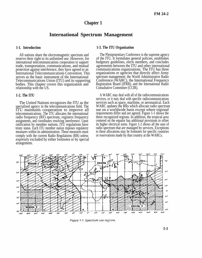
A WARC may deal with all of the radiocommunicationsservices, or it may deal with specific radiocommunicationsservices such as space, maritime, or aeronautical. EachWARC updates the RRs which allocate radio spectrumuse on a worldwide basis except where regionalrequirements differ and are agreed. Figure 1-1 shows thethree recognized regions. In addition, the tropical areacentered on the equator has additional provisions to offsetits higher electrical noise. Figure 1-2 shows all the uses ofradio spectrum that are managed by services. Exceptionsto these allocations may be footnotes for specific countriesor reservations made by that country at the WARCs.
1-1

FM 24-2
The lFRB records ITU member nation frequencyassignments. It advises the WARCs and member nationson technical matters on harmful interference and radiospectrum USe. The IFRB serves as the office of record offrequency assignments in priority and adjudicatesinterference conflicts among member nations.
The CCIR provides technical criteria on frequencysharing and examines technical and operational questionsabout international radio use. It also addresses technicallyrelated questions pertinent to ITU member nations andforthcoming WARCs. The findings of the CCIR serve asignificant influence on the state-of-the-art and as a basisfor RRs. However, these findings are recommendationsrather than having an obligatory treaty status. The CCIR isorganized into study groups. The United States StudyGroups (USSGs) submit their investigations or findingsthrough the National Committee. This is described in thenext paragraph. In addition to study groups on radiopropagation, the Army is concerned with the study groupon the mobile radiocommunications services.
1-4. The Department of State
Bilateral and multilateral negotiations and agreementsconcerning telecommunications and spectrum use are es-sential to foreign relations. The Department of State isresponsible for such negotiations. It also reviews anddirects the US positions using personnel and experts ingovernment, industry, and academic fields. It also relies onthe recommendations of the National Telecommunica-tions and Information Administration (NTIA), the FederalCommunications Commission (FCC), other governmentagencies, and private sector organizations when designat-ing delegations to international or regional ITU conferen-ces or meetings. The State Department governs USparticipation in the CCIR, and it chairs a United StatesNational Committee (USNC). The USNC consists of rep-resentatives of federal government agencies with a vestedinterest in telecommunications. The USNC gives final ap-proval on all US contributions to the CCIR. USSGs havebeen set up by charter to review foreign contributions tothe CCIR. This review helps US delegations prepare sum-maries, critiques, and impact assessments for internationalmeetings.
1-2


FM 24-2
Chapter 2
National Spectrum Management
2-1. Introduction
The Communications Act of 1934, as amended, governsradio spectrum use in the United States and its possessions(US&P). The act established duality in spectrummanagement in the US between the President for federalgovernment stations and the FCC under the direction ofCongress. The FCC regulates the spectrum use ofnonfederally operated radio stations, common carriers,and private organizations or individuals. By ExecutiveOrder 12016 of 1978, the President delegated his functionsunder the act to a new organization created as the NTIAand placed them under the Secretary of Commerce. Thischapter discusses these agencies and their functions innational spectrum management.
2-2. The NTIA
The Communications Act of 1934 gave control ofgovernment radio stations to the President. The President,through the NTIA, will--
Control all frequency resources in the US&P.
Authorize foreign governments to construct andoperate fixed service radio stations at their embas-sies. (Frequencies are assigned to these stations ifit is in the national interest and if foreign govern-ments grant reciprocal privileges to the US.)
Two committees advise the NTIA and serve essentialspectrum management functions.
The Frequency Management Advisory Council,established in 1965, consists of experts from the civil sectorwho meet when necessary to make recommendations onspectrum management and electromagnetic compatibility(EMC).
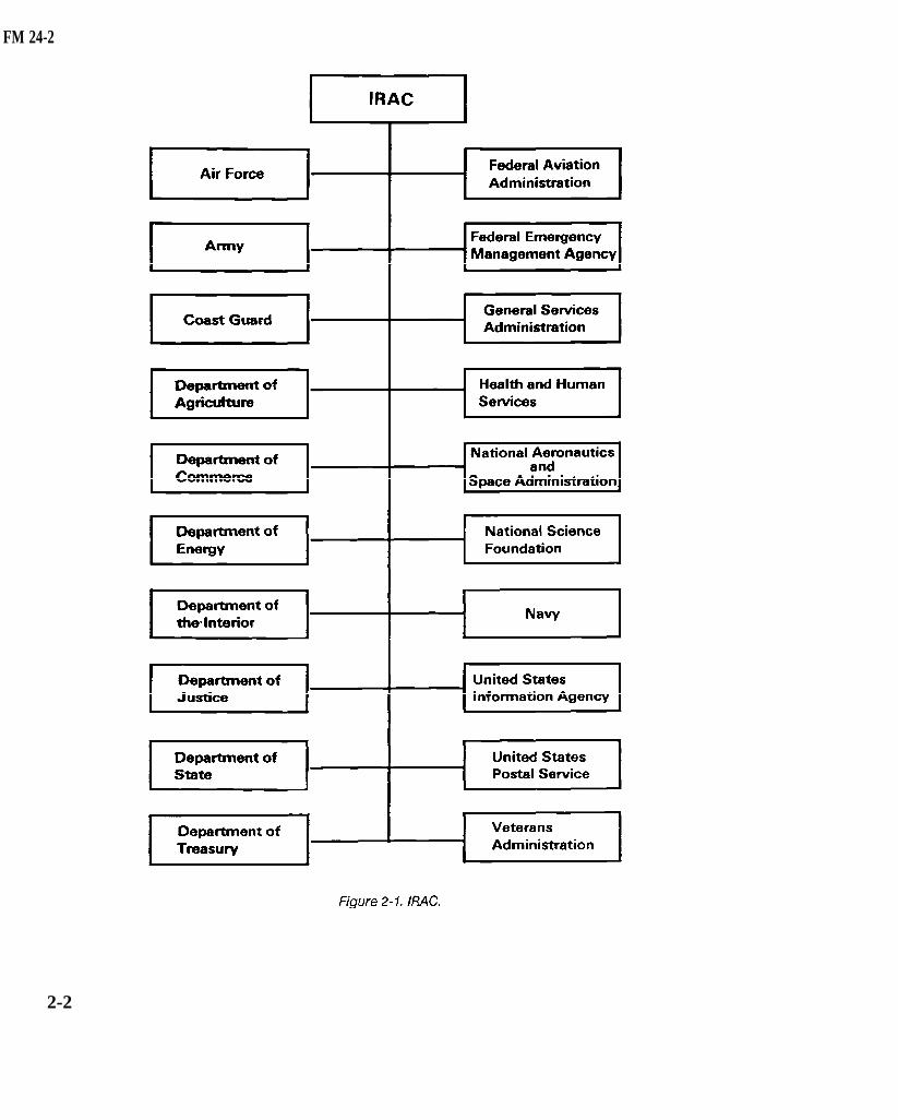
The Interdepartmcnt Radio Advisory Committee(IRAC), established by Presidential Order in 1922, is thepolicy-making agency of the NTIA. Most often, spectrummanagers deal with this committee. Figure 2-1 shows the
representatives from government departments or agencieswhich make up the IRAC.
Four subcommittees carry out the IRAC’s dailyfunctions. These are the Frequency AssignmentSubcommittee (FAS), the Spectrum PlanningSubcommittee (SPS), the Technical Subcommittee (TSC),and the International Notification Group (ING).
The FAS recommends approval of frequencyassignments for government radio stations to the Directorof NTIA. The Aeronautical Assignment Group (AAG)and the Military Assignment Group (MAG) make up theFAS.
The Federal Aviation Administration (FAA) chairs theAAG. The Navy, Air Force, and Army make up this group.The AAG approves frequency assignments foraeronautical operations.
The MAG has the same members and is chaired by theAir Force. The MAG approves frequency assignments fornonaeronautical operations.
The SPS supports the IRAC and the NTIA in planningRF spectrum allocations for established or developmentalradio services. The SPS maintains a direct liaison with theFCC.
The TSC assists the Director of NTIA on using signalequipment and techniques and in establishingperformance standards for equipment. It also researchesways of ensuring effective RF spectrum use.
The ING is responsible for all correspondence with theITU on US frequency assignments.
2-3. The FCC
The Communications Act of 1934 created the FCC asan independent government agency directly responsible toCongress. The FCC regulates nonfederal governmenttelecommunications.
•
•
2-1
FM 24-2
2-2

FM 24-2
The FCC maintains a liaison at all IRAC meetings andworks with its subcommittee even though the FCC is notan IRAC member. The liaison is the crossover point forspectrum management actions requiring FCCcoordination.
The FCC conducts its management functions under theAdministrative Procedures Act. Rule-making processesare administrated with full public knowledge and aresubject to hearings. The FCC will only act on or acceptformal statements from Headquarters, Department of theArmy. However, the FCC will consider personal matters ofArmy personnel.
The radio spectrum within the US is divided betweenexclusive government, exclusive FCC, and bands shared byboth. An example of an exclusive government band is 225to 400 MHz and is designated for military use. Exclusive
FCC management is shown in broadcasting bands.Government and nongovernment users share 60 percent ofthe radio spectrum (up to 5000 MHz).
2-4. Office of Management and Budget
Following Executive Order 12016, the Army’s right ofappeal to an unacceptable radio spectrum decision by theNTIA or IRAC is to the Director of the Office ofManagement and Budget (OMB).
OMB Circular A-11 directs that before acquiringspectrum-dependent equipment, RF supportability shallbe documented as early as possible during conceptexploration, demonstration, and validation stages. This isreflected for Department of Defense (DOD) agencies inDOD Directive 4650.1.
2-3

FM 24-2
3-1. Introduction
Chapter 3
DOD Spectrum Management
The DOD and each military service have their ownspectrum management agencies. This chapter identifiesand describes the functions of these agencies.
3-2. The DOD
The deputy under secretary for command, control,communications, and intelligence (C3I) is responsible forDOD spectrum management policy. Within the US&P, thethree military services representatives coordinatespectrum management through the IRAC. Outside theUS&P, these services coordinate spectrum managementthrough military channels.
3-3. Military Communications-Electronics Board
The Military Communications-Electronics Board(MCEB) is the main coordinating agency for signal mattersamong DOD components, between the DOD and othergovernment departments and agencies, and between DODand foreign nations. (See Figure 3-l.) The MCEBfunctions under the policies and directives of the Secretaryof Defense and the Joint Chiefs of Staff (JCS). The MCEBguides the DOD in preparing and coordinating technicaldirectives and agreements and in allocating spectrumallotments from the NTIA. DOD directives state that DODcomponents will obtain MCEB guidance before assumingcontractual obligations for developing or procuringtelecommunications equipment purposely designed toradiate or receive electromagnetic energy. Table 3-1 liststhe members comprising the MCEB.
3-4. The Joint Frequency Panel
The joint frequency panel (JFP) is the principal DODcoordinating agency for spectrum management. This panelworks closely with the IRAC’s FAS. The JFP reviews,develops, coordinates, and implements DOD directives,studies, reports, and recommendations for the MCEB.Study areas include RF engineering and management,radio wave propagation, and EMC. With the addition ofthe Coast Guard, membership in the JFP is the same as theMCEB.
3-5. DOD Area Frequency Coordinators
DOD area frequency coordinators (AFCs) coordinatefield use of RFs within designated frequency ranges andgeographic areas. Frequencies used in these areas must becoordinated with the appropriate DOD AFC beforemaking a frequency assignment. See Appendix C foradditional information.
3-1

FM 24-2
3-2

FM 24-2
3-6. Electromagnetic Compatibility AnalysisCenter
The Electromagnetic Compatibility Analysis Center(ECAC) advises and assists the Secretary of Defense, theJCS, military departments, other DOD components, andcivilian agencies on EMC matters. The ECAC maintainsthe data bases and mathematical and computer analysistechniques for investigating DOD and interservice EMCproblems.
3-7. Army Spectrum Management
The Army spectrum manager in the office of DISC4 hasthe functional responsibility for Army spectrummanagement. The Communications-Electronics ServicesOffice and close coordination with major Army commandsdirectly support the Army spectrum manager. (See AR5-12.)
The Communications-Electronics Services Officeprovides the major coordination and frequency planning atthe Department of the Army (DA) level with the Armyspectrum manager. It also supervises the operation of theArmy Frequency Management Office-Continental UnitedStates (AFMO-CONUS) at Fort Sam Houston, Texaswhich consolidated the regional frequency coordinationoffices in 1989. Army participation in the national radioregulatory structure is accomplished at departmentallevelS with the NTIA, the FCC, and other federaldepartments through the IRAC and its subcommittees.
Army spectrum management is decentralized throughmajor commands, posts, camps, stations, and operatingforces. United States Army Information SystemsCommand (USAISC) personnel manages frequencyassignment requirements locally at posts, camps, andstations. This is normally done through the Director ofInformation Management (DOIM) and forwarded toAFMO-CONUS or the Communications-ElectronicsServices Office for action. The installation manager is thefirst level of coordination for spectrum managers atCONUS Army installations. Coordination includesfrequency, equipment, power, emission, and location. •
By OMB and DOD directives, frequency allocation forArmy development and acquisitions must documentfrequency supportability before procurement. This is donethrough the JF-12 process using DD Form 1494 andnationally through the IRAC’s SPS. This task is delegatedto the United States Army Materiel Command (AMC),and by it, to the Army Communications-ElectronicsCommand (CECOM). Because of its impact withoperational frequency assignment, the plans and
engineering branch of the Communications-ElectronicsServices Office participates in the allocation to equipmentprocess with CECOM. Frequency allocations toequipment defines the frequency characteristics ofequipment being procured and indicates its frequencysupportability. Operating this equipment requires theadditional step of frequency assignment for use in theintended operational environment. EMC is the process ofpredicting and controlling potential interference inallocations planning for new equipment and for frequencysharing of the equipment in its operating environment.
Figure 3-2 shows the Army organization for spectrummanagement.
3-8. Unified/Specified Commands, TreatyOrganizations, and Other Foreign Areas
The electromagnetic spectrum is a natural resourcewithin any sovereign nations boundaries and can be usedonly with that nation’s consent. Except forced entry, theStatus of Forces Agreement (SOFA) made with hostnations defines frequency provisions and procedures to befollowed in all frequency and radio regulatory matters.
Unified commands are normally established formissions requiring significant assigned components of twoor more services. Specified commands are normallyestablished for missions requiring a force consistingprimarily of units from a single service. The highestcommand present controls spectrum management. TheMCEB provides policy guidance. Unified and specifiedcommanders, subject to host nation agreements, haveoverall management and control responsibility for all USmilitary electromagnetic spectrum use within theiroperational zones. Through the CombinedCommunications-Electronics Board (CCEB), directmilitary channels have been established between the USand the United Kingdom, Canada, New Zealand, andAustralia. Unified and specified commanders makefrequency assignments for certain intracommandcommunications provided--
Coordination has been accomplished with the government of the host nation, with local USgovernment agencies such as the FAA, the FCC,or Army, and DOD AFCs.
• National or international protection is neitherdesired nor required.
•NTIA and FCC jurisdictional areas are notinvolved.
3-3
FM 24-2
• Harmful interference with authorized usersregistered with the NTIA, the IFRB, or the hostnation will not result.
The Allied Radio Frequency Agency (ARFA) isresponsible for all North Atlantic Treaty Organization(NATO) plans, policies, and signal requirementsengineering. The US has a permanent ARFArepresentative at Headquarters, United StatesCommander-in-Chief Europe (USCINCEUR). A deputyrepresentative (at NATO headquarters in Brussels,Belgium) is the contact point for all US signal requirementsat ARFA headquarters.
In Korea, the US Forces Korea, J6 is responsible for USmilitary frequency management. He has direct liaison withthe Korean government through the Joint MilitaryFrequency Committee. This committee handles spectrummatters for all allied forces in the Republic of Korea.
There is no equivalent to the ARFA or the Joint MilitaryFrequency Committee in other treaty organizations. Eachmilitary department’s headquarters plans spectrum use
and forwards such plans to other administrations throughdiplomatic or military channels.
3-9. Electromagnetic Environmental Effects
The increasing electromagnetic density of users and thehigher powers in weapon radar systems andcommunications have impacts on electronic controls anddevices that may cause malfunctions, desensitization, andother undesired effects. These include detonation of firingsquibs, explosives, or harmful effects on personnel. This iselectromagnetic environmental effects (E3). In view of itssignificant impacts and threats to safety, this areapreviously included in spectrum management wasestablished as a separate program in 1989.
Army E3 matters are defined in Interim Guidance forthe E3 Program. It was published by the Army AcquisitionExecutive. The E3’s goal is to ensure that material willaccomplish its intended mission in the electromagneticenvironment created by strong radio/radar emitters(friendly and hostile), electrical noise pulses, or naturaleffects in peace and war.
3-4

FM 24-2
3-5

FM 24-2
Chapter 4
Tactical Battlefield Spectrum Management
4-1. Introduction
Tactical battlefield spectrum management (BSM) is thesystematic planning, managing, engineering, andcoordinating electromagnetic spectrum use by unitsengaged in combat and training for combat. At each level,the signal officer is responsible to the commander forspectrum management. At division, corps, and echelonsabove corps (EAC) levels, specially trained members of thesignal staff section perform the day-to-day BSM functions.The spectrum manager is responsible for coordination withhigher, subordinate, and adjacent units and with other staffsections.
4-2. Tactical BSM Problems
On the modern battlefield, an unprecedented numberof sophisticated systems support the commander to win thefirst battle. Most of these systems rely on theelectromagnetic spectrum.
The electromagnetic spectrum is an increasingly limitedresource. Most likely without proper management theelectromagnetic spectrum will quickly reach saturationand will seriously degrade mission performance.
Electromagnetic spectrum management was associatedmainly with selecting proper operating frequencies. On themodern battlefield, spectrum management must considershared use not only by communications systems, but alsoby intelligence/electronic warfare (IEW), data,navigational, radar, and sensor systems. Due to thepotential adverse effects, spectrum management must bean area of command interest.
In developing to the greatest extent possible aconflict-free electromagnetic spectrum usage plan,comprehensive and current information on emittercharacteristics and frequency availability is essential.Currently, spectrum management is largely a manualprocess. However, with the arrival of automated systems,maintenance of the data base for this information becomesa simpler and easier task and a more efficient process.
4-3. Importance of Spectrum Planning
The primary mission of BSM is to ensure that spectrum-dependent systems will function as intended. Themanagement process to support and control these systemsis not limited to providing frequency assignments, resolvingconflicts, and developing equipment. It also includesadvising the commander on methods to reduce his unit’selectromagnetic signature.
Coordination is the key to effective spectrummanagement. By direct coordination with higher, lower,and adjacent elements, the spectrum manager can reduceor omit harmful interference from friendly forces.Coordination with the spectrum manager havingassignment authority for a specific frequency or frequencyband is required before conducting IEW operations. Thiscoordination reduces any adverse impact on friendly forcesand helps to increase effectiveness of friendly IEW.
Spectrum management must be involved in developingspectrum-dependent equipment. To ensure new systemscan perform as designed, EMC analysis and otherprocedures must be followed as described in AR 5-12.Systems, especially tactical systems, must be designed tooperate in any of the ITU’s three regions. The frequencyallocation tables of nations where systems can reasonablybe expected to be deployed must be considered during thedevelopment phase.
4-4. BSM Functional Tasks
At each tactical level, the signal officer is responsible tothe commander for BSM. At division, corps, and EAClevels, the signal officer relies on the signal staff section toperform the day-to-day spectrum management functions.These functions are broken down into four basiccategories. They are--
Spectrum apportionment.
Data base maintenance.
•
•
4-1

FM 24-2
Interference resolution. Jammers.
Spectrum signature assessment.
The spectrum manager with the electronic warfareofficer (EWO) establishes and updates a joint restrictedfrequency list (JRFL). This list is based on the G3 prioritiesfrom the commander’s guidance. (See Appendix J.)
The traditional perception of spectrum management isthat it consists solely of apportioning spectrum to the user’sequipment. On the modern battlefield, this continues to beimportant. The five subfunctions of spectrumapportionment are--
Determining spectrum requirements.
Obtaining required resources.
Matching resources to requirements.
Distributing resources to the user.
Evaluating and optimizing spectrum use.
Battlefield spectrum requirements are determined bythe user’s operational needs. Based on doctrine andexperience, the spectrum manager must make a goodestimate of a unit’s spectrum requirements. The operationand the equipment available determine the actualrequirement. This data is drawn from operation orders(OPORDs), standing operating procedures (SOPs), andcoordination with unit signal officers. The data will becategorized as follows:
VHF-FM.
VHF-AM.
UHF-AM.
4-2
UHF-FM.
HF ground wave.
HF sky wave.
Multichannel communications.
Satellite.
Radar.
Air ground.
Data links.
Data distribution systems.
Navigational aids.
Sensors.
Directed-energy weapons.
Frequency restrictions - All radios for a particular netmust be able to operate on the same frequency. Netfrequencies must be assigned with primary considerationgiven to the older series radio’s tuning capabilities. Thisalso applies to channel spacing. For example, the olderseries of VHF-FM radios has a channel every 100 kHz, thecurrent series every 50 kHz, Single-Channel Ground andAirborne Radio System (SINCGARS) and the new squadradio (AN/PRC-126) every 25 kHz. Nets involvingdifferent radios must consider these differences.
COMSEC considerations - The AN/VRC-12 series canoperate with the KY-8/38 (NESTOR) or KY-57(VINSON). The SINCGARS series only operates withVINSON. Therefore, nets with different COMSECdevices or mode of operation cannot operate in theSECURE mode.
Frequency resources are obtained from elements atEAC. Normally, a corps receives its resources from thetheater spectrum management authority; a divisionreceives its resources from the corps. The earlier theplanner identifies the spectrum requirements, the easier itis for the spectrum manager to obtain the necessaryresources. Every effort is made to obtain and pass onresources with the fewest restrictions allowing usersmaximum flexibility.
Resources are matched to requirements throughcoordination, allocation, allotment, and assignment.Coordination is a never-ending process and is essential toan effective spectrum management program. Allocation,allotment, and assignment have distinctly differentmeanings than they might have in normal use.
Allocation is establishing frequency bands for specificfunctions or radio services such as broadcast, fixed, andmobile. When authorizing more than one type of service in

FM 24-2
a band, rank services as primary, permitted, or secondary.Primary and permitted services have equal rights except inpreparing frequency plans. The primary service has firstchoice of frequencies. Secondary services are on anoninterference basis (NIB).
Allotment is establishing specific bands or frequencieswithin a prescribed nationally or internationally allocatedband.
Assignment is the authorization given by the properauthority for a radio station to use an RF or radio channelunder specified conditions. Assignment is the main methodof matching resources to requirements.
Once resources are matched to requirements, theassignments are distributed to the users. FM 24-16 detailsthe formats for disseminating signal information. Theprimary means of distributing VHF-FM, VHF-AM, andUHF-AM assignments is the signal operation instructions(SOI). MSE LOS multichannel system assignments withinthe division are done by the division signal battalion.Within the corps, assignments are done by the corps signalbrigade.
Constant review optimizes spectrum use. Systemefficiency, effective spectrum use, and changes in the unitmission are analyzed ensuring the tactical commanderreceives the required support.
4-5. Spectrum Apportionment Tasks
Most requirements are identified at division level andpassed to the division spectrum manager. If the divisionspectrum manager does not have the resources to fill therequirement, he requests support from the corps spectrummanager. Similarly, if corps does not have the resources,the request is passed to EAC. At EAC, many variationsoccur in the spectrum manager’s processing of the request.The EAC spectrum manager does not necessarilyrepresent one level or agency. He can be located at post,camp, stations, theater Army, unified command, Army, orDOD levels.
The ITU recognizes that the electromagnetic spectrumof each sovereign nation is, within its territory, as much anatural resource as any mineral, and is therefore subject tothat nation’s regulation. The ITU publishes allocationtables in which member nations should adhere. Most ITUmember nations (and even nonmember nations) stay fairly
close to the ITU tables when developing nationalallocations. A commonality of 80 percent or more isnormally found between the ITU tables and those of a givennation. However, a nation may use its spectrum resourcesin any way as long as it does not interfere with spectrumusers outside its national borders.
In most nations, only one agency allocates and assignsfrequencies such as a communications ministry or theagency controlling the post and telecommunications or itsequivalent. The two agencies within the US&P are: theNTIA/IRAC for federal government users and the FCC forcivil and nonfederal government users. Military assignmentactions that take place in the US&P fall under theNTIA/IRAC umbrella. In the US Army, assignmentauthority is seldom found below the division level.
In the ITU region 2 (North and South America), theband 225 to 328.6 MHz has a primary allocation to the fixedand mobile services with a small allocation (267 to 273MHz) to the space operation (telemetering) service. TheUS tables have a government-only allocation to the fixedand mobile services throughout the entire band with noaccommodation for space operation or civil use. The UStables are footnoted to limit operations primarily to themilitary services. The NTIA manual gives the MAGmanagement authority for the band. The militarydepartments, in their MCEB role, have collaborated on anallotment plan that segments the band into 25 kHzchannels. Each channel is designated for MAG use or fora functional use (such as joint radio relay). The DlSC4 hasrecorded several of the Army designated channels in theIRAC government master file as group assignments (forexample, 234.700 MHz US-wide). This group assignmentgives the US Army authority to use 234.700 MHz anywherewithin the CONUS. The Army AFCs may then beauthorized to manage this frequency within theirrespective geographic regions. The AFCs may delegatethis assignment authority to corps in their region, who mayfurther delegate the authority to subordinate divisions.
Spectrum requirements must be determined as early aspossible during operation planning or during equipmentdevelopment stages. Obtaining frequency resources can bea complex and time-consuming process. It can take a fewdays to several months. Frequency support may take yearsto coordinate. Examples are newly developed signalsystems, satellite systems, and American Forces Networkstations. These actions usually begin at levels above corps.
4-3

FM 24-2
Sometimes, short notice requests are not fulfilled at all, orthe resources provided are less than optimal.
The accuracy of a frequency request can make thedifference between mission success and failure. Thepreparer must ensure that all necessary data is includedand correct. This data includes radio emission designators(Appendix D) and station classes (Appendix I). Next, thepreparer must justify the requirement is mission essential.Nice-to-have requests cannot be supported in theincreasingly congested radio spectrum. Spectrummanagers at EAC, and especially those at national levels,must insist on knowing the operations - why it is neededand how it will be used.
At all levels of spectrum management, the spectrummanager must be sure to submit accurate and completefrequency requests. Introducing inaccurate or incompletefrequency requests into coordination channels can resultin delays and denials. The requesting spectrum manageralso risks losing credibility. Future requests will be met withincreased scrutiny by the coordinating/approving agencies.Credibility loss is particularly damaging when dealing withhost nations. Spectrum managers must be extremelyconscientious in maintaining credibility.
Spectrum management is basically a bottom-top-bot-tom process. The spectrum requirements are identified atlower echelons. Then, the frequency request is forwardedup through spectrum management channels until it reachesa level where resources are available. The frequency as-signment notification is then sent down through those samechannels until it reaches the requestor. Appendix A con-tains baseline BSM tasks.
4-6. Data Base Management
Equipment technical characteristics are required toapportion the spectrum and to resolve interference. Thesecharacteristics include equipment tuning range, emission,channelization, and method of tuning (crystal, continuous).Outputs of the apportionment process (such as SOI,multichannel diagrams, and other frequency use records)are basic to the whole concept of effective BSM. Throughthe data base, the spectrum manager should have acomplete list of spectrum-dependent equipment in hisarea.
A spectrum manager’s database may include frequencyassignment records, documents containing signalequipment parameters, frequency allocation tables, lists,
and indexes, equipment allocation documents, ITU andnational RRs, military regulations, manuals, andpamphlets, and various other tools of the trade.Assignment records require maintenance on a continuousbasis. Maintenance of the spectrum manager’s data baserequires maintenance on an as-needed basis.
The spectrum manager uses several documents asfrequency assignment records. The EAC spectrummanager issues the current assignment list. It reflects allpermanent frequencies authorized for use by the unit.However, it does not contain specific uses for allfrequencies listed. The SOI provides a record ofassignments in certain bands. The NSA organization netlist and sequential frequency list show the SOI assignmentsin different formats. Non-SOI frequencies may be kept inseveral different forms. These can include multichanneldiagrams, assignment messages, memorandums,handwritten or typed lists, or even 3 by 5 cards. There is nostandard. Likewise, methods and techniques formaintaining the records are not standardized.
Records maintenance is primarily done by manualmethods. However, maintenance automation shouldbecome the norm rather than exception. Spectrummanagement requires spectrum managers to be computerliterate. Plus, automation resources should be available fordata base management to aid the spectrum manager toeffectively apportion limited resources.
4-7. Interference Resolution
Interference is defined as the radiation, emission, orindication of electromagnetic energy, unintentionallycausing degradation, disruption, or complete obstructionof the designated function of the electronic equipmentaffected. (See Appendix B.)
Interference resolution is handled at the lowest levelpossible. The spectrum manager is the final authority ofinterference. Interference may come from signal devices(such as unintentional friendly and unfriendly radios andradars) and from nonsignal devices (such as welders orvehicle engines).
After being informed of unresolved interference, thespectrum manager or a member of his staff can--
• Seek the EWO’s assistance in identifyng thesource.
4-4
FM 24-2
•
•
•
Advise physical relocation of the affected user.
Advise tolerance of the interference (workingthrough it).
Make appropriate changes in assignments.
The EWO or G2 may detect hostile interference orjamming before it is recognized and reported to thespectrum manager. In such cases, the coordination ofinterference should be initiated in reverse to ensure thatineffective signal functions are recognized and corrected.A Meaconing, Intrusion, Jamming and Interference(MIJI) report may be initiated. AR 105-3 details MIJIprocedures. FM 24-33 contains further information oninterference and hostile jamming.
Commands handle MIJI actions differently. Somecommands have the electronic warfare (EW) staff elementprimarily responsible for MIJI actions, while others havethe spectrum manager responsible for MIJI actions. Insome commands, the initial MIJI report is sent directly tothe Joint Electronic Warfare Center (JEWC). Othersrequire the initial report be reviewed by either or both theEW and BSM staff before forwarding to the JEWC.
The first three elements of MIJI, MIJ, are of primaryinterest to the EW community. The fourth element, I, is ofconcern to the spectrum manager. In most commands, theEW staff, in cooperation with the spectrum manager andother staff elements, takes the lead in resolving MIJincidents. The spectrum manager directs interferenceresolution efforts.
The initial MIJI report should be sent to the battlefieldspectrum manager. He has the data base to check quicklyfriendly frequency assignments. He may go to the nexthigher level spectrum manager for assistance. Hedetermines whether the action will be handled as MIJ or I.If MIJ is determined, action is normally transferred to theEW element. MIJ actions are diagrammed separately fromI actions. (See Appendix A.)
The skill of signal systems operators and maintenancepersonnel can mean the difference between minorinconvenience and complete system disablement. Onexperiencing harmful interference, the operator should beable to discern whether the interference is coming fromnatural phenomena or man-made sources.
If natural phenomena are the cause, the operator shouldtry to work through the interference. Should it persist, aBSM coordinated frequency change may be in order.
If the operator suspects man-made interference, hemakes an internal equipment check to exclude equipmentmalfunctions. In many cases, improper alignment,degraded components, antenna disorientation, or poormaintenance is the culprit. After the operator has ruled outinternal causes, a check with other friendly units in the areamay reveal incompatibilities between operations. If acompromise cannot be worked out between the units, thecase is referred to the spectrum manager at the next higherechelon.
If interference cannot be identified through localchecks, a MIJI report is submitted to the JEWC and Armyaddressees, as directed. The spectrum manager thencontinues to take whatever actions required to resolve orminimize the interference.
The JEWC analyzes the report and submits an analysisback to the reporting unit and intermediate addressees.This aids in resolution. However, the JEWC is notresponsible for resolution. Resolution responsibility lieswith the local unit and its higher headquarters. If outsidetechnical assistance is required, it can be requestedthrough the United States Army Information SystemsEngineering Command (USAISEC) at Fort Huachuca,Arizona. Natural-phenomena interference andfrequencies assigned as NIB are not reported to the JEWC.(See Appendix F.)
Deconfliction is the process of optimizing the use of theelectromagnetic spectrum. It incorporates therequirements of the battlefield spectrum managers and theIEW community. The BSM function is basically one ofplanning; in contrast the IEW management functions aremainly concerned with taking advantage of combatopportunities. The spectrum manager must manage theelectromagnetic spectrum and be responsive enough topermit IEW missions to be conducted againstopportunities if they arise with minimum constraints.
The spectrum manager must know the characteristics offriendly force intelligence systems and EW emitters. Hemust be an integral part in the planning and operating ofIEW missions for deconfliction to work.
4-5

FM 24-2
The JRFL only protects against cochannel interference.For deconfliction to work, BSM requires automationcapability together with the technical characteristics ofemitters to do adjacent channel, harmonic andintermodulation to prevent interference to friendly forces.
Before beginning the deconfliction process, assemblethe following data:
•
•
•
•
•
•
•
•
•
•
•
•
•
•
4-6
Formation orders of battle.
Tactical grouping for current and futureoperations.
A comprehensive diagram of everycommunication and electronics net used. (Thisincludes equipment types, antenna types, andfrequency requirements.)
A list of nets showing the power used and rangesover which they should operate.
The frequency list allotted by higherheadquarters, including power and/or restrictions.
Mutual interference, characteristics of potentialcommunications-electonics (CE) equipment tobe deconflicted (intermediate frequencies are ofparticular importance).
A list of known bad frequencies (frequencieswhich exist in the electromagnetic environmentwhich are beyond the direct control of thecommanders).
A list of frequencies or bands planned to be usedby friendly jammers.
Spectrum use by the enemy.
Ground and sky wave charts for the area ofoperation, updated by ionospheric soundingswherever possible.
Spectrum signature data and characteristics ofthe equipment the IEW units plan to deploy insupport.
An initial list of relative priorities from the G3based on the commander’s guidance. (Whenlarge numbers of spectrum dependent equipment
will be located within close proximity, it may notalways be possible to assign noninterfering fre-quencies to all users. Thus, it is essential to estab-lish a system of priorities for frequencyreassignment if such equipment becomes in-volved in the deconfliction process.)
Links that are inflexible and usually use fixed frequencies (such as emergency services,international distress frequencies, and air trafficcontrol). These must be taken into account in theJRFL. (See Appendix E.)
A JRFL and a method of maintaining currency while operations are in progress. (The JRFLmust be continually revised to includeredeployment of maneuver units, changes in EWplans, and changes in enemy EW readiness.)
The deconfliction process benefits the IEW staff with areal time and planned spectrum data base of friendly forcespectrum assignments and their locale. The IEW staff usesthis information to process out friendly force emitters whenidentifying and locating enemy emitters. Using thisinformation, they coordinate with the spectrum managerwhen they recognize friendly force emitters are degradingtheir mission effectiveness by masking enemy emitters. Byusing the data base, the IEW staff detects and locatesenemy electronic countermeasures (ECM) and itsspectrum capabilities. It uses this information to predictand advise the spectrum manager which friendly forcecommunications and electronics systems will not meettheir mission, when they should take evasive actions, orwhen to activate their electronic counter countermeasures(ECCM). The spectrum manager provides guidance tofriendly force communications and electronics systemspersonnel. In many cases, the IEW staffs advice preventsunnecessary testing by friendly force personnel indetermining if they have an equipment failure or are beingsubjected to enemy EW.
Should there be conflict between the spectrum managerand the IEW staff on deconfliction, the G3 has finaldecision authority.
4-8. Spectrum Signature Assessment
A spectrum signature is the distinct pattern of spectralemanations from a device or collection of devices. Thesedevices include signal equipment, power generators,vehicle engines, welders, and the radiation from command

FM 24-2
post (CP) facilities. These facilities include radio parks,airfields, motorpools, and forward area rearm/refuelpoints. A pattern is formed by several variables: time ofday, geographic area, number, type, frequency, and powerof emitters. These variables make up an identifiableelectromagnetic signature.
The spectrum manager is the point of contact forspectrum signature vulnerability. This is a subordinate partof his responsibilities as the emission control (EMCON)officer. EMCON also includes considering heatemanations from engine blocks that infrared devices candetect. EMCON and effective implementation of ECCMare the spectrum manager’s responsibility. For example,the spectrum signature assessment portion of ECCMrelates to the spectrum manager’s responsibility todetermine the distinguishing characteristic of theemanating patterns. ECCM procedures, the SOP, or theECCM annex to the OPORD point out steps in preventinga sophisticated threat radio electronic combat unit fromidentifying targets through frequency spectrumemanations. FM 24-33 outlines ECCM procedures. Everysignal system user should read and practice the techniquesdescribed in FM 24-33 and ACP 125, US Supplement 1.
The objective of spectrum signature assessment is toevaluate the degree to which the unit’s facilities areidentifiable by their spectrum signature and to advise thecommander on ways to lessen the command’s vulnerability.TRADOC Pamphlet 525-23 refers to signature assessmentas a BSM responsibility.
4-9. Division BSM
The division is the largest maneuver element in theArmy. The division, however, is not alone in its area ofoperation, and these other units impact on the division’sspectrum use. The division commander, through thedivision signal officer (DSO), has authority over spectrumuse in his area of operation. This authority does notnecessarily extend to corps, EAC, other services, or alliedforces in his area. Coordination is the division G6’s key tosuccess in providing effective and flexible spectrum use.
FM 11-50 contains the specific personnelresponsibilities for division BSM. For this discussion, thekey personnel are the DSO, the division G6 (formerlyassistant division signal officer (ADSO)), the radio officer,and the spectrum management NCO.
The DSO, as the signal battalion commander, isresponsible for BSM within the division. The radio officerand the spectrum management NCO serve as members ofthe division G6 staff. They perform the day-to-day BSMfunctions.
The radio officer/spectrum management NCO has staffsupervision over all radio communications established inthe division. The radio officer/spectrum managementNCO works for the division G6. However, he coordinatesclosely with the division signal battalion S3 when preparingmultichannel systems diagrams. The radio officer does notcoordinate frequency use or frequency allocation tomultichannel systems. This is the S3’s duty. (See AppendixG.) The radio officer provides the S3 current and futuredivision unit locations and circuit requirements. The S3prepares the radio relay diagrams. The radioofficer/spectrum management NCO--
•
•
•
•
•
•
•
•
•
Prepares and issues radio net diagrams for thedivision nets.
Maintains an RF use register and map to ensurean up-to-date RF assignment for all systemsexcept multichannel.
Supports the division tactical CP as the divisionG6 representative.
Prepares items of the division SOI on radiomatters.
Coordinates frequency assignments to aid infrequency compatibility within the division andwith adjacent divisions.
Is responsible for distributing frequencyinformation associated with the SINCGARS andother frequency-hopping (FH) equipment. (SeeAppendix H.)
Coordinates with corps for hopsets andtransmission security (TRANSEC) codes.
Implements TRANSEC policy within the division.
Is the point of contact for MIJI and all ECMoperations.
4-7

FM 24-2
4-10. Corps BSM kilometers wide by 250 kilometers deep. Theelectromagnetic spectrum management of this areaincludes the airspace above it. Emerging AirLandOperations doctrine is changing the corps area from linearto nonlinear. It will also greatly extend the corps area. (SeeFigure 4-2.)
The corps is the Army’s principal force in the theater ofoperations. Figure 4-1 shows a typical corps structure. Themake up of the corps varies with mission requirements. Itcontrols up to five and two-thirds divisions and selectedcombat support and combat service support units.Examples are the military police, military intelligence,psychological operations, civil affairs, and US Air Forceweather units. The corps can cover an area as large as 140
FM 11-92 covers the specific personnel responsible forcorps BSM. Their titles and general responsibilities arediscussed in the following paragraphs.
4-8

FM 24-2
The corps signal officer (CSO) who is the corps signalbrigade commander is responsible for BSM within the
At corps level, the radio frequency officer/spectrummanagement NCO and the radio systems officer serve as
corps. The CSO-- members of the corps G6 staff. They perform the
•
•
•
•
•
•
•
•
Advises the commander of spectrum impacts ofplanned combat operations.
Indicates any possible conflicts betweenbattlefield functions based on spectrumavailability and proposes appropriate solutions.
Ensures the performance of BSM functions.
Advises on all signal matters.
Exercises technical staff supervision over corpssignal activities.
Coordinates frequency assignments andinterference problems.
Assists in preparing EW plans and annexes.
Advises the corps commander on
•
•
•
•
•
•
• •
•
electromagnetic radiation matters.
The CS0 as the signal brigade commander--
Commands and controls all assigned andattached signal units.Performs communications system planning,engineering, and control functions.
day-to-day BSM functions.
The radio frequency officer/spectrum managementNCO--
Coordinates frequency assignments.
Serves as the point of contact for MIJI and allECM operations.
Prepares SOI items pertaining to spectrummanagement.
The radio systems officer--
Exercises staff supervision over radiocommunications activities.
Prepares SOI items pertaining to radiocommunications.
Coordinates with the radio frequencyofficer/spectrum management NCO.
Prepares SOIs, plans, and orders for the corpsheadquarters, the headquarters of majorsubordinate commands, and various groundliaison nets.
4-9

FM 24-2
Specific BSM staff functions include--
•
•
•
•
•
Allotting/assigning/coordinating frequencies tosubordinate commands.
Coordinating implementation of effective dates ofSOI editions and time period changes to radionets of nondivisional corps units.
Maintaining reserve frequencies in allappropriate bands for contingency, systemsrestoration, and antijamming operations.
Coordinating and implementing BSM.
Maintaining a complete and current data base onspectrum use in the corps area of operations.
At the signal brigade headquarters, the systemsengineer--
•
•
•
•
•
Evaluates radio propagation data for brigaderadio networks.
Assigns frequencies to units in the brigade.
Coordinates RF requirements.
Maintains records, prepares reports, and initiatescorrespondence to corps headquarters onbrigade RF matters.
Is responsible for engineering radiocommunication systems.
One spectrum management NCO assists the systemsengineer. The CE officer and the radio officer assist thesystems engineer in preparing engineering plans.
The systems engineering staff of the corps signal brigadeS3 is responsible for spectrum management to support themobile subscriber equipment (MSE) mission andengineering its communications systems.
4-11. SOI and Spectrum Management
The SOI is a COMSEC aid and a spectrum managementdocument. The US Army Communications ElectronicsServices Office SOI Detachment at Fort Meade, Marylanddesigns SOI based on unit input requirements for centralproduction at the NSA. FM 24-35 contains instructions onSOI. Current DA policy limits the centrally-produced SOI
to separate brigades or larger size active Army and Reserveunits, except in cases authorized by Headquarters, DA,DISC4 through the US Army Communications-Electronics Services Office. Those units not authorized toreceive the centrally-produced SOI will make amanually-produced SOI following FM 24-35.
The signal officer at corps, division, and separatebrigades and below are responsible for the unit SOI. Thework sheets for each unit are filled out in accordance withFM 24-35 and are sent to the NSA. The NSA will enter thedata base from these work sheets into the required formatfor the computer programs. The SOI is generated from thisdata base, proofread for errors, corrected, regenerated ifnecessary, printed, packaged, and shipped by ArmedForces Courier Service (ARFCOS) or commercial carrier.It is delivered to the COMSEC account number servicingthe controlling authority for the SOI. Once distributed, itis protected like all similarly classified material. The SOI contains call signs, frequencies, suffixes, expanders, andpasswords which change at least once every 24 hours.
Tactical call signs are letter-number-lettercombinations. Units that normally operate together in a netor nets have last-letter-unique call signs. Once a net isestablished, only the last letter of the call sign and a suffixare used by those units. This reduces transmission time andmakes it more difficult for a threat force to identify a unit.Suffixes and expanders are used to further identify a userwhere confusion could otherwise result. Other SOIs maybe manually produced as required with prior approval ofthe controlling authority. Three basic SOI are a trainingSOI, an operational/reserve SOI, and an exercise SOI.
A training SOI is used during routine classroom,garrison, and field training situations for which exerciseSOI are not produced. At least three ten-time period(30-time period total) SOI editions should be prepared.These editions are rotated to simulate operational use andare reused until replaced. Replacement is usually causedby unit reorganization, major frequency allocation, ornormal wear and tear.
An operational SOI is used for daily operations. Areserve SOI is the next time period’s operational SOI. Theterm operational/reserve refers to either SOI. However,the reserve SOI is always the contingency SOI. At leastthree ten-time period SOI editions should be prepared byunits preparing manual SOI. Units receiving the centrallyproduced SOI are normally provided 180 time periods ofoperational/ reserve SOI.
4-10

FM 24-2
An exercise S01 prepared as required is for fieldtraining situations where the training SOI will not suffice.At least two ten-time period SOI editions should beprepared to permit supersession/rotation actions asappropriate. Units receiving the centrally-produced SOIare normally provided at least 30 time periods (threeeditions) of exercise SOI.
The contents of a specific SOI depend on therequirements of the using command. The signal officer,who assumes overall managerial responsibilities of thesystem for the commander, determines item contentsbased on command mission requirements. All SOI containstandard items with each item following a standard format.The items are printed in pocket-sized books (4 1/8 by 4 3/4inches). Each book contains ten time periods (except theBattlefield Electronic CEOI System (BECS) which hasonly five) of changing information.
The centrally-produced SOI is designed to meet theneeds of the using command and item contents may varyaccordingly. Each document normally contains--
•
•
•
•
•
•
An index.
Changing call signs and frequency assignments.
Changing suffixes and expander assignments.
•
•
•
•Pyrotechnic and smoke signals.
Signs and countersigns.
Supplemental instructions for use of the aboveitems.
(Nonchanging standard items include medicalevacuation procedures, net radio interface (NRI),switchboard designators, and similar SOP items. There are20 standard items. A unit may select any number of theseitems or none.)
The centrally-produced SOI has an organization net list(ONL) of all nets and their assigned frequencies for eachtime period. A sequential frequency list (SFL) is alsoproduced. It contains all the authorized frequencies usedin that SOI and the nets to which they are assigned for eachtime period. These lists may be used to identify and resolvefrequency interference problems.
The corps spectrum manager manages single-channeland FH tactical combat net radios using the SOI process.
He coordinates and distributes the SOI to corps assignedunits, less the divisions. The signal officer is responsible forBSM support to all corps units. The SOI contains changingfrequencies, call signs, and suffixes. BSM personnelmanage all radio-related SOI items for corps-based units,and the frequency resources issued to divisions forinclusion in each division SOI.
Currently, all active component corps use the NSA’scentrally-produced SOI. Corps BSM personnel perform acoordinating function in this automated SOI program. Ifcorps level units produce the SOI manually, the radiofrequency officer/spectrum management NCO is directlyresponsible for implementing the radio-related SOI itemsfor corps-based units. The radio frequencyofficer/spectrum management NCO will furnish guidanceto subordinate commands on frequencies, call signs, andsuffixes to be used within these commands.
Because of the flexible organization of the corps, BSMtechniques used may vary from those at division. Factorsthat determine the techniques are--
The corps organization.
The deployment and employment of operatingmaneuver forces.
The type of operation in which the corps isengaged.
The CE systems that support the operation.
The requirements of subordinate divisions, corpssupport units, higher headquarters, and units of otherservices in the corps area will also influence themethodology of corps BSM.
The corps spectrum manager delegates spectrummanagement authority for multichannel radio equipmentto some units within the corps. These units include thecorps signal brigade, the air defense artillery, and the aircavalry combat brigade. These particular units are allottedfrequencies for line of sight (LOS) radio systems. In turn,the signal officers of those units assign frequencies fromtheir allotments based on system engineering criteria.
There is a requirement to change call signs andfrequencies (HF, 2 to 30 MHz and VHF-FM, 30 to 88MHz) on tactical radio nets daily. The spectrum managerallots the frequencies to the divisions and assignsfrequencies for corps troop units. For independent
4-11

FM 24-2
operations by corps elements configured into task forceunits, the spectrum manager may choose to issue frequencyallotments if the organizational area of that taskorganization will not conflict with the corps main area ofoperations.
For special signal equipment and temporary frequencyassignments, the spectrum manager processes requests ona case-by-case basis. He also maintains locally generatedrecords of each assignment for future reference. The useof weapons and special-purpose systems will beprecoordinated with the spectrum manager, inputted intohis data base, and used as required based on thedeconfliction process.
BECS automates and decentralizes SOI production onthe battlefield. It also provides automated spectrummanagement data for SINCGARS. BECS generates SOIdata and SINCGARS spectrum management data. Thisdata is displayed, printed, stored, and electronically loadedor transferred by SINCGARS radios. The electronic BECSSOI will eventually replace the NSA’s centrally-producedpaper SOI. The BECS spectrum management datagenerates TRANSEC key to meet the unique ECCMrequirements of the SINCGARS HOPPING mode. BECSis more responsive to rapidly changing and highly mobilebattlefield conditions through SOI decentralization. It isused as an integral subsystem of SINCGARS, improvedhigh frequency radio (IHFR), short term antijam (STAJ),and other VHF (AM/FM), UHF, and HF radio systems.See FM 11-32 for further details.
4-12. Corps Area Airspace
Air Force and Navy close air support and organic Armyaviation support to the ground commander present asignificant additive inventory to the emitter density withinthe corps area of operations. The air-ground operationsystem includes the Army air-ground system and the AirForce tactical air control system. It extends throughout themajor echelons of corps to perform reconnaissance,surveillance, fire support, and airlift. Extensivecommunications support to these elements is essential toensure responsive, coordinated use of the corps airspace.Collocation of these facilities with the echelons of corpsdictates their unique spectrum-dependentcommunications be harmonized and integrated among thecompeting demands for limited resources.
The corps commander is responsible for coordinatingairspace activities. The spectrum manager is responsible tothe commander for the electromagnetic environmentwithin that same zone. He must be aware of any air activitywhich could interfere with ground maneuver unitcommunications. The spectrum manager can advise thecorps commander on possible mutual interference andreduce any harmful effects on command and control of thecorps. Coordination can increase air activity and groundactions by preventing interference. Assigned and attachedArmy aviation units use corps spectrum resources allottedto them. Air Force units, using frequencies in the bandsallotted by EAC, require coordination with the corps BSMstaff to avoid possible interference. The airspacemanagement elements under the G3’s staff supervision andthe corps BSM function as focal points where airspacerequirements can be met, and where airspace frequencyproblems can be resolved.
Another source of information for spectrumcoordination is the US Air Force tactical air control center(TACC). It is responsible for airspace control, groundtactical sensor surveillance, air support, and air strikecoordination and control. The airspace managementliaison section at the TACC coordinates integrating Armyair traffic control facilities. This coordination involvesintegrating flight operations centers, flight coordinationcenters, approach/departure control facilities, airfieldcontrol towers, and navigational aids furnished by thecorps air traffic control. Thus, the TACC is another sourceof information and liaison for coordinating spectrumresources used by Army traffic control facilities.
The corps area is divided into a tactical operations areaand a rear operations area. The dividing line between thetwo is defined as the rear boundary of the frontlinedivisions. Procedures for airspace control andcoordination within the two areas are defined in terms oftraffic movement and electronic control. The interfacepoint for integrating the corps and the air forces is thebattle coordination element (BCE) located at the TACC.The corps representatives in the airspace managementliaison section are members of the BCE. They coordinatecorps requirements to operate aircraft and/or weaponsystems within the airspace over the corps. Therefore,Army representatives in the TACC help the corpsspectrum manager resolve airspace electromagncticspectrum problems.
4-12
FM 24-2
4-13. Corps Air Defense Artillery Operations
Air defense artillery weapons use within the corps isintegrated into the force commander’s scheme ofmaneuver. Theater Army air defense artillery units(brigades and battalions) are normally placed to supportthe corps. It may be an Army air defense command,brigade, or battalion depending on the size of the theaterof operations, the number of air defense artillery battalionsassigned, and the corps commander’s stated requirements.Nondivisional air defense artillery units in the corps area(HAWK, PATRIOT, SHORAD) establish internal andexternal radio nets, internal multichannel radio systems,semiautomatic command and control systems, and radarequipment. Their use must be coordinated with thespectrum manager. Their CPs are integral parts of theairspace control system which regulates firing of airdefense weapons and prevents undue interference withother operations. The corps spectrum managercoordinates spectrum resource use and resolves competingspectrum assignments to minimize mutual interference.
4-14. Military Intelligence Combat ElectronicWarfare and Intelligence
Military intelligence combat electronic warfare andintelligence (CEWI) units will be deployed throughout thetheater area and will provide assistance in EW,interference, and jamming. The CEWI staff includes anEWO who can be consulted on EW matters. Militaryintelligence CEWI units supporting the division, corps, ortheater may be requested to identify and locate aninterference source.
Communications is essential to intelligence operations.With the integration of all intelligence, security, and EWassets into one unit, the military intelligence CEWI’smission dictates using the electromagnetic spectrum, plusresources for command and control of its own units. CorpsG2, G3, EW, and BSM personnel must closely coordinatewith each other to optimize command and controlcommunications while effecting EW operations against thethreat force. The basic task for the spectrum manager is toanalyze the impact of proposed IEW operations oncommand designated priority command and controlcommunications. The G3 has final decision authorityshould any conflict between the IEW staff and BSM staffoccur.
4-15. EAC BSM
EAC command structure is normally that of a UStheater. EAC may include US-only headquarters, theaterArmy, a joint task force, and/or a headquarters containingpersonnel from more than one nation. Since peacetimemilitary forward deployments exist, US Army forces mustoperate within Allied command relationships to obtainhost nation support which includes spectrum assets. Figure4-3 shows a typical US national chain of command for atheater of operations. BSM coordination lines will parallelthese command lines for national spectrum-relatedactivities.
4-16. Unified Command BSM
In all overseas commands involving large geographicarea and services, a unified command is established for atheater of operations. The major Army, Navy, and AirForce headquarters are component commands within thetheater.
Spectrum management for US military forces in anoverseas area is under the control of the highest commandpresent. In a unified command, the JCS provide policyguidance, and the overseas commander provides theaterguidance to the component commands. The theatercommander exercises control over electromagneticspectrum use within the theater through his joint staff. TheJ6 has primary staff responsibility for spectrummanagement in the theater. The J6 office includes trainedspectrum management personnel who are responsible forthe allotment and assignment of all frequencies used byforces within the theater or zone of operations.
In most cases, the theater of operations involves Alliedforces and the unified command in a combined operation.Moreover, some allies use and manage the spectrumdifferently from their US counterparts. Since manyvariations exist in providing definitive guidance, it isessential that US Army spectrum managers realize this andprepare to adjust to the combat situation. It is also essentialthat agreements be made between Allied forces and issuedas early as possible so proper cross attachments betweenspectrum managers can be made. Basic guidance is givenbelow.
4-13

FM 24-2
4-14

FM 24-2
The spectrum management systems techniques andprocedures should allow control over the resourcesavailable in that area of responsibility. The techniqueshould also provide the flexibility needed to match acontinually changing communications and electronicsenvironment.
A higher formation is responsible for coordination witha lower formation/unit. A formation on the left isresponsible for coordinating boundary requirements withthe formation on the right. Frequency requirements of asupported attached formation/unit will be provided by thesupported formation.
All staff levels of spectrum management will maintainan accessible database so the signal staffs can execute theirportions of redeployment planning by their commanders.
Equipment characteristics should be registered andcurrent.
4-17. Theater Army
The theater Army, as the Army component commandof a US unified command, normally exercises commandand/or operational control over all US Army forces in thetheater before the outbreak of hostilities. The theater Armyprovides communication services to Army elements and toother services and agencies, and is responsible forspectrum management of all subordinate Armycommands. The signal section performs frequencyplanning, coordinates frequency use, and publishesfrequency information to subordinate commands. Thesignal section also maintains frequency assignmentrecords, including a master list of frequency and call signallocations and assignments for the entire theater Armyarea of operations.
At agreed on times during contingency operations,selected and earmarked theater Army combat, combatsupport, and combat service support units will be assignedto Allied commands. Certain operational arrangementswill be set up based on the designated tacticalcommander’s established priorities. Units in the theaterremain under theater Army command until they areassigned to the operational control of the appropriatecommand. These units could be assigned to a corps or theycould be retained by the theater Army. The spectrummanager must be aware of the signal requirements forin-theater forces and for forces that may arrive fromCONUS. These forces may augment combat, combatsupport, and combat service support units of the corps.Phase-in of these forces may be a smooth and efficientprocess based on existing war plans. However, a phase-inmay be dictated by the present or anticipated combat
situation, resulting in unexpected spectrum requirementsfor these additional forces and units.
It is possible that unplanned out-of-theaterreinforcements may be alerted to deploy with minimalnotification. Unit predeployment planning must includeearly identification of operational needs andelectromagnetic spectrum requirements to allow thetheater signal office to respond to those needs as soon aspracticable.
The theater Army signal office retains the wartimespectrum management responsibility for all EAC signalsupport. It is responsible for managing spectrum resourcesrequired to support all national administrative and logisticcommunications that support each of those corps releasedto the operational command of an Allied headquarters.
In the theater Army, EAC spectrum management isdone by the Frequency Management Office, OperationsDivision, of the theater Army signal section. This branch isresponsible for summarizing the electromagneticrequirements of all subordinate commands. The branchthen prepares the frequency allocation lists (FAL) whichare published as the frequency allocation and usage list ofthe unified command. Thus, the branch performsfrequency planning, coordinates frequency use, andpublishes frequency information to subordinatecommands. The branch participates in frequency planningwith higher and lower commands and helps to ensure thatthe policies and directives of higher commands are beingfollowed. The branch also maintains frequency allocationrecords and a master list of frequency and call signs forequipment organic to its unit. They also maintain the abilityto acquire rapidly the data they need from lower echelonsregarding frequencies and call signs. Each element and/orechelon maintains a master list of frequencies and call signsfor equipment organic to its element and/or echelon and/orarea of operation.
4-18. Theater Signal Command (Army)
The Theater Signal Command (TSC) Army (A)provides command and area communications coverage inthe communications zone (COMMZ), extendingcommunications from the theater rear boundary wherecommunications access points are established at areasignal centers. The TSC(A) commander is dual-hatted asthe theater Army signal officer.
In the standard command structure, the TSC(A) ranksas a major subordinate command of the theater Army. Inturn, the TSC(A) apportions frequencies to other theaterArmy subordinate commands for operations of theTSC(A) managed theater communications systems.
4-15

FM 24-2
However, the theater Army commander may direct theTSC(A) to perform all spectrum management for theaterArmy units. That is, TSC(A) would not only apportionspectrum resources, but also perform direct liaison withappropriate national authorities in a friendly environmentor act as sovereign spectrum management authority in ahostile nation.
Higher headquarters and the host nation may imposespectrum and spectrum-related restrictions on the theaterArmy. These restrictions, plus those of the theater Armycommander, will be reflected in the frequency allotmentsand assignments to its subordinate commands. Generally,restrictions are related to the size of the theater Army areaof operations, the requirements of the host nation andAllied forces, the types and quantities of equipment beingoperated, the electromagnetic spectrum available, and therequirements for strategic communications.
4-19. Automated BSM
The proliferation of C3I equipment andelectromagnetic spectrum requirements, such as duringOperation Desert Shield, often exceed the availablefrequency resource. Without automated spectrum
management and engineering capability, compatible BSMcan not happen.
BSM at all echelons of command needs to haveautomated tools to efficiently manage their frequencyresource and to provide engineering support.
The capability must exist to allow for electronic transferof frequency assignment data between echelons ofcommand and/or service components.
Current Army tactical BSM, in most cases, still operatesin the MANUAL mode. Operation Desert Shield revealedweakness in the overall BSM. Those units that hadautomated frequency engineering capability were able toquickly engineer noninterfering systems and were able toreact to the dynamic battlefield. Those units that had noautomated tools could not react as quickly. (See Figure4-4.)
The proposed concept of automated BSM will allowechelons of command from division to the TSC(A) toelectronically transfer frequency data between theechelons and automatically update data bases. (See Figure4-5.)
4-16

FM 24-2
There are many automated frequency tools currentlyfielded or being developed. Some are--
•
•
•
•
•
ATFES - Army Tactical Frequency EngineeringSystem.
SPEED - Marine Corps System Planning,Engineering, Evaluation Device.
EMCAS - Electromagnetic CompatibilityAssurance Software.
AFES - Army Frequency Engineering Software.
ISYSCON BSM Module - Integrated SystemsControl Battlefield Spectrum Management. (SeeFigure 4-6.)
•
•
•
•
BECS - Battlefield Electronic CEOI System.
MSE SCC - Systems Control Center.
MSE-FURIES - Frequency UtilizationResources Integrated and Engineering System.
JSMS - Joint Spectrum Management System.
There are many personal computer (PC) basedprograms that have been developed to aid the spectrummanager. These automated tools with an updated databasewill enhance overall BSM at any level, especially at divisionand corps.
4-17

FM 24-2
4-18

FM 24-2
Appendix A
Baseline BSM Tasks
A-1. Introduction
This appendix presents baseline BSM tasks for frequen-cy requests and other related responsibilities. These tasksappear in tabular and functional-flow diagram form. Theprocedural steps listed in the following paragraphs arekeyed by number to the associated diagram. These num-bers indicate relative sequence only some procedures canbe done concurrently.
A legend for the diagram symbology is shown below.
A rectangle identifies thespecific office or the in-dividual who accomplishesthe associated proceduralsteps.
A circle indicates that thenumbered procedural stepis accomplished within theassociated rectangle.
A small square indicatesthat the numbered proce-dural step either outputs toor receives input fromanother rectangle. Arrowsindicate direction of flow.
The frequency request and MIJI diagrams are dividedinto two separate functional areas: the left side forspectrum management and the right side for operations.The functional areas are further subdivided into echelonsEAC, corps, and division. These subdivisions would alsoapply where other echelons (for example, separatebrigade) perform the same procedural steps as division.
A-2. Frequency Request for TacticalLow-Frequency Beacons
In Figure A-1, the division aviation officerdevelops requirements for tactical low-frequencybeacons (LFBs) to support division helipads, for-ward area rearm/refuel points, pathfinder opera-tions, and (in coordination with the air trafficcontrol officer) tactical airfields.
The division aviation officer sends a request to thedivision BSM for frequencies and identifiers.
The division BSM checks the request for ac-curacy, completeness, and validity.
The division BSM sends the request to the corpsBSM.
The corps BSM sends the request to the EACBSM.
The EAC BSM coordinates the request.
The EAC BSM sends frequency and identifierassignments to the corps BSM.
The corps BSM sends the assignments to thedivision BSM.
The division BSM sends the assignments to thedivision aviation officer and to the division airtraffic control officer.
The air traffic control officer notifies the divisionBSM and the division aviation officer when thetactical airfield beacon has been activated andchecked.
The division aviation officer notifies the corpsaviation officer.
The division BSM notifies the corps BSM.
The corps BSM notifies the EAC BSM.
The corps aviation officer notifies the EAC avia-tion officer.
A-1

FM 24-2
The other assignments are activated and operatedwithin the division area of operations on an asneeded basis. In some cases, prior notification isrequired.
In addition to its assigned frequency, each beacon hasits own unique identifier (normally three alphabetical char-acters) which it transmits in Morse code. The unique iden-tifier distinguishes it from any other friendly beacon thatmay be operating in the area.
LFBs at fixed locations remain on the same frequenciesand identifiers indefinitely. In a tactical training environ-ment, each time the beacon is moved to a new locationanother frequency and identifier must be obtained fromthe local civil aviation authority. For LFBs, the US Armyuses the AN/TRN-30 which operates in the 200 to 535 kHzand 1605 to 1750 kHz bands and can output 25 to 180 watts.
A-2
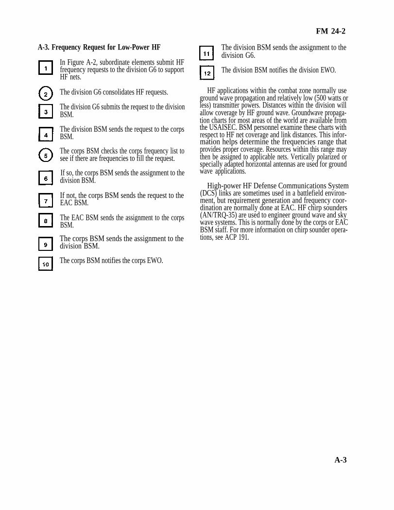
A-3. Frequency Request for Low-Power HF
In Figure A-2, subordinate elements submit HFfrequency requests to the division G6 to supportHF nets.
The division G6 consolidates HF requests.
The division G6 submits the request to the divisionBSM.
The division BSM sends the request to the corpsBSM.
The corps BSM checks the corps frequency list tosee if there are frequencies to fill the request.
If so, the corps BSM sends the assignment to thedivision BSM.
If not, the corps BSM sends the request to theEAC BSM.
The EAC BSM sends the assignment to the corpsBSM.
The corps BSM sends the assignment to thedivision BSM.
The corps BSM notifies the corps EWO.
FM 24-2
The division BSM sends the assignment to thedivision G6.
The division BSM notifies the division EWO.
HF applications within the combat zone normally useground wave propagation and relatively low (500 watts orless) transmitter powers. Distances within the division willallow coverage by HF ground wave. Groundwave propaga-tion charts for most areas of the world are available fromthe USAISEC. BSM personnel examine these charts withrespect to HF net coverage and link distances. This infor-mation helps determine the frequencies range thatprovides proper coverage. Resources within this range maythen be assigned to applicable nets. Vertically polarized orspecially adapted horizontal antennas are used for groundwave applications.
High-power HF Defense Communications System(DCS) links are sometimes used in a battlefield environ-ment, but requirement generation and frequency coor-dination are normally done at EAC. HF chirp sounders(AN/TRQ-35) are used to engineer ground wave and skywave systems. This is normally done by the corps or EACBSM staff. For more information on chirp sounder opera-tions, see ACP 191.
A-3

FM 24-2
A - 4

A-4. Frequency Request for VHF-FM
In Figure A-3, the division G6 submits the re-quest to the division BSM for VHF-FM frequen-cies to support the SOI.
The division BSM submits the request to the corpsBSM.
The corps BSM sends the request to the EACBSM.
The EAC BSM sends the assignment to the corpsBSM.
The corps BSM notifies the corps EWO.
The corps BSM sends the assignment to thedivision BSM.
The division BSM notifies the division EWO.
FM 24-2
The division BSM sends the assignment to thedivision G6.
The division G6 makes up the VHF-FM list andsubmits it to the SOI Detachment/NSA for theVHF-FM portion of the SOI.
VHF-FM spectrum resources support combat net radiooperations and MSE. Since the direction and coordinationof real-time combat operations requires that everybattlefield element be equipped with combat net radios,this frequency band is quite crowded. Corps combat netradio net requirements exceed spectrum availability fordedicated frequencies to support every net. Frequenciesare reused or shared many times in the corps area. Thissharing scheme is a major consideration of the BSM staff,and it is used as the basis for estimating requirements.
The frequency range of VHF-FM combat net radioequipment is 30 to 88 MHz. It has output powers rangingup to 50 watts depending on the transmitter used.
A-5
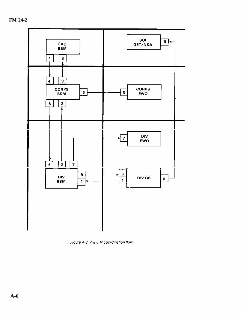
FM 24-2
A-6

FM 24-2
A-5. Frequency Request for Platoon EarlyWarning Sensors
In Figure A-4, the division G6 determines thenumber of platoon early warning sensors (PEWS)based on TOE, TDA, or MTOE operational re-quirements.
The division G6 submits the request to the divisionBSM.
The division BSM sends the request to the corpsBSM.
The corps BSM sends the request to the EACBSM.
The corps BSM sends the allotment to the divisionBSM.
The division BSM sends the allotment to thedivision G6.
The division G6 sends the allotment to themaneuver battalions operating the PEWS.
PEWS are lightweight, battery-operated, portableintrusion detection devices. Small military units (patrols,squads, or platoons) use these devices. On detection, thedevice electronically classifies the intruder (personnel orvehicle) and communicates the detection and target typeto a remote receiver display by a radio link. Severaldifferent sensor models are available. Each model operateson a fixed frequency in the 138 to 153 MHz range.
The EAC BSM sends the allotment to the corpsBSM.
A-7

FM 24-2
A-8

FM 24-2
A-6. Frequency Request for VHF-AM
In Figure A-5, the division G6 submits the requestto the division BSM for VHF-AM frequencies tosupport division aviation and air traffic controlnets in the SOI.
The division BSM sends the request to the corpsBSM.
The corps BSM sends the request to the EACBSM.
The EAC BSM sends the assignment to the corpsBSM.
The corps BSM notifies the corps EWO.
The corps BSM notifies the corps aviation officer.
The corps BSM sends the assignment to thedivision BSM.
The division BSM notifies the division EWO.
The division BSM notifies the division aviationofficer.
The division BSM sends the assignment to thedivision G6.
The division G6 makes up the VHF-AM frequen-cy list and submits it to the SOI Detachment/NSAfor VHF-AM portion of the SOI.
The VHF-AM frequency band for military applicationsis 118 to 150 MHz. Small segments are allocated forexclusive military use in some countries, but most of thisband is allocated to the aeronautical mobile R service. TheR denotes route which implies that the band is used forcommunications with aircraft flying established air routes.Most governments consider R bands for communicatingwith civil aircraft. (Bands designated OR, for off-route, aregenerally limited to military use.) The R band frequencyresources are normally controlled by the civil aviationauthority in each country (FAA in the US).
Although Army air traffic control and aviationoperations are usually conducted on VHF-FM orUHF-AM frequencies, a requirement exists for VHF-AM.Civil aircraft sometimes need to contact Army air trafficcontrol facilities, and occasionally military aircraft areequipped with only VHF-AM radios. Additionally,VHF-AM provides a degree of redundance shouldVHF-FM or UHF-AM systems fail.
A-9

FM 24-2
A-10
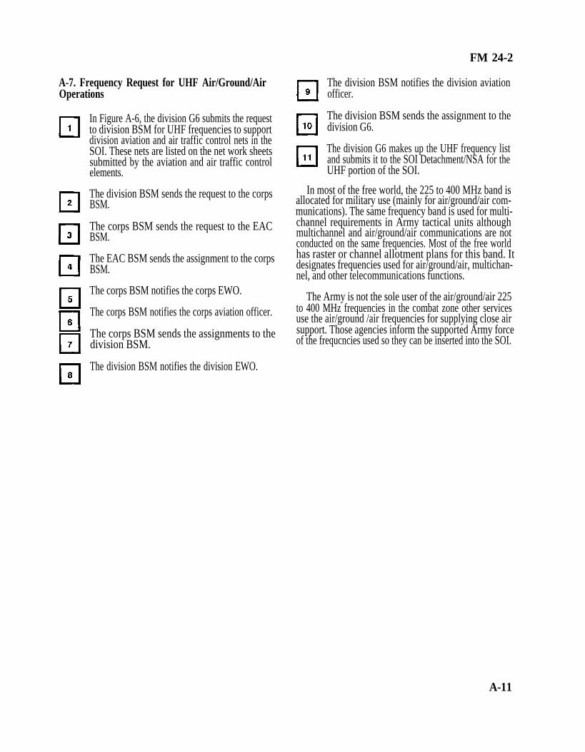
FM 24-2
A-7. Frequency Request for UHF Air/Ground/AirOperations
In Figure A-6, the division G6 submits the requestto division BSM for UHF frequencies to supportdivision aviation and air traffic control nets in theSOI. These nets are listed on the net work sheetssubmitted by the aviation and air traffic controlelements.
The division BSM sends the request to the corpsBSM.
The corps BSM sends the request to the EACBSM.
The EAC BSM sends the assignment to the corpsBSM.
The corps BSM notifies the corps EWO.
The corps BSM notifies the corps aviation officer.
The corps BSM sends the assignments to thedivision BSM.
The division BSM notifies the division EWO.
The division BSM notifies the division aviationofficer.
The division BSM sends the assignment to thedivision G6.
The division G6 makes up the UHF frequency listand submits it to the SOI Detachment/NSA for theUHF portion of the SOI.
In most of the free world, the 225 to 400 MHz band isallocated for military use (mainly for air/ground/air com-munications). The same frequency band is used for multi-channel requirements in Army tactical units althoughmultichannel and air/ground/air communications are notconducted on the same frequencies. Most of the free worldhas raster or channel allotment plans for this band. Itdesignates frequencies used for air/ground/air, multichan-nel, and other telecommunications functions.
The Army is not the sole user of the air/ground/air 225to 400 MHz frequencies in the combat zone other servicesuse the air/ground /air frequencies for supplying close airsupport. Those agencies inform the supported Army forceof the frequcncies used so they can be inserted into the SOI.
A-11

FM 24-2
A-12

A-8. Frequency Request for Division MSE LOSSystems
In Figure A-7, the division signal battalion deter-mines how many frequencies are required to sup-port the division multichannel plan.
The signal battalion requests frequencies from thedivision BSM.
The division BSM checks the request for accuracyand validity.
If the division BSM does not have authority to allotmultichannel frequencies, then the request is for-warded to the corps BSM.
The corps BSM allots frequencies to the divisionBSM.
The corps BSM notifies the corps EWO of theallotment.
The division BSM receives the allotment andnotifies the division EWO.
The division BSM sends allotment to the signalbattalion.
The signal battalion assigns frequencies as re-quired to engineered systems.
FM 24-2
In MSE LOS systems, the number of channels per linkranges from 8 to 64. The high capacity of MSE systemsallows them to meet large volume demands for commandand control, fire control, intelligence, and administrativetraffic.
For MSE LOS purposes, the frequency spectrum isseparated into three bands. Two are UHF, band 1, 225 to400 MHz and band 3, 1350 to 1850 MHz support theinternodal extension link, using the AN/GRC-226 radio.To support the shorter SHF down-the-hill (DTH) link, theAN/GRC-224(P) radio uses SHF band 2, 14.5 to 15.35GHz.
Antennas used in multichannel systems are highly direc-tional. For this reason, relatively low powers (15 to 35watts) are the rule. In comparison, troposcatter systemstypically use 1 kilowatt of power because of the high signalattenuation in the troposphere.
It is common to have transmitter and receiver antennasin close proximity. Also, two or more multichannel linksmay terminate at the same site. For these reasons, frequen-cy separation between transmit and receive frequencies ofthe same link and frequency separation between differentlinks are critical. Separation criteria vary with the type ofequipment used.
The MSE links take some time to establish. MSE LOSfrequencies are not included in the SOI frequency chang-ing program. With each frequency change, the LOS linkhas to be reestablished. The time involved in the operationmakes the MSE LOS system a poor candidate for a peri-odic frequency changing program.
A-13

FM 24-2
A-9. Frequency Request for Corps MSE LOS The corps BSMment. Systems
In Figure A-8, the corps signal brigade radio of-ficer determines how many frequencies are re-quired to support the corps MSE LOS systems.
The signal brigade requests frequencies from thecorps BSM.
The corps BSM requests frequencies from theEAC BSM.
The EAC BSM allots frequencies to the corpsBSM.
The corps BSMbrigade.
notifies the corps EWO of allot-
sends the allotment to the signal
The corps signal brigade assigns the frequenciesto engineered systems as required.
The corps BSM normally has an allotment offrequencies available which satisfy multichannel spectrumrequirements for corps and subordinate units. TheSpectrum Management Office of the TSC(A) overseas andthe post, camp, station in CONUS provide this allotment.
A-14

FM 24-2
A-10. Frequency Request for MeteorologicalSondes
In Figure A-9, the corps artillery officer deter-mines the number of meteorological units withinthe corps area of operation.
The artillery officer sends a request for frequencysupport to the corps BSM.
The corps BSM sends the request to the EACBSM.
The EAC BSM sends the allotment to the corpsBSM.
The corps BSM sends the allotment to the corpsartillery officer.
The corps artillery officer gives the authorizationto the units operating the equipment.
Meteorological sondes (METSONDES) areballoon-borne equipments which measure atmosphericpressure, temperature, humidity, wind speed, and winddirection in the atmosphere. This data is used primarily tosupport artillery operations within the corps area.
The US Army presently uses METSONDES whichoperate in the 1660 to 1700 MHz range. Atmosphericsoundings are taken at various altitudes and the data istransmitted to a ground tracking station which receives,records, processes, and disseminates the information tousers.
A-15

FM 24-2
A-11. Frequency Request for Ground MobileForces Satellite (7 to 8 GHz)
In Figure A-10, the division G3 and division G6develop requirements for satellite communica-tions.
The division G6 sends the satellite access requestto the division BSM.
The division BSM checks the request for accuracyand validity.
The division BSM sends the request to corpsBSM.
The corps BSM sends the satellite access requestto the EAC BSM.
The EAC BSM sends the request to the groundmobile forces (GMF) satellite communicationcontrol subsystem (SCCS) manager for the
The GMF manager sends the up link and downlinkfrequencies and other pertinent information tothe EAC BSM for clearance/approval and dis-semination.
The EAC BSM sends the assignment to the corpsBSM.
The corps BSM coordinates the assignment withthe corps EWO.
The corps BSM sends the assignment to thedivision BSM.
The division BSM coordinates the assignmentwith the division EWO.
The division BSM sends the assignment to thedivision G6 for distribution to the ground forcessatellite operators.
defense communications area.
A-16

FM 24-2
The SHF transportable GMF terminals providemultichannel communications at brigade, division, corps,and the COMMZ to support command multichannelrequirements. The terminals operate with DefenseSatellite Communications System (DSCS) satellitespositioned in geosynchronous orbit over the equator abovethe Pacific, Atlantic, and Indian Oceans. Figure A-11shows the SHF and UHF satellites and terminals.
Procedures for obtaining GMF satellite terminalauthorizations are unique in that two separate and distinctapprovals must be obtained before starting operations. TheGMF manager grants an approved uplink and downlinkfrequency; however, these frequencies must be clearedthrough normal frequency management channels. Thecorps BSM ensures that frequency and satellite accessapproval has been received before notifying subordinateelements. See FM 24-11 for further information.
A-17

FM 24-2
A-12. Frequency Request for UHF Single-ChannelSatellite Terminal
In Figure A-12, the division G3 and division G6develop the requirements for using a single-chan-nel satellite net.
The division G6 sends the request to the divisionBSM.
The division BSM sends the request for channelaccess to the corps BSM.
The corps BSM sends the request to the EACBSM for channel access and frequency approval.
The EAC BSM sends the request for channelaccess to the appropriate satellite primary controlcenter (PCC).
The satellite PCC sends the uplink and downlinkfrequencies and any other pertinent informationto the EAC BSM for approval and dissemination.
The EAC BSM sends the approved uplink anddownlink frequencies to the corps BSM.
The corps BSM coordinates the assignment withthe corps EWO.
The corps BSM sends the assignment to thedivision BSM.
The division BSM coordinates the assignmentwith the division EWO.
A-18

FM 24-2
The division BSM sends the assignment to thedivision G6.
The division G6 sends the assignment to the sup-ported units.
The UHF single-channel satellite service shares the 225to 400 MHz band with air/ground and multichannel ser-vices, among others. While multichannel and air/groundallotted channels occasionally share a channel with anotherservice, it is rare that a channel designated for single-chan-nel satellite has an allotment for any other service.
Most single-channel satellite terminals have thecapability of a single voice channel. Some of the newer
terminals have a speech plus capability, that is, one voicechannel plus one teletype (low speed) channel. Normally,only high-priority command and control circuits are routedover single-channel satellite facilities.
Like multichannel satellite terminals, two distinctseparate approvals must be obtained. First, the PCCprovides the satellite access uplink and downlink frequen-cies; however, these frequencies must be cleared throughnormal frequency management channels. Requests forsatellite access are sent to the PCC which controls thesatellite in the desired area of operations. In CONUS,corps or division spectrum managers can request satelliteaccess from the appropriate PCC. In Europe, it is almostalways an EAC spectrum manager function to 5th SignalCommand. See FM 24-11 for further information.
A-19

FM 24-2
A-13. Frequency Request for Air Traffic ControlRadar
In Figure A-13, the air traffic control officer deter-mines the location of the air traffic control radar.
The air traffic control officer requests frequenciesfor radar and IFF from the division BSM.
The division BSM sends the request to the corpsBSM.
The corps BSM sends the request to the EACBSM.
The EAC BSM sends the assignment to the corpsBSM.
The corps BSM sends the assignment to thedivision BSM.
The corps BSM notifies the corps EWO.
The division BSM sends the assignment to the airtraffic control officer.
The division BSM notifies the division EWO.
A-20

FM 24-2
The air traffic control officer notifies the divisionaviation officer and division BSM when radar andIFF are checked and operational.
Air traffic control radar provides radar approachcontrol and precision approach radar for aircraft duringadverse weather conditions and high density aircraftoperations. The AN/TPN-18 is used for primary radar andthe AN/TPX-44 is used for secondary or IFF radar. Thetwo equipments work together. Primary and IFF returnsare adjacently displayed on the same scope. The two
equipments are normally integral parts of an AN/TSQ-71Alanding control central configuration. The AN/TPN-18operates in the 9.0 to 9.6 GHz band while the AN/TPX-44operates in the 990 to 1040 MHz band.
Within CONUS, short-term frequency assignments cansometimes be obtained from the supporting Armyfrequency coordinator’s office, thus avoidingtime-consuming frequency clearance procedures at thenational agency level.
A-21

FM 24-2
A-14. Frequency Request for Forward Area AlertingRadar
In Figure A-14, the air defense artillery sends therequest for frequency support (maximum of sixchannels) of forward area alerting radar to thedivision G6.
The division G6 sends the request to the divisionBSM.
The division BSM sends the request to the corpsBSM.
The corps BSM sends the request to the EACBSM.
The EAC BSM sends the assignment to the corpsBSM.
The corps BSM notifies the corps EWO.
The corps BSM sends the assignment to thedivision BSM.
The division BSM notifies the division EWO.
The division BSM sends the assignment to thedivision G6.
The division G6 sends the assignment to the airdefense artillery battalion.
The air defense artillery battalion assigns chan-nels to individual radars according to the SOP.
The forward area alerting radar system consists of anacquisition radar, an IFF for initial identification, and anRF data link to transmit data to a target alert data displayset to support SHORAD weapons (for example,CHAPARRAL, VULCAN, and REDEYE). TheAN/TPQ-32 or AN/MPQ-49 is used when equipment isvehicle mounted (tuning range is classified). The airdefense artillery battalion requests frequencies for theradar and IFF from the division BSM. Frequencies tosupport the data links are found in the division SOI.
A-22

FM 24-2
A-23

FM 24-2
A-15. Frequency Request for VULCAN Radar(AN/VPS-2)
In Figure A-15, the air defense artillery battalionsends a request for frequencies and a pulse repeti-tion frequency (PRF) to support CHAPAR-RAL/VULCAN operations to the division G6.
B S M .The division G6 sends the request to the division
The division BSM sends the request to corpsBSM.
The corps BSM sends the request to the EACBSM.
The range-only-radar, AN/VPS-2, is part of the VUL-
The EAC BSM sends the assignment to the corpsBSM.
The corps BSM notifies the corps EWO.
The corps BSMdivision BSM.
The division BSM
sends the assignment to the
notifies the division EWO.
The division BSM sends the assignment to thedivision G6.
The division G6 sends the assignment to the airdefense artillery battalion.
The air defense artillery assigns frequencies toindividual radars.
CAN air defense system and is used in the fire controlsystem for antiaircraft artillery guns against low-flying sub-sonic tactical aircraft. The radar can track aircraft movingat range rates between 10 and 310 meters per second to amaximum range of 5,000 meters. The radar operates in the9150 to 9250 MHz range with a peak power of 1.5 kilowatts.The entire tuning range is allotted.
A-24

FM 24-2
A-25

FM 24-2
A-16. Frequency Request for Moving TargetLocating Radar
A-26
In Figure A-16, the requirement for moving targetlocating radar is developed at the CEWI battalionand the target acquisition battery.
The CEWI battalion and target acquisition bat-tery send the frequency request to the divisionBSM.
The division BSM sends the request to the corpsBSM.
The corps BSM sends the request to the EACBSM.
The EAC BSM sends the allotment to the corpsBSM.
The corps BSM sends the allotment to the divisionBSM.
The division BSM sends the allotment to theCEWI battalion and the target acquisition battery.
The CEWI battalion and target acquisition bat-tery send the allotment to the ground surveillanceradar (GSR) platoon and GSR section.
The ground surveillance company of the division CEWIbattalion and the target acquisition battery operate themoving target locating radar.
The moving target locating radar is deployed near theFLOT and detects moving targets (vehicles andpersonnel). Equipments used are the AN/TPS-25 andAN/TPS-58. Frequencies are allotted for the frequencyrange of the equipment (9400 to 9600 MHz).

FM 24-2
A-27

FM 24-2
A-17. Frequency Request for Counter Mortar andCounter Battery
A-28
In Figure A-17, the requirement at division forcounter mortar and counter battery is based onTOE and MTOE allowances on hand or plannedto be on hand. Requests for frequency support aresent to the division G6 by the target acquisitionbattery for counter mortar and counter battery.Equipments used are the AN/TPQ-36, AN/TPQ-37, and AN/MPQ-4.
Requests for frequency support are received bythe division BSM and checked for validity andaccuracy. The division artillery signal officer iden-tifies requirements to the division BSM. (Thisincludes cross attached corps artillery assets con-trolled by division artillery.)
The division BSM sends the request to the corpsBSM.
The corps BSM sends the request to EAC BSM.
The EAC BSM sends the frequency assignmentsto the corps BSM.
The corps BSM notifies the corps EWO.
The corps BSM sends the assignments to thedivision BSM.
The division BSM sends the assignments to therequesting elements.
The division BSM notifies the division EWO.
Counter mortar and counter battery radars are usuallylocated along the FLOT looking toward the enemy. Theradar locates cannons, mortars, and rockets by detectingthe position of the in-flight projectile at two points in spaceand extrapolating this trajectory to its point of origin. Theradar is usually turned off when enemy mortar and artilleryfire is not occurring to reduce its vulnerability to directionfinding. Frequencies are normally allotted for the frequen-cy range of the radar.

FM 24-2
A-29

FM 24-2
A-18. Frequency Request for GSR
battalion.
In Figure A-18, the requirements for GSR aredeveloped by division/corps G2 and the CEWI
The division/corps CEWI battalion sends the fre-quency request to the division/corps BSM.
The division BSM sends the request to the corpsBSM.
The corps BSM sends the request to the EACBSM.
The EAC BSM sends the allotment to the corpsBSM.
The corps BSM sends the allotment to the corpsCEWI battalion.
The corps BSM sends the allotment to the divisionBSM.
The division BSM sends the allotment to thedivision CEWI battalion.
The CEWI battalion sends the allotment to theGSR platoons.
GSR is operated at division level by the division CEWIbattalion. At corps and separate brigades, the militaryintelligence group provides support. Frequencies are al-lotted for the entire tuning range.
A-30

FM 24-2
A-19. Frequency Request for SINCGARS (VHF-FMFH)
In Figure A-19, the division G6 submits thedivision FH net list to the division BSM for VHF-FM frequencies to support the division combatnet radio FH nets.
The division BSM submits the request to the corpsBSM.
The corps BSM sends the request to the EACBSM.
The EAC BSM sends the assignments and lockoutinformation the corps BSM.
The corps BSM coordinates frequency assign-ment information with the corps EWO.
The corps BSM sends frequency assignments, fre-quency lockouts, and net IDs to the division BSMby fill device/disk, if applicable.
The division BSM coordinates frequency assign-ment information with the division EWO.
The division BSM sends frequency assignments,frequency lockouts, and net IDs to the division G6.
The division G6 performs SINCGARS SOIgeneration and distributes the SOI to all subor-dinate units by fill device/disk.
VHF-FM spectrum resources (30 to 88 MHz) alongwith the decentralized automated support system (BECS)is required to support effective SINCGARS operation onthe battlefield. The BECS generates, manipulates, prints,stores, displays, and transfers the information required tooperate the SINCGARS in the FH/SINGLE-CHANNELmode. A hopset is a given number of frequencies which theSINCGARS can hop or transmit. A hopset can be anynumber of frequencies from 1 to 2320. As with single-chan-nel radio operation, certain civilian radio services continueto be factors in obtaining and distributing frequencyresources. Frequencies used for these services continue tobe protected from interference by SINCGARS.
A-31

FM 24-2
A-20. Request for ECM Jamming Authorization The corps BSM sends the request to the EAC.
In Figure A-20, the CEWI battalion develops theECM plan to include the list of frequencies to bejammed and the point of contact information.
The CEWI battalion sends the request to thedivision BSM.
The division BSM sends the request to the corpsBSM.
BSM.
The EAC BSM sends the authorization for jam-ming, frequencies cleared for jamming, and anyrestrictions to the corps BSM.
The corps BSM sends the authorization to thedivision BSM.
The division BSM sends authorization to the CEWI battalion.
A-32

FM 24-2
A-33

FM 24-2
A-21. MIJI - Part I. Meaconing, Intrusion, andJamming
A-34
In Figure A-21, the operator detects abnormaloperation of the receiving equipment.
The operator checks the equipment to ensure thatthe abnormal operation is not being caused by anequipment malfunction.
The operator checks with adjacent units to deter-mine if that is the source of the problem.
If the operator determines that the abnormaloperation is caused by an outside source, theoperator initiates a MIJI report and sends it to theBSM.
The division BSM and division EWO evaluate theMIJI report to determine whether the problem iscaused by friendly or unfriendly sources. Thecorps BSM and EWO and the EAC BSM andEWO may also evaluate the report depending onwhat level the report is initiated.
If the source is determined to be unfriendly, theEWO will attempt to locate it, identify it, and ifdetermined to be a serious threat, target it fordestruction or neutralize its effect.
The BSM, with command guidance and in coor-dination with the EWO, will require the equip-ment to continue operating to conceal that MIJ isaffecting its operation. The BSM may assign alter-nate frequencies to allow the affected unit tooperate a second piece of equipment so the mis-sion can continue.
If the source cannot be determined, a follow-upMIJI report is sent with all available informationto the JEWC and other addressees as required.
The JEWC will enter the information into the database and attempt to determine the source of theproblem.
The JEWC notifies the reporting unit and otheraddressees of its findings.
The appropriate units take any remaining resolu-tion actions.

FM 24-2
A-35

FM 24-2
A-22. MIJI - Part II. Interference
In Figure A-22, the operator detects abnormaloperation of the receiving equipment.
The operator checks the equipment to ensure thatthe abnormal operation is not being caused by anequipment malfunction.
The operator (or the NCOIC, OIC, or signal of-ficer) checks with adjacent units to determine ifthat is the source of the problem.
If the operator determines that the abnormaloperation is caused by an outside source, theoperator initiates a MIJI report and sends it to theBSM.
The division BSM and division CEWI evaluate thereport to determine whether the problem iscaused by friendly or unfriendly forces. The corpsBSM and CEWI and the EAC BSM and EWOmay also evaluate the report as required.
If the source is friendly and it can be found, theproblem can be resolved locally or through liaisonwith the source unit.
If the source cannot be determined, a follow-upMIJI report is sent with all available informationto the JEWC and other addressees as required.
The JEWC will enter the information into the database and attempt to determine the source of theproblem.
The JEWC notifies the reporting unit (and otheraddressees) of the findings.
The reporting unit takes the necessary action toeliminate or mitigate the problem. The unit mayhave to request technical assistance.
A-36

FM 24-2
A-37
FM 24-2
Appendix B
Interference Charts
B-1. Description and Use
The interference charts in this appendix can be used indetermining the distance separation required forcochannel and adjacent channel operation. Distanceseparation charts indicate the spacing needed betweenstations under different conditions of transmitter poweroutput and types of emission. Interfering equipment isreferred to as the undesired transmitter. Equipmentinterfered with is called the receiver and desiredtransmitter.
The following services are covered by the charts: AMSSB voice, teletype, and FM voice/data. Two charts areshown for each type of service. One chart is for use whenthe desired and undesired transmitters are on the samefrequency; the other chart is used when the undesiredtransmitter is on an adjacent channel separated by thefrequency indicated.
B-2. Sample Problem
Problem.
A desired transmitter and the desired receiver areoperating an FM voice net on low power (8 watts) located3 miles apart. What is the minimum distance a high power(35 watts) FM transmitter operating on the same frequencycan be placed from the desired receiver without causinginterference?
Solution.
Since the desired signal is FM voice, the desiredtransmitter and receiver are operating on low power. Theundesired transmitter is operating on high power and allare on the same frequency (Figure B-1).
The ratio of the undesired transmitter power to thedesired transmitter power is 35 to 8 (about 4 to 1).
Enter the chart on the horizontal scale at the 3-milepoint and extend a vertical line from this point until it meetsthe curve corresponding to a ratio of 4 to 1.
The curve corresponding to a ratio of 4 to 1 is not shownon the chart, but its position is found by interpolatingbetween the 1 to 1 and 10 to 1 curves.
From this point, a horizontal line is drawn to the left untilit intersects the vertical scale which indicates a distance of6 miles.
Therefore, the minimum distance that the 35-wattundesired transmitter must be separated from the receiveris 6 miles.
NOTE: Interpolation is logarithmic between curvesand gridlines.
B-3. Special Considerations
The adjacent channel charts are for 5-kHz separation(using 11 MHz frequency for SSB-voice AM equipment)and 50-kHz separation (using 53 MHz frequency for FMequipment). Any interfering equipment with less channelseparation from the receiver than indicated in these chartsresults in a greater required distance separation from thedesired receiver, and should be sited using thesame-channel charts.
Figures B-1 and B-2 are charts for FM equipment basedon the characteristics of the AN/VRC-12 series radio.These charts apply to equipment having similarcharacteristics as to maximum frequency deviation,selectivity, and frequency stability. Figures B-3 and B-4 areinterference charts for SINCGARS versus SINCGARS.Figures B-5 through B-12 are interference charts forSINCGARS versus AN/VRC-12 series radio. Figure B-13is an interference chart for AN/PRC-77 versusSINCGARS. Figures B-14 through B-17 are charts for SSBequipment based on the characteristics of theAN/GRC-106 radio set. These charts apply to equipmenthaving similar characteristics as to modulation, selectivity,and frequency stability.
Only ground wave and direct wave transmissions wereconsidered in preparing these charts. Propagation over asmooth spherical earth and using 15-foot vertical whipantennas were considered, based on cochannelsignal-to-interference thresholds of AN/VRC-12, 6 dB;AN/GRC-106, SSB, 4 dB; and AN/GRC-106, teletype, 9dB.
B-1

FM 24-2
Mutual interference problems often result when FM the AN/PRC-25, AN/PRC-77, and the vehicular versionstransmitters operating on different frequencies are of these radios. These interference problems can besituated in the same locale. The problem can occur effectively reduced when the following basic assignmentbetween AN/VRC-12 series radios and also between these standards are followed.radios and low power FM radios. These radio sets include
B-2

FM 24-2
B-3
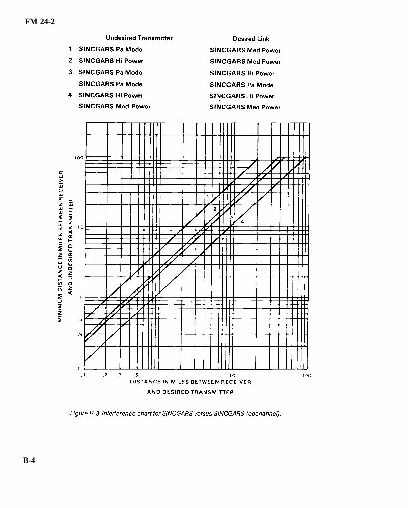
FM 24-2
B-4

FM 24-2
B-5

FM 24-2
B-6

FM 24-2
B-7

FM 24-2
B - 8

FM 24-2
B-9

FM 24-2
B-10

FM 24-2
B-11

FM 24-2
B-12

FM 24-2
B-13

FM 24-2
B-14

FM 24-2
B-15

FM 24-2
B-16

FM 24-2
B-17

FM 24-2
B-18

FM 24-2
B-19

FM 24-2
When using the AN/VRC-12 series radio, avoid usingfrequencies that are harmonically related. For example,frequencies that are separated by exactly 5.75 or 23.00MHz.
Do not assign frequencies to collocated nets that are onthe order of the second harmonic. For example, thefrequency setting of 30.00, 32.65, and 35.00 MHz willpossibly interfere with a radio using 60.00,65.30, and 70.00MHz, respectively.
Observe the recommended minimum frequency versusdistance restrictions given in Table B-1.
B-20
High frequency AM nets experience fewer interferenceproblems than VHF, FM nets; however, some interferencemay result when these radios are operated in the samevicinity. Therefore, collocated HF nets should be assignedfrequencies at least 100 kHz apart. RATT nets operatingin the FULL-DUPLEX mode, with the transmitter andreceiver on different frequencies, require a frequencyseparation of at least 400 kHz.

FM 24-2
8-21

FM 24-2
Appendix C
Procedure for Field Level Selection andCoordination of RF Use
C-1. FAA Coordinators
FAA coordinators and geographical areas ofresponsibility for the frequency 1030 MHz and the bands1215 to 1400 MHz, 2700 to 2900 MHz, and 9000 to 9200MHz are shown below. (See Figure C-l).
Northwest Mountain Region
Spectrum Management Officer, ANM-464Federal Aviation Administration17900 Pacific Highway South C-68966Seattle, Washington 98168Telephone: 206-431 -2407/2473/2503/2464Colorado; Idaho; Montana; Oregon; Utah;Washington; Wyoming.
Western Pacific Region
Spectrum Management Officer, AWP-406Federal Aviation AdministrationP.0. BOX 92007Los Angeles, California 90009Telephone: 213-297- 1165/1685/1342/1164/
1872/0214/0510/0276Arizona; Californiaj including all offshore islands;
Nevada.
Central Region
Spectrum Management Officer, ACE-433Federal Aviation Administration601 12th StreetKansas City, Missouri 64106Telephone: 816-426-5036/5647Iowa; Kansas; Missouri; Nebraska.
Southwest Region
Spectrum Management Officer, ASW-465Federal Aviation AdministrationFort Worth, Texas 76193-0465Telephone: 817-624-5466/5465/5458/5467/5469Arkansas; Louisiana; New Mexico; Oklahoma; Texas.
Great Lakes Region
Spectrum Management Officer, AGL-423Federal Aviation Administration2300 East Devon AvenueDes Plaines, Illinois 60018Telephone: 312-694-7332/7363/7616/7842/7071Illinois; Indiana; Michigan; Minnesota; North Dakota;
South Dakota; Ohio; Wisconsin.
Southern Region
Spectrum Management Officer, ASO-465Federal Aviation AdministrationP.O. BOX 20636Atlanta, Georgia 30320Telephone: 404-763-7385/7386Alabama; Florida; Georgia; Kentucky; Mississippi;
North Carolina; Puerto Rico; South Carolina;Tennessee; US Possessions in the Caribbean; VirginIslands.
Eastern Region
Spectrum Management Officer, AEA-435Federal Aviation AdministrationFitzgerald Federal BuildingJFK International AirportJamaica, New York 11430Telephone: 718-917-1191Delaware; District of’ Columbia; Maryland; New Jersey;New York; Pennsylvania; Virginia; West Virginia.
New England Region
Spectrum Management Officer, ANE-461Federal Aviation Administration12 New England Executive ParkBurlington, Massachusetts 01803Telephone: 617-273-7160/2408/7197Connecticut; Maine; Massachusetts; New Hampshire;Rhode Island; Vermont.
C-1

FM 24-2
Alaskan Region Western Pacific Hawaii Region
Spectrum Management Officer, AAL-464BFederal Aviation Administration701 C Street, P.O. BOX 14Anchorage, Alaska 99513-0087Telephone: 907-271-5343Alaska.
Spectrum Management Officer, AWP-406HFederal Aviation AdministrationDiamond Head SFO4204 Diamond Head RoadHonolulu, Hawaii 96816-4420Telephone: 808-734-6627Hawaii; US Possessions in the Pacific Ocean.
C-2

FM 24-2
Table C-1 shows the designated heavily used areas inthe 2700 to 2900 MHz band. Figure C-2 is a geographicpresentation of these areas.
C-3

FM 24-2
C-4
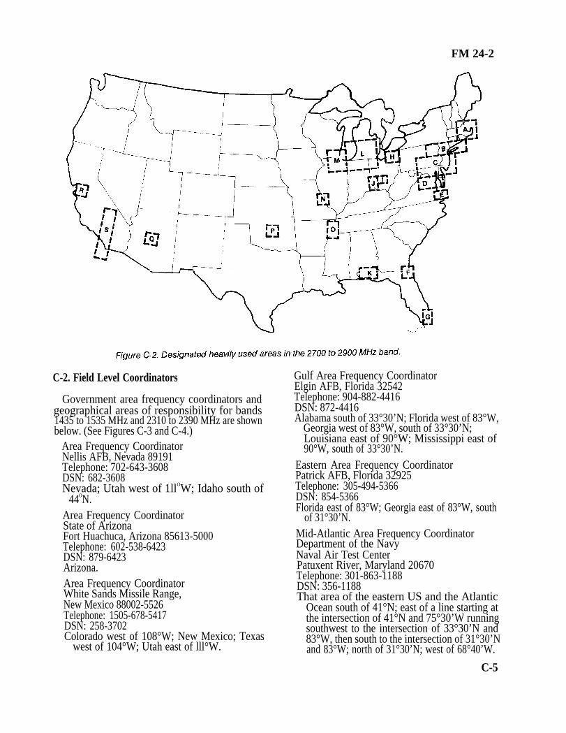
FM 24-2
C-2. Field Level Coordinators
Government area frequency coordinators andgeographical areas of responsibility for bands1435 to 1535 MHz and 2310 to 2390 MHz are shownbelow. (See Figures C-3 and C-4.)
Area Frequency CoordinatorNellis AFB, Nevada 89191Telephone: 702-643-3608DSN: 682-3608Nevada; Utah west of 1llOW; Idaho south of
44ON.Area Frequency CoordinatorState of ArizonaFort Huachuca, Arizona 85613-5000Telephone: 602-538-6423DSN: 879-6423Arizona.Area Frequency CoordinatorWhite Sands Missile Range,New Mexico 88002-5526Telephone: 1505-678-5417DSN: 258-3702Colorado west of 108°W; New Mexico; Texas
west of 104°W; Utah east of lll°W.
Gulf Area Frequency CoordinatorElgin AFB, Florida 32542Telephone: 904-882-4416DSN: 872-4416Alabama south of 33°30’N; Florida west of 83°W,
Georgia west of 83°W, south of 33°30’N;Louisiana east of 90°W; Mississippi east of90°W, south of 33°30’N.
Eastern Area Frequency CoordinatorPatrick AFB, Florida 32925Telephone: 305-494-5366DSN: 854-5366Florida east of 83°W; Georgia east of 83°W, south
of 31°30’N.Mid-Atlantic Area Frequency CoordinatorDepartment of the NavyNaval Air Test CenterPatuxent River, Maryland 20670Telephone: 301-863-1188DSN: 356-1188That area of the eastern US and the Atlantic
Ocean south of 41°N; east of a line starting atthe intersection of 41°N and 75°30’W runningsouthwest to the intersection of 33°30’N and83°W, then south to the intersection of 31°30’Nand 83°W; north of 31°30’N; west of 68°40’W.
C-5

FM 24-2
Army Frequency CoordinatorMilitary District of WashingtonMilitary District of Washington, DC 20319-5050Telephone: 202-693-5154DSN: 223-5154District of Columbia; county of Arlington (less
Fort Belvoir but including Davison AAF) andthe city of Alexandria in the state of Virginia;counties of Montgomery and Prince Georgesin the state of Maryland.
CommanderUSAISC - AlaskaATTN: CCNA-AK-CEFort Richardson, Alaska 99505Telephone: 317-862-6294DSN: 863-6294Alaska.CommanderUS Army PacificATTN: APCEFort Shafter, Hawaii 96858Telephone: 808-438-2261Hawaii.
Area Frequency Coordinator (Air Force)Headquarters Alaskan Air Command/DCTElmendorf AFB, Alaska 99506Telephone: 907-752-2283DSN: 317-752-2283Alaska; established DOD area frequency
coordinator for all frequency use within thestate of Alaska.
Area Frequency CoordinatorDepartment of the Air ForceUSAF Frequency Management CenterWashington, DC 20330-6431Telephone: 202-475-1825DSN: 335-1825Alabama north of 33°30’N: Connecticut:
Kentucky; Maine; Massachusetts; Mississippiless east of 90°W, south of 33°30’N; NewHampshire; New Jersey north of 41°N; NewYork north of 41°N; Ohio; Rhode Island;Tennessee; Vermont; West Virginia; and thoseareas of the following states west of theMid-Atlantic AFC area: Georgia north of33°30’N; Maryland; North Carolina;Pennsylvania including that north of 41°N;South Carolina; Virginia.
C-6

FM 24-2
Army Frequency Management OfficeContinental United StatesATTN: SFIS-FAC-SCFort Sam Houston, Texas 78234-5000Telephone: 512-221-7050/2820DSN: 471-7050/2820Alabama, Arkansas, California (less units
located on or conducting training of the ArmyNational Training Center, Fort Irwin, CA),Colorado, (less the area west of 108°W),Connecticut, Delaware, Florida, Georgia,Idaho, Illinois, Indiana, Iowa, Kansas,Kentucky, Louisiana, Maine, Maryland (lesscertain areas which are included in theMilitary District of Washington),Massachusetts, Michigan, Minnesota,Mississippi, Missouri, Montana, Nebraska,Nevada, New Hampshire, New Jersey, NewYork, North Carolina, North Dakota, Ohio,Oklahoma, Oregon, Pennsylvania, Rhode Island,South Carolina, South Dakota, Tennessee,
Texas (less Fort Bliss and US Territory within150-mile radius of White Sands Missile Range),Utah (less the area east of 111 ‘W), Vermont,Virginia (less certain areas which are includedin the Military District of Washington),Washington, West Virginia, Wisconsin andWyoming.
Commander, USAISCAT TN: ASQNA-IRW-COFort Irwin, CA 92310-5000Telephone: 619-386-3280DSN: 470-3280Coordinates directly with units scheduled for
rotation training at the Army NationalTraining Center to define frequencyrequirements and to coordinate closely withthe western area frequency coordinator, PointMUGU and AFMO-CONUS in the finalcoordination process.
C-7

FM 24-2
Commander, USA Kwajalein Atoll (USAKA) The nongovernment Aerospace and Flight TestP.O. Box 26 Radio Coordinating Council (AFTRCC) coordi-APO San Francisco, 96555-008 nator is shown below.DSN: 254-2111 Aerospace and Flight Test Radio CoordinatingCoordinates frequencies enclosed within a Council
200-mile radius of the Headquarters Building, P.0. BOX 718USAKA. Hawthorne, California 90251
Telephone: 213-970-6563
C-8

FM 24-2
Appendix D
Radio Emission Designator
•
•
•
•
•
The emission designator consists of the necessarybandwidth and emission classification symbols. Thesymbols are shown below.
First symbol - Indicates the type of modulation ofthe main carrier. (See Table D-1.)
Second symbol - Indicates the nature of signal(s)modulating the main carrier. (See Table D-2.)
Third symbol - Indicates the type of informationtransmitted. (See Table D-3.)
Fourth symbol - Indicates the details of the signal(Optional - recommend use when applicable).(See Table D-4.)
Fifth symbol - Indicates the nature of multiplex-ing (Optional - recommend use when applicable).(See Table D-5.)
D-1

FM 24-2
D-2

FM 24-2
D-3
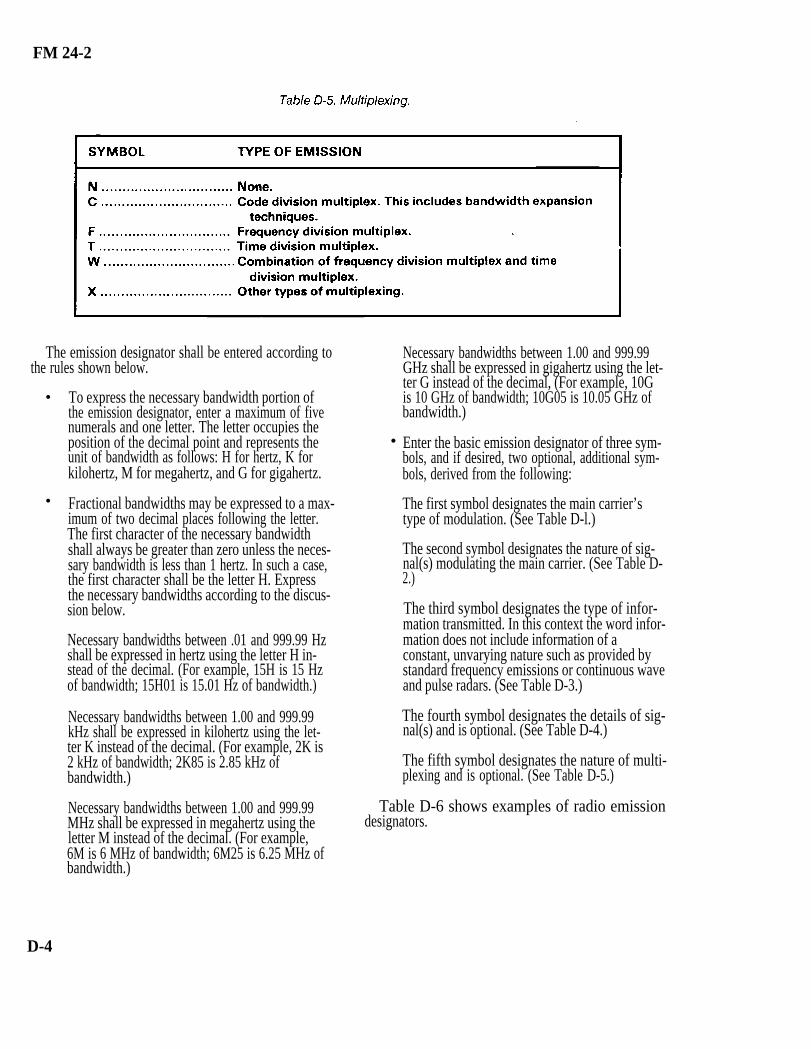
FM 24-2
•
•
The emission designator shall be entered according tothe rules shown below.
To express the necessary bandwidth portion ofthe emission designator, enter a maximum of fivenumerals and one letter. The letter occupies theposition of the decimal point and represents theunit of bandwidth as follows: H for hertz, K forkilohertz, M for megahertz, and G for gigahertz.
Fractional bandwidths may be expressed to a max-imum of two decimal places following the letter.The first character of the necessary bandwidthshall always be greater than zero unless the neces-sary bandwidth is less than 1 hertz. In such a case,the first character shall be the letter H. Expressthe necessary bandwidths according to the discus-sion below.
Necessary bandwidths between .01 and 999.99 Hzshall be expressed in hertz using the letter H in-stead of the decimal. (For example, 15H is 15 Hzof bandwidth; 15H01 is 15.01 Hz of bandwidth.)
Necessary bandwidths between 1.00 and 999.99kHz shall be expressed in kilohertz using the let-ter K instead of the decimal. (For example, 2K is2 kHz of bandwidth; 2K85 is 2.85 kHz ofbandwidth.)
Necessary bandwidths between 1.00 and 999.99MHz shall be expressed in megahertz using theletter M instead of the decimal. (For example,6M is 6 MHz of bandwidth; 6M25 is 6.25 MHz ofbandwidth.)
•
D-4
Necessary bandwidths between 1.00 and 999.99GHz shall be expressed in gigahertz using the let-ter G instead of the decimal, (For example, 10Gis 10 GHz of bandwidth; 10G05 is 10.05 GHz ofbandwidth.)
Enter the basic emission designator of three sym-bols, and if desired, two optional, additional sym-bols, derived from the following:
The first symbol designates the main carrier’stype of modulation. (See Table D-l.)
The second symbol designates the nature of sig-nal(s) modulating the main carrier. (See Table D-2.)
The third symbol designates the type of infor-mation transmitted. In this context the word infor-mation does not include information of aconstant, unvarying nature such as provided bystandard frequency emissions or continuous waveand pulse radars. (See Table D-3.)
The fourth symbol designates the details of sig-nal(s) and is optional. (See Table D-4.)
The fifth symbol designates the nature of multi-plexing and is optional. (See Table D-5.)
Table D-6 shows examples of radio emissiondesignators.

FM 24-2
D-5

FM 24-2
Appendix E
Special-Purpose Frequencies
E-1. Designation 6215.5 kHz Maritime mobile distress (voice)
National and international agreements have designated 8364 kHz Maritime search and rescuespecial-purpose frequencies used for maritime distress,search, and rescue and for aeronautical distress. 40.5 MHz Distress calling
E-2. Frequencies 121.5 MHz Aeronautical distress
Aircraft, ship, and survival craft stations may use the 123.1 MHz On-scene search andfollowing frequencies as long as they follow the ITU RRs. rescue/auxillary
•
•
•
•
•
•
•
•
•
•
—
500 kHz
2182 kHz
3023 kHz
4125 kHz
5680 kHz
aeronautical (voice)
Maritime distress and calling 156.8 MHz Maritime distress and calling
Maritime distress and calling 243 MHz Aeronautical distress
Maritime search and rescue 401.0 to 406.1 MHz Search and rescue satellite
Maritime mobile distress (voice)
Maritime search and rescue
•
•
•
E-1

FM 24-2
Appendix F
Requesting Spectrum Management Assistance
F-1. Electromagnetic Interference Resolution
The multiplying signal systems in government andnongovernment sectors have created substantial spectrumcongestion and have intensified competition forelectromagnetic spectrum space. Electromagneticinterference (EMI) is the major threat to the continued andexpanded use of the electromagnetic spectrum. Within theDOD, several agencies are tasked to assist in EMIresolution. Within the Army, requests are generally sent tothe agencies shown below.
F-2. USAISEC
USAISEC provides consultation and propagationengineering services to requestors in the Army and othergovernment agencies in the following areas:
Electromagnetic system performance analysis.
Electrical design and performance determination
•
•
•
•
•
•
•
•
•
of antennas.
Electromagnetic wave propagation advice.
Propagation forecasts and reliability predictions.
Service requests should include enough details topermit task validation and prioritization. Requests shouldbe addressed as shown below.
MAIL: CommanderUSAISECATTN: ASQB-SET-PFort Huachuca, Arizona 85613-5300
MESSAGE: CDR USAISC FT HUACHUCAAZ//ASQB-SET-P//
TELEPHONE: DSN 879-7685, Area Code(602) 538-7685
F-3. DOD ECAC
DOD ECAC resources are available to research anddevelopment activities and to operational commands.ECAC support areas are as follows:
Spectrum planning.
Emission and susceptibility characteristics evalua-tion.
Deployment and siting analysis.
Consultation services.
Data base listings.
DOD activities are encouraged to make direct contactwith the appropriate deputy director before submittingrequests for ECAC services. Once needs have beendefined, a written request for services should be sent to theaddress shown below.
MAIL: Army Deputy Director (CA)ECAC, North SevernAnnapolis, Maryland 21402
MESSAGE: DIR ECAC ANNAPOLIS MD//CA//
TELEPHONE: DSN 281-2103, Area Code(301) 267-2103
F-1

FM 24-2
Appendix G
Selecting Frequencies for Radio Multichannel Systems
G-1. Frequency Selection/LOS Multichannel
The method of frequency selection depends on theequipment and the configuration of the multichannelcommunications network. Much depends on the radiorelay network. Is it a simple isolated system or a complexsystem? Are there more than two transmitters andreceivers operating at the same location? Does thecomplex system have light and heavy traffic routesinterconnecting and crossing of radio systems? Thesefactors must be considered when selecting a proper,workable frequency assignment plan. Technical manualscovering that equipment describe the method used foreach piece of equipment. This appendix covers the radioset, AN/GRC-103(V) band 1 since it is one of the currentradios used with pulse code modulation (PCM)multiplexing equipment in radio relay systems. Thefrequencies used in this appendix will be those of theAFVGRC-103(V) (band 1220.0 to 404.5 MHz). MSE LOSmultichannel is the newest system fielded. It uses the radioset, AN/GRC-226(V). Frequencies assigned for use areprovided by automated spectrum management by the SCC.
G-2. Interference Between Transmitters andReceivers
The purpose of any frequency plan is to minimize theeffects of mutual interference. With a radio set operatingfull duplex, the transmitting power is usually millions oftimes greater than the power of the receiver’s signal. Thereceiver must be able to reject the transmitter signal andselect the weak signal to which it is tuned.
To reject a transmitted signal, a receiver must beseparated from the transmitter by so many channelsaccording to the radio being used (see proper technicalmanual).
This separation is called a guard band. When using theAN/GRC-103(V), the transmitting frequencies at a stationmust be well separated from the receiver frequencies toguard against transmitter- to-receiver interference. This isdone by setting up a frequency guard band of 16.5 MHz (33channels) between the transmitter and receiver frequency.
The receiving frequencies at a station must be wellseparated from each other to guard againstreceiver-to-receiver interference. This is done by operatingthe receiver so at least three unused frequency channels(1.5 MHz) separate the operating frequency of any tworeceivers.
Two methods that reduce the required frequencyseparation between systems from 16.5 MHz (33 channels)to 5 MHz (10 channels) are cross-polarization andseparate masts.
Sometimes antennas on neighboring masts may becross- polarized to advantage. (loss-polarization is havingone antenna polarized in one plane (horizontal or vertical)and the other antenna polarized in the other plane.Cross-polarization results in a greater isolation betweenantennas on the same mast or neighboring masts. It alsopermits the separation between transmitting and receivingfrequencies on these antennas to be much smaller than withnoncross- polarized antennas (Figure G-l).
In applicable systems, using separate masts fortransmitters and receivers at a station reduces thetransmitter-to-receiver interference at that station. Thisisolation can be further improved by using verticalpolarization for one antenna and horizontal polarizationfor the other.
G-1

FM 24-2
G-3. Two-Block Frequency Assignment Plan
The two-block plan is used for simple isolated systems.An isolated route is one which does not cross or connectwith any other radio-relay routes. For example, a systemmay consist of two terminals and three repeaters (FigureG-2) with the radios operating between 220.0 and 404.5MHz.
To set up a two-block plan, arrange the frequencies innumerical sequence (lowest to highest). Divide theavailable frequencies into two blocks that contain equalnumbers of frequencies. Arrange them so each frequencyin the first block may be paired with a frequency in thesecond block which is separated from the lower frequency(Block I) by at least 16.5 MHz (Figure G-3).
Assign transmitting frequencies beginning at terminal Aby selecting a frequency from Block I and then from BlockII (Figure G-3). Assign all transmitting frequencies in anA to B direction; then assign frequencies in the samemanner from a B to A direction (Figure G-4).
Ensure to maintain the minimum requiredreceiver-to-receiver separations at all sites where two ormore receivers are located. In this case, it would be thethree repeaters that would have to be checked for properreceiver-to-receiver separation. For this reason,frequencies from a specific block may not always beassigned consecutively.
G-2

FM 24-2
The two-block plan can be used for a simple parallelsystem. Tangent systems from any site in the parallel systemto other sites maybe established. This is possible becausefrom any site in a paralleled system all transmitterfrequencies are from one block, and the distant transmitterwould transmit on a frequency from the opposite block.The two-block plan does not provide for alternate routingor operating among three different sites. When systemsbecome too complex, the six-block ABM frequencyassignment plan should be used.
G-4. Six-Block ABM Frequency Assignment Plan
The six-block ABM plan is used for a complex systemwith two or more transmitters and two or more receiversat the same location (Figure G-5). (The letters A, B, andM have no significant meaning.)
The ABM plan divides a broad frequency assignmentlist (all or a large part of a band allocated) into sixfrequency blocks (or lists) of suitable widths. Frequenciesobtained are divided equally among the six blocks. Thebasic planning is then done in terms of these blocks.Advantages of the six-block plan are shown below.
Any station can be connected with almost anyother station with minimum effect on the rest ofthe network.
•
•
•
•
Planning is simplified.
Quick frequency changes can be accomplishedwithout any trouble.
By dividing all frequencies into six blocks all as-signed frequencies are usable.
The necessary guard band between the transmit-ter and receiver frequencies is obtained.
To use the ABM plan, designate each site with the letterA, B, or M. Be sure that sites with the same letter are notinterconnected (Figure G-6). Following this rule, locationA can establish radio links with locations B or M but notwith another A.
Considering all possible radio links, a triangle can bedrawn as shown in Figure G-7A. Radio sets used in multi-channel systems do not require transmitter-to-transmitterseparation; therefore, all transmitter frequencies can betaken from the same block if necessary. Considering trans-mitter frequencies only, six groups or blocks of frequenciesare required for the triangle. These blocks of frequenciesare numbered I through VI. At location A, I and II are thetransmitting frequencies and IV and V are the receivingfrequencies.
•
G-3

FM 24-2
To set up a system between A and M, the transmitterfrequencies at A must be from Block I and the receiverfrequencies at A must be from Block IV. Each system hasa designated block from which the frequencies are taken(Figure G-7B). To set up a system from B to M, find theblock where B transmits and M receives. In this case, it isVI.
Six blocks of frequencies are required when consideringthe six transmitter frequencies from the triangle situation.The required separations between the blocks (thetransmitter separation from receiver frequency by at least16.5 MHz or more) are also considered. From the trianglesituation to a more complex situation such as Figure G-8,it is necessary to determine the number of frequenciesrequired in each block. To do this, the system requirementsmust be analyzed. (We no longer just divide the frequenciesequally into the six blocks.)
From Figure G-8, it can be seen that three transmitterfrequencies are required for the A to M systems. Thus, aminimum of three frequencies are required in Block I forA to M. Continue the system analysis by counting Block IIA to B frequencies, and then count Block III B to Mfrequencies. It is not necessary to determine the number offrequencies in Block IV, V, and VI because countingBlocks I, II, and III gives half the total number offrequencies for the entire system. Referring to Figures G-8and G-9, note that in Block I a minimum of threefrequencies is required in the A-M direction. Sincefrequencies on these systems are assigned in pairs, a totalof at least three frequencies will be required in Block IV.Figure G-9 shows the requirements for the entire system.
G-4

FM 24-2
When spare frequencies are assigned above therequired number for the systems, the spare frequenciesmust be kept in numerical sequence with the other assignedfrequencies and divided equally among the blocks. Forexample, if six spares are assigned, add them to thesequential listing, then add one more frequency to eachblock above the requirement (that is, Block 1, fourfrequencies; Block II, five frequencies). These sparefrequencies may be used for displacement systems oradditional systems above the amount estimated for theoperation.
Frequencies may then be assigned to the system (FigureG-10). The transmitting frequency is always located next tothe terminal or relay symbol. Refer to the analysis of systemrequirements to determine what direction each system isdesignated, such as A-M, A-B, or M-B; frequencies will beassigned in pairs for each system. For example, in Figure
G-8, the first A-M system counted was from the divisionartillery to the division tactical air command (TAC). FromFigure G-9, assign the first frequency in Block I (222.0MHz) to division artillery for their transmit to TAC; at thesame time, assign the first frequency in Block IV (261.0MHz) as the transmit frequency from TAC to divisionartillery. If this procedure is followed exactly for eachsystem, then transmitter- to-receiver separation will not bea problem. However, care must be taken at multichannelrelays and terminals to ensure that receiver-to-receiverseparations (1.5 MHz) are observed. Remember, the 1.5MHz required separation pertains only to theAN/GRC-103 in these examples. For other radio sets,check the proper technical manuals.
The suggested method of assigning frequencies to radiorelay systems is to assign frequencies in the priority usedfor establishing systems (command links, area links, logistic
G-5

FM 24-2
links, and so on). Figure G-10 shows all frequenciesassigned to all systems with the proper guard bands.
G-5. Limitations of Frequency Assignment Plans
The frequency assignment plans that have beendiscussed have limitations. Generally, a two-blockfrequency plan will work for any simple isolated systemregardless of the radio sets used. However, whenfrequencies are needed for complex systems with two ormore transmitters and receivers at the same location, newproblems arc often encountered.
The ABM plan is not the answer to eliminating allmutual interference problems encountered within allcomplex systems. When the frequencies used with someradio sets are broken down into blocks according to theABM plan and other plans and the required frequencyseparations for the particular radio sets are maintained,problems with harmonics (multiple of a base frequency)are sometimes encountered. This problem can becomeeven more complex in sophisticated frequency diversity
G-6
troposcatter systems where the base band signal applies totwo or more transmitters operating on differentfrequencies and receives on two or more receivers.
Each radio set has different sensitivity, selectivity, andother technical characteristics. When two or more systemsuse the same site, frequency separation between thetransmit and receiver antenna on different masts becomesa critical consideration. A receiver acted on by certain baseor harmonic frequencies from a transmitter located at thesame location will encounter mutual interference. Becauseof this, a required frequency separation will have to bemaintained between transmitters and receivers. Properantenna orientation will have to be maintained betweenantennas. The required frequency separation betweentransmitters and receivers is not the same for all radio sets.When the receivers of some radio sets are located back-to-back as relay stations (repeaters), a differentfrequency separation may be required between thereceivers than the frequency separation normally requiredwhen the receivers are located separately at the samelocation.
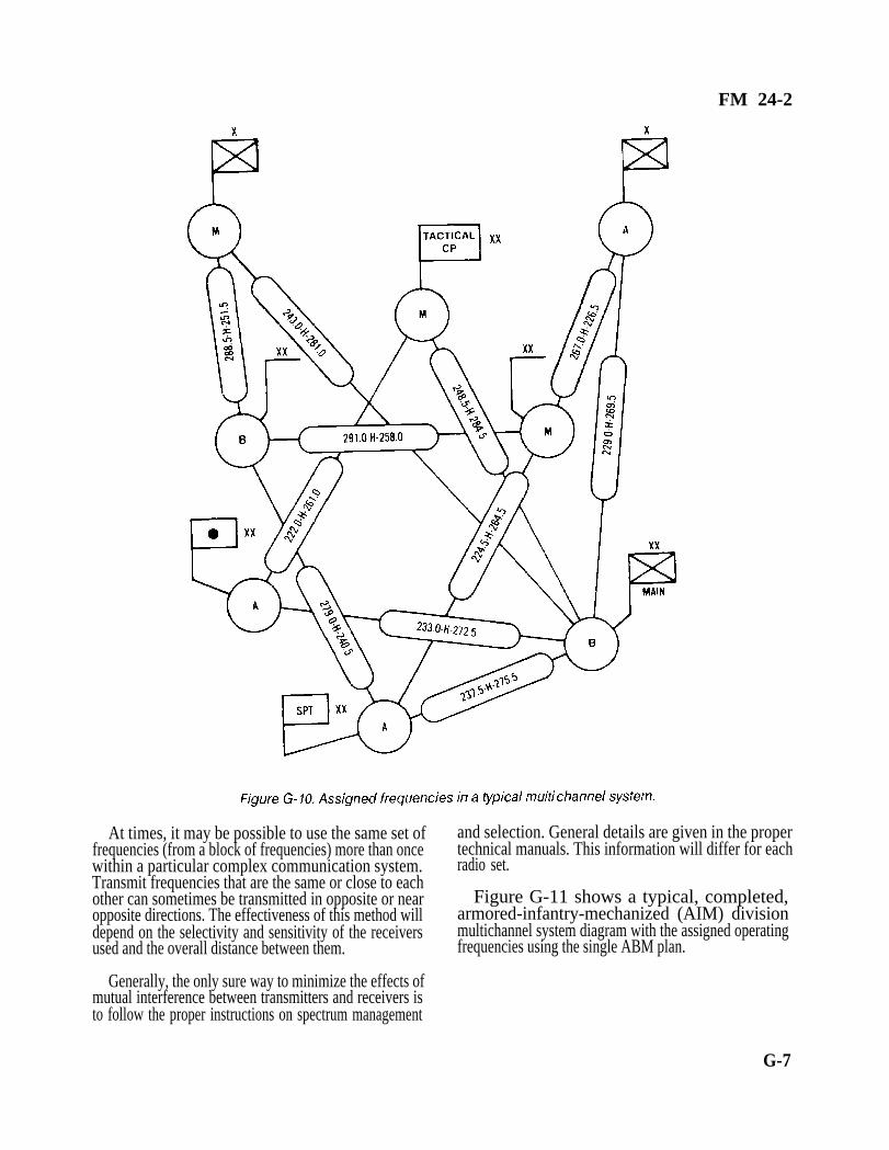
FM 24-2
At times, it may be possible to use the same set of and selection. General details are given in the properfrequencies (from a block of frequencies) more than once technical manuals. This information will differ for eachwithin a particular complex communication system. radio set.Transmit frequencies that are the same or close to eachother can sometimes be transmitted in opposite or near Figure G-11 shows a typical, completed,opposite directions. The effectiveness of this method will armored-infantry-mechanized (AIM) divisiondepend on the selectivity and sensitivity of the receivers multichannel system diagram with the assigned operatingused and the overall distance between them. frequencies using the single ABM plan.
Generally, the only sure way to minimize the effects ofmutual interference between transmitters and receivers isto follow the proper instructions on spectrum management
G-7

FM 24-2
G-8

FM 24-2
Appendix H
Hopset Construction
H-1. Introduction
A hopset is a list of frequencies the spectrum managerauthorizes a particular unit to use. A list of discretefrequencies or ranges and groups of frequencies specify thehopset.
Many frequency hopping (FH) or frequency agileequipment is either fielded or under development. Whilenot all of these are communications equipment, the factorsin constructing hopsets are basically the same.
An FH or agile transmitter changes frequency withina given frequency band in either a random, pseudorandom,or fixed order. Generally, this is done as ECCM, but, insome cases, is done when the equipment sensesinterference on a specific frequency. The number offrequencies used within the given frequency band canrange from a dozen to several thousand. Normally, themore frequencies available in the required frequency bandfor inclusions in the hopset, the more effectively theequipment functions.
H-2. Construction Process
For this discussion, assume a corpswide hopset is beingconstructed for SINCGARS. The corps G6 is thefrequency assignment authority for the band being used.
The entire construction process is actually one ofsubtraction. The frequency resource needed by the FH oragile transmitter is normally shared with other equipment,such as between SINCGARS and MSE, and radio accessunits (RAUs) and mobile subscriber radiotelephoneterminals (MSRTs). The spectrum manager must considerthe impact of the hopper on nonhopping assignments.Possible interference to existing users must be evaluated,and if the interference is determined to be unacceptable,those frequencies must be deleted from the frequencyresource. The spectrum manager must also delete allassignments that have been designated by corps, higherheadquarters, or civil authorities as restricted from thefrequency resource.
To develop a truly corpswide hopset, the spectrummanager must consider all restrictions on frequency useimposed by divisions within their areas of operation. It may
be that all of these frequencies were considered during theprocess discussed above.
Any frequency restrictions that apply to corps boundaryareas must be considered and coordinated with theadjacent corps. Frequencies restricted in the boundaryareas may be deleted from the frequency resource.
Using FH or agile transmitter in an aircraft can imposeadditional restrictions. Not only does the process discussedabove apply, but also due to the increase in the radiohorizon, additional consideration with adjacent corps willhave to be made. This could lead to more frequencies beingdeleted from the frequency resource. This results in a muchsmaller hopset.
The spectrum manager starts the planning process bycompiling all the frequency requirements from thesubordinate units. He combines the subordinate unitrequirements with those of his echelon.
The spectrum manager assigns frequencies based on thefollowing criteria:
Network priority.
Equipment in use.
Equipment separation.
Retransmission requirements.
Frequency use restrictions.
The spectrum manager assigns the maximum number offrequencies available in the area of operation and spreadsthe frequencies in the hopsets across the widest possibleband to optimize ECCM capabilities. Spreading thefrequencies across the frequency band is more importantthan increasing the total number of frequencies available.Fifty frequencies spread from 30 to 88 MHz are moreeffective than 100 frequencies from 35 to 40 MHz. Chancesare very slight that an enemy jammer can cover the entire58 MHz range or even a small portion of it with enoughpower to disrupt communications; however, a jammercould barrage jam the entire 5 MHz range.
•
•
•
•
•
H-1

FM 24-2
The spectrum manager, with the signal planningelement, uses the BECs computer to assign frequencies tohopsets. The computer mathematically manipulates thefrequencies based on the restrictions the spectrummanager enters into the data base. The computer developshopsets by correlating the restrictions with availableresources.
Hopsets should maximize use of frequencies separatefrom any collocated networks. This requires knowledge ofnetwork structures and which nets are collocated. Thespectrum manager must work closely with G3/S3 tominimize the effects on collocated networks.
To minimize possible interference betweenSINCGARS and MSRTs/RAUs, SINCGARS can beprogrammed to lock out certain frequencies from thehopset. Neither BECS nor the MSE SCC can engineerfrequency use for both systems at the same time. Thespectrum manager must plan the MSRT/RAU frequencies(up to 96 pairs) with the SCC (assigns MSRT/RAUfrequencies) and enter them into the BECS computer aslockout sets. Frequency interference between the radiosystems is minimized, particularly the cosite systems.
H-3. Considerations
Corps and division level communications are currentlyupgrading to MSE and fielding SINCGARS as a combatnet radio. Both systems use the same frequency band andmutual interference has been noted.
Covehicular interference is the worst. Currently, thereis no technical solution and no planned fix until MSE andSINCGARS are totally fielded. The area most affected by
•
•
•
•
•
•
H-2
this interference is the brigade area. Users in this area needto be aware of the potential problem and given theoperational work-arounds to overcome the interference.
There are three methods/work-arounds that helpovercome the interference problem. No one methodeliminates all interference. The three methods are--
Time-sharing. The best answer to the vehicleproblem is prioritize the device needed by themission, situation, and echelon.
Spectrum-sharing. Lock out MSRT/RAU fre-quencies on SINCGARS in the FH mode ordelete from frequency resource for SINCGARSin the SINGLE-CHANNEL mode.
Antenna separation. The best alternative avail-able for the fried locations but is not possible formobile users.
Common sense remains the best defense to resolve thisinterference. Standard communications principles andsignal doctrine should be followed.
Use lowest power possible to maintain combatnet radio nets.
Keep transmissions short for combat net radioand MSRT calls.
Keep vehicles using communications systemsseparated during convoy and during halts.
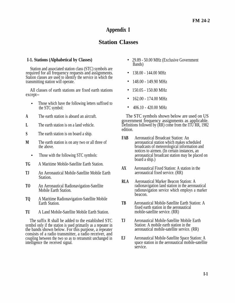
FM 24-2
Appendix I
Station Classes
I-1. Stations (Alphabetical by Classes)
Station and associated station class (STC) symbols arerequired for all frequency requests and assignments.Station classes are used to identify the service in which thetransmitting station will operate.
All classes of earth stations are fixed earth stationsexcept--
•
•
•
•
•
•
A
L
S
M
TG
TJ
TO
TQ
TU
•
•
Those which have the following letters suffixed tothe STC symbol:
The earth station is aboard an aircraft.
The earth station is on a land vehicle.
The earth station is on board a ship.
The earth station is on any two or all three ofthe above.
Those with the following STC symbols:
A Maritime Mobile-Satellite Earth Station.
An Aeronautical Mobile-Satellite Mobile EarthStation.
An Aeronautical Radionavigation-SatelliteMobile Earth Station.
A Maritime Radionavigation-Satellite MobileEarth Station.
A Land Mobile-Satellite Mobile Earth Station.
The suffix R shall be added to the established STCsymbol only if the station is used primarily as a repeater inthe bands shown below. For this purpose, a repeaterconsists of a radio transmitter, a radio receiver, andcoupling between the two so as to retransmit unchanged inintelligence the received signal.
29.89 - 50.00 MHz (Exclusive GovernmentBands)
138.00 - 144.00 MHz
148.00 - 149.90 MHz
150.05 - 150.80 MHz
162.00 - 174.00 MHz
406.10 - 420.00 MHz
The STC symbols shown below are used on USgovernment frequency assignments as applicable.Definitions followed by (RR) come from the ITU RR, 1982edition.
FAB
AX
RLA
TB
TJ
EJ
Aeronautical Broadcast Station: Anaeronautical station which makes scheduledbroadcasts of meteorological information andnotices to airmen. (In certain instances, anaeronautical broadcast station may be placed onboard a ship.)
Aeronautical Fixed Station: A station in theaeronautical fixed service. (RR)
Aeronautical Marker Beacon Station: Aradionavigation land station in the aeronauticalradionavigation service which employs a markerbeacon.
Aeronautical Mobile-Satellite Earth Station: Afixed earth station in the aeronauticalmobile-satellite service. (RR)
Aeronautical Mobile-Satellite Mobile EarthStation: A mobile earth station in theaeronautical mobile-satellite service. (RR)
Aeronautical Mobile-Satellite Space Station: Aspace station in the aeronautical mobile-satelliteservice.
I-1

FM 24-2
RLB
TZ
TO
EO
FA
FLEA
MOEA
FLU
Aeronautical Radiobeacon Station: Aradiobeacon station in the aeronauticalradionavigation service intended for the benefitof aircraft.
Aeronautical Radionavigation-Satellite EarthStation: A fixed earth station in the aeronauticalradionavigation-satellite service.
Aeronautical Radionavigation-Satellite MobileEarth Station: A mobile earth station in theaeronautical radionavigation-satellite service.(RR)
Aeronautical Radionavigation-Satellite SpaceStation: A space station in the aeronauticalradionavigation-satellite service. (RR)
Aeronautical Station: A land station in theaeronautical mobile service. In certaininstances, an aeronautical station may belocated, for example, on board ship or on aplatform at sea. (RR)
Aeronautical Telemetering Land Station: Atelemetering land station used in the flighttesting of manned or unmanned aircraft,missiles, or major components thereof.
Aeronautical Telemetering Mobile Station: Atelemetering mobile station used in testing ofmanned or unmanned aircraft, missiles, ormajor components thereof.
Aeronautical Utility Land Station: A land station
TW
located at airdome control towers and used forcontrol of ground vehicles and aircraft on theground at airdromes.
MOU Aeronautical Utility Mobile Station: A mobilestation used for communication at airdromeswith the aeronautical utility land station, theairdrome control station, the Federal AviationAdministration flight service station, groundvehicles, and aircraft on the ground. (Alltransmissions shall be subject to the control ofthe airdrome control station and shall bediscontinued immediately when so requested bythe airdrome control operators.)
MA Aircraft Station: A mobile station in theaeronautical mobile service, other than a
I-2
FAC
ROA
FB
EB
EV
BC
BT
FC
EW
TP
TE
XM
survival craft station, located on board anaircraft. (RR)
Airdrome Control Station: An aeronauticalstation providing communication between anairdrome control tower and aircraft.
Altimeter Station: A radionavigation mobilestation in the aeronautical radionavigationservice which employs a radio altimeter.
Base Station: A land station in the land mobileservice. (RR)
Broadcasting-Satellite Space Station (soundbroadcasting): A space station (soundbroadcasting) in the broadcasting-satelliteservice. (RR)
Broadcasting-Satellite Space Station(television): A space station (television) in thebroadcasting-satellite service. (RR)
Broadcasting Station (sound): A station (sound)in the broadcasting service. (RR)
Broadcasting Station (television): A station(television) in the broadcasting service. (RR)
Coast Station: A land station in the maritimemobile service. (RR)
Earth Exploration-Satellite Earth Station: Anearth station in the earth exploration-satelliteservice. (RR)
Earth Exploration-Satellite Space Station: Aspace station in the earth exploration-satelliteservice. (RR)
Earth Station (receiving): An earth station usedfor receiving. (RR) (TP is not used onapplications.)
Earth Station (transmitting): An earth stationused for transmitting. (RR) (TE is not used onapplications.)
Experimental Composite Station: Anexperimental station used in experimentaloperations of a complex nature not readilyspecified or used in operation which is a

FM 24-2
XC
XD
XE
XR
EX
XT
TC
EC
FX
FLEB
composite of two or more of the establishedexperimental categories.
Experimental Contract Developmental Station:An experimental station used for the evaluationor testing under government contract ofelectronics equipment or systems in a design ordevelopment stage.
Experimental Developmental Station: Anexperimental station used for evaluation ortesting of electronics equipment or systems in adesign or development stage.
Experimental Export Station: An experimentalstation intended for export and used for theevaluation or testing of electronics equipmentor systems in the design or development stage.
Experimental Research Station: Anexperimental station used in basic studiesconcerning scientific investigations lookingtoward the improvement of the art ofradiocommunications.
Experimental Station: A station utilizing radiowaves in experiments with a view to thedevelopment of science or technique. Thisdefinition does not include amateur stations.(RR) (EX is not used on applications.)
Experimental Testing Station: An experimentalstation used for the evaluation or testing ofelectronics equipment or systems, including siteselection and transmission path surveys, whichhave been developed for operational use.
Fixed-Satellite Earth Station: An earth station inthe fixed-satellite service. (RR)
Fixed-Satellite Space Station: A space station inthe fixed-satellite service. (RR)
Fixed Station: A station in the fixed service.(RR)
Flight Telemetering Land Station: Atelemetering land station the emissions of whichare used for telemetering to a balloon; to abooster or rocket, excluding a booster or rocketin orbit about the earth or in deep space; or to
an aircraft, excluding a station used in the flighttesting of an aircraft.
MOEB Flight Telemetering Mobile Station: A
FAT
RLG
FXH
FLH
MOH
ES
TY
TU
EU
ML
telemetering mobile station the emissions ifwhich are used for telemetering from a balloon;from a booster or rocket, excluding a booster orrocket in orbit about the earth or in deep space;or from an aircraft, excluding a station used inthe flight testing of an aircraft.
Flight Test Station: An aeronautical station usedfor the transmission of essentialcommunications in connection with the testingof aircraft or major components of aircraft.
Glide Path (Slope) Station: A radionavigationland station in the aeronautical radionavigationservice which employs the Instrument LandingSystem Glide Path.
Hydrologic and Meteorological Fixed Station: Afixed station the emissions of which are used forthe automatic transmission of either hydrologicor meteorological data, or both.
Hydrologic and Meteorological Land Station: Aland station the emissions of which are used forthe automatic transmission of either hydrologicor meteorological data, or both.
Hydrologic and Meteorological Mobile Station:A mobile station the emissions of which areused for the automatic transmission of eitherhydrologic or meteorological data, or both.
Intersatellite Space Station: A space station inthe intersatellite service. (RR)
Land Mobile-Satellite Earth Station: A fixedearth station in the land mobile-satellite service.(RR)
Land Mobile-Satellite Mobile Earth Station: Amobile earth station in the land mobile-satelliteservice. (RR)
Land Mobile-Satellite Space Station: A spacestation in the land mobile-satellite service. (RR)
Land Mobile Station: A mobile station in theland mobile service capable of surface
I-3

FM 24-2
FL
RLL
RLN
FCB
RLM
TI
TG
EG
TX
TQ
EQ
WXD
I-4
movement within the geographical limits of acountry or continent. (RR)
Land Station: A station in the mobile servicenot intended to be used while in motion. (RR)
Localizer Station: A radionavigation landstation in the aeronautical radionavigationservice which employs an Instrument LandingSystem Localizer.
Loran Station: A long distance radionavigationland station transmitting synchronized pulses.Hyperbolic lines of position are determined bythe measurement of the difference in the time ofarrival of these pulses.
Marine Broadcast Station: A coast stationwhich scheduled broadcasts of time,meteorological, and hydrographic information.
Maritime Radiobeacon Station: A radiobeaconstation in the maritime radionavigation serviceintended for the benefit of ships.
Maritime Mobile-Satellite Earth Station: Anearth station in the maritime mobile-satelliteservice at a specified fried point. (RR)
Maritime Mobile-Satellite Mobile Earth Station:A mobile earth station in the maritimemobile-satellite service. (RR)
Maritime Mobile-Satellite Space Station: Aspace station in the maritime mobile-satelliteservice. (RR)
Maritime Radionavigation-Satellite EarthStation: A fixed earth station in the maritimeradionavigation-satellite service. (RR)
Maritime Radionavigation-Satellite MobileEarth Station: A mobile earth station in themaritime radionavigation-satellite service. (RR)
Maritime Radionavigation-Satellite SpaceStation: A space station in the maritimeradionavigation-satellite service. (RR)
Meteorological Radar Station: A station in themeteorological aids service employing radar.
TM
EM
MO
OE
OD
RLO
MAP
MLP
MOP
MRP
MSP
RLC
WXB
Meteorological-Satellite Earth Station: Anearth station in the meteorological-satelliteservice. (RR)
Meteorological-Satellite Space Station: A spacestation in the meteorological-satellite service.(RR)
Mobile Station: A station in the mobile serviceintended to be used while in motion or duringhalts at unspecified points. (RR)
Oceanographic Data Interrogating Station: Astation in the maritime mobile service theemissions of which are used to initiate, modify,or terminate functions of equipment directlyassociated with an oceanographic data station,including the station itself. (RR)
Oceanographic Data Station: A station in themaritime mobile service located on a ship, buoy,or other sensor platform the emissions of whichare used for transmission of oceanographicdata. (RR)
Omnidirectional Range Station: Aradionavigation land station in the aeronauticalradionavigation service providing directindication of the bearing (omnibearing) of thatstation from an aircraft.
Portable Aircraft Station: A portable stationoperating in the aeronautical mobile service.
Portable Land Mobile Station: A portablestation operating in the land mobile service.
Portable Mobile Station: A portable stationoperating in the mobile service.
Portable Radiolocation Station: A portablestation operating in the radiolocation service.
Portable Ship Station: A portable stationoperating in the maritime mobile service.
Radar Beacon (racon) Station: A station whichemploys a radar beacon (racon).
Radar Beacon Precipitation Gage Station: Atransponder station in the meteorological aids

FM 24-2
RA
MOB
TF
TL
EF
RG
LR
MR
RL
service, the emissions of which are used fortelemetering.
Radio Astronomy Station: A station in the radioastronomy service. (RR) (This is always areceiving station.)
Radio Beacon Mobile Station: A mobile stationthe emissions of which are used to determine itslocation.
Radiodetermination-Satellite Earth Station: Afixed earth station in theradiodetermination-service. (RR)
Radiodetermination-Satellite Mobile EarthStation: A mobile earth station in theradiodetermination-satellite service. (RR)
Radiodetermination-Satellite Space Station: Aspace station in the radiodetermination-satelliteservice. (RR)
Radio Direction-Finding Station: Aradiodetermination station using radiodirection-finding. (RR)
Radiolocation Land Station: A station in theradiolocation service not intended to be usedwhile in motion. (RR)
Radiolocation Mobile Station: A station in theradiolocation service intended to be used whilein motion or during halts at unspecified points.(RR)
Radionavigation Land Station: A station in theradionavigation service not intended to be usedwhile in motion. (RR)
RLTM Radionavigation Land Test Station(Maintenance Test Facility): A radionavigationland station in the aeronautical radionavigationservice which is used as a radionavigationcalibration station for the transmission ofessential information in connection with thetesting and calibration of aircraft navigationalaids, receiving equipment, and interrogators atpredetermined surface locations. The primarypurpose of this facility is to permit maintenancetesting by aircraft radio service personnel.
RLTO
RO
TN
EN
RLR
WXR
Radionavigation Land Test Station (operationalTest Facility): A radionavigation land station inthe aeronautical radionavigation service whichis used as a radionavigation calibration stationfor the transmission of essential information inconnection with the testing and calibration ofaircraft navigational aids, receiving equipment,and interrogators at predetermined surfacelocations. The primary purpose of this facility isto permit the pilot to check a radionavigationsystem aboard the aircraft prior to takeoff.
Radionavigation Mobile Station: A station inthe radionavigation service intended to be usedwhile in motion or during halts at unspecifiedpoints. (RR)
Radionavigation-Satellite Earth Station: Anearth station in the radionavigation-satelliteservice. (RR)
Radionavigation-Satellite Space Station: Aspace station in the radionavigation-satelliteservice. (RR)
Radio Range Station: A radionavigation landstation in the aeronautical radionavigationservice providing radial equisignal zones. (Incertain instances a radio range station may beplaced on board a ship.)
Radiosonde Station: A station in themeteorological aids service employing aradiosonde.
WXRG Radiosonde Ground Station: A station in themeteorological aids service employing a groundstation associated with a radiosonde.
MS Ship Station: A mobile station in the maritimemobile service located on board a vessel whichis not permanently moored, other than asurvival craft station. (RR)
SN Sounder Network Station: A station equippedwith an ionosphere sounder used for thereal-time selection of frequencies foroperational communication circuits.
SP Sounder Prediction Station: A station equippedwith an ionosphere sounder for real-timemonitoring of upper atmosphere phenomena or
I-5

FM 24-2
TT
ET
TH
EH
ME
TD
ED
TETD
TETR
TR
ER
TK
to obtain data for the prediction of propagationconditions.
Space Operation Earth Station: An earth stationin the space operation service. (RR)
Space Operation Space Station: A space stationin the space operation service.
Space Research Earth Station: An earth stationin the space research service. (RR)
Space Research Space Station: A space stationin the space research service. (RR)
Space Station: A station located on an objectwhich is beyond, is intended to go beyond, orhas been beyond, the major portion of theearth’s atmosphere. (RR) (ME is not used onapplications.)
Space Telecommand Earth Station: An earthstation the emissions of which are used forspace telecommand. (RR)
Space Telecommand Space Station: A spacestation which receives emissions used for spacetelecommand. (RR)
Space Telecommand Transmitting EarthStation: For an emergency position - indicatingradiobeacon (EPIRB) in a mobile-satelliteservice.
Space Telemetering Transmitting Earth Station:For an emergency position - indicatingradiobeacon (EPIRB) in a mobile-satelliteservice.
Space Telemetering Earth Station: An earthstation which receives emissions used for spacetelemetering. (RR)
Space Telemetering Space Station: A spacestation the emissions of which are used forspace telemetering. (RR)
Space Tracking Earth Station: An earth stationwhich transmits or receives emissions used forspace tracking. (RR)
EK
TETK
SS
EE
FLEC
MOEC
RLS
FAD
MAD
FBD
FCD
Space Tracking Space Station: A space stationwhich transmits or receives and retransmitsemissions used for space tracking. (RR)
Space Tracking Transmitting Earth Station: Foran emergency position - indicating radiobeacon(EPIRB) in a mobile-satellite service.
Standard Frequency and Time Signal Station: Astation in the standard frequency and timesignal service. (RR)
Standard Frequency and Time Signal-SatelliteSpace Station: A space station in the standardfrequency and time signal-satellite service. (RR)
Surface Telemetering Land Station: Atelemetering land station the emissions of whichare intended to be received on the surface of theearth.
Surface Telemetering Mobile Station: Atelemetering mobile station located on thesurface of the earth and the emissions of whichare intended to be received in the surface of theearth.
Surveillance Radar Station: A radionavigationland station in the aeronautical radionavigationservice employing radar to display the presenceof aircraft within its range. (In certain instances,a surveillance radar station may be placed onboard a ship.)
Telecommand Aeronautical Station: A landstation in the aeronautical mobile service theemissions of which are used for terrestrialtelecommand.
Telecommand Aircraft Station: A mobile stationin the aeronautical mobile service the emissionsof which are used for terrestrial telecommand.
Telecommand Base Station: A land station inthe land mobile service the emissions of whichare used for terrestrial telecommand.
Telecommand Coast Station: A land station inthe maritime mobile service the emissions ofwhich are used for terrestrial telecommand.
I-6

FM 24-2
FXD
FLD
MLD
MOD
MSD
FXE
FLE
MOE
Telecommand Fixed Station: A fixed station theemissions of which are used for terrestrialtelecommand.
Telecommand Land Station: A land station theemissions of which are used for terrestrialtelecommand.
Telecommand Land Mobile Station: A mobilestation in the land mobile service the emissionsof which are used for terrestrial telecommand.
Telecommand Mobile Station: A mobile stationthe emissions of which are used for terrestrialtelecommand.
Telecommand Ship Station: A mobile station inthe maritime mobile service the emissions ofwhich are used for terrestrial telecommand.
Telemetering Fixed Station: A fixed station theemissions of which are used for telemetering.
Telemetering Land Station: A land station theemissions of which are used for telemetering.
Telemetering Mobile Station: A mobile stationthe emissions of which are used for telemetering,
1-2. Stations (Alphabetical Symbols)
STC symbols shown below are used on US governmentfrequency assignments as applicable.
AX
BC
BT
EB
EC
ECED
ECEK
Aeronautical Fixed Station.
Broadcasting Station (sound).
Broadcasting Station (television).
Broadcasting-Satellite Space Station (soundbroadcasting).
Fixed-Satellite Space Station.
Space Telecommand Space Station in thefixed-satellite service.
Space Tracking Space Station in thefixed-satellite service.
ECER
ED
EE
EF
EFED
EFEK
EFER
EG
EGED
EGEK
EGER
EH
EHED
EHEK
EHER
EJ
EJED
EJEK
EJER
Space Telemetering Space Station in thefixed-satellite service.
Space Telecommand Space Station.
Standard Frequency and Time Signal-SatelliteSpace Station.
Radiodetermination-Satellite Space Station.
Space Telecommand Space Station in theradiodetermination-satellite service.
Space Tracking Space Station in theradiodetermination-satellite service.
Space Telemetering Space Station in theradiodetermination-satellite service.
Maritime Mobile-Satellite Space Station.
Space Telecommand Space Station in themaritime mobile- satellite service.
Space Tracking Space Station in the maritimemobile-satellite service.
Space Telemetering Space Station in themaritime mobile-satellite service.
Space Research Space Station.
Space Telecommand Space Station in the spaceresearch service.
Space Tracking Space Station in the spaceresearch service.
Space Telemetering Space Station in the spaceresearch service.
Aeronautical Mobile-Satellite Space Station.
Space Telecommand Space Station in theaeronautical mobile-satellite service.
Space Tracking Space Station in theaeronautical mobile-satellite service.
Space Telemetering Space Station in theaeronautical mobile-satellite service.
I-7

FM 24-2
EK Space Tracking Space Station.
EM Meteorological-Satellite Space Station.
EMED Space Telecommand Space Station in themeteorological-satellite service.
EMEK Space Tracking Space Station in themeteorological-satellite service.
EMER Space Telemetering Space Station in themeteorological-satellite service.
EN Radionavigation-Satellite Space Station.
ENED Space Telecommand Space Station in theradionavigation-satellite service.
ENEK Space Tracking Space Station in theradionavigation-satellite service.
ENER Space Telemetering Space Station in theradionavigation-satellite service.
EO Aeronautical Radionavigation-Satellite SpaceStation.
EOED Space Telecommand Space Station in theaeronautical radionavigation-satellite service.
EOEK Space Tracking Space Station in the aeronauticalradionavigation-satellite service.
EOER Space Telemetering Space Station in theaeronautical radionavigation-satellite service.
EQ Maritime Radionavigation-Satellite SpaceStation.
EQED Space Telecommand Space Station in themaritime radionavigation-satellite service.
EQEK Space Tracking Space Station in the maritimeradionavigation-satellite service.
EQER Space Telemetering Space Station in themaritime radionavigation-satellite service.
ER Space Telemetering Space Station.
ES Intersatellite Space Station.
ESED
ESEK
ESER
ET
ETED
ETEK
ETER
EU
EUED
EUEK
EUER
EV
EW
EWED
EWEK
EWER
EX
Space Telecommand Space Station in theintersatellite service.
Space Tracking Space Station in the intersatelliteservice.
Space Telemetering Space Station in theintersatellite service.
Space Operation Space Station.
Space Telecommand Space Station in the spaceoperation service.
Space Tracking Space Station in the spaceoperation service.
Space Telemetering Space Station in the spaceoperation service.
Land Mobile-Satellite Space Station.
Space Telecommand Space Station in the landmobile-satellite service.
Space Tracking Space Station in the landmobile-satellite service.
Space Telemetering Space Station in the landmobile-satellite service.
Broadcasting-Satellite Space Station (television).
Earth Exploration-Satellite Space Station.
Space Telecommand Space Station in the earthexploration-satellite service.
Space Tracking Space Station in the earthexploration-satellite service.
Space Telemetering Space Station in the earthexploration-satellite service.
Experimental Station.
FA Aeronautical Station.
FAB Aeronautical Broadcast Station.
FAC Airdome Control Station.
I-8

FM 24-2
FAD
FAT
FB
FC
FCB
FL
FLD
FLE
FLEA
FLEB
FLEC
FLH
FLU
FX
FXD
FXE
FXH
LR
MA
MAD
MAP
ME
ML
MLP
MO
MOB
Telecommand Aeronautical Station.
Flight Test Station.
Base Station.
Coast Station.
Marine Broadcast Station.
Land Station.
Telecommand Land Station.
Telemetering Land Station.
Aeronautical Telemetering Land Station.
Flight Telemetering Land Station.
Surface Telemetering Land Station.
Hydrologic and Meteorological Land Station.
AeronauticaI Utility Land Station.
Fixed Station.
Telecommand Fixed Station.
Telemetering Fixed Station.
Hydrologic and Meteorological Fixed Station.
Radiolocation Land Station.
Aircraft Station.
Telecommand Aircraft Station
Portable Aircraft Station.
Space Station.
Land Mobile Station.
Portable Land Mobile Station.
Mobile Station.
Radiobeacon Mobile Station.
MOD Telecommand Mobile Station.
MOE Telemetering Mobile Station.
MOEA Aeronautical Telemetering Mobile Station.
MOEB Flight Telemetering Mobile Station.
MOEC Surface Telemetering Mobile Station.
MOH
MOP
MOU
MR
MRP
MS
MSD
MSP
OD
OE
RA
RG
RL
RLA
RLB
RLC
RLG
RLL
RLM
RLN
RLO
Hydrologic and Meteorological Mobile Station.
Portable Mobile Station.
Aeronautical Utility Mobile Station.
Radiolocation Mobile Station.
Portable Radiolocation Station.
Ship Station.
Telecommand Ship Station.
Portable Ship Station.
Oceanographic Data Station.
Oceanographic Data Interrogating Station.
Radio Astronomy Station.
Radio Direction-Finding Station.
Radionavigation Land Station.
Aeronautical Marker Beacon Station.
Aeronautical Radiobeacon Station.
Radar Beacon (racon) Station.
Glide Path (Slope) Station.
Localizer Station.
Marine Radiobeacon Station.
Loran Station.
Omnidirectional Range Station.
I-9
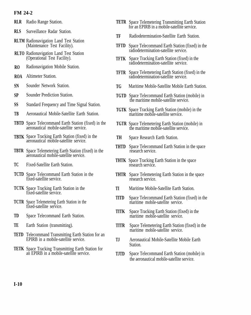
FM 24-2
RLR
RLS
RLTM
RLTO
RO
ROA
SN
SP
SS
TB
TBTD
TBTK
TBTR
TC
TCTD
TCTK
TCTR
TD
TE
TETD
TETK
I-10
Radio Range Station.
Surveillance Radar Station.
Radionavigation Land Test Station(Maintenance Test Facility).
Radionavigation Land Test Station(Operational Test Facility).
Radionavigation Mobile Station.
Altimeter Station.
Sounder Network Station.
Sounder Prediction Station.
Standard Frequency and Time Signal Station.
Aeronautical Mobile-Satellite Earth Station.
Space Telecommand Earth Station (fixed) in theaeronautical mobile-satellite service.
Space Tracking Earth Station (fixed) in theaeronautical mobile-satellite service.
Space Telemetering Earth Station (fixed) in theaeronautical mobile-satellite service.
Fixed-Satellite Earth Station.
Space Telecommand Earth Station in thefixed-satellite service.
Space Tracking Earth Station in thefixed-satellite service.
Space Telemetering Earth Station in thefixed-satellite service.
Space Telecommand Earth Station.
Earth Station (transmitting).
Telecommand Transmitting Earth Station for anEPIRB in a mobile-satellite service.
Space Tracking Transmitting Earth Station foran EPIRB in a mobile-satellite service.
TETR
TF
TFTD
TFTK
TFTR
TG
TGTD
TGTK
TGTR
TH
THTD
THTK
THTR
TI
TITD
TITK
TITR
TJ
TJTD
Space Telemetering Transmitting Earth Stationfor an EPIRB in a mobile-satellite service.
Radiodetermination-Satellite Earth Station.
Space Telecommand Earth Station (fixed) in theradiodetermination-satellite service.
Space Tracking Earth Station (fixed) in theradiodetermination-satellite service.
Space Telemetering Earth Station (fixed) in theradiodetermination-satellite service.
Maritime Mobile-Satellite Mobile Earth Station.
Space Telecommand Earth Station (mobile) inthe maritime mobile-satellite service.
Space Tracking Earth Station (mobile) in themaritime mobile-satellite service.
Space Telemetering Earth Station (mobile) inthe maritime mobile-satellite service.
Space Research Earth Station.
Space Telecommand Earth Station in the spaceresearch service.
Space Tracking Earth Station in the spaceresearch service.
Space Telemetering Earth Station in the spaceresearch service.
Maritime Mobile-Satellite Earth Station.
Space Telecommand Earth Station (fixed) in themaritime mobile-satellite service.
Space Tracking Earth Station (fixed) in themaritime mobile-satellite service.
Space Telemetering Earth Station (fixed) in themaritime mobile-satellite service.
Aeronautical Mobile-Satellite Mobile EarthStation.
Space Telecommand Earth Station (mobile) inthe aeronautical mobile-satellite service.

FM 24-2
TJTK
TJTR
TK
TL
TLTD
TLTK
TLTR
TM
TMTD
TMTK
TMTR
TN
TNTD
TNTK
TNTR
TO
TOTD
TOTK
Space Tracking Earth Station (mobile) in theaeronautical mobile-satellite service.
Space Telemetering Earth Station (mobile) inthe aeronautical obile-satellite service.
Space Tracking Earth Station.
Radiodetermination-Satellite Mobile EarthStation.
Space Telecommand Earth Station (mobile) inthe radiodetermination-satellite service.
Space Tracking Earth Station (mobile) in theradiodetermination-satellite service.
Space Telemetering Earth Station (mobile) inthe radiodetermination-satellite service.
Meteorological-Satellite Earth Station.
Space Telecommand Earth Station in themeteorological-satellite service.
Space Tracking Earth Station in themeteorological-satellite service.
Space Telemetering Earth Station in themeteorological-satellite service.
Radionavigation-Satellite Earth Station.
Space Telccommand Earth Station in theradionavigation-satellite service.
Space Tracking Earth Station in theradionavigation-satellite service.
Space Telemetering Earth Station in theradionavigation-satellite service.
Aeronautical Radionavigation-Satellite MobileEarth Station.
Space Telecommand Earth Station (mobile) inthe aeronautical radionavigation-satelliteservice.
Space Tracking Earth Station (mobile) in theaeronautical radionavigation-satellite service.
TOTR Space Telemetering Earth Station (mobile) inthe aeronautical radionavigation-satelliteservice.
TP Earth Station (receiving).
TQ Maritime Radionavigation-Satellite MobileEarth Station.
TQTD Space Telecommand Earth Station (mobile) inthe maritime radionavigation-satellite service.
TQTK Space Tracking Earth Station (mobile) in themaritime radionavigation-satellite service.
TQTR Space Telemetering Earth Station (mobile) inthe maritime radionavigation-satellite service.
TR Space Telemetering Earth Station.
TT Space Operation Earth Station.
TTTD Space Telecommand Earth Station in the spaceoperation service.
TITK Space Tracking Earth Station in the spaceoperation service.
TTTR Space Telemetering Earth Station in the spaceoperation service.
TU Land Mobile-Satellite Mobile Earth Station.
TUTD Space Telecommand Earth Station (mobile) inthe land mobile-satellite service.
TUTK Space Tracking Earth Station (mobile) in theland mobile-satellite service.
TUTR Space Telemetering Earth Station (mobile) inthe land mobile-satellite service.
Earth Exploration-Satellite Earth Station.
TWTD Space Telecommand Earth Station in the earthexploration-satellite service.
TWTK Space Tracking Earth Station in the earthexploration-satellite service.
TWTR Space Telemetering Earth Station in the earthexploration-satellite service.
TW
I-11

FM 24-2
TX
TXTD
TXTK
TXTR
TY
TYTD
TYTK
TYTR
TZ
TZTD
TZTK
Maritime Radionavigation-Satellite EarthStation
Space Telecommand Earth Station (fixed) in themaritime radionavigation-satellite service.
Space Tracking Earth Station (fixed) in themaritime radionavigation-satellite service.
Space Telemetering Earth Station (fixed) in themaritime radionavigation-satellite service.
Land Mobile-Satellite Earth Station.
Space Telecommand Earth Station (fixed) in theland mobile-satellite service.
Space Tracking Earth Station (fixed) in the landmobile-satellite service.
Space Telemetering Earth Station (fixed) in theland mobile-satellite service.
Aeronautical Radionavigalion-Satellite EarthStation.
Space Telecommand Earth Station (fixed) in theaeronautical radionavigalion-satellite service.
Space Tracking Earth Station (fixed) in theaeronautical radionavigation-satellite service.
TZTR
WXB
WXD
WXR
XC
XD
XE
XM
XR
XT
Space Telemetering Earth Station (fixed) in theaeronautical radionavigation-satellite service.
Radar Beacon Precipitation Gage Station.
Meteorological Radar Station.
Radiosonde Station.
Experimental Contract Developmental Station.
Experimental Developmental Station.
Experimental Export Station.
Experimental Composite Station.
Experimental Research Station.
Experimental Testing Station.
I-3. Services, Station Classes, and Stations
Use Table I-1 to determine the proper STC symbol touse versus the service in which the transmitting station willoperate. Frequency bands are allocated to services basedon the US Government Table of Frequency Allocations.
I - 1 2

FM 24-2
I-13

FM 24-2
I-14
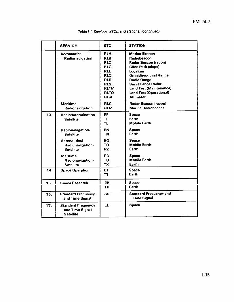
FM 24-2
I-15

FM 24-2
I-4. Spectrum Designation of Frequency Table I-2 shows that spectrum designation offrequency is a method of referring to a range or band of
communications frequencies. In America, the designatoris a two- or three-letter abbreviation for the name. In theITU, the designator is numeric.
I-16

FM 24-2
Appendix J
The Joint Restricted Frequency List
J-1. General
The JRFL is a management tool designed to minimizefrequency conflicts between friendly communica-tions/noncommunications emitters and friendly jammingequipment. More specifically, the JRFL is a time andgeographical listing of prioritized frequencies essential tothe conduct of the battle and restricted from targeting byfriendly ECM. Consisting of taboo, guarded, and protectedfrequencies, the JRFL assists staff members involved inspectrum management.
J-2. Purpose
The JRFL is constructed and maintained throughoutthe battle to graphically depict the commander’s prioritiesfor electromagnetic spectrum use. It displays to the staffand operational forces the frequencies guarded for signalintelligence (SIGINT) use or restricted from friendlyjamming due to criticality of friendly operations.Candidate nodes/nets are submitted for ECM protectionof the Joint Communications-Electronics Warfare System.This submission includes net designation, frequency, typeequipment, type modulation, location, time period, and ashort justification. Figure J-1 shows an example of a JRFL.
J-3. Definitions
Taboo frequencies are any friendly functions/frequen-
cies of such importance that they must never be deliberate-ly jammed or interfered with by friendly forces. Thesefunctions/frequencies include international distress, stopbuzzer, safety, and controller frequencies. These func-tions/frequencies are generally long-standing; however,they can be time-oriented, in that, as the combat/exercisesituation changes, the restriction can be removed by theoriginating headquarters.
Protected functions/frequencies are those friendlyfunctions/frequencies used for a particular operation,identified and protected to prevent them from beinginadvertently jammed by friendly forces while active EWoperations are directed against hostile forces. Thefunctions/frequencies are of such critical importance thatjamming is restricted unless absolutely necessary or untilcoordination with the using unit is made. They aretime-oriented, can change with the tactical situation, andare updated periodically.
Guarded functions/frequencies are enemyfunctions/frequencies that are currently being exploited forcombat information and intelligence. A guardedfunction/frequency is time-oriented, in that the list changesas the enemy assumes different combat postures. Thesefunctions/frequencies can be jammed after the commanderhas weighed the potential operational gain against the lossof technical and tactical information.
J-1


G l o s s a r y - 5


FM 24-2
References
SOURCES USEDThese are the sources quoted or paraphrased in
this publication.International and National RegulationsRadio Regulations, Published by ITU, Geneva.
1982 Edition.Manual of Regulations and Procedures for Federal
Radio Frequency Management, USDepartment of Commerce, National Telecom-munications and Information Administration.Washington, DC 20230. 30 May 1986.
Quadripartite Standardization Agreements(QSTAG)QSTAG 679. Millimeter Waves and Lasers (30
GHz and above). 25 November 1985.QSTAG 715. Battlefield Spectrum Management
HF (1.5 - 30 MHz Band). 21 May 1985.QSTAG 716. Battlefield Spectrum Management
VHF (30 - 88 MHz Band). 25 July 1985.QSTAG 718. Battlefield Spectrum Management
UHF (225 - 400 MHz Band). 05 June 1985.QSTAG 719. Battlefield Spectrum Management
Tactical Radio Relay and TroposphericScatter Systems. 19 August 1985.
QSTAG 721. Battlefield Spectrum Management:Radar, Position Navigation, TacticalSensor System and Multifunction Infor-mation Distribution System. 19 August 1985.
QSTAG 723. Battlefield Spectrum Management:Deconfliction. 20 June 1985.
Standardization Agreement (STANAG)STANAG 6004. MIJI Reporting. 28 March 1984.
DOCUMENTS NEEDED These documents must be available to the
intended users of this publication.Allied Communications Publication (ACP) *ACP 125 US Supp-1. Communications Instructions
Radiotelephone Procedures For Use by UnitedStates Ground Forces. 01 November 1985.
ACP 190 US Supp - 1(B). Guide to FrequencyPlanning. 01 October 1977.
ACP 191A. Ionospheric Sounder Operations.August 1987.
Army Regulations (ARs)*AR 5-12. Army Management of the Electro-
magnetic Spectrum. 15 May 1983.*AR 105-3. Reporting Meaconing, Intrusion,
Jamming and Interference of Electromag-netic Systems. 31 July 1986.
AR 105-24. Radio Frequency and Call SignAssignments for US Army Communications-Electronics Activities. 28 March 1977.
AR 105-86. Performing Electronic Countermeasuresin the United States and Canada.August 1983.
Field Manuals (FMs)*FM 11-32. Combat Net Radio Operations.
15 October 1990.*FM 11-50. Combat Communications Within the
Division (Heavy and Light). 04 April 1991.*FM 11-92 (HTF). Combat Communications Within
the Corps (How to Fight). 01 November 1978.FM 24-1. Signal Support in the AirLand Battle.
15 October 1990.FM 24-11. Tactical Satellite Communications.
20 September 1990.*FM 24-16. Communications-Electronics:
Operations, Orders, Records, and Reports.07 April 1978.
*FM 24-33. Communications Techniques: ElectronicCounter-Countermeasures. 17 July 1990.
*FM 24-35. Signal Operation Instructions The“SOI.” 26 October 1990.
*This source was also used to develop thispublication.
References-1

FM 24-2
Forms Joint Chiefs of Staff Publication (JCS)DA Form 2028. Recommended Changes to Publi-
cations and Blank Forms. February 1974.DD Form 1494. Application for Equipment Fre-
quency Allocation. February 1987.
READINGS RECOMMENDEDThese readings contain relevant supplemental
information.Department of Defense Directive (DOD)DOD Directive 4650.1. Management and Use of
the Radio Frequency Spectrum.December 1974.
Field Manuals (FM)FM 11-23. Theater Communications Command
(Army). 28 November 1972.FM 11-65. High Frequency Radio Communica-
tions. 31 October 1978.
JCS PUB 1-02. Department of Defense Dictionaryof Military and Associated Terms.01 June 1987.
Office of Management and Budget Circular (OMB)*OMB Circular A-11. Preparation and Submission
of Budget Estimates. July 1990.TRADOC Pamplet (PAM)TRADOC Pam 525-23. US Army Operational
Concept for Army Tactical BattlefieldSpectrum Management (ATDO).18 February 1983.
Technical Manual (TM)TM 11-5800-213-L. List of Applicable Publications
(LOAP) for Communications ElectronicEquipment. 01 October 1986.
*This source was also used to develop thispublication.
References-2