fm1100 advanced sample user guide - gps-vehicle.com€¦ · fm1100 advanced sample user guide 1...
TRANSCRIPT
1
FM1100 Advanced Sample User Guide
1 About the document
This document contains information about testing the FM1100 samples and configurations commonly used in such cases.
1.1 Login to TAVL application
TAVL application is used for users to be able to see the AVL data such as GPS location, speed,
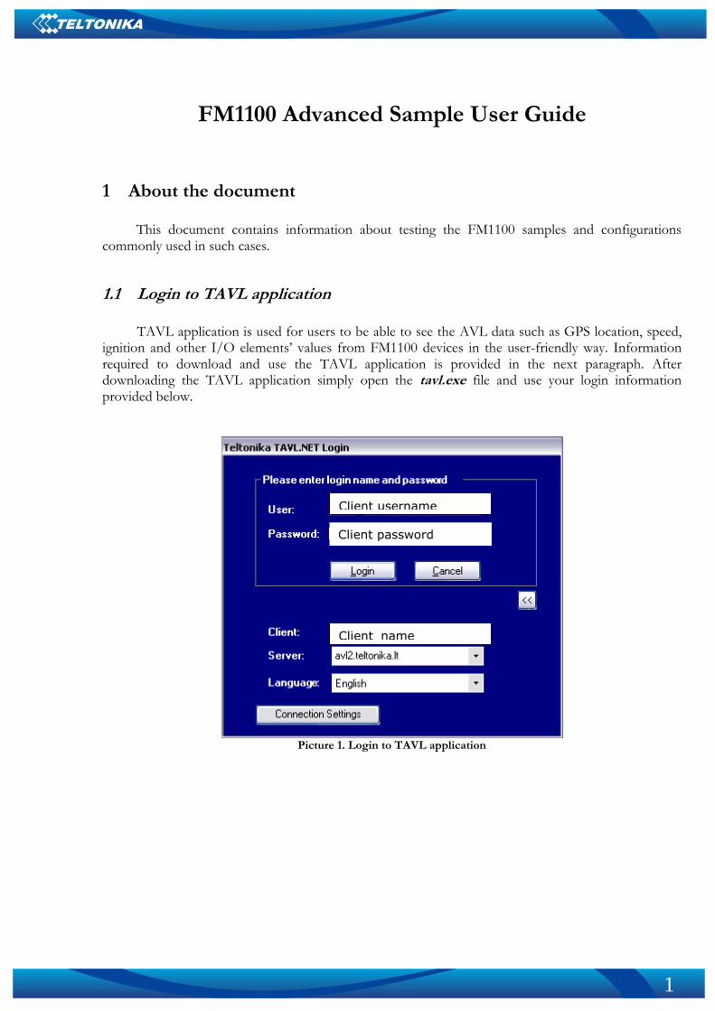
ignition and other I/O elements’ values from FM1100 devices in the user-friendly way. Information required to download and use the TAVL application is provided in the next paragraph. After downloading the TAVL application simply open the tavl.exe file and use your login information provided below.
Picture 1. Login to TAVL application
Client username
Client password
Client_name
2
1.2 Downloading the TAVL application
1.2.1 PC requirements
TAVL application runs on a PC with MS Windows XP or MS Windows Vista with latest service
packs. MS .NET Framework v3.5 SP1 and Crystal Reports are also necessary components. TAVL application supports MS MapPoint (copyright © 2008 Microsoft) or any MapX
(copyright © 2008 MapInfo Corporation) maps (additional maps have to be installed on users PC).
1.2.2 .NET Framework installation
Download .NET Framework 3.5 SP1 from Microsoft website and install it ( url:
http://www.microsoft.com/downloads/thankyou.aspx?familyId=ab99342f-5d1a-413d-8319-81da479ab0d7&displayLang=en, mirror: http://avl1.teltonika.lt/downloads/tavl/Framework/dotnetfx35setupSP1.zip ). If the download doesn't start automatically, click on the "Start Download" button.
1.2.3 Crystal Reports installation
Download and install Crystal Reports for .NET Framework ( url:
http://avl1.teltonika.lt/downloads/tavl/Crystal%20Reports/CRRedist2005_x86.zip ).
1.2.4 TAVL application installation
Downloads and extract latest available version of TAVL application ( url:
http://avl1.teltonika.lt/Downloads/tavl ).
Note , that if any additional information about the usage of the TAVL application is needed, please see the latest „TAVL3 Application User Manual“.
3
2 Getting started with FM1100 device
This paragraph contains the information needed to successfully launch and use the FM1100
device. The steps below should be followed carefully to completely test the FM100.
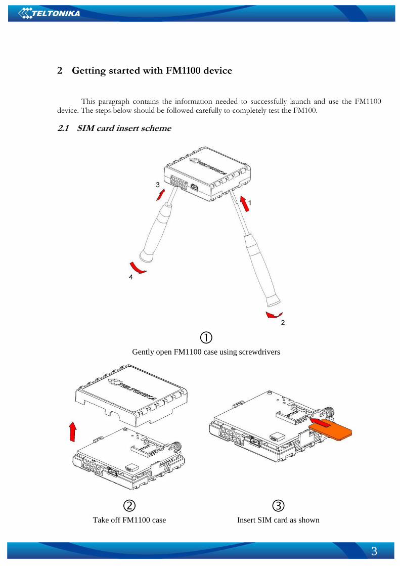
2.1 SIM card insert scheme
Gently open FM1100 case using screwdrivers
Take off FM1100 case
Insert SIM card as shown
4
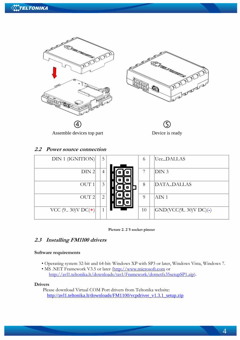
Assemble devices top part
Device is ready
2.2 Power source connection
Picture 2. 2´5 socket pinout
2.3 Installing FM1100 drivers
Software requirements
• Operating system 32-bit and 64-bit: Windows XP with SP3 or later, Windows Vista, Windows 7. • MS .NET Framework V3.5 or later (http://www.microsoft.com or
http://avl1.teltonika.lt/downloads/tavl/Framework/dotnetfx35setupSP1.zip).
Drivers Please download Virtual COM Port drivers from Teltonika website:
http://avl1.teltonika.lt/downloads/FM1100/vcpdriver_v1.3.1_setup.zip
DIN 1 (IGNITION) 5
6 Ucc_DALLAS
DIN 2 4 7 DIN 3
OUT 1 3 8 DATA_DALLAS
OUT 2 2 9 AIN 1
VCC (9 30)V DC(+) 1 10 GND(VCC(9 30)V DC)(-)
5
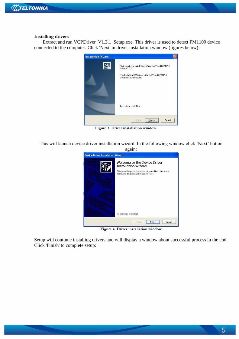
Installing drivers
Extract and run VCPDriver_V1.3.1_Setup.exe. This driver is used to detect FM1100 device
connected to the computer. Click 'Next' in driver installation window (figures below):
Figure 3. Driver installation window
This will launch device driver installation wizard. In the following window click ‘Next’ button
again:
Figure 4. Driver installation window
Setup will continue installing drivers and will display a window about successful process in the end.
Click 'Finish' to complete setup:
6
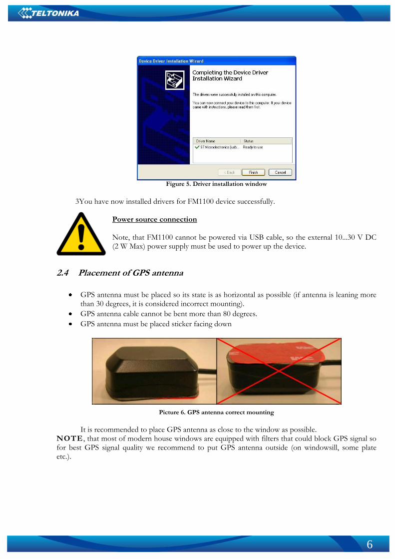
Figure 5. Driver installation window
3You have now installed drivers for FM1100 device successfully.
Power source connection Note, that FM1100 cannot be powered via USB cable, so the external 10...30 V DC (2 W Max) power supply must be used to power up the device.
2.4 Placement of GPS antenna
GPS antenna must be placed so its state is as horizontal as possible (if antenna is leaning more than 30 degrees, it is considered incorrect mounting).
GPS antenna cable cannot be bent more than 80 degrees.
GPS antenna must be placed sticker facing down
Picture 6. GPS antenna correct mounting
It is recommended to place GPS antenna as close to the window as possible.
NOTE , that most of modern house windows are equipped with filters that could block GPS signal so for best GPS signal quality we recommend to put GPS antenna outside (on windowsill, some plate etc.).
7
2.5 Loading the Configuration into the FM1100 Device
FM1100 Configurator must be used to configure the FM1100 device. Using the configurator
prepared Sample Configurations can be uploaded into the FM1100 or custom device configuration can be made.
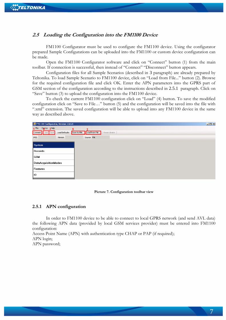
Open the FM1100 Configurator software and click on “Connect” button (1) from the main toolbar. If connection is successful, then instead of “Connect” “Disconnect” button appears.
Configuration files for all Sample Scenarios (described in 3 paragraph) are already prepared by Teltonika. To load Sample Scenario to FM1100 device, click on “Load from File...” button (2). Browse for the required configuration file and click OK. Enter the APN parameters into the GPRS part of
GSM section of the configuration according to the instructions described in 2.5.1 paragraph. Click on “Save” button (3) to upload the configuration into the FM1100 device.
To check the current FM1100 configuration click on “Load” (4) button. To save the modified configuration click on “Save to File…” button (5) and the configuration will be saved into the file with “.xml” extension. The saved configuration will be able to upload into any FM1100 device in the same way as described above.
Picture 7. Configuration toolbar view
2.5.1 APN configuration
In order to FM1100 device to be able to connect to local GPRS network (and send AVL data)
the following APN data (provided by local GSM services provider) must be entered into FM1100 configuration: Access Point Name (APN) with authentication type CHAP or PAP (if required); APN login; APN password;
8
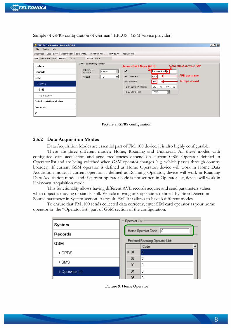
Sample of GPRS configuration of German “EPLUS” GSM service provider:
Picture 8. GPRS configuration
2.5.2 Data Acquisition Modes
Data Acquisition Modes are essential part of FM1100 device, it is also highly configurable. There are three different modes: Home, Roaming and Unknown. All these modes with
configured data acquisition and send frequencies depend on current GSM Operator defined in Operator list and are being switched when GSM operator changes (e.g. vehicle passes through country boarder). If current GSM operator is defined as Home Operator, device will work in Home Data Acquisition mode, if current operator is defined as Roaming Operator, device will work in Roaming Data Acquisition mode, and if current operator code is not written in Operator list, device will work in Unknown Acquisition mode.
This functionality allows having different AVL records acquire and send parameters values when object is moving or stands still. Vehicle moving or stop state is defined by Stop Detection Source parameter in System section. As result, FM1100 allows to have 6 different modes.
To ensure that FM1100 sends collected data correctly, enter SIM card operator as your home operator in the “Operator list” part of GSM section of the configuration.
Picture 9. Home Operator
9
3 Advanced sample scenarios
This section of the document describes the commonly used FM1100 testing scenarios and helps users to perform the detailed testing of the FM1100 device. Below you will find the descriptions of the advanced sample scenarios and the configuration for each case.
3.1 Green driving scenario
FM1100 have 2 Digital Outputs, which are manageable by 4 different scenarios. In this scenario
Digital Output 1 (DOUT1) is managed by measuring different values of GPS data.
3.1.1 Configuration
To completely test the “Green Driving” please load the prepared configuration file
“GreenDrivingScenario.xml” which has been received together with this document. Follow the
instructions in paragraph 2.5 to upload the FM1100 with the required configuration. Again the only additional configuration must be made is the APN configuration and entering
home operator code. The description of the APN configuration is described in paragraph 2.5.1, for home operator code see Picture 8.
The “Green Driving” scenario configuration is based on continuous driver behavior analysis and indication both for driver and for manager. There are 3 different parameters, which are monitored every second: acceleration, braking and angle changes. To save GPRS traffic, when one of these parameters measure value is greater than set in configuration, additional I/O event is generated and stored till periodical sending period comes.
In configuration maximal acceleration and braking forces are set to 0,4 g, which means 4 m/s acceleration or braking. If this value is reached or passed, low priority event is generated. Cornering value is set to 0,35 radians (approx. 20 degrees). There are additional requirements for these types of events to be generated: harsh acceleration and braking events can be generated if speed is >10 km/h and harsh cornering is active from >30 km/h speed.
When “Green Driving” event is generated, additional indication is available via DOUT1. DOUT1 is ON for:
3sec. if detected value is over (0; 30] % from preconfigured allowed value
5sec. if detected value is over (30; 50] % from preconfigured allowed value
7sec. if detected value is over (50; -] % from preconfigured allowed value After period of time DOUT1 is turned OFF.
“Green Driving” scenario configuration is like “City” scenario, only additional functionality is enabled. Configuration is based on fast periodic AVL data acquisition mainly according to the change of the object’s geographic angle (Min.Angle = 20 degrees). According to this configuration the FM1100 device will generate AVL record every time the object’s angle is changed more than 20 degrees. Such AVL data acquisition is rational in cases the object mostly moves in the city. Min.Distance = 200 meters, so the additional AVL record will be generated after driving more than 200 meters in the straight line. If the object with FM1100 device is not moving, the AVL data records are generated periodically every 600 seconds (Vehicle on STOP Min.period = 600 s). If the object with FM1100 device is moving, the AVL data records are generated periodically every 30 seconds.
AVL data is sent via GPRS to the server as soon as the AVL data record is generated (Min. saved records = 1; Send period = 1 s). According to this configuration one AVL data record,
10
containing information about the GPS position and Input/Output (I/O) parameters is sent to the server at least every 600 seconds.
Following I/O elements’ vales are monitored in every AVL data record:
DIN1 (as ignition) {values: 0 – Off; 1 – On};
Movement {values: 0 – object is not moving; 1 – object is moving};
Power voltage {values: from 10 V to 30 V, according to the power source).
Speed {values: current vehicle speed in km/h} Additional AVL data records called “events” are generated on following parameter value
changes:
If power voltage value falls to less than 11 V;
Speed is less than 5 km/h for more than 1 minute;
Ignition is turned ON/OFF (DIN1=1 or DIN1=0);
Green driving values are reached or passed.
3.1.2 What is the purpose of testing FM1100 in this scenario?
The main purpose of this testing scenario is for the user to understand Green Driving
functionality, which is currently available as feature only for FM1100 device. It allows to check which vehicles are not used correctly and warn their drivers. Additional DOUT1 management warns drivers as soon as such event is generated so that number of registered event would be lowered.
NOTE : Green Driving Scenario is in on various cars and various drivers testing phase and can be subject to changes. Teltonika is constantly working on improvement of the functionality of the devices, and strongly recommends using the latest version of the firmware.
3.2 “Over speeding” scenario
Another useful FM1100 testing scenario is testing the device in the “Over speeding” scenario.
Working on this scenario, FM1100 will send data as in city scenario, with additional element activated – OverSpeeding.
3.2.1 Configuration
To completely test the “Over speeding” scenario please load the prepared configuration file
“Overspeeding.xml” which was received together with this document. Again the only additional configuration must be made is the APN configuration and entering
home operator code. The description of the APN configuration is described in paragraph 2.5.1, for
home operator code see Picture 8. The “Over speeding” scenario configuration is based on fast periodic AVL data acquisition
with additional I/O element active when measured speed exceed value provided in configuration, which is 90 km/h.
According to this configuration the FM1100 device will generate AVL record every time the object’s angle is changed more than 35 degrees. Such AVL data acquisition is rational in cases the object mostly moves in highways. Min.Distance = 1000 meters, so the additional AVL record will be
11
generated after driving more than 1000 meters in the straight line. If the object with FM1100 device is not moving, the AVL data records are generated periodically every 600 seconds (Vehicle on STOP Min.period = 600 s). If the object with FM1100 device is moving, the AVL data records are generated periodically every 180 seconds. Additional event is generated, if FM1100 detects speed values greater than 90 km/h which is set in configuration.
In addition, overspeeding event manages DOUT1, so it can indicate about registered overspeeding events: when overspeeding is registered DOUT1 is ON and blinks with 300 ms duty cycle.
Following I/O elements’ vales are monitored in every AVL data record:
DIN1 (as ignition) {values: 0 – Off; 1 – On};
Movement {values: 0 – object is not moving; 1 – object is moving};
Power voltage {values: from 10 V to 30 V, according to the power source).
Speed {values: current vehicle speed in km/h} Additional AVL data records called “events” are generated on following parameter value
changes:
If power voltage value falls to less than 11 V;
Speed is less than 5 km/h for more than 1 minute;
Ignition is turned ON/OFF (DIN1=1 or DIN1=0);
Overspeeding value is passed.
3.2.2 What is the purpose of testing FM1100 in this scenario?
When vehicle is driving faster than set in Overspeeding scenario, additional low priority event will
be generated and sent to server along with periodical data. In server will be visible exact time when overspeeding occurred.
3.3 “Authorized driving” scenario
Another useful FM1100 testing scenario is testing the device in the “Authorized driving”
scenario. Working on this scenario, FM1100 will control DOUT 2 value based on read iButton ID value.
3.3.1 Configuration
To completely test the “Authorized driving” scenario please load the prepared configuration file
“Authorized driving.xml” which was received together with this document. Again additional configuration must be made is the APN configuration and entering home
operator code. The description of the APN configuration is described in paragraph 2.5.1, for home
operator code see Picture 8. Also authorized iButton list must be entered in configuration, as showed in example below. Up to 50 iButton IDs can be entered in FM1100 configuration
12
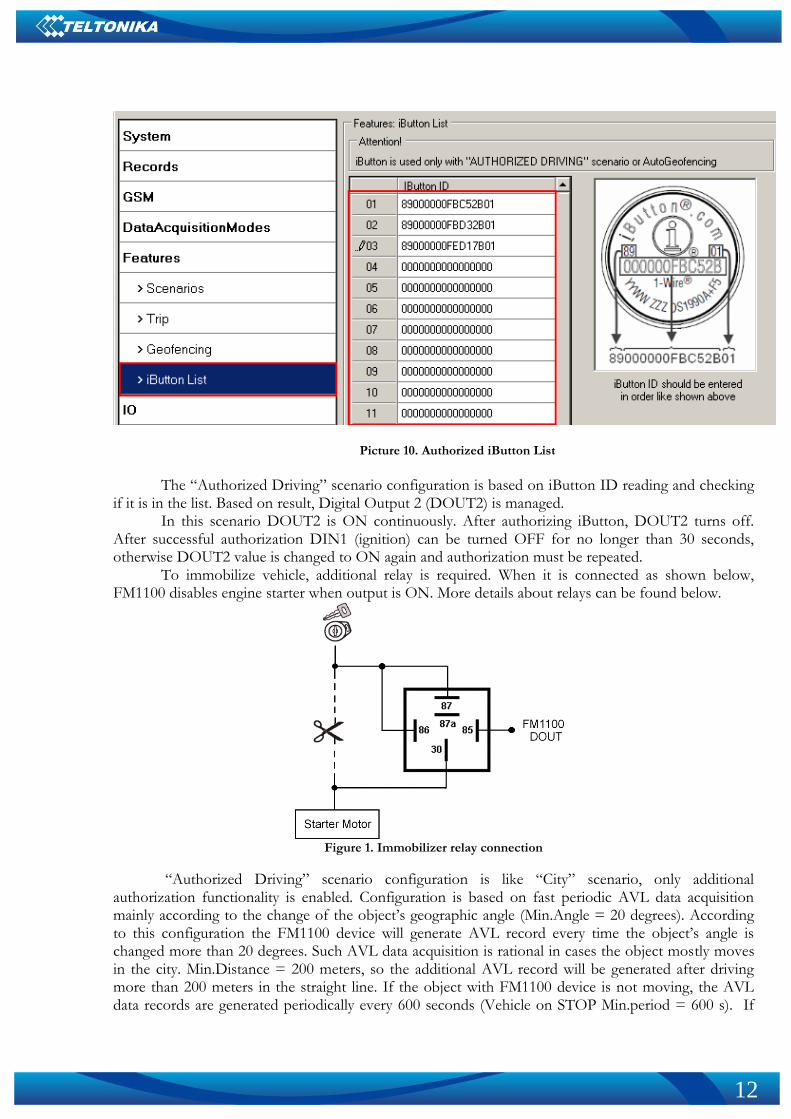
Picture 10. Authorized iButton List
The “Authorized Driving” scenario configuration is based on iButton ID reading and checking
if it is in the list. Based on result, Digital Output 2 (DOUT2) is managed. In this scenario DOUT2 is ON continuously. After authorizing iButton, DOUT2 turns off.
After successful authorization DIN1 (ignition) can be turned OFF for no longer than 30 seconds, otherwise DOUT2 value is changed to ON again and authorization must be repeated.
To immobilize vehicle, additional relay is required. When it is connected as shown below, FM1100 disables engine starter when output is ON. More details about relays can be found below.
Figure 1. Immobilizer relay connection
“Authorized Driving” scenario configuration is like “City” scenario, only additional authorization functionality is enabled. Configuration is based on fast periodic AVL data acquisition mainly according to the change of the object’s geographic angle (Min.Angle = 20 degrees). According to this configuration the FM1100 device will generate AVL record every time the object’s angle is changed more than 20 degrees. Such AVL data acquisition is rational in cases the object mostly moves in the city. Min.Distance = 200 meters, so the additional AVL record will be generated after driving more than 200 meters in the straight line. If the object with FM1100 device is not moving, the AVL data records are generated periodically every 600 seconds (Vehicle on STOP Min.period = 600 s). If
13
the object with FM1100 device is moving, the AVL data records are generated periodically every 30 seconds.
AVL data is sent via GPRS to the server as soon as the AVL data record is generated (Min. saved records = 1; Send period = 1 s). According to this configuration one AVL data record, containing information about the GPS position and Input/Output (I/O) parameters is sent to the server at least every 600 seconds.
Following I/O elements’ vales are monitored in every AVL data record:
DIN1 (as ignition) {values: 0 – Off; 1 – On};
Movement {values: 0 – object is not moving; 1 – object is moving};
Power voltage {values: from 10 V to 30 V, according to the power source).
Speed {values: current vehicle speed in km/h}
iButton {values: read iButton ID} Additional AVL data records called “events” are generated on following parameter value
changes:
If power voltage value falls to less than 11 V;
Speed is less than 5 km/h for more than 1 minute;
Ignition is turned ON/OFF (DIN1=1 or DIN1=0);
iButton ID is read
3.3.2 What is the purpose of testing FM1100 in this scenario?
When DOUT2 is connected to relay as showed in figure 11, before authorization vehicle engine
will not be able to start. After iButton ID is read and it is found in authorized iButton list, DOUT2 value will be changed to 0 and engine could be started.
3.4 “Immobilizer” scenario
Another useful FM1100 testing scenario is testing the device in the “Over speeding” scenario.
Working on this scenario, FM1100 will send data as in city scenario, with additional element activated – OverSpeeding.
3.4.1 Configuration
To completely test the “Over speeding” scenario please load the prepared configuration file
“Immobilizer.xml” which was received together with this document. Only additional configuration must be made is the APN configuration and entering home
operator code. The description of the APN configuration is described in paragraph 2.5.1, for home
operator code see Picture 8. Also additional connection of automotive relay is required, which is displayed in Picture 11.
The “Immobilizer” scenario configuration is based on DOUT2 managing accordingly to iButton. In this scenario there is no authentication list – any read iButton ID will switch DOUT2 state, and allow to activate ignition. DOUT2 is managed in such scenario:
While iButton ID is not read and DIN1 is ON, DOUT2 is ON continuously then after 1 minute it starts to blink with 300 ms duty cycle. DOUT2 turns OFF, after iButton is connected. After
14
successful deactivation of immobilizer DIN1 (ignition) can be turned OFF for no longer than 30 seconds, otherwise Immobilizer security will be turned on and deactivation must be repeated.
“Immobilizer” scenario configuration is like “City” scenario, only additional authorization functionality is enabled. Configuration is based on fast periodic AVL data acquisition mainly according to the change of the object’s geographic angle (Min.Angle = 20 degrees). According to this configuration the FM1100 device will generate AVL record every time the object’s angle is changed more than 20 degrees. Such AVL data acquisition is rational in cases the object mostly moves in the city. Min.Distance = 200 meters, so the additional AVL record will be generated after driving more than 200 meters in the straight line. If the object with FM1100 device is not moving, the AVL data records are generated periodically every 600 seconds (Vehicle on STOP Min.period = 600 s). If the object with FM1100 device is moving, the AVL data records are generated periodically every 30 seconds.
AVL data is sent via GPRS to the server as soon as the AVL data record is generated (Min. saved records = 1; Send period = 1 s). According to this configuration one AVL data record, containing information about the GPS position and Input/Output (I/O) parameters is sent to the server at least every 600 seconds.
Following I/O elements’ vales are monitored in every AVL data record:
DIN1 (as ignition) {values: 0 – Off; 1 – On};
Movement {values: 0 – object is not moving; 1 – object is moving};
Power voltage {values: from 10 V to 30 V, according to the power source).
Speed {values: current vehicle speed in km/h}
iButton {values: read iButton ID} Additional AVL data records called “events” are generated on following parameter value
changes:
If power voltage value falls to less than 11 V;
Speed is less than 5 km/h for more than 1 minute;
Ignition is turned ON/OFF (DIN1=1 or DIN1=0);
iButton ID is read
3.4.2 What is the purpose of testing FM1100 in this scenario?
When DOUT2 is connected to relay as showed in figure 11, before iButton ID is read vehicle
engine will not be able to start: DOUT2 will be set to 1 for 1 minute after FM1100 power up, or after 30 seconds from Ignition OFF event. When 1 minute passes, DOUT will start to blink. Thus, starter can be active for a moment, and then cut off. After iButton ID is read DOUT2 value will be changed to 0 and engine could be started.
3.5 “Autogeofencing” scenario
“Autogeofencing” feature provides additional security from vehicle towing, by creating
temporary circle shaped zones with in configuration set radius, when vehicle is not moving. Stop of vehicle is monitored by Ignition value, so in order to use this scenario ignition must be connected to DIN1. Activation is done after activation timeout time have passed. Deactivation of this function can be done by two ways: authorized iButton list (if any iButton is entered into list, as showed in picture 10) or ignition (DIN1) value change.
15
3.5.1 Configuration
To completely test the “autgeofencing” please load the prepared configuration file
“AutogeofencingScenario.xml” which has been received together with this document. Follow the
instructions in paragraph 2.5 to upload the FM1100 with the required configuration. Additional configuration must be made: APN configuration and enter home operator code.
The description of the APN configuration is described in paragraph 2.5.1, for home operator code see Picture 8.
The “Autogeofencing” scenario configuration is based ignition checking, so DIN1 must be connected to ignition. For “autogeofencing” feature to be active, GPS satellites must be visible. Zone radius is set to 250 meters around the middle coordinate, where vehicle will be standing.
In configuration priority of event is set to high, so that generated record would be sent immediately after event occurred. Generation of event is set to “on exit”, so that event record would be generated and sent to server only if vehicle has left the zone without Ignition value turned ON.
“Autogeofencing” scenario configuration is like “City” scenario, only additional functionality is enabled. Configuration is based on fast periodic AVL data acquisition mainly according to the change of the object’s geographic angle (Min.Angle = 20 degrees). According to this configuration the FM1100 device will generate AVL record every time the object’s angle is changed more than 20 degrees. Such AVL data acquisition is rational in cases the object mostly moves in the city. Min.Distance = 200 meters, so the additional AVL record will be generated after driving more than 200 meters in the straight line. If the object with FM1100 device is not moving, the AVL data records are generated periodically every 600 seconds (Vehicle on STOP Min.period = 600 s). If the object with FM1100 device is moving, the AVL data records are generated periodically every 30 seconds.
AVL data is sent via GPRS to the server as soon as the AVL data record is generated (Min. saved records = 1; Send period = 1 s). According to this configuration one AVL data record, containing information about the GPS position and Input/Output (I/O) parameters is sent to the server at least every 600 seconds.
Following I/O elements’ vales are monitored in every AVL data record:
DIN1 (as ignition) {values: 0 – Off; 1 – On};
Movement {values: 0 – object is not moving; 1 – object is moving};
Power voltage {values: from 10 V to 30 V, according to the power source).
Speed {values: current vehicle speed in km/h} Additional AVL data records called “events” are generated on following parameter value
changes:
If power voltage value falls to less than 11 V;
Speed is less than 5 km/h for more than 1 minute;
Ignition is turned ON/OFF (DIN1=1 or DIN1=0);
Green driving values are reached or passed.
3.5.2 What is the purpose of testing FM1100 in this scenario?
When vehicle have turned OFF engine (ignition) and it was not turned ON again in 60 seconds,
autogeofence is activated . If vehicle would be towed (with Igniton OFF) for at least 260 meters, high priority event would be generated and sent to server immeadiately. Autogeofence is deactivated by ignition (if ignition is ON).

16
Note , that if any additional information about the configuration or working of the FM1100 device is needed, please see the latest „FM1100 User Manual“.