fm9400 front mount - fast ag solutions · electrocution can occur without direct contact. 9. read...
TRANSCRIPT

FRONT MOUNTCENTER PIVOT
SUSPENDED BOOMFIELD SPRAYERFM9400 SERIES
OPERATOR'S MANUAL

LIMITED WARRANTY
Fast Distributing Inc. warrants to the buyer that the new machinery is free from defects inmaterial and workmanship.
This warranty is only effective as to any new machinery which has not been altered,changed, repaired or treated since its delivery to the buyer, other than by Fast Distributingor its authorized dealers or employees, and does not apply to accessories, attachments,tools or parts, sold or operated with the new machinery, if they have not been manufacturedby Fast Distributing.
Fast Distributing shall only be liable for defects in the materials or workmanship attributableto faulty material or bad workmanship that can be proved by the buyer, and specificallyexcludes liability for repairs arising as a result of normal wear and tear of the new machineryor in any other manner whatsoever, and without limiting the generality of the foregoing,excludes application or installation of parts not completed in accordance with FastDistributing operator's manual, specifications, or printed instructions.
Written notice shall be given by registered mail, to Fast Distributing within seven (7) daysafter the defect shall have become apparent or the repairs shall have become necessary,addressed as follows: Fast Distributing Inc. 54859 County Road 44, Mountain Lake, MN56159.
This warranty shall expire two (2) years after the date of delivery of the new machinery.
If these conditions are fulfilled, Fast shall at its own cost and at its own option either repairor replace any defective parts provided that the buyer shall be responsible for all expensesincurred as a result of repairs, labour, parts, transportation or any other work, unless Fasthas authorized such expenses in advance.
The warranty shall not extend to any repairs, changes, alterations, or replacements madeto the new equipment other than by Fast or its authorized dealers or employees.
This warranty extends only to the original owner of the new equipment.
Rubber parts are not warranted. (including tires, hoses, grommets)
This warranty is limited to the terms stated herein and is in lieu of any other warrantieswhether express or implied, and without limiting the generality of the foregoing, excludedall warranties, express or implied or conditions whether statutory or otherwise as to qualityand fitness for any purpose of the new equipment. Fast disclaims all liability for incidentalor consequential damages.
This sprayer is subject to design changes and Fast Distributing Inc. shall not be requiredto retro-fit or exchange items on previously sold units except at its own option.
Fast Distributing Inc.

SERIAL NUMBER LOCATION
Always give your dealer the serial number of your Fast Distributing Front Mount Center Pivot High-Clearance Suspended Boom Field Sprayer when ordering parts or requesting service or other information.
The serial number is stamped on a serial tag attached to the center section frame where indicated. Pleasemark the number in the space provided for easy reference.
Model Number FM9400
Sprayer Serial Number FM9400 _ _ _ _ _ _ _

TABLE OF CONTENTS
SECTION DESCRIPTIONPAGE
1 Introduction ............................................................. 12 Safety ................................................................... 2 2.1 General Safety ...................................................... 3 2.2 Operating Safety ................................................... 4 2.3 Chemical Safety ................................................... 5 2.4 Maintenance Safety .............................................. 6 2.5 Hydraulic Safety ................................................... 6 2.6 Transport Safety ................................................... 7 2.7 Tire Safety ............................................................ 7 2.8 Storage Safety ...................................................... 7 2.9 Safety Signs ......................................................... 7 2.10 Sign-Off Form ....................................................... 83 Safety Sign Locations ........................................ 94 Operation ........................................................... 13 4.1 To the New Operator or Owner ........................... 13 4.2 Machine Components ......................................... 14 4.3 Break-In .............................................................. 15 4.4 Pre-Operation Checklist ...................................... 15 4.5 Equipment Matching ........................................... 16 4.6 Controls .............................................................. 18 4.7 Installing Controllers ........................................... 23 4.8 Attaching/Unhooking Tractor .............................. 24 4.9 Sprayer Calibration ............................................. 27 4.9.1 Engine RPM ....................................................... 27 4.9.2 Controller Calibration.......................................... 28 4.9.3 Nozzle Calibration .............................................. 28 4.9.4 Machine Yard Calibration ................................... 30 4.9.5 Ground Speed Calibration .................................. 30 4.9.6 Area Covered ..................................................... 32 4.9.7 Field Calibration ................................................. 32 4.10 Field Operation ................................................... 33 4.11 Transport/Field Conversion ................................ 44 4.12 Transport ............................................................ 46 4.13 Storage ............................................................... 47 4.13.1 Placing In Storage .............................................. 47 4.13.2 Removing From Storage ..................................... 485 Service and Maintenance ................................. 49 5.1 Service................................................................ 49 5.1.1 Fluids and Lubricants ......................................... 49 5.1.2 Greasing......................................................................49
5.1.2.1 Mounting hardware....................................................49 5.1.3 Servicing Intervals .............................................. 50 5.1.4 Service Record ................................................... 55 5.2 Maintenance ....................................................... 56

SECTION DESCRIPTIONPAGE
5.2.1 Filter Cleaning .................................................... 56 5.2.2 Tank Cleaning .................................................... 57 5.2.3 Boom Break-Aways ............................................ 57 5.2.4 Boom Straightness ............................................. 596 Trouble Shooting .............................................. 637 Specifications ................................................... 64 7.1 Mechanical ......................................................... 64 7.2 Bolt Torque ......................................................... 64 7.3 Hydraulic Fitting Torque ..................................... 64 7.4 Chemical Circuit Schematic................................ 65 7.5 Electrical Schematic ........................................... 67 7.6 5 Function Hydraulic Block Parts ........................ 68 7.7 5 Function Hydraulic Cab Box ............................ 69 7.8 5 Function Hydraulic Cab Box Switch Wiring ..... 70 7.9 Optional 7 Function Hydraulic Block................... 71 7.10 7 Optional Function Hydraulic Cab Box.............. 72 7.11 7 Function Hydraulic Cab Box Switch Wiring ..... 738 Index .................................................................. 74

1
1 INTRODUCTION
Congratulations on your choice of a Fast Distributing FM9400 Series Center Pivot High-ClearanceSuspended Boom Field Sprayer to complement your farming operation. This equipment has beendesigned and manufactured to meet the needs of a discriminating buyer for the efficient spraying ofcrops.
Safe, efficient and trouble free operation of your Fast Distributing Field Sprayer requires that you andanyone else who will be operating or maintaining the Sprayer, read and understand the Safety, Opera-tion, Maintenance and Trouble Shooting information contained in the Operator's Manual.
This manual covers FM9400 Series Center Pivot High-Clearance Suspended Boom Field Sprayers built byFast Distributing. Use the Table of Contents or Index as a guide when searching for specific information.
Keep this manual handy for frequent reference and to pass on to new operators or owners. Call yourFast dealer or distributor if you need assistance or information.
OPERATOR ORIENTATION - The directions left, right, front and rear, as mentioned throughout thismanual, are as seen from the tractor driver's seat and facing in the direction of travel.

Accidents Disable and KillAccidents CostAccidents Can Be Avoided
3 Big Reasons
2 SAFETY
SAFETY ALERT SYMBOL
SIGNAL WORDS:Note the use of the signal words DANGER,WARNING and CAUTION with the safetymessages. The appropriate signal word foreach message has been selected using thefollowing guide-lines:
situation that, if not avoided, will resultin death or serious injury. This signalword is to be limited to the mostextreme situations, typically for ma-chine components that, for functionalpurposes, cannot be guarded.
Indicates a potentially hazardoussituation that, if not avoided, couldresult in death or serious injury, andincludes hazards that are exposedwhen guards are removed. It mayalso be used to alert against unsafepractices.
Indicates a potentially hazardoussituation that, if not avoided, mayresult in minor or moderate injury. Itmay also be used to alert againstunsafe practices.
DANGER - Indicates an imminently hazardous
WARNING -
CAUTION -
The Safety Alert symbol identifiesimportant safety messages on theFast Distributing Center Pivot High-Clearance Suspended Boom FieldSprayer and in the manual. Whenyou see this symbol, be alert to thepossibility of personal injury ordeath. Follow the instructions in thesafety message.
This Safety Alert symbol meansATTENTION! BECOME ALERT!YOUR SAFETY IS INVOLVED!
Why is SAFETY important to you?
2
If you have any questions not answered in this manual or require additional copies or the manual isdamaged, please contact your dealer or Fast Distributing Inc., 54859 County Road 44, Mountain Lake,MN 56159, (Telephone) 507-427-3861, (FAX) 507-427-3030.

2.1 GENERAL SAFETYSAFETY
YOU are responsible for the SAFE operation andmaintenance of your Fast Distributing CenterPivot High-Clearance Suspended Boom FieldSprayer. YOU must ensure that you and anyoneelse who is going to operate, maintain or workaround the Sprayer be familiar with the operatingand maintenance procedures and relatedSAFETY information contained in this manual.This manual will take you step-by-step throughyour working day and alerts you to all good safetypractices that should be adhered to while operat-ing the Sprayer.
Remember, YOU are the key to safety. Goodsafety practices not only protect you but also thepeople around you. Make these practices aworking part of your safety program. Be certainthat EVERYONE operating this equipment isfamiliar with the recommended operating andmaintenance procedures and follows all the safetyprecautions. Most accidents can be prevented. Donot risk injury or death by ignoring good safetypractices.
• Sprayer owners must give operating instruc-tions to operators or employees beforeallowing them to operate the Sprayer, and atleast annually thereafter per OSHA regulation1928.57.
• The most important safety feature on thisequipment is a SAFE operator. It is theoperator’s responsibility to read and under-stand ALL Safety and Operating instructionsin the manual and to follow these. All acci-dents can be avoided.
• A person who has not read and understood alloperating and safety instructions is not quali-fied to operate the machine. An untrainedoperator exposes himself and bystanders topossible serious injury or death.
• Do not modify the equipment in any way.Unauthorized modification may impair thefunction and/or safety and could affect the lifeof the equipment.
• Think SAFETY! Work SAFELY!
1. Read and understand theOperator’s Manual and allsafety signs before operating,maintaining or adjusting theSprayer.
3
2. Only trained competent persons shall operatethe Sprayer. An untrained operator is notqualified to operate the machine.
- A hard hat- Rubber boots- Protective goggles- Neoprene gloves- Water repellent
clothing- Respirator or filter
mask
6. Place all controls in neutral, stop tractorengine, turn monitor off, set park brake,remove ignition key, wait for nozzles to stopspraying before servicing, adjusting, repairingor unplugging.
7. Read chemical manufacturers warnings,instructions and procedures before startingand follow them exactly.
8. Post Poison Control Emergency telephonenumber for your area on sprayer before usingAgricultural chemicals.
Ottawa: (613) 992-5606Washington DC: (202) 962-4525
Have container label handy when seekingmedical attention.
9. Review safety related items with all personnelannually.
3. Have a first-aid kit available foruse should the need arise andknow how to use it.
5. Wear appropriate protectivegear. This list includes but isnot limited to:
4. Do not allow riders.
4
2.2 OPERATING SAFETY
1. Read and understand the Operator’s Manualand all safety signs before using.
2. Place all controls in neutral, stop tractorengine, turn monitor off, set park brake,remove ignition key, wait for nozzles to stopspraying before servicing, adjusting, repairingor unplugging.
3. Before spraying a field, be familiar with allpotential hazards: trees, rocks, ditches,gullies, etc. Plan the spraying route to avoidhazards. Remember you are driving a widemachine. USE CAUTION WHEN CORNER-ING.
4. Keep hands, feet, hair and clothing away fromall moving and/or rotating parts.
5. Do not allow riders on the sprayer or tractorduring operation or transporting.
6. Clear the area of all bystanders, especiallychildren, before starting or filling with water orchemical.
7. Stay away from wing pinch points whenfolding or extending wings. Keep othersaway.
8. Stay away from power lines when extendingor folding wings. Electrocution can occurwithout direct contact.
9. Read chemical manufacturers warnings,instructions and procedures before startingand follow them exactly.
10. Do not breathe, touch or ingest chemicals.Always wear protective clothing and followsafe handling procedures.
11. Spray only when potential for chemical drift isat a minimum. Even small amounts can affectneighboring crops or sensitive plants andpeople.
12. Dispose of chemical containers by triplerinsing them into the sprayer tank or thor-oughly rinsing, crushing and delivering toregional disposal site.
13. In case of poisoning, get immediate medicalattention.
14. Only rinse sprayer while still in the field.Spray the rinse thinly over the field alreadysprayed. Never contaminate the farmyard ordrainage systems with sprayer rinse.
15. Do not eat in the field when spraying.
16. Before applying pressure to the hydraulicsystem, make sure all components are tightand that steel lines, hoses and couplings arein good condition.
17. Before applying pressure to chemical systemmake sure that all connections are tight andthat all hoses and fittings are in good condi-tion.
18. Review safety instructions annually.

2.3 CHEMICAL SAFETY
1. Some Agricultural chemicals are among themost toxic substances known to man. Minutequantities can contaminate clothing, machin-ery, the workplace and the environment.Follow the chemical manufacturers' instruc-tions exactly. Death can result from theirimproper use.
2. Misuse, including excessive rates, unevenapplication, wind drift, and label violations cancause injury to crops, livestock, persons andthe environment.
3. Do not breathe, touch or ingest chemicals,Always wear protective clothing and followsafe handling procedures.
4. Follow the manufacturers' instructions forchemical storage. Avoid unnecessary storageby purchasing only the quantity needed for thecrop year.
5. Keep all chemicals out of reach of childrenand away from livestock and animals.
6. Store chemicals only in their original contain-ers and in a locked area.
7. Check with state environment departmentregarding the disposal of small quantities ofchemicals, chemical containers and washwater. Follow their disposal instructions.
8. Do not burn the containers or leave them lyingin the field or ditches. Dispose of them bytriple rinsing and leaving at a pesticide con-tainer disposal site.
9. Wash thoroughly before eating. Use a deter-gent to remove all chemical residue. Rinsecarefully and dry with disposable towels.
10. Do not eat in the field when spraying.
11. In case of chemical poisoning, get immediatemedical attention. Have container label handywhen seeking medical attention.
12. Post Poison Control Emergency telephonenumber for your area on sprayer before usingAgricultural chemicals.
Ottawa: (613) 992-5606Washington DC: (202) 962-4525
Have container label handy when seekingmedical attention.
13. Thoroughly wash clothing and equipmentcontaminated by chemicals.
14. Do not allow children or workers on contami-nated sprayer.
15. Rinse sprayer while still in the field. Spray therinse thinly over the field already sprayed.Never contaminate the farmyard or drainagesystems with sprayer rinse.
16. Do not use the sprayer to transport drinkingwater.
17. Wash down the Sprayer immediately afterfield work. Dispose of the wash water in anenvironmentally safe manner. Wash watercan contaminate the soil or a clean watersupply.
5
6
2.4 MAINTENANCE SAFETY
1. Review the Operator's Manual and all safetyitems before working with, maintaining oroperating the Sprayer.
2. Place all controls in neutral, stop the tractorengine, turn monitor off, set park brake,remove ignition key, wait for nozzles to stopspraying before servicing, adjusting, repairingor unplugging.
2.5 HYDRAULIC SAFETY
1. Always place all tractor hydraulic controls inneutral before dismounting.
2. Make sure that all components in the hydrau-lic system are kept in good condition and areclean.
3. Replace any worn, cut, abraded, flattened or crimped hoses and steel lines.
4. Do not attempt any makeshift repairs to thehydraulic lines, fittings or hoses by using tape,clamps or cements. The hydraulic systemoperates under extremely high-pressure.Such repairs will fail suddenly and create ahazardous and unsafe condition.
6. If injured by a concentrated high-pressurestream of hydraulic fluid, seek medical atten-tion immediately. Serious infection or toxicreaction can develop from hydraulic fluidpiercing the skin surface.
7. Before applying pressure to the system, makesure all components are tight and that lines,hoses and couplings are in good condition.
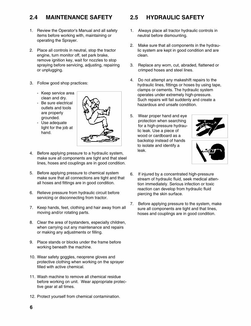
5. Wear proper hand and eye protection when searching for a high-pressure hydrau-
lic leak. Use a piece ofwood or cardboard as abackstop instead of handsto isolate and identify aleak.
3. Follow good shop practices:
- Keep service areaclean and dry.
- Be sure electricaloutlets and toolsare properlygrounded.
- Use adequatelight for the job athand.
4. Before applying pressure to a hydraulic system,make sure all components are tight and that steellines, hoses and couplings are in good condition.
5. Before applying pressure to chemical systemmake sure that all connections are tight and thatall hoses and fittings are in good condition.
6. Relieve pressure from hydraulic circuit beforeservicing or disconnecting from tractor.
7. Keep hands, feet, clothing and hair away from allmoving and/or rotating parts.
8. Clear the area of bystanders, especially children,when carrying out any maintenance and repairsor making any adjustments or filling.
9. Place stands or blocks under the frame beforeworking beneath the machine.
10. Wear safety goggles, neoprene gloves andprotective clothing when working on the sprayerfilled with active chemical.
11. Wash machine to remove all chemical residuebefore working on unit. Wear appropriate protec-tive gear at all times.
12. Protect yourself from chemical contamination.

2.6 TRANSPORT SAFETY
1. Read and understand ALL the information inthe Operator’s Manual regarding proceduresand SAFETY when operating the Sprayer in thefield and/or on the road.
2. Check with local authorities regarding sprayertransport on public roads. Obey all applicablelaws and regulations.
3. Always travel at a safe speed. Use cautionwhen making corners or meeting traffic.
4. Make sure the SMV (Slow Moving Vehicle)emblem and all the lights and reflectors that arerequired by the local highway and transportauthorities are in place, are clean and can beseen clearly by all overtaking and oncomingtraffic.
5. Be sure that the Sprayer is hitched positively tothe towing vehicle. Always use a retainerthrough the pin and a safety chain between themachine and the tractor.
6. Keep to the right and yield the right-of-way toallow faster traffic to pass. Drive on the roadshoulder, if permitted by law.
7. Do not exceed 20 mph (32 km/h). Reducespeed on rough roads and surfaces.
8. Always use hazard warning flashers on tractorwhen transporting unless prohibited by law.
9. Never transport with the tank filled with water orchemical.
7
2.7 TIRE SAFETY
1. Failure to follow proper procedures whenmounting a tire on a wheel or rim can producean explosion which may result in serious injuryor death.
2. Do not attempt to mount a tire unless you havethe proper equipment and experience to do thejob.
3. Have a qualified tire dealer or repair serviceperform required tire maintenance.
2.8 STORAGE SAFETY
1. Store unit in an area away from humanactivity.
2. Do not permit children to play on or aroundthe stored sprayer.
3. Unhook and store in the transport configura-tion.
2.9 SAFETY SIGNS
1. Keep safety signs clean and legible at alltimes.
2. Replace safety signs that are missing or havebecome illegible.
3. Replaced parts that displayed a safety signshould also display the current sign.
4. Safety signs are available from your Distribu-tor or the factory.
How to Install Safety Signs:
• Be sure that the installation area is clean anddry.
• Be sure temperature is above 50°F (10°C).
• Decide on the exact position before youremove the backing paper.
• Remove the smallest portion of the splitbacking paper.
• Align the sign over the specified area andcarefully press the small portion with theexposed sticky backing in place.
• Slowly peel back the remaining paper andcarefully smooth the remaining portion of thesign in place.
• Small air pockets can be pierced with a pinand smoothed out using the piece of signbacking paper.

8
2.10 SIGN-OFF FORM
Fast Distributing Inc. follows the general Safety Standards specified by the American Society of Agricul-tural Engineers (ASAE) and the Occupational Safety and Health Administration (OSHA). Anyone who willbe operating and/or maintaining the Fast Distributing Sprayer must read and clearly understand ALLSafety, Operating and Maintenance information presented in this manual.
Do not operate or allow anyone else to operate this equipment until such information has been reviewed.Annually review this information before the season start-up.
Make these periodic reviews of SAFETY and OPERATION a standard practice for all of your equipment.We feel that an untrained operator is unqualified to operate this machine.
A sign-off sheet is provided for your record keeping to show that all personnel who will be working withthe equipment have read and understand the information in the Operator’s Manual and have been in-structed in the operation of the equipment.
DATE EMPLOYEES SIGNATURE EMPLOYERS SIGNATURE
SIGN-OFF FORM

REMEMBER - If Safety Signs have been damaged, removed, become illegible or parts replaced withoutsafety designs, new signs must be applied. New safety signs are available from your authorized dealer.
9
3 SAFETY SIGN LOCATIONS
The types of safety signs and locations on the equipment are shown in the illustration below. Good safetyrequires that you familiarize yourself with the various Safety Decals, the type of warning and the area, orparticular function related to that area, that requires your SAFETY AWARENESS.
• Think SAFETY! Work SAFELY!
C
WARNING
To prevent serious injury or deathfrom high pressure fluid:
• Relieve pressure on system beforerepairing, adjusting or disconnecting.
• Wear proper hand and eye protectionwhen searching for leaks. Use woodor cardboard instead of hands.
• Keep all components in good repair.
HIGH-PRESSURE FLUID HAZARD
B
WARNINGInstall the safety pin and securebefore transporting sprayer.
A
CAUTION
B B
802
1. Read and understand the Operator's Manual beforeusing.
2. Read Chemical manufacturers' WARNINGS, instruc-tions and procedures before starting and follow themexactly.
3. Stop tractor engine, place all controls in neutral, setpark brake, remove ignition key and wait for allmoving parts to stop before servicing, adjusting,repairing, unplugging or filling.
4. Always wear proper eye, breathing and clothingprotection.
5. Stay away from chemicals, spray and drift. Keepothers away.
6. Install and secure all guards before starting.7. Keep hands, feet, hair and clothing away from
moving parts.8. Do not allow riders.9. Keep all chemical and hydraulic lines, fittings and
couplers tight and free of leaks before starting andoperating.
10. Stay away from overhead power lines.11. Clear the area of bystanders before extending or
folding wings.12. Release second wing extend switch before first wing.13. Hitch can upend . Do not stand over hitch when
unhooking. Support hitch and sprayer on standsbefore removing pin.
14. Review safety instructions with all operators annu-ally. 800
809
A H F

10
REMEMBER - If Safety Signs have been damaged, removed, become illegible or parts replaced withoutsafety designs, new signs must be applied. New safety signs are available from your authorized dealer.
F
TOXIC CHEMICAL HAZARD
WARNING
Agricultural chemicals can be dangerous.Improper selection or use can seriouslyinjure persons, animals, plants, soil or otherproperty. BE SAFE: Select the rightchemical for the job. Handle it with care.Follow the instructions on the containerlabel and instructions from the equipmentmanufacturer.
The types of safety signs and locations on the equipment are shown in the illustration below. Good safetyrequires that you familiarize yourself with the various Safety Decals, the type of warning and the area, orparticular function related to that area, that requires your SAFETY AWARENESS.
• Think SAFETY! Work SAFELY!
G
DANGER
ELECTROCUTION HAZARDKEEP AWAY FROM POWER LINES
1. Stay well away from power lineswhen folding or extending wings.Electrocution can occur withoutdirect contact.
2. Lower wings completely beforemoving or transporting.
To prevent serious injury or death fromelectrocution:
B
B
807
805

The types of safety signs and locations on the equipment are shown in the illustration below. Good safetyrequires that you familiarize yourself with the various Safety Decals, the type of warning and the area, orparticular function related to that area, that requires your SAFETY AWARENESS.
• Think SAFETY! Work SAFELY!
REMEMBER - If Safety Signs have been damaged, removed, become illegible or parts replaced withoutsafety designs, new signs must be applied. New safety signs are available from your authorized dealer.
11
H
WEAR RUBBERGLOVES
• Do not allowchemical orsolution to touchskin. Some canbe absorbedthrough the skin.
• Wear rubbergloves andprotective gearat all times.
CHEMICAL HAZARD
DANGER
DON'T INGESTCHEMICAL
DON'T BREATHEVAPOR
• Chemicals can be toxic.• If in eyes or mouth, read
chemical manufacturers'instructions and followthem exactly.
• Seek medical attentionimmediately.
• A poison control numberis normally inside thefront cover of yourtelephone book.
• Stay away fromchemical splashand vapor. Keepothers away.
• Do not breathevapor.
• Wear properrespirator whenworking withchemicals.
J
WARNING
OVERHEAD HAZARDKEEP AWAY
To prevent serious injury ordeath from overhead hazard:
• Stay away from machine whenextending or folding wings.
• Keep others away.• Move wings only from tractor seat.
To prevent serious injury or death:
806
808

12
REMEMBER - If Safety Signs have been damaged, removed, become illegible or parts replaced withoutsafety designs, new signs must be applied. New safety signs are available from your authorized dealer.
The types of safety signs and locations on the equipment are shown in the illustration below. Good safetyrequires that you familiarize yourself with the various Safety Decals, the type of warning and the area, orparticular function related to that area, that requires your SAFETY AWARENESS.
• Think SAFETY! Work SAFELY!
Raise boom and turn cylindervalve off before transporting orworking under the boom.
WARNINGL
L
JL
JL

13
4 OPERATION
Many features incorporated into this machine are theresult of suggestions made by customers like you.Read this manual carefully to learn how to operatethe machine safely and how to set it to providemaximum field efficiency. By following the operatinginstructions in conjunction with a good maintenanceprogram, your Sprayer will provide many years oftrouble-free service.
4.1 TO THE NEW OPERATOR OR OWNER
Todays Agricultural industry works closely with thechemical industry to develop and use the appropri-ate compound for control of insects, weeds andfungus. Effective results are closely related toapplication methods and techniques. Fast Distribut-ing Inc. has designed a field sprayer that will placethe chemicals exactly where they are needed.
It is the responsibility of the owner or operator toread this manual and the chemical containerlabel before starting. Follow all safety instruc-tions exactly. Safety is everyone's business. Byfollowing recommended procedures, a safeworking environment is provided for the opera-tor, bystanders and the environment.
OPERATING SAFETY1. Read and understand the Operator’s Manual
and all safety signs before using.
2. Place all controls in neutral, stop tractor engine,turn monitor off, set park brake, remove ignitionkey, wait for nozzles to stop spraying beforeservicing, adjusting, repairing or unplugging.
3. Before spraying a field, be familiar with allpotential hazards: trees, rocks, ditches, gullies,etc. Plan the spraying route to avoid hazards.Remember you are driving a wide machine.USE CAUTION WHEN CORNERING.
4. Keep hands, feet, hair and clothing away fromall moving and/or rotating parts.
5. Do not allow riders on the sprayer or tractorduring operation or transporting.
6. Clear the area of all bystanders, especiallychildren, before starting or filling with water orchemical.
7. Stay away from wing pinch points when foldingor extending wings. Keep others away.
8. Stay away from power lines when extending orfolding wings. Electrocution can occur withoutdirect contact.
8. Read chemical manufacturers warnings, instruc-tions and procedures before starting and followthem exactly.
9. Do not breathe, touch or ingest chemicals.Always wear protective clothing and followsafe handling procedures.
10. Spray only when potential for chemical driftis at a minimum. Even small amounts canaffect neighboring crops or sensitive plantsand people.
11. Dispose of chemical containers by triplerinsing them into the sprayer tank or thor-oughly rinsing, crushing and delivering toregional disposal site.
12. In case of poisoning, get immediate medicalattention.
13. Only rinse sprayer while still in the field.Spray the rinse thinly over the field alreadysprayed. Never contaminate the farmyardor drainage systems with sprayer rinse.
14. Do not eat in the field when spraying.
15. Before applying pressure to the hydraulicsystem, make sure all components are tightand that steel lines, hoses and couplings arein good condition.
16. Before applying pressure to chemicalsystem make sure that all connections aretight and that all hoses and fittings are ingood condition.
17. Review safety instructions annually.

14
The Fast Distributing Center Pivot High-Clearance Suspended Boom Field Sprayer is alarge transportable tank with front mountedspray booms to distribute chemicals over awide area. Chemicals can be added directlyinto the tank through the top tank lid or bottomfill line port. The system is pressurized by ahydraulically powered pump that provides flowfor tank agitation, tank washing and boompressure.
A 5 gallon hand rinse tank is molded into the3Pt mounted main tank . Optional foammarkers are available.
The chemical circuit is plumbed into the tankfor agitation to keep the solution mixed or tothe rotating ball wash heads for washing orrinsing the tank. A solenoid to each boomcontrols the flow to the wings and a butterflyvalve and flow sensor maintains the systempressure. Nozzles along the wings, distributethe chemical solution over the field. A screenin the line next to the pump and after thesolenoids removes contaminants from thesystem. The chemical system controller ismounted in the tractor cab for easy operation.
The booms attach to and are suspended fromthe front mounted center section frame. Theinner booms swing forward at right angles to thetractor for field operation. The outer boomspivot up and out for field operation. The wingextensions swings back if they hit an obstruc-tion.
The boom position controller mounts in the cabfor easy operation.
Fig. 1 MACHINE COMPONENTS
4.2 MACHINE COMPONENTS
A Main TankB Hand Rinse TankC Inner BoomD Outer BoomE Break-Away BoomF NozzlesG Centrifugal PumpH Boom ControllerJ Chemical Controller
D
DG
GG
M
H
DFH
H
J
AB
CD
E F
G
4.3 BREAK-IN
Although there are no operational restrictions onthe sprayer when used for the first time, it isrecommended that the following mechanical itemsbe checked:
A. After operating for 1/2 hour:1. Retorque all fasteners and hard-
ware.See section 7.2 for specifications.+
2. Check that all electrical connections aretight.
3. Check that no chemical or hydraulic linesare being pinched or crimped. Re-align asrequired.
4. Check that all nozzles are working properly.Clean or replace as required.
5.Lubricate all grease fittings.
B. After 5 hours and 10 hours of operation:1. Retorque all fasteners and
hardware.
2. Check chemical and hydraulic linerouting.
3. Check that all nozzles are working prop-erly.
4. Then go to the normal servicing andmaintenance schedule as defined in theMaintenance Section.
15
Before operating the Sprayer and each time there-after, the following areas should be checked off:
1. Lubricate the machine per the scheduleoutlined in the “Maintenance Section”.
2. Use only a tractor of adequate power andweight to operate the Sprayer. See Section4.5.1 for recommendations.
3. Ensure that the machine is properly attachedto the tractor. Be sure that a mechanicalretainer is installed through the receiverpockets on the front mounting links.
4. Check the hydraulic system. Ensure that thehydraulic reservoir in the tractor is filled to therequired specifications.
5. Inspect all hydraulic lines, hoses, fittings andcouplers for tightness. Use a clean cloth towipe any accumulated dirt from the couplersbefore connecting to the hydraulic system ofthe tractor.
6. Check the tires and ensure that they areinflated to the specified pressure.
7. Calibrate the sprayer if it is the start of theseason or a new chemical is being used.
8. Check the condition and routing of all chemi-cal hoses and lines. Replace any that aredamaged. Re-route those that are rubbing,pinched or crimped.
9. Check the spray pattern of each nozzle.Remove and clean or replace any that havean unusual pattern.
10. Remove the steel mesh line filters and washwith clean water. Reinstall.
11. Check that all connections in the electricalsystem are connected and tight.
4.4 PRE-OPERATION CHECKLIST
Efficient and safe operation of the Fast Distribut-ing Sprayer requires that each operator reads andunderstands the operating procedures and allrelated safety precautions outlined in this section.A pre-operational checklist is provided for theoperator. It is important for both personal safetyand maintaining the good mechanical condition ofthe Sprayer that this checklist be followed.

4.5 EQUIPMENT MATCHING
To insure the safe and reliable operation of theSprayer, it is necessary to use a tractor withappropriate specifications. As a guideline, insurethat these requirements are met:
1. Tractor Horsepower:Refer to Table 1 for the recommended horse-power for you machine. Although the poweris not required to pull the machine, it willinsure that the tractor/sprayer combinationhas sufficient power to maintain a constantforward speed under all conditions andstability during all operating and transportingconditions.
2. Electrical:A 12 volt 10 amp power source in the cabmust be provided to operate the controllers.The controllers operate the solenoids andvalves in the chemical circuit and the boomfold valves.
16
Table 1 HORSEPOWER RECOMMENDATIONS
TANK SIZE
750 1000 1250
LEVEL 160 160 160
HILLY 160 160 160
CO
ND
ITIO
NS

17
4. Hydraulic System:
a. Chemical Circuit:The tractor hydraulic system must becapable of 11 GPM (42 lpm) at 2000 psi(13,800 kPa) to operate the chemicalcircuit pump. Either closed-center oropen-centered systems can be used.
A. Ace Pumps:i. Closed Center Load Sensing:
(John Deere 6000, 7000, 8000 &9000 Series, CaseIH Magnum &Maxxum Series, Ford Genesis).Purchase a Flow limiting Valve (PartNo. LS206 or LS304) from yourdealer and install it on the inlet port ofthe ACE Pump hydraulic motor.
Follow the detailed instructions foundat the beginning of the PUMP sectionof the Fast catalogue.
ii. Closed Center Pressure Compen-sating:(John Deere, except 6000, 7000,8000 & 9000 Series, AGCO White).Use the Restrictor Orifice that is wire-tied to the ACE pump. Install it in theinlet port of the ACE hydraulic motor.
Follow the detailed instructions foundat the beginning of the PUMP sectionof the Fast catalogue.
iii. Open Center:(Steiger, Cougar and Panther).Do NOT use the Flow Limiting Valveor the Restrictor Orifice.
Follow the detailed instructions foundat the beginning of the PUMP sectionof the Fast catalogue.
B. Hypro Pump:i. Open Center Systems:
• Do not use an orifice in thepressure adapter port.
• Start the tractor. Leave theselector valve in neutral andachieve operation RPM andsystem temperature.
• Open the bypass screw 4 turns.
• With the pump inlet flooded, movethe selector valve to the Lowerposition and allow hydraulic flowto the motor.
• Adjust the bypass screw closeduntil the desired spraying pres-sure Is achieved. Account foragitation flow.
• Tighten the lock nut on thebypass screw.
ii. Closed Center Load Sensing:• Do not use an orifice in the
pressure adapter port..
• Start the tractor. Leave theselector valve in neutral andachieve operating RPM andsystem temperature
• Adjust the tractors hydraulic flowcontrol (Tortoise/Hare) to itslowest setting.
• Close and lock the bypass screw.
• With the pump Inlet flooded,move the selector valve to theLower position and allow hydrau-lic flow to the motor.
• Adjust the hydraulic flow controlvalve (Tortoise/l-Hare) until thedesired spraying pressure isachieved. Account for agitationflow.
C. Boom Position:The tractor hydraulic system must becapable of 3 gpm (11 lpm) at 2350 psi(15,200 kPa) to operate the boomposition circuit. Either closed-centeror open-center systems can be used.An orifice is located next to eachcylinder to control its rate of move-ment.

18
4.6 CONTROLS
All functions on the sprayer are operated by theControllers mounted in the tractor cab. It isrecommended that all operators review thissection of the manual to familiarize themselveswith the location and function of all machinecontrols before starting. Refer to the manualsupplied with the chemical controller to familiar-ize yourself with the calibration, operation andtroubleshooting procedures for the chemicalcircuit.
1. Spray Circuit Controller:A micro-processor based controller isavailable to set, monitor, adjust and displayseveral spray circuit parameters for theoperator. Review and follow the calibrationprocedure at the start of the season andwhen changing chemicals or nozzles.Familiarize yourself with each controllerfunction and control before starting.
2. Chemical Circuit Controls:
When an automaticcircuit controller systemis selected, the monitor-ing components areinstalled into the circuitnext to the boomsolenoids.
a. Flow meter.b. Flow control.c. Boom valves.
Fig. 3 SPRAY CIRCUIT CONTROLLER
Fig. 4 CHEMICAL CIRCUIT CONTROLS
b
c c c c
a
AB
C

19
3. Boom Function Control Box (5 Function):This control box is mounted in the cab andattached to a 12 volt power source. The wiringharness is routed across the hitch and plugsinto the connector coming from the trailer. Besure that there are no power lines next to themachine and that the machine is in an openarea large enough to allow the booms to swingout without hitting any obstructions. Thehydraulic circuit control lever to the boomfunction circuit must be placed in detent prior tooperating.
a. Left Boom Tilt Position:This spring-loaded-to-neutral-center toggleswitch controls the left boom tilt function.Move the switch up and hold to raise the tipof the left boom and down to lower. Re-lease the switch, the left boom will stopmoving and it will remain in position. Usethis function to raise the tip of the boom toclear obstructions.
b. Boom Up/Down:This spring-loaded-to-neutral-center toggleswitch controls the boom height cylinder.Move the switch up and hold to raise theentire boom assembly. Move the switchdown and hold to move down. Release theswitch, the boom will stop and remain atthat position.
c. Right Boom Tilt Position:This spring-loaded-to-neutral-center toggleswitch controls the right boom tilt function.Move the switch up and hold to raise the tipof the right boom and down to lower.Release the switch, the right boom will stopmoving and it will remain in position. Usethis function to raise the tip of the boom toclear obstructions.
d. Flip Wing Switch:This spring-loaded-to-neutral-center toggleswitch controls the flip wing fold function.Move the switch up and hold to fold the flipwing in and down to fold out. Release theswitch, the flip wing will stop and remain atthat position.
Fig. 5 BOOM CONTROLS (5 FUNCTION BOX)
IMPORTANTExtend the cylinder completely whenfolding the outer boom to allow theboom to rotate till it hits the stop.
Control Box
Valve
e
e. Right Lower Switch:• Main Wing Field to Transport:
This spring-loaded-to-neutral-centertoggle switch controls the field totransport function. Move the switchup and hold to pivot the outer boomsto transport in and down to fieldposition. Release the switch, theouter boom will stop moving and it willremain at that position.
a b c
d e

20
5. Circuit Diagram:The valves in the chemical circuitare used when filling, washing/rinsing or operating the sprayer.Refer to Section 4.10 to deter-mine how the valves should beset.1. Main Sump2. Bottom Fill3. Pump Intake4. Wash5. Agitation6. Main Tank Rinse Tank7. Rinse Tank Fill
Fig. 7 CHEMICAL CIRCUIT
6. Chemical Circuit Valves:The chemical circuit isdesigned with 3 or 4 valvesfor controlling and directingthe flow of fluid in the circuit.Refer to Section 4.10 todetermine how the valvesshould be set.
(3 on 60 and 90 Standard)(4 on 80)
Fig. 8 CIRCUIT VALVES

21
8. Hand Wash Tank:A hand wash tank (a) ismounted in the moldinf ofthe main tank Open thespigot (b) mounted on theskid to access the cleanwater.
9. Chemical Circuit Pres-sure Gauge:The chemical circuit ofeach machine isequipped with a pressuregauge (c)that is attachedto the front center sectionand visible to theoperator. Use it tomonitor the chemicalcircuit pressure.
10. Chemical Rinse Sys-tem:Each machine can beequipped with a 50 gallonrinse tank on the rear ofthe main tank frame toprovide a supply of cleanwater for rinsing ,washingthe chemical circuit, orfrexh water supply for thedirect injection foamer.Rotating wash heads (d)are plumbed into the topof the tank to clean theinside of the tank.
Fig. 11 WASH HEAD(S)
Fig. 10 WASH TANK
a
d
b
c

22
11. Foam Marker Systems(Optional):Each machine can beequipped with an optionalfoam marker system. Installthe controller in the tractor cabwithin convenient reach by theoperator. Mount the solutiontank on the right front frame.
A mixing chamber on eachboom mixes air with thesolution to create the foam.
Fig. 12 FOAM MARKS
Direct Injection Foam Concentrate Tank
Mixing Chamber

23
4.7 INSTALLING CONTROLLERS
A chemical circuit sprayer control box, a boomposition switch box and foam marker toggle switchshould be mounted in the tractor cab.
1. Chemical Circuit Control Box:The control box is equipped with a "U" bracketsecured by knobs on each end of the box. Itprovides a universal mounting system adapt-able to any configuration.
Use the two holes provided in the bracket tomount to the box to a solid surface. Positionthe box to face the operator and tighten theknobs to hold the box in position.
Cut the power cable to the required length.Connect the white wire to ground and the redwire to a 12 volt battery or 12v power port.Refer to Controller Manual. Panel fuse is aAGC-15 amp.
IMPORTANTDo not connect across a 24 voltsystem. It will damage internalelectrical components.
2. Boom Position Switch Box:Mount the box next to the sprayer controller toallow easy access. Connect to 12 volt powerport. Box fuse is a AGC-10 amp.
Plug the wiring harness from the front mountboom into plug on pigtail that comes fromboom position switch box. Making sure toproperly index connector.
Fig. 13 CONTROLLER (TYPICAL)
Fig. 15 FOAM MARKER
Fig. 14 BOOM POSITION SWITCH BOX
3. Optional Foam Marker Switch:Mount the switch next to the boomposition switch box to allow easyaccess from the seat. Be sure toinstall the switch so that moving tothe left activates the left marker.Connect the short wire to a 12V 30amp power source. Secure with astrap, tape, plastic ties or magnet.

24
Fig. 16 CLEVIS
Tractor
Sprayer
Follow this procedure when attaching thesprayer to the tractor:
1. Make sure that all bystanders,especially small children, are clearof the working area.
2. Make sure there is enough roomand clearance to safely back up tothe sprayer.
3. Use the 3pt lift control to lower thelower 3pt arms to align with the pinson the tank carrier.
4. Slowly back the tractor until the 3ptarms can be aligned on the lower 3ptpins, lift up the tank carrier.
5. Install pins thru mounts or activatesafety lock arms to secure tankcarrier to 3pt arms or quich hitch.
6. Retract parking stand and lift tostowed position, reinstall pin tosecure stand
4.8 ATTACHING/UNHOOKING TRACTOR

9. Connect the hydraulics:
a. Use a clean rag or paper towel toclean the dirt from couplers on thehose ends and the tractor.
b. Hook up spray pump hydrauliclines so that when shutting pumpoff you can go directly into floatwithout going through the neutraldetent position on the tractorhydraulic valve control.
Hook up hoses for fold the block inthe same manner.
c. Route and secure the hoses alongthe hitch and sturts with clips, tapeor plastic ties to prevent bindingand pinching. Be sure to provideslack for movement of tank andfront linkage.
Fig. 18 HYDRAULIC HOSES
WARNING
Use extreme care when workingaround a high-pressure hydraulicsystem. Make sure all connections aretight and all components are in goodrepair. Wear hand and eye protectionwhen searching for suspected leaks.
25
Fig. 17 MOUNTING AND SAFETY PIN
7. Drive tractor into position to allowparallel mounts to slide intoreceivers.
8. Route hoses to tractor ports andcable to back of cab
9. Lower the parallel mounts to alignholes and install locking pin.
Installed Safety Pin
Front Mounting Alignment

Fig. 19 WIRING HARNESSES
10. Connect the wiring harnesses be-tween tractor and the sprayer. Routethe harnesses along the hitch toprevent snagging. Be sure to provideslack for raising and lowering.A. Use of Dielectric grease isrecomended on the Raven electricalharness pins before connection. Itdisplaces moisture on the contactsand helps prevent corresion fromforming on pins, sockets, leading toerratic function of the auto ratesystem.
26
Controllers
11. Be sure the tank caddy frame islevel. Adjust the 3rd point arm asrequired to level the frame.
12. Reverse the above procedure whenunhooking tractor. Be sure to placeblocks under the jack if on softground.

4.9 SPRAYER CALIBRATION
A sprayer can only apply the properamount of chemicals when eachcomponent in the system is functioningproperly. Chemical action in the fieldis dependent upon the accurateapplication of minute amounts of thespray compound. A complete calibra-tion of the machine is required at thestart of each season or when changingchemicals during the spray season.
It is the responsibility of the cus-tomer to determine the amount ofchemical that they want to apply fortheir particular application. Manyfactors affect how much chemical isapplied such as: nozzle flow rate,chemical circuit pressure, pumpspeed, ground speed to name a few.In this section, instructions aregiven on how to accurately deter-mine flow rates or application ratesand how to change them. It isrecommended that this procedurebe followed carefully so you know
27
Disassembled
Single Triple Quad Quint
Fig. 21 NOZZLES (TYPICAL)
4.9.1 ENGINE RPM
Although the exact value of the engine speed isnot particularly important to sprayer function, it isrecommended that it always be set at 2/3 or morethrottle position. This will insure that there will besufficient oil flow through the hydraulic system andsufficient power to maintain the ground speed.
Select the desired engine RPM and alwaysperform the calibration and run in the field at thesame setting.
exactly how much chemical is being applied.
Work closely with your chemical supplier,nozzle manufacturer and pest control special-ists to equip and operate your machine toobtain the best results. Several nozzle typesare available for the sprayer. Use the typeappropriate for your application.

6. Run the tractor at the RPM selected inSection 4.9.1. Operate the chemical circuitpump at the desired pressure and meas-ure the time that it takes to spray a quart orliter through each nozzle.
Use Table 2 to determine flow rate for thenozzle.
NOTE
Calibration cups are availablefrom most agricultural offices orweed supervisors.
IMPORTANT
If the Controller cannot producethe required pressure in thechemical circuit, decrease theagitation flow to reset the systemand try again.
28
4.9.2 CONTROLLER CALIBRATION
The controller must be set and calibrated for yourspecific machine. Refer to the Controller manualand follow its Calibration procedure. Use thesame controller settings during sprayer compo-nent calibrations as used in the field.
The automatic controller will adjust the chemicalcircuit to provide for a uniform application ratewhen ground speed changes up to + 20%. How-ever the system must be calibrated to determinethe application rate at the nominal starting point.
4.9.3 NOZZLE CALIBRATION
Consult your dealer or the factory to determine thetype of nozzles on your machine and their specificnominal flow rate. To determine or set the appli-cation rate, the flow rate of solution through thenozzles must be known. Operate the tractor atthe same RPM and hydraulic setting as if runningin the field. Start with the chemical circuit pres-sure at 20 psi. Increase or decrease pressure asrequired to obtain desired flow rate.
1. Remove all the nozzles from the sprayer.
2. Use clean water to wash each nozzle andclean the check valve.
3. Reinstall the nozzles in the booms.
IMPORTANT
Never calibrate nozzles withactive chemical in the tank. Thesolution can contaminate workers,the workplace and the environ-ment.
4. Add clean water until the tank is 1/2 full.
5. Place a calibration cup under all the nozzleson each boom.

29
Table 2 Nozzle Flow Rates
U.S. Gallons
Time Flow Rate Time/qt fl. oz./min
min:sec
Metric
Time Flow RateTime/liter m Liter/min
min:sec
Imperial Gallons
Time Flow RateTime/qt fl. oz./min
min:sec
6:246:406:57
7:077:167:37
8:008:258:53
9:099:25
10:0010:40
11:26
12:1812:48
13:20
14:32
16:00
7:007:187:387:457:56
8:208:46
9:109:43
10:0010:1910:59
11:38
12:30
13:31
14:05
15:3015:52
16:33
143137131129126
120114
109103
1009791
86
80
74
71
6963
57
5.04.84.6
4.54.44.2
4.03.83.6
3.53.4
3.23.0
2.8
2.62.5
2.4
2.2
2.0
8:008:208:428:53
9:059:31
10:0010:32
11:0711:2611:46
12:30
13:20
14:17
15:23
16:0016:40
18:11
20:00
5.04.84.64.5
4.44.2
4.03.8
3.63.53.4
3.2
3.0
2.8
2.6
2.52.4
2.2
2.0
7. Replace all nozzles giving more than 10%above the nominal flow rate.
8. Reclean all nozzle components from nozzles10% below the flow rate and then recheck.
NOTE
Measuring the flow rate for eachnozzle will insure a consistent anduniform spray pattern across theentire machine.
4.9.4 MACHINE YARD CALIBRATION
After the nozzles have been calibrated, it isrecommended that the entire system be cali-brated. A yard run is the simplest method todetermine total volume delivered. To calibrate inthe yard, follow this procedure:
1. Fill the tank full of water (no chemicals).
2. Check that all screens are clean.
3. Set the chemical system and boom pressureto the desired value and run the tractor at theselected engine RPM.
4. Spray in a stationary position for a knownperiod of time.
5. Refill the tank and measure accurately theamount of water used.
6. This will give the amount of spray used pertime.
The total volume can be changed by increasing ordecreasing the chemical system pressure. How-ever if a change is made, it is recommended thatthe entire system be calibrated again to determinethe new volumes.
4.9.5 GROUND SPEED CALIBRATION
For optimum spraying results, it is important tomaintain a known constant speed to spray therequired chemical over a given area. Because ofwheel slippage, the operator cannot rely on thetractor speedometer reading to give the value oftrue ground speed. The unit must be timed over aknown distance to determine true ground speed.To calibrate, follow this procedure:
1. Mark off distance of 100, 200 or 300 feet inthe field to be sprayed (longer distancesprovide greater accuracy).
2. Place the tractor in the gear to give a speedbetween 6 and 8 mph (9.5 and 13 kph) and atthe selected engine RPM.
3. With the tank 1/2 full of water, drive the tractorand sprayer through the measured distance.
4. Record the time required to travel the meas-ured distance.
5. From Table 3 determine the actual tractorspeed. You can shift gears to change speedbut it is recommended that you go through themeasured distances again to determine trueground speed when using the manual control-ler.
30
6. If the machine is equipped with the automaticcontroller, the ground speed can be changedby up to 20% without requiring adjustments.However, do not decrease the throttle belowits 2/3 setting.
IMPORTANTAlways operate at the engineRPM determined in Section 4.9.1.
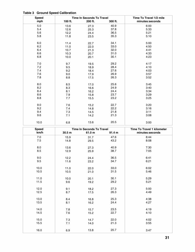
Table 3 Ground Speed Calibration
Speed mph
Time To Travel 1/2 mileminutes:seconds
Time In Seconds To Travel 100 ft. 200 ft. 300 ft.
6:005:335:215:10
5:004:504:414:334:23
4:174:104:033:573:52
3:453:403:343:293:25
3:203:163:113:08
3:00
13.612.612.211.8
11.411.010.710.310.0
9.79.59.29.08.8
8.58.38.17.97.7
7.67.47.37.1
6.8
27.325.324.423.5
22.722.021.320.720.1
19.518.918.417.917.5
17.016.616.215.815.5
15.214.814.514.2
13.6
40.937.836.535.3
34.133.032.031.030.1
29.228.427.626.926.3
25.624.924.423.723.2
22.722.221.821.3
20.5
5.05.45.65.8
6.06.26.46.66.8
7.07.27.47.67.8
8.08.28.48.68.8
9.09.29.49.6
10.0
Speed km/h
Time To Travel 1 kilometerminutes:seconds
Time In Seconds To Travel 30.5 m 61.0 m 91.4 m
8:448:08
7:307:05
6:416:21
6:025:46
5:295:21
5:004:49
4:384:27
4:194:10
4:023:55
3:47
15.914.8
13.612.9
12.211.6
11.010.5
10.09.6
9.18.7
8.48.1
7.87.6
7.37.1
6.9
31.729.5
27.325.9
24.423.2
22.021.0
20.119.2
18.217.5
16.816.2
15.715.2
14.714.0
13.8
47.643.2
40.938.7
36.534.7
33.031.5
30.129.2
27.326.3
25.324.4
23.522.7
22.021.3
20.7
7.07.5
8.08.5
9.09.5
10.010.5
11.011.5
12.012.5
13.013.5
14.014.5
15.015.5
16.0
31

4.9.7 FIELD CALIBRATION
To verify the application rates in the field, followthis procedure:
1. Fill the tank to the neck with water and markthe level of water.
2. Check that all screens are clean.
3. Set the chemical system pressure to thedesired value and run the tractor at theselected engine RPM in the selected gear.
4. Drive through the measured distance whilespraying.
5. Refill the tank to the same mark and measurethe amount required.
6. Divide the amount of liquid sprayed by thearea covered to determine the applicationrate.
=Appl. Rate = Volume sprayed Area covered
gals (liters)acre (hectare)
Table 5 Conversions
1 km .................................................. 0.62 mile1 ha ................................................... 2.5 acres1 g ..................................................... 0.035 oz.1 kg ...................................................... 2.2 lbs.1 g/ha ......................................... 0.014 oz/acre1 kg/ha .......................................... 0.88 lb/acre1 ml ............................................... 0.035 fl. oz.1L .............................................. 0.264 gal (US)1L .............................................. 0.22 gal (Imp.)1L/s .........................................15.85 gpm (US)1L/s ....................................... 13.20 gpm (lmp.)1 kPa ................................................. 0.145 psi1 mm .................................................... 0.04 in.1 m ........................................................ 3.28 ft.1 L/ha ................................ 0.106 gal (US)/acre1 L/ha .............................. 0.088 gal (Imp.)/acre
4.9.6 AREA COVERED
To determine application rates, it is necessary toknow the area covered by the sprayer during onepass. Table 4 gives the area for six widths:
Table 4 Actual Sprayer Coverage
SprayerWidth
Acres1/2 mile 1/4 mile
Hectares1/2 km 1/4 km
60'80'90'100'120'132'
3.644.855.456.067.288.00
1.822.422.733.033.644.00
1.451.942.182.452.90.3.20
0.730.971.091.221.451.60
32

4.10 FIELD OPERATION
OPERATING SAFETY1. Read and understand the Operator’s Manual
and all safety signs before using.
2. Place all controls in neutral, stop tractor engine,turn monitor off, set park brake, remove ignitionkey, wait for nozzles to stop spraying beforeservicing, adjusting, repairing or unplugging.
3. Before spraying a field, be familiar with allpotential hazards: trees, rocks, ditches, gullies,etc. Plan the spraying route to avoid hazards.Remember you are driving a wide machine.USE CAUTION WHEN CORNERING.
4. Keep hands, feet, hair and clothing away fromall moving and/or rotating parts.
5. Do not allow riders on the sprayer or tractorduring operation or transporting.
6. Clear the area of all bystanders, especiallychildren, before starting or filling with water orchemical.
7. Stay away from wing pinch points when foldingor extending wings. Keep others away.
8. Stay away from power lines when extending orfolding wings. Electrocution can occur withoutdirect contact.
9. Read chemical manufacturers warnings, instruc-tions and procedures before starting and followthem exactly.
Follow this procedure when using the sprayer:
1. Attach sprayer to the machine (see Section4.8).
2. Review and follow the pre-operation checklist(see Section 4.4).
3. Review the location and function of all con-trols (see Section 4.6).
4. Read and follow chemical manufacturers'instructions.
5. Calibrate the sprayer so you know exactlyhow much chemical is being applied (seeSection 4.9). The application of excesschemicals, even in small amounts, can havedetrimental affects. Recalibration at the startof the season or when changing chemicals isa must.
6. Transport the sprayer to the working area(See Section 4.12).
7. Convert into field position (see Section 4.11).
10. Do not breathe, touch or ingest chemicals.Always wear protective clothing and followsafe handling procedures.
11. Spray only when potential for chemical driftis at a minimum. Even small amounts canaffect neighboring crops or sensitive plantsand people.
12. Dispose of chemical containers by triplerinsing them into the sprayer tank or thor-oughly rinsing, crushing and delivering toregional disposal site.
13. In case of poisoning, get immediate medicalattention.
14. Only rinse sprayer while still in the field.Spray the rinse thinly over the field alreadysprayed. Never contaminate the farmyardor drainage systems with sprayer rinse.
15. Do not eat in the field when spraying.
16. Before applying pressure to the hydraulicsystem, make sure all components are tightand that steel lines, hoses and couplings arein good condition.
17. Before applying pressure to chemicalsystem make sure that all connections aretight and that all hoses and fittings are ingood condition.
18. Review safety instructions annually.
33

34
8. After arriving at the field, fillthe sprayer.
9. Extend the hose from thesupply vehicle or pump tothe sprayer. Water can beadded through the top lid orbottom fill fitting.
10. To top fill:
a. Place the water hose into thetop lid, start the pump on thesupply vehicle and run untilthe tank is full. Stop thepump, remove hose and closethe lid.
IMPORTANT
Be sure the water is clean.Clean water is necessary toprevent screen and checkvalve plugging.
b. Do not run pump until the tank is 1/4 fullof water. Water is required in the pump tocool the seals. A head of water is re-quired to keep the pump primed. Be surethe booms are turned off.
c. Run in the circulate mode for at least 5minutes to thoroughly mix the solutionbefore starting.
IMPORTANT
If pump is not primed, stop imme-diately and bleed the air out of thepump.
IMPORTANT
It is recommended that thewater supply system beequipped with a pump fortransferring water.
DANGER1. Wear rubber gloves, eye protection and
protective clothing whenever handlingchemicals.
2. Do not breathe vapor or ingest chemicalsand avoid contact with exposed skin.
3. Follow chemical manufacturers' instruc-tions.
Fig. 23 CHEMICAL CIRCUIT
Fig. 22 TOP FILLING
ca

f. When the tank is full, close valve at thesprayer, close valve at the supply vehicle andstop the pump on the supply vehicle. Thiswill prevent back flushing from the sprayer.
g. Disconnect the water hose and secure thecap.
h. Run the pump to allow the solution tocirculate. Mix for 2 minutes before starting tospray.
i. Move the supply vehicle out of the way.
1. Wear rubber gloves, eye protection andprotective clothing whenever handlingchemicals.
2. Do not breathe vapor or ingest chemicalsand avoid contact with exposed skin.
3. Follow chemical manufacturers' instruc-tions.
1. Do not burn chemical containers as toxicfumes could contaminate the area.
2. Do not discard chemical containers inditches.
3. Do not place containers in landfills.4. Dispose at nearest container disposal site.
when empty.
iv. Repeat with the next container until allthe chemical has been added.
v. Discard used containers at yournearest container disposal site.
e. While the tank is filling, add the chemical.
i. Start the sprayer pump for agitation.
ii. Add the chemical through the top lid,the eductor tank on the water supplyvehicle.
iii. Triple rinse each chemical container
IMPORTANTThe sprayer pump mustbe running to circulate thesolution in the systemand provide agitation.
11. To bottom fill:
a. Remove cover onbottom fill fitting, attachhose and secure withcam-locks.
b. Open valve to allow theflow of water into thetank.
c. Open the valve at thesupply vehicle, start thesupply source pump andfill the sprayer.
d. Start the sprayer pumpto circulate waterthrough the system.
Fig. 24 QUICK FILL
IMPORTANTBe sure the water is clean. Clean water isnecessary to prevent screen and checkvalve plugging.
IMPORTANTDo not start the sprayer pump until thewater from the supply vehicle has started toflow. Water is necessary to cool andlubricate the pump seals. Without water,the seals will fail in a few minutes.
35
2
2
6
2
DANGER
DANGER
36
12. Although well water is recommended,surface water can be used if it isthoroughly filtered. Be sure to keepthe filters clean when using thismethod.
13. If using wettable powders, seerecomndation below for pre-mixprocedure, remove the top tank lidand slowly add the pre-mixed powder.Be sure the tank is at least 1/2 full ofwater and the pump is running.
If the powder is not added slowly,clumps of powder will be drawn intothe suction line and plug the screenin the filter.
14. If foaming occurs, add an anti-foaming additive to the tank.
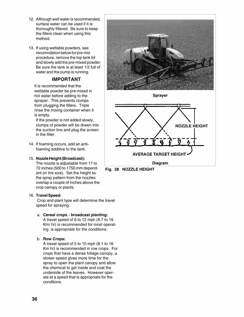
15. Nozzle Height (Broadcast):The nozzle is adjustable from 17 to72 inches (500 to 1750 mm depend-ant on tire size). Set the height sothe spray pattern from the nozzlesoverlap a couple of inches above thecrop canopy or plants.
Diagram
Fig. 28 NOZZLE HEIGHT
Sprayer
IMPORTANTIt is recommended that thewettable powder be pre-mixed inhot water before adding to thesprayer. This prevents clumpsfrom plugging the filters. Triplerinse the mixing container when itis empty.
16. Travel Speed: Crop and plant type will determine the travelspeed for spraying.
a. Cereal crops - broadcast planting:A travel speed of 6 to 12 mph (9.7 to 19.Km/ hr) is recommended for most operat-ing is appropriate for the conditions.
b. Row Crops:A travel speed of 5 to 10 mph (8.1 to 16Km hr) is recommended in row crops. Forcrops that have a dense foliage canopy, aslower speed gives more time for thespray to open the plant canopy and allowthe chemical to get inside and coat theunderside of the leaves. However oper-ate at a speed that is appropriate for theconditions.

37
Fig. 29 TRAVEL PATTERN (BROADCAST)
17. For broadcast spraying:It is recommended that the operator makeone pass around a field to start and thenspray back and forth to obtain the bestresults. Using a marker system helps toprevent skips or overlap.
If your field has headlands, be sure to allowsufficient space for turning.
18. For row crop spraying, start at one edge ofthe field and go back and forth until the fieldis completed.
19. Be sure the sprayer is calibrated, the nozzleheight and pressure are known and thetractor gear and RPM are determined beforestarting to spray (see Section 4.9).
Fig. 31 SPRAYING
Fig. 30 CONTROL BOXES (TYPICAL)
20. Proceed down the field at aconstant speed. Use the se-lected gear, engine RPM andground speed determined duringthe calibration of the machineapplication rate.
21. Place the Master Boom switch inthe OFF position and the appro-priate Boom switches in the ONposition.
22. Turn the booms ON with theBoom Master switch as thenozzles pass over the edge of thealready sprayed headland andcome to the area to be sprayed.Use the individual boom switchesas appropriate when finishing afield.
23. When completing a pass andapproaching the sprayed head-land, maintain the tractor RPMand ground speed until thenozzles have covered all theplants. This will insure aconsistent application rate atthe ends of the field.

38
24. Boom Tilt:Each side of the boom isequipped with a tilt cylinderthat allows the operator to tiltthe individual boom up at theends of the field or wheneverrequired to clear obstacles.
Fig. 33 BOOM BREAK-AWAY
Fig. 32 BOOM TILT CYLINDERS
25. Boom Break-Away:Each boom isdesigned with abreak-away hingebetween the outerbooms and theboom extention.Each of thesehinges will break-away when theboom strikes anobstruction toprevent damagingthe boom.
IMPORTANT
The machine isshipped from thefactory with a lockbolt through thehinge mechanism.Always remove lockbolt before startingto use in the field.
Field
Shipping Lock Bolt

39
26. Fence Row Nozzle:The sprayer is equipped with a fencerow circuit to provide coverage next to afence or the edge of a field. Open thevalve in the line when spraying next to afence. Turn the valve off when sprayingin the field.
Nozzle Location
Fig. 40 FENCE ROW CIRCUIT
Valve
Fig. 41 NORAC AUTO LEVELING VALVE
27. Norac Auto LevelingSystem (Optional):The sprayer can beequipped with an "autonorac" leveling system.The control valve ismounted on the centersection and connectsinto the hydraulic systemto keep the booms level.

40
DANGER POISON
WARNING POISON
CAUTION POISON
Toxicity Level Protective Gear
Goggles, Respirator,Gloves and Skin Protection.AvoidFumes.
Goggles, Gloves and SkinProtection. AvoidFumes.
Gloves and Skin Protection.AvoidFumes.
28. Pesticide Hazards:Extreme care must be taken when workingaround chemicals. Be familiar with the toxicitylevels of the chemicals you are using andrecommended protective gear that eachoperator should use before starting.
A. Toxicity Levels:Every pesticide container has a label on itthat designates its level of toxicity. Thistoxicity level then requires the operator touse specific protective gear wheneverworking with this chemical.
Low - CAUTION
High - DANGER
Medium - WARNING
Fig. 42 TOXICITY LEVELS

41
B. Personal Protection:To reduce or eliminate contact withherbicides, it is necessary to wear ad-equate protective clothing, respirators,boots, goggles and gloves. The use ofthis equipment is essential for good healthespecially when applying some of themore toxic herbicides.
a. Respirators - Protection againstinhalation (but no skin contact) isprovided quite economically by theuse of face mask respirators. Choosea mask that will fit your face andcheck with the company about thedetails of filters and chemical car-tridges used in the respirator model.Note that full and half face maskscannot be worn securely by men withbeards, whiskers, sideburns andmoustaches. Instructions on theoperational life and performance offilters and cartridges generally accom-pany the products. However, whencarrying out spray operations, it iswise to change the filters each dayand the cartridges should be replacedwhen chemical odour is noticed.Wash the face mask with warm waterand soap before installing a newcartridge and filter. Do not storecartridge and filters in the chemicalstorage area, as they can absorb thechemical even when not in use.
b. Goggles - When a full mask is notworn, the use of protective goggles isnecessary and is recommended toprotect the eyes from pesticidevapour, solids, and accidentalsplashes particularly. Safety supplycompanies offer a range of goggles.Many goggles are resistant to chemi-cals, some have specially treatedlenses to reduce fogging, others haveanti-fogging ventilation. Prescriptiontype glasses are also available towhich side shields can be attached.
c. Gloves - Non-absorbent glovesshould be worn at all times whenhandling, mixing and applying pesti-cides. Neoprene has been found tobe superior to rubber in resisting thepenetration of pesticides. Otherfactors to be considered in selectingsuitable gloves include sense oftouch, wet grip, and cut and abrasionresistance. Gloves should not havefabric wristbands or lining and shouldfit properly. Always wash the gloveinside and out after use. Leathergloves are not suitable.
d. Footwear - Non-absorbent footwearshould be worn when applying pesti-cides. It is suggested that the mostsuitable boot is one that is kneelength, acid and solvent resistant andribbed to prevent slippage. Neopreneis considered much superior torubber. Leather boots are not suit-able.
e. Clothing - For general protectioncoveralls should be worn, along withgloves and a hat to minimize thehazard of the skin absorbing pesti-cides. Clothing should be changedand washed regularly followingspraying. You can now purchasedisposable clothing that providesprotection against exposure resultingfrom pesticide drift, splashing or spills.These garments (overalls, shirts andpants, head cover, and aprons) arelight weight and cooler than rubberarticles. Protective equipment andclothing are available from safetysupply companies. Never use leathergarments e.g. jackets, gloves, orshoes during the handling or applica-tions of pesticides. Leather canabsorb the chemical and it is verydifficult to decontaminate leatherarticles.

29. Chemical Application:
a. Dilution: Pest control is dependent uponthe application of minute amounts of atoxic substance. This process starts withthe proper mixing of the toxic materialwith water. It is very important that theoperator read the mixing and dilutioninstructions on the chemical containerbefore starting. Combine the chemicaland water in the proportions recom-mended on the container only. Impropermixing can damage the crops or not affectthe pests.
b. Wettable Powders: It is recommendedthat wettable powders be pre-mixed in themixing tank before drawing into the maintank or added very slowly through the topcover. Be sure to allow at least 5 minutes
42
of circulation and agitation before startingto spray. Any clumps or sludge can clogthe suction screen or nozzles. Unlessyou stop and clean the machine,skipping and poor coverage will occur.
A. Ground Speed Sensor (Optional):Sky Trak Speed Sensor, install permanufacturer's instruction and calibrateper instruction in Raven Auto RateController manual.
B. Speed Interface Cable.Consult Fast Sprayers for correct cable.
30. Ground speed sensor
Fig. 47 SKY TRAK SPEED SENSOR
31. Foam Mark System(Optional):A sprayer can be equipped with a foammarking system. It consists of a foamconcentrate tank ,50 gallon fresh watertank, lines, a mixing chamber on theboom and an dispenser funnel on eachboom. Be sure the dispenser hangsdown when the boom is extended.Switch the system on as required todispense foam across the field.
Direct Injection (Foam Concentrate Tank Shown)
Fig. 48 FOAM MARKER SYSTEMMixing Chamber Mounted on Wings

WARNING
Do not dispose of it in the farmyard orin drainage ditches.
43
Fig. 53 CONTROL SYSTEM
32. Chemical Circuit ControlSystem:Sprayers are equipped withchemical circuit controlcomponents that aremounted on the mainsupply tank carrier, centersection, and wings. Whenequipped with the automaticcircuit controller, thevalves, flow meter andsolenoids are all mountedon the main supply tabnkcarrier, center section, andwings.
33. Mix only the quantity ofspray required for the job.Excess chemicals aredifficult to store and dis-pose of. Do not dispose ofthem in the farmyard oryour drainage system.
They will contaminate these areas.
34. Store chemicals only in their original containers under lock and key to prevent children or animals fromtouching them.
35. Be very careful to wear the proper protective gear such as rubber gloves and goggles to protectyourself. Thoroughly wash all protective gear with a good detergent after use to remove all chemi-cals.
36. Never allow chemicals or solutions to touch the skin. Some can be absorbed through the skin.Should such a contact occur, flush the affected area immediately with clear water. Wash the areathoroughly with detergent to remove any residue.
37. When spraying is done, the machine should always be rinsed. Follow this procedure:
a. Add 25 to 50 gallons of water to the tank.
b. Run the pump, wash circuit and agitator for 5 minutes to circulate and rinse the inside of thetank.
c. Spray the rinse thinly over the previously sprayed field.
38. When spraying is finished for the season or when switching chemicals, wash the sprayer using themethod described in the Maintenance Section.

44
The sprayer is designed to easily convert fromtransport to field or field to transport.
When converting from transport to field, followthis procedure:
1. Clear the area of bystanders, especiallychildren, before starting.
2. Convert only in an area that is free ofoverhead obstructions and power lines.Electrocution can occur without directcontact.
4.11 TRANSPORT/FIELD CONVERSION
Fig. 55 BOOM CYLINDER VALVE
3. Place all controls in neutral, stop engine, setpark brake and remove ignition key beforedismounting.
4. Open the valve to the boomlift cylinder that allows theboom to lower.
DANGER
ELECTROCUTION HAZARDKEEP AWAY FROM POWER LINES
1. Stay well away from power lineswhen folding or extending wings.Electrocution can occur withoutdirect contact.
2. Lower wings completely beforemoving or transporting.
To prevent serious injury or death fromelectrocution:
805

6. Be sure there issufficient space toswing the booms intotheir field position.
7. Start the tractor andrun at 1/3 throttle toprovide oil for boomposition cylinders(Refer to Section 4.6for Controller SwitchFunctions).
8. Raise booms up to liftthem out of theircradles.
9. Extend inner boomsout until they are 90° tothe frame. Watch forany interference.
10. Pivot outer booms outinto their fully extendedposition.
11. Lower boom to itslowest position.
12. Be sure foam markercup is hanging down.
13. Reverse the aboveprocedure whenconverting from field totransport configuration.
45
Clearing Cradle
Inner Boom Extending
Outer Boom Extension
Extended
Fig. 56 EXTENDING BOOMS

4.12 TRANSPORT
TRANSPORT SAFETY
1. Read and understand ALL the information inthe Operator’s Manual regarding proceduresand SAFETY when operating the Sprayer inthe field and/or on the road.
2. Check with local authorities regardingsprayer transport on public roads. Obey allapplicable laws and regulations.
Fast Distributing sprayers are designed to beeasily and conveniently moved from field to field.When transporting, follow this procedure:
1. Be sure all bystanders are clear of the ma-chine.
2. Keep to the right and yield the right-of-way toallow faster traffic to pass. Drive on the roadshoulder, if permitted by law.
3. Make sure the SMV (Slow Moving Vehicle)emblem and all the lights and reflectors thatare required by the local highway and trans-port authorities are in place, are clean andcan be seen clearly by all overtaking andoncoming traffic.
3. Always travel at a safe speed. Use cautionwhen making corners or meeting traffic.
4. Make sure the SMV (Slow Moving Vehicle)emblem and all the lights and reflectors thatare required by the local highway and trans-port authorities are in place, are clean andcan be seen clearly by all overtaking andoncoming traffic.
Table 6 Travel Speed vs Weight Ratio
46

47
4.13 STORAGESTORAGE SAFETY
1. Store unit in an area away from humanactivity.
2. Do not permit children to play on or aroundthe stored sprayer.
3. Unhook and store in the transport configu-ration.
4.13.1 PLACING IN STORAGE
At the end of the spray season, the machineshould be thoroughly inspected and prepared forstorage. Repair or replace any worn or damagedcomponents to prevent any unnecessary downtime at the beginning of the next season. Followthis procedure:
1. Thoroughly wash the machine using a hose ora pressure washer to remove all dirt, mud,debris or residue.
2. Thoroughly wash the inside of the tank andspray system with the wash cycle to removeall chemical residue using the method de-scribed in the Maintenance Section.
3. In climates that encounter freezing tempera-tures during the storage period, the followingpreparation should be done:
a. Add 10 gallons (40 liters) of a 50:50mixture of potable RV antifreeze to therinse tank.
b. Run unit for 5 minutes in the wash andspray cycles to circulate solution to allparts of the circuit.
c. While circulating the fluid, open and closeall the valves in the chemical and eductortank circuits several times to flush all thewater from the system.
d. Draw the solution out of the chemicaltank.
e. Flush the solution out the booms.
f. Open all disconnects and drainhoses, pumps, filters, solenoidsand tanks.
g. Remove nozzles from boom.Disassemble and wash nozzle,spring, diaphram and housing.Store inside.
Nozzles
Fig. 60 STORAGE
Filters (Typical)
Pump Drain

48
4.13.2 REMOVING FROM STORAGE
When removing from storage and preparing touse, follow this procedure:
1. Clear the area of bystanders, especially smallchildren, and remove foreign objects from themachine and the working area.
2. Remove the tarpaulin if it was used for stor-age.
3. Attach the tractor to the sprayer by followingthe procedure in Section 4.8.
4. Check
a. Tank for cracks.
b. Tank hold down hardware.
c. All hardware. Tighten as required.
d. Tire pressure.
e. All sprayer and hydraulic lines, fittings andconnections. Tighten as required.
5. Lubricate all grease fittings.
6. Replace any defective parts.
7. Fill the tank with 20 gallons (75 liters) of cleanwater and run for 5 minutes in the wash cycle.Open and close all valves several times.Flush water through the booms.
Install the nozzles. Run water throughbooms, and check for leaks.
8. Repeat step 6.
9. Calibrate the pump, nozzles and sprayerbefore using.
10. Go through the pre-operation checklist (Sec-tion 4.4) before using.
4. Lubricate all grease points. Make sure allgrease cavities have been filled with grease toremove any water residue from the washing.
5. Inspect all the hydraulic hoses, couplers andfittings. Tighten any loose fittings. Replaceany hose that is badly cut, nicked, abraded oris separating from the crimped end of a fitting.
6. Inspect all the spray hoses and fittings.Tighten any loose fittings. Replace any hosethat is badly cut, nicked, abraded or is sepa-rating from a fitting.
7. Touch up all paint nicks and scratches toprevent rusting.
8. Move the machine to it's storage position.
9. Select an area that is dry, level and free ofdebris.
10. Place planks under the jack for added supportif required.
11. Unhook the machine from the tractor (Refer toSection 4.8).
12. Remove the control boxes from the cab andstore inside.
13. The tank is made out of polyethylene. Do notuse to store petroleum products. They willsoften the plastic and absorb the product.
14. It is best to store the sprayer in a shaded areato minimize the long term effect of ultravioletradiation on the plastic. If shade is not avail-able, cover the tank with a tarpaulin andsecure in place.

5 SERVICE AND MAINTENANCE
MAINTENANCE SAFETY5.1 SERVICE
5.1.1 FLUIDS AND LUBRICANTS
1. GreaseUse an SAE multi-purpose high tempera-ture grease with extreme pressure (EP)performance. Also acceptable is an SAEmulti-purpose lithium base grease.
2. Storing LubricantsYour machine can operate at top efficiencyonly if clean lubricants are used. Use cleancontainers to handle all lubricants. Storethem in an area protected from dust, dirt,moisture and other contaminants.
5.1.2 GREASING
Refer to Section 5.1.1 for recommendedgrease. Use the Maintenance Checklist pro-vide to keep a record of all scheduled mainte-nance.
1. Use only a hand-held grease gun for allgreasing.
2. Wipe grease fitting with a clean cloth beforegreasing, to avoid injecting dirt and grit.
3. Replace and repair broken fittings immedi-ately.
4. If a fitting will not take grease, remove andclean thoroughly. Also clean lubricantpassageway. Replace fitting if necessary.
1. Review the Operator's Manual and all safetyitems before working with, maintaining oroperating the Sprayer.
2. Place all controls in neutral, stop the tractorengine, turn monitor off, set park brake,remove ignition key, wait for nozzles to stopspraying before servicing, adjusting, repairingor unplugging.
3. Follow good shop practices:- Keep service area clean and dry.- Be sure electrical outlets and tools are
properly grounded.- Use adequate light for the job at hand.
4. Before applying pressure to a hydraulicsystem, make sure all components are tightand that steel lines, hoses and couplings arein good condition.
5. Before applying pressure to chemical systemmake sure that all connections are tight andthat all hoses and fittings are in good condi-tion.
6. Relieve pressure from hydraulic circuit beforeservicing or disconnecting from tractor.
7. Keep hands, feet, clothing and hair away fromall moving and/or rotating parts.
8. Clear the area of bystanders, especiallychildren, when carrying out any maintenanceand repairs or making any adjustments orfilling.
9. Place stands or blocks under the framebefore working beneath the machine.
10. Wear safety goggles, neoprene gloves andprotective clothing when working on thesprayer filled with active chemical.
11. Wash machine to remove all chemical residuebefore working on unit. Wear appropriateprotective gear at all times.
12. Protect yourself from chemical contamination.
49
5.1.2.1 MOUTING HARDWARE CHECK torque EVERY 20 hours or less,depending on field conditions, of all hardwareused to mount front sprayer. See next page forsome of the different styles of brackets used.CHECK struts and ball ends at the same time forcracks, deformation of ball retainers andassociated parts.
MAINTENANCE SAFETY
IMPORTANT NOTICE

50
5.1.3 SERVICING INTERVALS
8 Hours or Daily
1. Grease boom fold hinge. (2locations each boom).
Fig. 61 BOOM FOLD PIVOT
JOHN DEERE FRONT WHEEL ASSIST
CAT M700 SERIES JOHN DEERE TRACK

51
Fig. 62 BOOM TILT PIVOT
2. Grease boom tilt pivot.(1 location each boom).
Left
Right

52
3. Grease the boom liftparallel linkage (4locations each side8 total).
Right side shown. Left hand is opposite
Fig. 63 PARALLEL LINKAGE

53
Fig. 64 OUTER BOOM
Right
Left
4. Grease outer boom hinge. (1location each boom).
5. Grease outer boom break - awayhinge (1 location each boom).
Fig. 65 BREAK - AWAY HINGE
IMPORTANT
Make sure shipping lock boltis removed from latch beforeuse.
Right
Left

54
6. Clean chemical circuit screensin the chemical circuit filters.
a. Boom control feed line (30mesh).
Agitation
Boom Strainers (Typical)
Fig. 66 SCREENS
Boom Control Feed Lineb. Agitation (30 mesh) .
c. Boom feed lines (1 perboom valve - 50 mesh).

5.1.4 SERVICE RECORD
See Lubrication and Maintenance sections for details of service. Copy this page to continue record.
ACTION CODE: CL CLEAN L LUBRICATE R REPACK
HOURS
SERVICED BY
MAINTENANCE
L Boom Tilt Pivot (1 ea.)
8 Hours or Daily
L Boom Lift Parallel Linkage (4 ea.)
L Outer Boom Hinge (1 ea.)
L Outer Boom Break-Away Hg (1 ea.)
Annually
CL Machine
L/R Wheel Bearings
CL Chemical Circuit Screens (3)
55
L Boom Fold Hinge (2 ea.)

5.2 MAINTENANCE
By following a careful service andmaintenance program for yourmachine, you will enjoy many years
of trouble-free operation.
5.2.1 FILTER CLEANING
The fluid in the sprayer is continuallybeing filtered through a screen filter inthe boom control feed line, agitationand boom feed lines. The sprayermust have clean water to preventclogging of the screens and checkvalves when in use. These screensmust be cleaned daily or more oftenas required. To clean, follow thisprocedure:
1. At the start of each day beforethe water and chemicals areadded, the screens should bechecked and cleaned.
2. If there is water or solution in thesprayer, close Valve 2 to isolatethe screens.
3. Loosen the filter bodies by hand.Do not use a wrench as thiscould damage the filter body.
4. Remove the screens and inspectthem for dirt.
5. Clean them using clean water.
6. Inspect for holes or tears. If thereis damage, replace it.
7. Install the screens and body tothe filter heads and tighten byhand. Do not use a wrench asthis might damage the body. Donot over tighten and crack thehead.
8. Open the ball valves to allow thesolution to circulate.
9. Drain all screens before storageto avoid freezing.
Schematic
Boom Line (Typical)
56
Fig. 68 SCREENS
Agitation/Rinse System

5.2.2 TANK CLEANING
A. Daily Cleaning
At the end of the working day, clean the systemusing this procedure:
1. After the chemical solution has been com-pletely sprayed out through the booms, add20 gallons (75 liters) of clear water to the tank.
2. Run at rated speed to force the solutionthrough the agitator jets and wash head(s).Run for 5 minutes.
3. Spray the rinse lightly over previously sprayedcrop.
4. Add another 30 gallons (200 liters) of cleanwater and run rinse/wash cycle for 5 minutes.
5. Flush the rinse solution out of the booms toclean the hoses and plumbing over theappropriate crop.
6. Rinse the system again with clean water.
7. Clean the screen and nozzles.
8. Drain tank and let dry.
B. Changing Chemicals and/or AnnualWash to Remove Salt and AmineFormations
1. Do the rinse procedure outlined for DailyCleaning.
2. Add 50 gallons (200 liters) of clean water tothe tank.
3. Remove nozzles and screen and washseparately.
4. Add 1/2 gallon (2 liters) of household ammo-nia to the tank (1 part ammonia to 100 partswater).
5. Run rinse/wash cycle for 5 minutes.
6. Spray half the solution out the boomsover theappropriate crop .
7. Let the balance sit for a minimum of 8 hours,overnight is best.
8. Run wash cycle for 10 minutes and spraysolution out the booms on the appropriate
C. Changing Chemicals and/or AnnualWash to Remove Esters of 2, 4-D andMCPA Formations
1. Do the wash and rinse procedures outlined forDaily Cleaning.
2. Add 50 gallons (200 liters) of clean water tothe tank.
3. Remove nozzles and screen and washseparately.
4. Add dishwasher detergent to the tank (2lbs./50 gal or 1 kg/300 l of water).
5. Run rinse/wash cycle.
6. Spray the solution out the booms on theappropriate crop and drain thoroughly.
7. Add 50 gal (200 l) of clean water to the tank.
8. Add 1/2 gal (2 l) of household ammonia to thetank (1 part ammonia to 100 parts of water).
9. Run wash cycle.
10. Spray 1/2 the solution out the booms.
11. Let the balance sit for a minimum of 8 hours,overnight is best.
12. Run rinse/wash cycle for 10 minutes andspray out the booms on the appropriate crop.
13. Rinse the system thoroughly with clean waterand flush out the booms.
14. Drain the entire system and let dry.
57
WARNING
Do not enter tank at any time.
crop.
9. Rinse the system thoroughly with clean waterand flush out the booms over the appropriatecrop .
10. Drain the entire system and let dry.
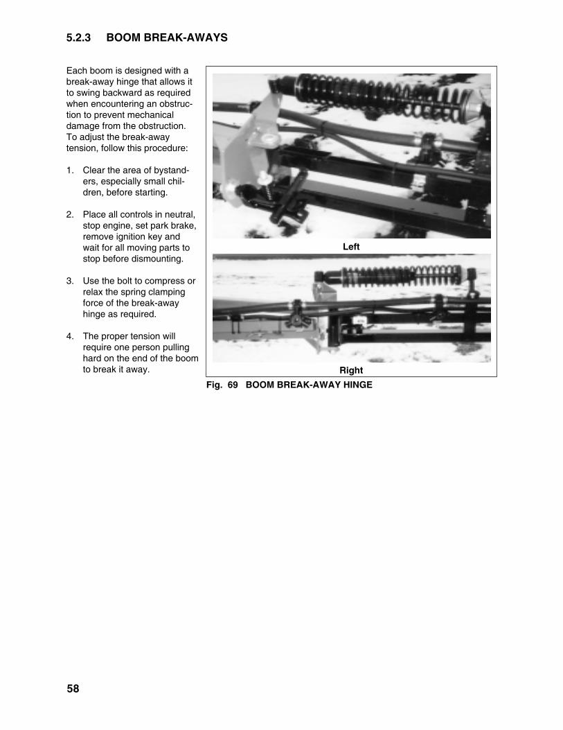
5.2.3 BOOM BREAK-AWAYS
Each boom is designed with abreak-away hinge that allows itto swing backward as requiredwhen encountering an obstruc-tion to prevent mechanicaldamage from the obstruction.To adjust the break-awaytension, follow this procedure:
1. Clear the area of bystand-ers, especially small chil-dren, before starting.
2. Place all controls in neutral,stop engine, set park brake,remove ignition key andwait for all moving parts tostop before dismounting.
3. Use the bolt to compress orrelax the spring clampingforce of the break-awayhinge as required.
4. The proper tension willrequire one person pullinghard on the end of the boomto break it away.
58
Fig. 69 BOOM BREAK-AWAY HINGE
Left
Right

59
5.2.4 BOOM STRAIGHTNESS
The boom on each machine aredesigned with set screw adjust-ments that provide a method toadjust for straightness. Bykeeping the booms straight, thesprayer produces a consistentclearance to the crop.
When adjusting boom straight-ness, follow this procedure:
1. Clear the area of bystanders,especially small children,before starting.
2. Place machine in field con-figuration with the boomabout waist high.
3. Place all controls in neutral,stop engine, set park brake,remove ignition key and waitfor all moving parts to stopbefore dismounting.
4. Sight along the boom to besure it is straight at eachhinge.
5. Loosen the position bolt jamnut at a hinge.
6. Turn position bolt to therequired position and tightenjam nut to its specifiedtorque.
7. Repeat with other hinges asrequired.
Fig. 71 BOOM STRAIGHTNESS
Break-away
Sighting
Inner Boom
Outer Boom

6 TROUBLE SHOOTING
The Fast Distributing Field Sprayer uses a pressure circuit to deliver a chemical compound in solution to aseries of nozzles for application to crops. It is a simple and reliable system that requires minimal mainte-nance.
In the following section, we have listed many of the problems, causes and solutions to the problems thatyou may encounter.
If you encounter a problem that is difficult to solve, even after having read through this trouble shootingsection, please call your local Fast Distributing dealer or distributor. Before you call, please have thisOperator's Manual and the serial number from your machine ready.
PROBLEM CAUSE SOLUTION
Sprayer is not stable. Moves Low tire pressure. Add air to tires.from side-to-side.
Loose wheel bolts. Tighten wheel bolts.
System loses pressure. Filter screen plugged. Clean chemical line screens.
Pump worn. Check and repair or replacepump.
Faulty suction hose. Check for collapsed suctionhose. Replace hose.
Faulty regulator. Replace regulator.
Hose leaking. Tighten hose or replacehose.
Sprayer pressure too high. Return hose plugged. Clean or replace hose.
Faulty pressure sensor. Calibrate sensor. Replaceas required.
Faulty regulator. Repair or replace valve.
Wrong agitation valve setting. Open agitation valveslightly until pressure goesto required range.
60
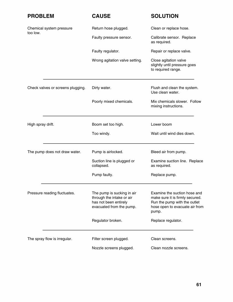
61
PROBLEM CAUSE SOLUTION
Chemical system pressure Return hose plugged. Clean or replace hose.too low.
Faulty pressure sensor. Calibrate sensor. Replaceas required.
Faulty regulator. Repair or replace valve.
Wrong agitation valve setting. Close agitation valveslightly until pressure goesto required range.
Check valves or screens plugging. Dirty water. Flush and clean the system.Use clean water.
Poorly mixed chemicals. Mix chemicals slower. Followmixing instructions.
High spray drift. Boom set too high. Lower boom
Too windy. Wait until wind dies down.
The pump does not draw water. Pump is airlocked. Bleed air from pump.
Suction line is plugged or Examine suction line. Replacecollapsed. as required.
Pump faulty. Replace pump.
Pressure reading fluctuates. The pump is sucking in air Examine the suction hose andthrough the intake or air make sure it is firmly secured.has not been entirely Run the pump with the outletevacuated from the pump. hose open to evacuate air from
pump.
Regulator broken. Replace regulator.
The spray flow is irregular. Filter screen plugged. Clean screens.
Nozzle screens plugged. Clean nozzle screens.

PROBLEM CAUSE SOLUTION
Can't develop enough pressure. Broken pressure regulator. Replace pressure regulator.
Worn pump. Repair or replace pump.
Leaking hose or fitting. Replace hose or tighten fitting.
Pump running too slow. Increase oil flow to pump toincrease pump speed.
Wrong agitation valve setting. Close agitation valve slightlyuntil pressure goes to requiredrange.
No pressure reading. Poor connection. Clean connection. Push firmlytogether.
Defective sensor. Replace sensor.
Defective controller gauge. Replace gauge.
Spray won't shut off. Defective switch in monitor. Replace switch.
Solenoid valve doesn't close. Magnet stuck. Spring broken.Replace defective parts.
Controller doesn't control sprayer. Blown fuse. Replace fuse.
Poor connection. Pull connections apart. Cleanterminals. Reconnect.
No power. Connect power wire.
Refer to Controller Manual. Refer to Controller Manual.
Booms bouncing. Traveling too fast. Slow down.
62

7 SPECIFICATIONS
7.1 MECHANICAL FM9400 SERIES
SPECIFICATIONS SUBJECT TO CHANGE WITHOUT NOTICE
63
DIMENSIONS/INCHES
Length:
Width: Field:Transport:
Weight: Empty:1000 Gallon 3 pt CarierFront Mount boom:
Tank Capacity(Gallons):
Working Spray Range:
PUMP
Hydraulically driven:(Input)
Performance:(Output)
Call for other pump options
Tank Agitators:
Wash Head:
OPTIONAL:CONTROLLERS450 Raven
Power: 12vCab Fold Box:
60 FOOT
233
720190
15002498
750,1000,1250
20-68*
150-206
7-11 GPM
214 GPM
JET AGITATION
2
12 VOLT 15 AMP12 VOLT 10 AMP
80 FOOT
276
960190
15002627
750,1000,1250
20-68*
9306C-HM1
11 GPM
214 GPM
JET AGITATION
2
12 VOLT 15 AMP12 VOLT 10 AMP
90 FOOT
276
1080190
15002724
750,1000,1250
20-68*
9306C-HMI
11 GPM
214 GPM
JET AGITATION
2
12 VOLT 15 AMP12 VOLT 10 AMP
100 FOOT
276
1200190
15002820
750,1000,1250
20-68*
9306C-HMI
11 GPM
214 GPM
JET AGITATION
2
12 VOLT 15 AMP12 VOLT 10 AMP
*Based on a John Deere 8110 FWA w/420/80R46 rears 350/80R34 fronts

7.2 BOLT TORQUE
BoltDiameter"A"
1/4"5/16"3/8"7/16"1/2"9/16"5/8"3/4"7/8"1"
(6)(10)(20)(30)(45)(70)(95)
(165)(170)(225)
SAE 2N.m (lb-ft)
SAE 5N.m (lb-ft)
SAE 8N.m (lb-ft)
81327416195128225230345
12254572110155215390570850
(9)(19)(33)(53)(80)(115)(160)(290)(420)(630)
1736631001552203055408801320
(12)(27)(45)(75)(115)(165)(220)(400)(650)(970)
Bolt Torque *
Nut SizeAcrossFlats
(in.)
Torque Value*
(N.m) (lb-ft)
RecommendedTurns to Tighten(After FingerTightening)
(Flats) (Turns)
3/161/45/163/81/25/83/47/8
7/169/165/8
11/167/81
1-1/41-3/8
81216244662
102122
69
121834467590
111111
3/43/4
1/61/61/61/61/61/61/81/8
TubeSizeOD
(in.)
TIGHTENING FLARE TYPE TUBE FITTINGS *
1. Check flare and flare seat for defects thatmight cause leakage.
2. Align tube with fitting before tightening.
3. Lubricate connection and hand tightenswivel nut until snug.
4. To prevent twisting the tube(s), use twowrenches. Place one wrench on theconnector body and with the secondtighten the swivel nut to the torque shown.
* The torque values shown are based on lubricated connections as in reassembly.
7.3 HYDRAULIC FITTING TORQUE
CHECKING BOLT TORQUE
The tables shown below give correct torque values for various bolts and capscrews. Tighten all bolts tothe torques specified in chart unless otherwise noted. Check tightness of bolts periodically, using bolttorque chart as a guide. Replace hardware with the same strength bolt. Torque values are identified by thierhead markings.
64
ASAE BOLT MARKINGS
METRIC BOLT TORQUEBolt Size Grade 8.8 Grade 10.9 Grade 12.96mm 7 10 128mm 17 24 2910mm 33 47 5712mm 59 83 10014mm 101 131 15816mm 146 202 24718mm 201 283 34020mm 285 401 482

7.4 CHEMICAL CIRCUIT SCHEMATIC
65

7.5 ELECTRICAL SCHEMATIC
CABLE 10' CONSOLE 3 OR 6 BOOM SCS 440/450 CONSOLES
66

CABLE 33' FLOW CONTROLLER 3 OR 6 BOOM VALVES
67

68
7.6 5 FUNCTION HYDRAULIC BLOCK PARTS
Not
e: fo
r ope
nce
nter
syst
ems
only
inst
all p
lug
#10
for c
lose
d ce
nter

69
7.7 5 FUNCTION HYDRAULIC CAB BOX

70
7.8 5 FUNCTION HYDRAULIC CAB BOX SWITCH WIRING

71
7.9 OPTIONAL 7 FUNCTION HYDRAULIC BLOCK

72
7.10 7 OPTIONAL FUNCTION HYDRAULIC CAB BOX

73
7.11 OPTIONAL 7 FUNCTION HYDRAULIC BLOCK

74
8 INDEX
PAGEI
Introduction ..................................................... 1
O
Operation ..................................................... 13 Attaching/Unhooking Tractor .................... 24 Break-In ................................................... 15 Controls ................................................... 18 Equipment Matching ................................ 16 Field Operation ........................................ 33 Installing Controllers ................................ 23 Machine Components .............................. 14 Pre-Operation Checklist ........................... 15 Sprayer Calibration .................................. 27 Area Covered ..................................... 32 Controller Calibration .......................... 28 Engine RPM ....................................... 27 Field Calibration.................................. 32 Ground Speed Calibration ................... 30 Machine Yard Calibration .................... 30 Nozzle Calibration .............................. 28 Storage .................................................... 47 Placing In Storage .............................. 47 Removing From Storage ..................... 48 To The New Owner or Operator ................ 13 Transport ................................................. 46 Transport/Field Conversion ...................... 44
PAGE
S Safety ........................................................ 2 Chemical Safety ........................................ 5 General Safety .......................................... 3 Hydraulic Safety ........................................ 6 Maintenance Safety ................................... 6 Operating Safety ....................................... 4 Safety Signs .............................................. 7 Sign-Off Form ............................................ 8 Storage Safety ........................................... 7 Tire Safety ................................................. 7 Transport Safety ........................................ 7Safety Sign Locations ..................................... 9Service and Maintenance .............................. 49 Maintenance ............................................ 56 Boom Break-Aways ............................ 58 Boom Straightness ............................. 59 Filter Cleaning .................................... 56 Tank Cleaning .................................... 57 Mounting brackets .............................. 49 Service .................................................... 49 Fluids and Lubricants ......................... 49 Greasing ............................................ 49 Service Record ................................... 55 Servicing Intervals ............................. 50Specifications ............................................... 64 5 Function Hydraulic Block Parts ............. 68 5 Function Hydraulic Cab Box ................. 69 5 Function Hydraulic Cab Box Switch Wiring ....................................... 70 7 Optional Function Hydraulic Cab Box.... 71 7 Function Hydraulic Cab Box Switch Wiring ....................................... 72 Bolt Torque .............................................. 64 Chemical Circuit Schematic ..................... 65 Electrical Schematic ................................ 66 Hydraulic Fitting Torque ........................... 64 Mechanical .............................................. 64 Optional 7 Function Hydraulic Block ........ 71
T
Trouble Shooting ........................................... 63


FAST DISTRIBUTING INC.54859 COUNTY ROAD 44
MOUNTAIN LAKE, MN 56159PHONE (800) 772-9279PHONE (507) 427-3861
FAX (507) 427-3030WEBSITE: www.fastsprayers.com
PRINTED INISSUE DATE: APRIL 2008 PART NUMBER: 961