fnp-led graphic led display io v1 0
DESCRIPTION
graphicTRANSCRIPT

FireNET PlusFNP-LED Graphix LED Display
Installation and Operation Manual
Hochiki America Corporation 7051 Village Drive, Suite 100 Buena Park, CA 90621-2268 714.522.2246 Corporate Headquarters 800.845.6692 Technical Support http://www.hochiki.com
Version 1.0Created: 04/10/09
Updated: 10/30/09
PN# 1700-11000
FireNET FNP-LED I & O Manual v1.0 UL 2
Table of Contents
Table of Contents ........................................................................................................................... 2�
Section 1 – Introduction
......................................................................................................................................................... 3�1.1 Limitations of Fire Alarm Systems ........................................................................ 3�
Section 2 – General Wiring Specifications
......................................................................................................................................................... 6�
Section 3 – Installing the FNP-LED Graphic LED Display
......................................................................................................................................................... 7�3.1 Overview of the FNP-LED .................................................................................... 7�3.1.1 Enclosure Sizes and Options ........................................................................... 7�
3.2 Controls and Indications ....................................................................................... 8�3.3 Specifications........................................................................................................ 9�3.4 Mounting ............................................................................................................... 9�3.5 Connections ........................................................................................................ 10�3.5.1 Terminating Jumper ....................................................................................... 11�
3.6 Addressing .......................................................................................................... 12�3.7 Programming ...................................................................................................... 13�3.8 Adding or Changing LED Positions ..................................................................... 13�3.9 Maintenance ....................................................................................................... 14�
Appendix A ................................................................................................................................... 15�Ordering the FNP-LED Graphic LED Display ........................................................... 15�
WARRANTY .................................................................................................................................. 25�
FireNET FNP-LED I & O Manual v1.0 UL 3
Section 1 – Introduction
The FireNET FNP-LED Graphic LED Display provides a flexible and expandable solution for graphical LED display panels via a simple four-wire data link connected to the FireNET Plus control panel (FW version must be V07.0000 or higher).
1.1 Limitations of Fire Alarm Systems
Follow Recommended Installation Guidelines: To achieve early fire detection, fire detection sensors should be installed in all rooms and areas of a house, apartment, or building in accordance with the recommendations of the National Fire Protection Association Standard 72 (NFPA 72), manufacturer’s recommendations, state and local codes, and the recommendations contained in Guide for the Proper Use of System Smoke Detectors, which is made available at no charge to all installing dealers. Generally, the standards and recommendations include the following (but installers should refer to the specific guidelines above before installing):
� Sleeping Rooms: Smoke detectors should be installed in every sleeping room.
� Hallways: More than one smoke detector should be installed in a hallway if it is more than 30 feet long.
� At least Two Smoke Detectors: There should never be less than two smoke detectors per apartment or residence.
� Smoke Detectors in Alarm, Electrical, or Phone Locations: Smoke detectors should be located in any room where an alarm control is located or an alarm control connects to an electrical source or phone line. If detectors are not so located, a fire within the room could prevent the alarm control from reporting a fire.
� Notification Systems: All fire alarm systems require notification devices, including sirens, bells, horns, and/or strobes. In residential applications, each automatic alarm initiating device when activated should cause the operation of alarm notification device that should be clearly audible in all bedrooms over ambient or background noise levels (at least 15dB above noise) with all intervening doors closed.
� Alarm in Every Bedroom and Level of Residence: A smoke detector with an integral sounder (smoke alarm) should be located in every bedroom and an additional notification device should be located on each level of a residence.
� Maintenance: A maintenance agreement should be arranged through the local manufacturer’s representative and maintenance should be performed annually by authorized personnel only. To keep a fire alarm system in excellent working order, ongoing maintenance is required per the manufacturer’s recommendations and UL and NFPA standards. At a minimum the requirements of Chapter 7 of NFPA 72 (2007) shall be followed.
� Test Weekly: The alarm system should be tested weekly to make sure all sensors and transmitters are working properly. The most common cause of an alarm system not functioning when a fire occurs is inadequate maintenance.

FireNET FNP-LED I & O Manual v1.0 UL 4
Alarms Cannot Guarantee Warning or Protection: Fire alarm system cannot guarantee warning or protection against fire in every potential situation. A study by the Federal Emergency Management Agency (an agency of the United States government) indicated that smoke detectors may not go off or give early warning in as many as 35% of all fires.
Limitation on Fire Alarm Effectiveness: A fire alarm system may not provide timely or adequate warning, or simply may not function, for a variety of reasons. For example:
� No Detection: Particles of combustion or smoke from a developing fire may not reach the sensing chambers of smoke detectors because:
1. Barriers (such as closed or partially closed doors, walls, or chimneys) may inhibit particle or smoke flow.
2. Smoke particles may become cold, stratify, or not reach the ceiling or upper walls where detectors are located.
3. Smoke particles may be blown away from detectors by air outlets.4. Smoke particles may be drawn into air returns before reaching the
detector.� No Multi-Floor Detection: In general, smoke detectors on one level of a
structure cannot be expected to sense fires developing on another level.� Insufficient Smoke: The amount of smoke present may be insufficient to
alarm smoke detectors. Smoke detectors are designed to alarm, at various levels of smoke density. If such density levels are not created by a developing fire at the location of the detector, the detector will not go into alarm.
� Smoldering vs. Flaming Fires: Smoke detectors, even when working properly, have sensing limitations. Detectors that have photoelectric sensing chambers tend to detect smoldering fires better than flaming fires, which have little visible smoke. Detectors that have ionizing-type sensing chambers tend to detect fast flaming fires better than smoldering fires. Because fires develop in different ways and are often unpredictable in their growth, neither type of detector is necessarily best and a given type of detector may not provide adequate warning of a fire.
� False Alarms and Pre-Fire Disconnection: Smoke detectors are subject to false alarms and nuisance alarms and may have been disconnected by users. For example, a smoke detector located in or near a kitchen may go into nuisance alarm during normal operation of kitchen appliances. In addition, dusty or steamy environments may cause a smoke detector to falsely alarm. If the location of a smoke detector causes an abundance of false alarms or nuisance alarms do not disconnect the smoke detector, call a professional to analyze the situation and recommend a solution.
� Fast Fires and Explosions: Smoke detectors cannot be expected to provide adequate warning of fires caused by arson and children playing with matches (especially within bedrooms), smoking in bed, violent explosions (caused by escaping gas, improper storage of flammable materials, etc.).
� Heat Detectors: Heat detectors do not sense particles of combustion and are designed to alarm only when heat on their sensors increases at a predetermined rate or reaches a predetermined level. Heat detectors are designed to protect property, not life.

FireNET FNP-LED I & O Manual v1.0 UL 5
� Unheeded Warning: Warning devices (including horns, sirens, and bells) may not alert people or wake up sleepers who are located on the other side of closed or partially open doors. A warning device that activates on a different floor or level of a dwelling or structure is less likely to awaken or alert people. Even persons who are aware may not notice the warning if the alarm is muffled by noise from a stereo, radio, air conditioner or other appliance, or by passing traffic. Audible warning devices may not alert the hearing impaired (strobes or other devices should be provided to warn these people). Any warning device may fail to alert people with a disability, deep sleepers, people who have recently used alcohol or drugs, or people on medication or sleeping pills.
� Strobes: Strobes can under certain circumstances, cause seizures in people with conditions such as epilepsy.
� Drills: Studies have shown that certain people, even when they hear a fire alarm signal, do not respond or comprehend the meaning of the signal. It is the property owner’s responsibility to conduct fire drills and other training exercises to make people aware of fire alarm signals and instruct on the proper reaction to alarm signals.
� Hearing Loss: In rare instances, the sounding of a warning device can cause temporary or permanent hearing loss.
� Telephone Transmissions Problems: Telephone lines needed to transmit alarm signals from a premise to a central station may be out of service or temporarily out of service. For added protection against telephone line failure, backup radio transmission systems are recommended.
� System Failure With Age or Lack of Maintenance: System components, though designed to last many years, can fail at any time. As a precautionary measure, it is recommended that smoke detectors be checked, maintained, and replaced per manufacturer’s recommendations.
� Electrical Power Problems: System components will not work without electrical power. If system batteries are not serviced or replaced regularly, they may not provide battery backup when AC power fails.
� High Air Velocity or Dusty or Dirty Environments: Environments with high air velocity or that are dusty or dirty require more frequent maintenance.
Importance of Maintenance: In general, fire alarm systems and devices will not work without power and will not function property unless they are maintained and tested regularly.
Alarm is Not Substitute for Insurance: While installing a fire alarm system may make the owner eligible for a lower insurance rate, an alarm system is not a substitute for insurance. Property owners should continue to act prudently in protecting the premises and the people in their premises and should properly insure life and property and buy sufficient amounts of liability insurance to meet their needs.

FireNET FNP-LED I & O Manual v1.0 UL 6
Section 2 – General Wiring Specifications
Care should be taken when wiring the system to avoid situations that would contribute to inducing electrical noise from one wire to another. Induced noise can interfere with telephone communications or cause erratic system operation. Follow these general guidelines to plan your system wiring prior to installation.
� Route high and low voltage wiring separately. Maintain a minimum 2” separation between high and low voltage wiring throughout the building.
� Route control panel wiring around the perimeter of the control panel enclosure. A minimum .25” separation is required between high and low voltage wiring.
� Identify which group each wire or cable is associated with from the list below. Isolate each group’s wiring as much as possible. Avoid running a single multi-conductor cable for multiple groups of conductors.
� AC Power - Main Power Supply � Notification Appliances � SLC Circuits � Relay Outputs � Voltage Outputs � Remote Control and Auxiliary Inputs � Network Wiring (Shielded wire required) � RS485 Bus Wiring (Shielded wire required)
� Keep wiring from different groups separated as much as possible. If you must share the same conduit with different conductor groups consider using shielded cable.
� If shielded cable is used terminate the shield to the earth ground terminal block in the main control panel and leave open at field side of cable. Do not ground at both ends of cable.

FireNET FNP-LED I & O Manual v1.0 UL 7
Section 3 – Installing the FNP-LED Graphic LED Display
3.1 Overview of the FNP-LED The FireNET FNP-LED Graphic LED Display is a graphical annunciator that provides a flexible solution for fire alarm systems. The FNP-LED allows LED positions to be added or removed without wiring changes. The modular nature of the FNP-LED supports up to 88 standard LED indicators. Please contact Hochiki America for applications requiring more than 88 LED indicators.
3.1.1 Enclosure Sizes and Options The FNP-LED enclosure size can be custom ordered to accept applications requiring 24, 56 or 88 LEDs.
Enclosure Dimensions Max # of LEDs Max # of boards AM-2 14.50”W x 12.25”H x 3.50”D 24 (1) Red LED driver board
(1) LED expansion board
AM-3 14.50”W x 18.90”H x 4.25”D 56 (1) Red LED driver board (3) LED expansion boards
AM-4 14.50”W x 24.25”H x 4.25”D 88 (1) Red LED driver board (5) LED expansion boards
All FNP-LED displays contain a Red LED driver board containing 8 LEDs. LED expansion boards contain 16 LEDs in colors of red, green or yellow. Please see Appendix A for information on ordering the FNP-LED.
AM-2
AM-3
AM-4

FireNET FNP-LED I & O Manual v1.0 UL 8
3.2 Controls and Indications The FNP-LED Graphic LED Display is available with or without controls and common indicators. Models with common indicators include the following standard LED indicators:
� Fire – lights whenever a fire condition is present on the FACP � Power On – indicates if normal AC power is present at the FACP � Trouble- lights when a trouble condition is present on the FACP � Disablement – lights when a disablement is present on the FACP
Models with controls have the following switches: � Enable Controls – keyswitch which enables the Reset and Alarm Silence controls � Lamp Test – illuminates all LEDs when pressed for testing purposes � Buzzer Silence – silences the FNP-LED internal buzzer � Reset – resets the FACP � Alarm Silence – silences the notification appliance circuits on the FACP
FirePower On
Trouble
Disablement
Lamp Test
BuzzerSilence
Reset AlarmSilence
EnableControls
FireNET FNP-LED I & O Manual v1.0 UL 9
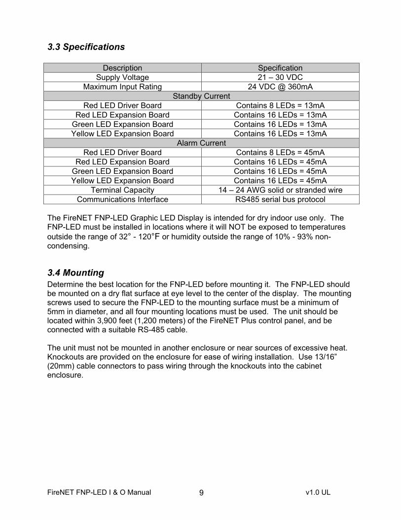
3.3 Specifications
Description SpecificationSupply Voltage 21 – 30 VDC
Maximum Input Rating 24 VDC @ 360mA Standby Current
Red LED Driver Board Contains 8 LEDs = 13mA Red LED Expansion Board Contains 16 LEDs = 13mA
Green LED Expansion Board Contains 16 LEDs = 13mA Yellow LED Expansion Board Contains 16 LEDs = 13mA
Alarm Current Red LED Driver Board Contains 8 LEDs = 45mA
Red LED Expansion Board Contains 16 LEDs = 45mA Green LED Expansion Board Contains 16 LEDs = 45mA Yellow LED Expansion Board Contains 16 LEDs = 45mA
Terminal Capacity 14 – 24 AWG solid or stranded wire Communications Interface RS485 serial bus protocol
The FireNET FNP-LED Graphic LED Display is intended for dry indoor use only. The FNP-LED must be installed in locations where it will NOT be exposed to temperatures outside the range of 32° - 120°F or humidity outside the range of 10% - 93% non-condensing.
3.4 Mounting Determine the best location for the FNP-LED before mounting it. The FNP-LED should be mounted on a dry flat surface at eye level to the center of the display. The mounting screws used to secure the FNP-LED to the mounting surface must be a minimum of 5mm in diameter, and all four mounting locations must be used. The unit should be located within 3,900 feet (1,200 meters) of the FireNET Plus control panel, and be connected with a suitable RS-485 cable.
The unit must not be mounted in another enclosure or near sources of excessive heat. Knockouts are provided on the enclosure for ease of wiring installation. Use 13/16” (20mm) cable connectors to pass wiring through the knockouts into the cabinet enclosure.

FireNET FNP-LED I & O Manual v1.0 UL 10
Four 1/5" (5 mm) mounting screws
3.5 Connections The FNP-LED requires 24VDC power and RS-485 data to operate. Connect the RS-485 data circuit to the COMMS terminals on the FireNET Plus control panel. 24VDC power may be obtained from the AUX power on the FireNET Plus panel, or from a UL listed 24VDC auxiliary power supply. Be sure to observe proper polarity on the 24VDC power and RS-485 circuit connections.

FireNET FNP-LED I & O Manual v1.0 UL 11
CO
MM
-0
VC
OM
M +
24V
3.5.1 Terminating Jumper If the FNP-LED is the last device on the RS-485 bus a terminating jumper must be installed. Only one board (the last board physically connected to the RS-485 bus) should have the jumper installed. If serial annunciators or I/O boards are installed on the circuit, the terminating jumper should be installed on only the last device located on the circuit. The jumpers must be removed on all other devices.
If there are multiple driver boards in the FNP-LED, the terminating jumper must be installed on the last board physically connected to the RS-485 bus. This is illustrated below:

FireNET FNP-LED I & O Manual v1.0 UL 12
3.6 Addressing Each of the LED driver boards in the FNP-LED Graphic LED Display must be assigned a unique address between 1 and 32. These addresses must not be shared by any other device on the RS-485 COMMS bus of the FACP. The address is set by a binary coded DIP switch on each board.
The figure below illustrates an example of addressing the LED driver modules on the FNP-LED. This example uses addresses 1 to 4.
8 LED Board1 to 8
Address 1
16 LED Board9 to 24
Address 2
16 LED Board25 to 40
Address 3
16 LED Board41 to 56
Address 4
The address for each LED driver board is set using a 6-position DIP-switch in binary fashion. Switches 1-6 represent the values 1, 2, 4, 8, 16 and 32 respectively. To set the address, move only the switches whose values when added equal the address value you wish to set, to the “ON” position. For example moving switches 1 and 3 (whose values are 1 and 4 respectively) to the “ON” position sets the address of 5 into the RS485 bus device. See the other examples below:
Addresses must be set with no power applied to the system.
ADDRESS 6 ADDRESS 13 ADDRESS 21
Shows switch actuator in the ON position.Switch Number – 1 2 3 4 5 6
Value – 1 2 4 8 16 32
1 11

FireNET FNP-LED I & O Manual v1.0 UL 13
3.7 Programming The Graphic LED Display consists of an 8-way LED board; this board also contains the common LEDs and controls if they are used. Additional 16-way LED boards may be added, up to a maximum of 32 boards
The LED boards are set by default to operate on a fire alarm condition. The outputs of the 8-way LED board are assigned to zones 1 – 8 respectively. If a 16-way LED board is added its outputs are assigned to zones 9 – 24 respectively. If additional LED boards are added their outputs will also be set to zones 9 – 24, and may need to be reprogrammed to suit the installation.
3.8 Adding or Changing LED Positions The construction of the FNP-LED Graphic Display is such that it is simple to add, remove or change the position of LED indicators without the need for special tools or wiring. The indicators are installed on a steel plate which has holes on a ¼” (6mm) grid. This steel plate is covered by a printed building plan which reveals only the areas of the plate where the indicators are located. If changes or additions are made to the building plan, a new building plan layout can be produced and installed on an existing FNP-LED panel.

FireNET FNP-LED I & O Manual v1.0 UL 14
To add or change an LED indicator:
3.9 Maintenance The FNP-LED requires little or no maintenance other than to ensure that the fascia is clean and clear of obstructions. If required, the fascia can be wiped with a barely damp cloth. Cleaning solutions other than those specifically designed for plastics such as anti static spray cleaners should not be used.
The FNP-LED should be periodically tested at the same time as the rest of the fire alarm system in a systematic manner which ensures that all indicators show the correct information. FNP-LED models with controls have a lamp test button which can be used to verify that all indicators and the internal buzzer are working correctly. The silence buzzer, silence alarm and reset control buttons should also be tested periodically.

FireNET FNP-LED I & O Manual v1.0 UL 15
Appendix A
Ordering the FNP-LED Graphic LED Display
The following enclosure styles are available for various configurations: Enclosure Dimensions Max # of LEDs Max # of boards
AM-2 14.50”W x 12.25”H x 3.50”D 24 (1) Red LED driver board (1) LED expansion board
AM-3 14.50”W x 18.90”H x 4.25”D 56 (1) Red LED driver board (3) LED expansion boards
AM-4 14.50”W x 24.25”H x 4.25”D 88 (1) Red LED driver board (5) LED expansion boards
The following circuit boards are available for various configurations: Model Circuit Board Description
FNP-LED-000 Red LED Driver Board, 8 LEDs FNP-LED-100 Red LED Expansion Board, 16 LEDs FNP-LED-010 Green LED Expansion Board, ,16 LEDs FNP-LED-001 Yellow LED Expansion Board, 16 LEDs
Installation and Maintenance Parts: Material Description
FNP-LED-FOC Fiber Optic Cable, 3.28 Feet Length (1 meter) FNP-LED-CUT Fiber Optic Cutting Tool FNP-LED-LNS Fiber Optic Lens, Replacement
FireNET FNP-LED I & O Manual v1.0 UL 16
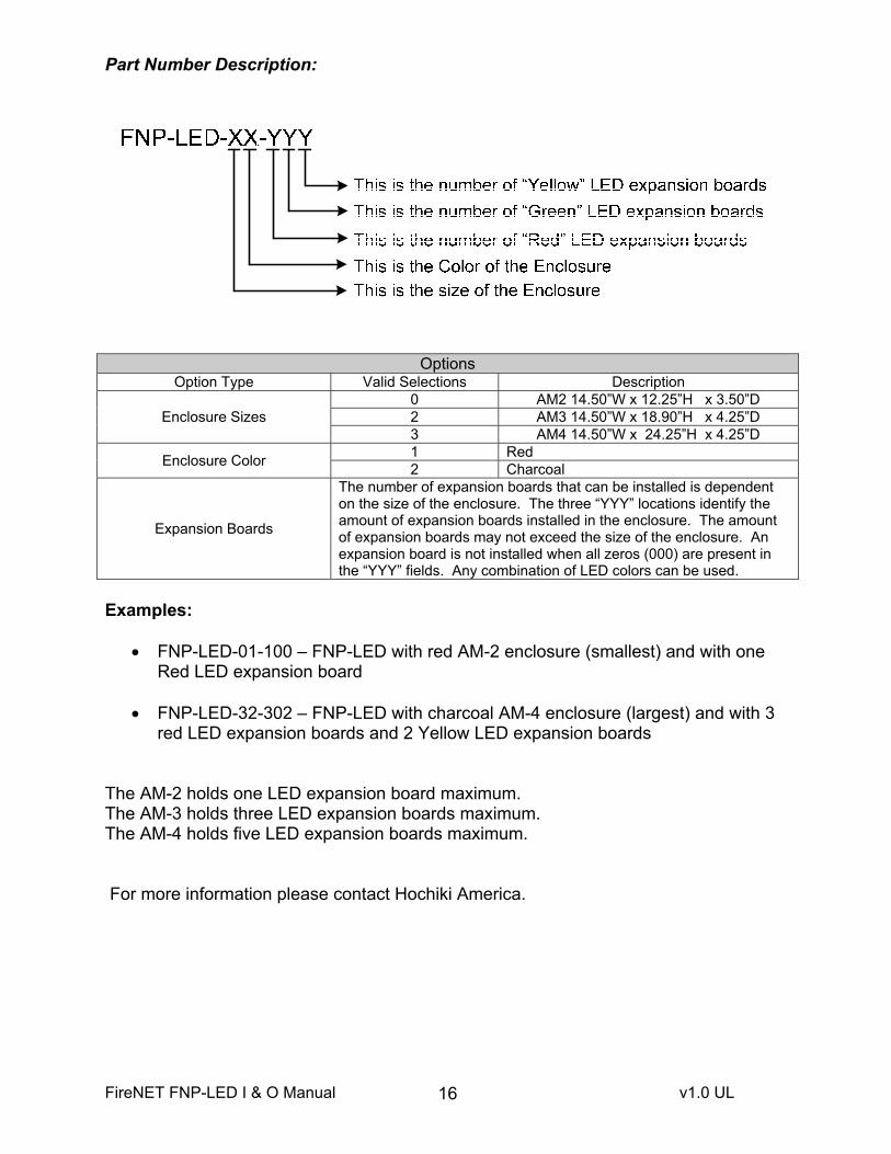
Part Number Description:
OptionsOption Type Valid Selections Description
Enclosure Sizes 0 AM2 14.50”W x 12.25”H x 3.50”D 2 AM3 14.50”W x 18.90”H x 4.25”D 3 AM4 14.50”W x 24.25”H x 4.25”D
Enclosure Color 1 Red 2 Charcoal
Expansion Boards
The number of expansion boards that can be installed is dependent on the size of the enclosure. The three “YYY” locations identify the amount of expansion boards installed in the enclosure. The amount of expansion boards may not exceed the size of the enclosure. An expansion board is not installed when all zeros (000) are present in the “YYY” fields. Any combination of LED colors can be used.
Examples:
� FNP-LED-01-100 – FNP-LED with red AM-2 enclosure (smallest) and with one Red LED expansion board
� FNP-LED-32-302 – FNP-LED with charcoal AM-4 enclosure (largest) and with 3 red LED expansion boards and 2 Yellow LED expansion boards
The AM-2 holds one LED expansion board maximum. The AM-3 holds three LED expansion boards maximum. The AM-4 holds five LED expansion boards maximum.
For more information please contact Hochiki America.

FireNET FNP-LED I & O Manual v1.0 UL 17
FNP�LED�Installation�Manual������������������������������������������������������������������������������������������������������������������
Equipment List This appendix provides models and supporting equipment for all versions of the FNP-LED.
Model Numbering The FNP-LED is a graphical annunciator containing model numbering, FNP-LED-XX-YYY for custom applications.
Reference Section, “Part Number Assignment Matrix” to select a configuration suitable for each application and then reference Section, “Hochiki Graphic Annunciator Models” to determine the model suitable for the cabinet size.
All FNP-LED include one Red LED driver board, FNP-LED-00-000. The Red LED driver board contains 8 LEDs. LED expansion boards contain 16 LEDs of red, green or yellow.
Circuit Boards The following circuit boards are provided with the FNP-LED for various LED configurations:
Cabinet Styles The following circuit boards are provided with the FNP-LED for various LED configurations:
CABINET STYLES DIMENSIONS MAXIMUM BOARD CAPACITY
FNP-LED-AM2 14.50” x 12.25” x 3.50” 1 expansion board
FNP-LED-AM3 14.50” x 18..90” x 4.25” 3 expansion boards
FNP-LED-AM4 14.50” x 24.25” x 4.25” 5 expansion boards
Installation and Maintenance Parts The following parts are recommended for installation and maintenance of the FNP-LED:
MATERIAL DESCRIPTION
FNP-LED-GDP-FOC Fiber optic cable, 3.28 feet length (1 meter)
FNP-LED-GDP -CUT Fiber optic cable cutting tool
FNP-LED-GDP -LNS Fiber optic LED lens, replacement
FNP-LED-CAT30 Cabinet Key / Lock Set
MODELS CIRCUIT BOARD DESCRIPTIONS
FNP-LED-00-000 Red LED driver board, 8 LEDs
FNP-LED-00-100 Red LED expansion board, 16 LEDs
FNP-LED-00-010 Green LED expansion board, 16 LEDs
FNP-LED-00-001 Yellow LED expansion board, 16 LEDs

FireNET FNP-LED I & O Manual v1.0 UL 18
FNP-LED ModelsThe following models are provided for the FNP-LED-AM2 cabinet of the FNP-LED:
AM2 CABINET, RED EXPANSION BOARD POPULATION
FNP-LED-01-000 0 red, 0 green, 0 yellow expansion board
FNP-LED-01-001 0 red, 0 green, 1 yellow expansion board
FNP-LED-01-010 0 red, 1 green, 0 yellow expansion board
FNP-LED-01-100 1 red, 0 green, 0 yellow expansion board
AM2 CABINET, CHARCOAL EXPANSION BOARD POPULATION
FNP-LED-02-000 0 red, 0 green, 0 yellow expansion board
FNP-LED-02-001 0 red, 0 green, 1 yellow expansion board
FNP-LED-02-010 0 red, 1 green, 0 yellow expansion board
FNP-LED-02-100 1 red, 0 green, 0 yellow expansion board
The following models are provided for the FNP-LED-AM3 cabinet of the FNP-LED:
AM3 CABINET, RED EXPANSION BOARD POPULATION
FNP-LED-21-000 0 Red, 0 Green, 0 Yellow Expansion Board
FNP-LED-21-001 0 Red, 0 Green, 1 Yellow Expansion Board
FNP-LED-21-010 0 Red, 1 Green, 0 Yellow Expansion Board
FNP-LED-21-100 1 Red, 0 Green, 0 Yellow Expansion Board
FNP-LED-21-002 0 Red, 0 Green, 2 Yellow Expansion Board
FNP-LED-21-011 0 Red, 1 Green, 1 Yellow Expansion Board
FNP-LED-21-020 0 Red, 2 Green, 0 Yellow Expansion Board
FNP-LED-21-101 1 Red, 0 Green, 1 Yellow Expansion Board
FNP-LED-21-110 1 Red, 1 Green, 0 Yellow Expansion Board
FNP-LED-21-200 2 Red, 0 Green, 0 Yellow Expansion Board
FNP-LED-21-003 0 Red, 0 Green, 3 Yellow Expansion Board
FNP-LED-21-012 0 Red, 1 Green, 2 Yellow Expansion Board
FNP-LED-21-021 0 Red, 2 Green, 1 Yellow Expansion Board
FNP-LED-21-030 0 Red, 3 Green, 0 Yellow Expansion Board

FireNET FNP-LED I & O Manual v1.0 UL 19
AM3 CABINET, RED EXPANSION BOARD POPULATION
FNP-LED-21-102 1 Red, 0 Green, 2 Yellow Expansion Board
FNP-LED-21-111 1 Red, 1 Green, 1 Yellow Expansion Board
FNP-LED-21-120 1 Red, 2 Green, 0 Yellow Expansion Board
FNP-LED-21-201 2 Red, 0 Green, 1 Yellow Expansion Board
FNP-LED-21-210 2 Red, 1 Green, 0 Yellow Expansion Board
FNP-LED-21-300 3 Red, 0 Green, 0 Yellow Expansion Board
AM3 CABINET, CHARCOAL EXPANSION BOARD POPULATION
FNP-LED-22-000 0 Red, 0 Green, 0 Yellow Expansion Board
FNP-LED-22-001 0 Red, 0 Green, 1 Yellow Expansion Board
FNP-LED-22-010 0 Red, 1 Green, 0 Yellow Expansion Board
FNP-LED-22-100 1 Red, 0 Green, 0 Yellow Expansion Board
FNP-LED-22-002 0 Red, 0 Green, 2 Yellow Expansion Board
FNP-LED-22-011 0 Red, 1 Green, 1 Yellow Expansion Board
FNP-LED-22-020 0 Red, 2 Green, 0 Yellow Expansion Board
FNP-LED-22-101 1 Red, 0 Green, 1 Yellow Expansion Board
FNP-LED-22-110 1 Red, 1 Green, 0 Yellow Expansion Board
FNP-LED-22-200 2 Red, 0 Green, 0 Yellow Expansion Board
FNP-LED-22-003 0 Red, 0 Green, 3 Yellow Expansion Board
FNP-LED-22-012 0 Red, 1 Green, 2 Yellow Expansion Board
FNP-LED-22-021 0 Red, 2 Green, 1 Yellow Expansion Board
FNP-LED-22-030 0 Red, 3 Green, 0 Yellow Expansion Board
FNP-LED-22-102 1 Red, 0 Green, 2 Yellow Expansion Board
FNP-LED-22-111 1 Red, 1 Green, 1 Yellow Expansion Board
FNP-LED-22-120 1 Red, 2 Green, 0 Yellow Expansion Board
FNP-LED-22-201 2 Red, 0 Green, 1 Yellow Expansion Board
FNP-LED-22-210 2 Red, 1 Green, 0 Yellow Expansion Board
FNP-LED-22-300 3 Red, 0 Green, 0 Yellow Expansion Board

FireNET FNP-LED I & O Manual v1.0 UL 20
The following models are provided for the AM4 cabinet of the FNP-LED:
AM4 CABINET, RED EXPANSION BOARD POPULATION
FNP-LED-31-000 0 Red, 0 Green, 0 Yellow Expansion Board
FNP-LED-31-001 0 Red, 0 Green, 1 Yellow Expansion Board
FNP-LED-31-010 0 Red, 1 Green, 0 Yellow Expansion Board
FNP-LED-31-100 1 Red, 0 Green, 0 Yellow Expansion Board
FNP-LED-31-002 0 Red, 0 Green, 2 Yellow Expansion Board
FNP-LED-31-011 0 Red, 1 Green, 1 Yellow Expansion Board
FNP-LED-31-020 0 Red, 2 Green, 0 Yellow Expansion Board
FNP-LED-31-101 1 Red, 0 Green, 1 Yellow Expansion Board
FNP-LED-31-110 1 Red, 1 Green, 0 Yellow Expansion Board
FNP-LED-31-200 2 Red, 0 Green, 0 Yellow Expansion Board
FNP-LED-31-003 0 Red, 0 Green, 3 Yellow Expansion Board
FNP-LED-31-012 0 Red, 1 Green, 2 Yellow Expansion Board
FNP-LED-31-021 0 Red, 2 Green, 1 Yellow Expansion Board
FNP-LED-31-030 0 Red, 3 Green, 0 Yellow Expansion Board
FNP-LED-31-102 1 Red, 0 Green, 2 Yellow Expansion Board
FNP-LED-31-111 1 Red, 1 Green, 1 Yellow Expansion Board
FNP-LED-31-120 1 Red, 2 Green, 0 Yellow Expansion Board
FNP-LED-31-201 2 Red, 0 Green, 1 Yellow Expansion Board
FNP-LED-31-210 2 Red, 1 Green, 0 Yellow Expansion Board
FNP-LED-31-300 3 Red, 0 Green, 0 Yellow Expansion Board
FNP-LED-31-004 0 Red, 0 Green, 4 Yellow Expansion Board
FNP-LED-31-013 0 Red, 1 Green, 3 Yellow Expansion Board
FNP-LED-31-022 0 Red, 2 Green, 2 Yellow Expansion Board
FNP-LED-31-031 0 Red, 3 Green, 1 Yellow Expansion Board
FNP-LED-31-040 0 Red, 4 Green, 0 Yellow Expansion Board
FNP-LED-31-103 1 Red, 0 Green, 3 Yellow Expansion Board
FNP-LED-31-112 1 Red, 1 Green, 2 Yellow Expansion Board

FireNET FNP-LED I & O Manual v1.0 UL 21
AM4 CABINET, RED EXPANSION BOARD POPULATION
FNP-LED-31-121 1 Red, 2 Green, 1 Yellow Expansion Board
FNP-LED-31-130 1 Red, 3 Green, 0 Yellow Expansion Board
FNP-LED-31-202 2 Red, 0 Green, 2 Yellow Expansion Board
FNP-LED-31-211 2 Red, 1 Green, 1 Yellow Expansion Board
FNP-LED-31-220 2 Red, 2 Green, 0 Yellow Expansion Board
FNP-LED-31-301 3 Red, 0 Green, 1 Yellow Expansion Board
FNP-LED-31-310 3 Red, 1 Green, 0 Yellow Expansion Board
FNP-LED-31-400 4 Red, 0 Green, 0 Yellow Expansion Board
FNP-LED-31-005 0 Red, 0 Green, 5 Yellow Expansion Board
FNP-LED-31-014 0 Red, 1 Green, 4 Yellow Expansion Board
FNP-LED-31-023 0 Red, 2 Green, 3 Yellow Expansion Board
FNP-LED-31-032 0 Red, 3 Green, 2 Yellow Expansion Board
FNP-LED-31-041 0 Red, 4 Green, 1 Yellow Expansion Board
FNP-LED-31-050 0 Red, 5 Green, 0 Yellow Expansion Board
FNP-LED-31-104 1 Red, 0 Green, 4 Yellow Expansion Board
FNP-LED-31-113 1 Red, 1 Green, 3 Yellow Expansion Board
FNP-LED-31-122 1 Red, 2 Green, 2 Yellow Expansion Board
FNP-LED-31-113 1 Red, 3 Green, 1 Yellow Expansion Board
FNP-LED-31-140 1 Red, 4 Green, 0 Yellow Expansion Board
FNP-LED-31-203 2 Red, 0 Green, 3 Yellow Expansion Board
FNP-LED-31-212 2 Red, 1 Green, 2 Yellow Expansion Board
FNP-LED-31-221 2 Red, 2 Green, 1 Yellow Expansion Board
FNP-LED-31-230 2 Red, 3 Green, 0 Yellow Expansion Board
FNP-LED-31-302 3 Red, 0 Green, 2 Yellow Expansion Board
FNP-LED-31-311 3 Red, 1 Green, 1 Yellow Expansion Board
FNP-LED-31-320 3 Red, 2 Green, 0 Yellow Expansion Board
FNP-LED-31-401 4 Red, 0 Green, 1 Yellow Expansion Board
FNP-LED-31-410 4 Red, 1 Green, 0 Yellow Expansion Board
AM4 CABINET, RED EXPANSION BOARD POPULATION

FireNET FNP-LED I & O Manual v1.0 UL 22
FNP-LED-31-500 5 Red, 0 Green, 0 Yellow Expansion Board
AM4 CABINET, CHARCOAL EXPANSION BOARD POPULATION
FNP-LED-32-000 0 Red, 0 Green, 0 Yellow Expansion Board
FNP-LED-32-001 0 Red, 0 Green, 1 Yellow Expansion Board
FNP-LED-32-010 0 Red, 1 Green, 0 Yellow Expansion Board
FNP-LED-32-100 1 Red, 0 Green, 0 Yellow Expansion Board
FNP-LED-32-002 0 Red, 0 Green, 2 Yellow Expansion Board
FNP-LED-32-011 0 Red, 1 Green, 1 Yellow Expansion Board
FNP-LED-32-020 0 Red, 2 Green, 0 Yellow Expansion Board
FNP-LED-32-101 1 Red, 0 Green, 1 Yellow Expansion Board
FNP-LED-32-110 1 Red, 1 Green, 0 Yellow Expansion Board
FNP-LED-32-200 2 Red, 0 Green, 0 Yellow Expansion Board
FNP-LED-32-003 0 Red, 0 Green, 3 Yellow Expansion Board
FNP-LED-32-012 0 Red, 1 Green, 2 Yellow Expansion Board
FNP-LED-32-021 0 Red, 2 Green, 1 Yellow Expansion Board
FNP-LED-32-030 0 Red, 3 Green, 0 Yellow Expansion Board
FNP-LED-32-102 1 Red, 0 Green, 2 Yellow Expansion Board
FNP-LED-32-111 1 Red, 1 Green, 1 Yellow Expansion Board
FNP-LED-32-120 1 Red, 2 Green, 0 Yellow Expansion Board
FNP-LED-32-201 2 Red, 0 Green, 1 Yellow Expansion Board
FNP-LED-32-210 2 Red, 1 Green, 0 Yellow Expansion Board
FNP-LED-32-300 3 Red, 0 Green, 0 Yellow Expansion Board
FNP-LED-32-004 0 Red, 0 Green, 4 Yellow Expansion Board
FNP-LED-32-013 0 Red, 1 Green, 3 Yellow Expansion Board
FNP-LED-32-022 0 Red, 2 Green, 2 Yellow Expansion Board
FNP-LED-32-031 0 Red, 3 Green, 1 Yellow Expansion Board
FNP-LED-32-040 0 Red, 4 Green, 0 Yellow Expansion Board

FireNET FNP-LED I & O Manual v1.0 UL 23
AM4 CABINET, CHARCOAL EXPANSION BOARD POPULATION
FNP-LED-32-103 1 Red, 0 Green, 3 Yellow Expansion Board
FNP-LED-32-112 1 Red, 1 Green, 2 Yellow Expansion Board
FNP-LED-32-121 1 Red, 2 Green, 1 Yellow Expansion Board
FNP-LED-32-130 1 Red, 3 Green, 0 Yellow Expansion Board
FNP-LED-32-202 2 Red, 0 Green, 2 Yellow Expansion Board
FNP-LED-32-211 2 Red, 1 Green, 1 Yellow Expansion Board
FNP-LED-32-220 2 Red, 2 Green, 0 Yellow Expansion Board
FNP-LED-32-301 3 Red, 0 Green, 1 Yellow Expansion Board
FNP-LED-32-310 3 Red, 1 Green, 0 Yellow Expansion Board
FNP-LED-32-400 4 Red, 0 Green, 0 Yellow Expansion Board
FNP-LED-32-005 0 Red, 0 Green, 5 Yellow Expansion Board
FNP-LED-32-014 0 Red, 1 Green, 4 Yellow Expansion Board
FNP-LED-32-023 0 Red, 2 Green, 3 Yellow Expansion Board
FNP-LED-32-032 0 Red, 3 Green, 2 Yellow Expansion Board
FNP-LED-32-041 0 Red, 4 Green, 1 Yellow Expansion Board
FNP-LED-32-050 0 Red, 5 Green, 0 Yellow Expansion Board
FNP-LED-32-104 1 Red, 0 Green, 4 Yellow Expansion Board
FNP-LED-32-113 1 Red, 1 Green, 3 Yellow Expansion Board
FNP-LED-32-122 1 Red, 2 Green, 2 Yellow Expansion Board
FNP-LED-32-113 1 Red, 3 Green, 1 Yellow Expansion Board
FNP-LED-32-140 1 Red, 4 Green, 0 Yellow Expansion Board
FNP-LED-32-203 2 Red, 0 Green, 3 Yellow Expansion Board
FNP-LED-32-212 2 Red, 1 Green, 2 Yellow Expansion Board
FNP-LED-32-221 2 Red, 2 Green, 1 Yellow Expansion Board
FNP-LED-32-230 2 Red, 3 Green, 0 Yellow Expansion Board
FNP-LED-32-302 3 Red, 0 Green, 2 Yellow Expansion Board
FNP-LED-32-311 3 Red, 1 Green, 1 Yellow Expansion Board
FNP-LED-32-320 3 Red, 2 Green, 0 Yellow Expansion Board

FireNET FNP-LED I & O Manual v1.0 UL 24
AM4 CABINET, CHARCOAL EXPANSION BOARD POPULATION
FNP-LED-32-401 4 Red, 0 Green, 1 Yellow Expansion Board
FNP-LED-32-410 4 Red, 1 Green, 0 Yellow Expansion Board
FNP-LED-32-500 5 Red, 0 Green, 0 Yellow Expansion Board
Part Number Assignment Matrix The following part number matrix describes the component structure of the FNP-LED:
Part Number Assignment Matrix For The FNP-LED Graphic Annunciator
FNP-LED-XX-YYY This is the number of 'YELLOW' LED expansion boards This is the number of 'GREEN' LED expansion boards This is the number of 'RED' LED expansion boards This is the Color of the cabinet This is the Size of the cabinet FNP-LED-XX-YYY Indicates the HOCHIKI Model Number
Option Ranges Option Type Valid Entries Description Cabinet Sizes 0 AM-2 Cabinet: 14.50” x 12.25” x 3.50”
2 AM-3 Cabinet: 14.50” x 18.90” x 4.25”
3 AM-4 Cabinet: 14.50” x 24.25” x 4.25” Cabinet Color 1 Red cabinet
2 Charcoal cabinet Expansion Boards
**NOTE**
The number of expansion boards that can be installed on an FNP-LED is dependent on the cabinet size. The three "YYY" digits of part number FNP-LED-XX-YYY identify the amount of expansion boards installed in a cabinet. The amount of expansion boards installed cannot exceed the capacity of cabinet sizes AM-2, AM-3 and AM-4. An expansion board is not installed when all zeros (000) are present in the "YYY" digits of the FNP-LED-XX-YYY part number. Any combination of LED colors can be used.
AM-2 1 expansion board.
AM-3 3 expansion boards. AM-4 5 expansion boards.

FireNET FNP-LED I & O Manual v1.0 UL 25
WARRANTY
Hochiki America Corporation manufactured equipment is guaranteed to be free from defects in materials and workmanship for a period of one (1) year from date of original shipment. HOCHIKI will repair or replace, at its option, any equipment which it determines to contain defective material or workmanship. Said equipment must be shipped to HOCHIKI prepaid. Return equipment will be prepaid by HOCHIKI. We shall not be responsible to repair or replace equipment which has been repaired by others, abused, improperly installed, altered or otherwise misused or damaged or exposed to conditions outside the products specifications in any way. Unless previously contracted by HOCHIKI, HOCHIKI will assume no responsibility for determining the defective or operative status at the point of installation, and will accept no liability beyond the repair or replacement of the product at our factory service department. Please contact HOCHIKI’s Sales department for proper procedure for claims and return of merchandise.
Hochiki America Corporation 7051 Village Drive, Suite 100 Buena Park, CA 90621-2268
End of Manual
October 2009