folheto s7400 e
TRANSCRIPT

SIMATIC S7-400The most powerful PLC
Product Brief September 2001
SIMATICController
s
SIMATIC S7-400: the PLC for production and process engineeringThe SIMATIC® S7-400® is the most powerful PLC for all high-end perfor-mance applications in automation – both in production and process engi-neering. Available as a standard PLC or as a fault-tolerant or fail-safe system – the S7-400 provides a platform for all applications and reduces engineering, training and storage costs. Its modular structure and scalable quantity frame-work mean that the S7-400 is ideally suited to any applications. The com-prehensive system functionality and convenient user interface make the SIMATIC S7-400 the best technical and economical solution for a wide range of automation functions in the following areas: · the automobile industry (e.g.
production lines)· mechanical engineering, inc.
specialist machine construction· warehousing· building systems automation· the steel industry· energy generation and energy
distribution· the paper and printing industry· the food and beverages industry· process engineering, e.g. water
supply and disposal· chemical and petrochemical
industries
2
General characteristics
The main features of the S7-400 are as follows:· extremely short instruction
processing times to enable extremely rapid program execution
· deterministic output signal reaction times to changes in an input signal of less than 0.5 ms
· operation without fans and hot swapping of centralized and distributed signal modules
· graded range of CPUs, extensive range of I/Os and wide selection of function blocks with interface to the whole world of PROFIBUS – to enable the integrated solution of Motion Control applications, among other things
· bit-modular structure of CPU performance in a unit by means of multi-computing
· extremely efficient configuration in conjunction with the higher-level languages based on STEP® 7 and graphical engineering tools
· all project data, inc. program source code and customer specific data, stored on the CPU
· interface to the world of IT (websites and e-mail) via Ethernet.
· fault tolerant and fail-safe versions for automation of processes with special requirement in terms of power outage and fail-safety
An S7-400 system consists of the following components: · backplane· power supply module (PS) for
connection to the mains voltage· central processing unit (CPU) with
integrated interface to distributed I/O· signal modules (SM) for digital
(DI/DO) and analog (AI/AO) inputs/outputs
· communications processors (CP) for bus connection and point-to-point connections
· function modules (FM) for demanding functions such as counting, positioning and cam control
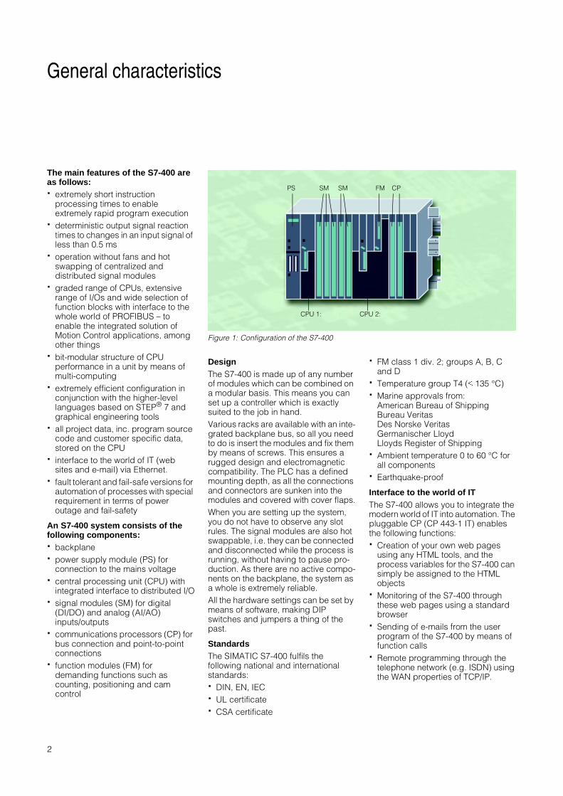
DesignThe S7-400 is made up of any number of modules which can be combined on a modular basis. This means you can set up a controller which is exactly suited to the job in hand. Various racks are available with an inte-grated backplane bus, so all you need to do is insert the modules and fix them by means of screws. This ensures a rugged design and electromagnetic compatibility. The PLC has a defined mounting depth, as all the connections and connectors are sunken into the modules and covered with cover flaps.When you are setting up the system, you do not have to observe any slot rules. The signal modules are also hot swappable, i.e. they can be connected and disconnected while the process is running, without having to pause pro-duction. As there are no active compo-nents on the backplane, the system as a whole is extremely reliable. All the hardware settings can be set by means of software, making DIP switches and jumpers a thing of the past.
StandardsThe SIMATIC S7-400 fulfils the following national and international standards: · DIN, EN, IEC · UL certificate· CSA certificate
· FM class 1 div. 2; groups A, B, C and D
· Temperature group T4 (b 135 °C) · Marine approvals from:
American Bureau of ShippingBureau VeritasDes Norske VeritasGermanischer LloydLloyds Register of Shipping
· Ambient temperature 0 to 60 °C for all components
· Earthquake-proof
Interface to the world of ITThe S7-400 allows you to integrate the modern world of IT into automation. The pluggable CP (CP 443-1 IT) enables the following functions:· Creation of your own web pages
using any HTML tools, and the process variables for the S7-400 can simply be assigned to the HTML objects
· Monitoring of the S7-400 through these web pages using a standard browser
· Sending of e-mails from the user program of the S7-400 by means of function calls
· Remote programming through the telephone network (e.g. ISDN) using the WAN properties of TCP/IP.
Figure 1: Configuration of the S7-400
CPU 1: CPU 2:
PS SM SM FM CP

3
Range of CPUs, multi-computing
Range of CPUsThere are a number of different CPUs with different performance levels which you can use to configure a programma-ble controller. · All the CPUs have a combined
programming and PROFIBUS-DP interface. This means they can be accessed at any time from the OP or programming device/PC or networked with various controllers. This interface can also be used for connecting distributed PROFIBUS-DP devices. This means that all the CPUs can be operated directly with distributed I/O.
· All the CPUs, except the entry level CPU 412-1, also incorporate a PROFIBUS-DP interface whose main function is to act as the interface to distributed I/O, but which can also be configured to be used for communications with the OP or programming device/PC.
· The higher-end CPUs also have free slots for PROFIBUS-DP interface modules in order to connect additional DP lines.
Otherwise, the only difference between the CPUs is the performance scope, e.g. RAM, address range, number of modules which can be connected and processing time.
Multi-computingMulti-computing, i.e. running more than one CPU in a S7-400 central controller, has a number of benefits to the user.· Multi-computing means that the
overall performance of an S7-400 can be split up. For example, complex technical functions, such as controlling, computing or communicating, can be separated and assigned to different CPUs. And each CPU can be assigned its own, local I/O.
· Multi-computing also enables different functions to be separated from one another, so, for example, one CPU can process the time- critical processing functions and another CPU the non-time critical functions.
In multi-computing mode, all the CPUs together act as a single CPU, i.e. if one CPU goes into STOP mode, all the other CPUs stop at the same time. Syn-chronization calls enable the actions of multiple CPUs to be coordinated for each individual instruction.At the same time, data transfer between the CPUs is extremely fast thanks to the “Global Data” mechanism.
Figure 2: CPU range for the S7-400
Address range in KB
Binary instruction processing time in Ns
Memory in MB
Number of blocks in K
4,0
3,2
1,6
0,75
0,25
0,1
0,2 0,1 0,0813816
8
4
16

4
Based on standard S7-400 modules, the S7-400H is a fault tolerant (redun-dant) PLC which drastically reduces the risk of production downtime. Its fault tolerant structure makes the S7-400H ideally suited to applications in which MTTR and downtimes need to be avoided where possible, e.g. for energy generation / distribution, the chemical industry, mining, transport, etc.
The fault tolerance is achieved by means of two parallel central control-lers whose CPUs are connected by means of fiber optic conductors and which control the redundant I/O via redundant PROFIBUS-DP lines. In the event of an error, there is a bumpless transfer of control, i.e. the intact standby device takes over execution at the point of interruption, with no loss of information.When setting up a fault-tolerant S7-400H controller, the user can con-centrate entirely on the job in hand: · The S7-400H is programmed in the
same way as a non-redundant standard S7-400 system using any STEP 7 language. All redundancy-specific functions can be configured using a easy-to-use STEP 7 option package.A program written for a standard non-redundant system can easily be ported to a redundant system (and vice versa).
· The S7-400H consists almost exclusively of standard components from the SIMATIC S7 range and is an integral part of Totally Integrated Automation® (TIA).
Further information can be found in the “SIMATIC S7-400H: the fault-tolerant power PLC” product brief.
S7-400H fault tolerant PLC
Figure 3: SIMATIC S7-400H fault tolerant PLC
Figure 4: Configuration of the SIMATIC S7-400H
Synchronization, information and status transfer
Process control
Centralized or distributed I/O, fault tolerant or standard
ET 200M Process control
Centralized or distributed I/O, fault tolerant or standard
Process control Higher availability of distributed I/O
S7-400H
Process
S7-400H
5
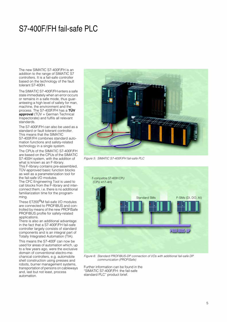
S7-400F/FH fail-safe PLC
The new SIMATIC S7-400F/FH is an addition to the range of SIMATIC S7 controllers. It is a fail-safe controller based on the technology of the fault tolerant S7-400H.
The SIMATIC S7-400F/FH enters a safe state immediately when an error occurs or remains in a safe mode, thus guar-anteeing a high level of safety for man, machine, the environment and the process. The S7-400F/FH has a TÜV approval (TÜV = German Technical Inspectorate) and fulfils all relevant standards. The S7-400F/FH can also be used as a standard or fault tolerant controller. This means that the SIMATIC S7-400F/FH combines standard auto-mation functions and safety-related technology in a single system. The CPUs of the SIMATIC S7-400F/FH are based on the CPUs of the SIMATIC S7-400H system, with the addition of what is known as an F-library. This F-library contains pre-assembled, TÜV-approved basic function blocks as well as a parameterization tool for the fail-safe I/O modules. The CFC Engineering Tool is used to call blocks from the F-library and inter-connect them, i.e. there is no additional familiarization time for the program-ming.These ET200®M fail-safe I/O modules are connected to PROFIBUS and con-trolled by means of the new PROFISafe PROFIBUS profile for safety-related applications.There is also an additional advantage in the fact that a S7-400F/FH fail-safe controller largely consists of standard components and is an integral part of Totally Integrated Automation (TIA).This means the S7-400F can now be used for areas of automation which, up to a few years ago, were the exclusive domain of conventional electro-me-chanical controllers, e.g. automobile shell construction using presses and robots, burner management systems, transportation of persons on cableways and, last but not least, process automation.
Further information can be found in the “SIMATIC S7-400F/FH: the fail-safe standard PLC” product brief.
Figure 5: SIMATIC S7-400F/FH fail-safe PLC
Figure 6: Standard PROFIBUS-DP connection of I/Os with additional fail-safe DP communication (PROFISafe)
F-compatible S7-400H CPU (CPU 417-4H)
Standard SMs F-SMs (DI, DO, AI)
6
Memory strategy, diagnostics
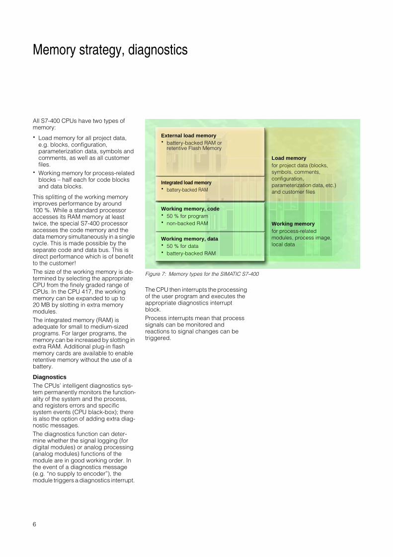
All S7-400 CPUs have two types of memory:
· Load memory for all project data, e.g. blocks, configuration, parameterization data, symbols and comments, as well as all customer files.
· Working memory for process-related blocks – half each for code blocks and data blocks.
This splitting of the working memory improves performance by around 100 %. While a standard processor accesses its RAM memory at least twice, the special S7-400 processor accesses the code memory and the data memory simultaneously in a single cycle. This is made possible by the separate code and data bus. This is direct performance which is of benefit to the customer! The size of the working memory is de-termined by selecting the appropriate CPU from the finely graded range of CPUs. In the CPU 417, the working memory can be expanded to up to 20 MB by slotting in extra memory modules.The integrated memory (RAM) is adequate for small to medium-sized programs. For larger programs, the memory can be increased by slotting in extra RAM. Additional plug-in flash memory cards are available to enable retentive memory without the use of a battery.
DiagnosticsThe CPUs’ intelligent diagnostics sys-tem permanently monitors the function-ality of the system and the process, and registers errors and specific system events (CPU black-box); there is also the option of adding extra diag-nostic messages.The diagnostics function can deter-mine whether the signal logging (for digital modules) or analog processing (analog modules) functions of the module are in good working order. In the event of a diagnostics message (e.g. “no supply to encoder”), the module triggers a diagnostics interrupt.
The CPU then interrupts the processing of the user program and executes the appropriate diagnostics interrupt block. Process interrupts mean that process signals can be monitored and reactions to signal changes can be triggered.
Figure 7: Memory types for the SIMATIC S7-400
External load memory· battery-backed RAM or
retentive Flash Memory
Integrated load memory· battery-backed RAM
Working memory, code· 50 % for program· non-backed RAM
Working memory, data· 50 % for data· battery-backed RAM
Load memoryfor project data (blocks, symbols, comments, configuration, parameterization data, etc.) and customer files
Working memoryfor process-related modules, process image, local data
7
CPUs — Integrated interfaces
In automation, there is a trend towards distributed systems.The required data transfer between the individual parts of the system means that communica-tions capability is taking on an increas-ingly important role. The SIMATIC S7-400 takes this into account: Interfaces integrated directly into the CPUs mean you can set up a high-performance communications environ-ment using conventional bus technol-ogy.
The programming interfaceAll CPUs have a combined program-ming and PROFIBUS-DP interface which can be accessed at any time by up to 125 programming devices/PCs or OPs and can also be networked with other controllers. This interface can also be used for connecting up to 31 distributed PROFIBUS-DP devices.· By means of data communication,
this interface enables the transfer of process data between various different controllers, e.g. one CPU can access the inputs or outputs of another CPU.
· The programming interface also has all the functionality of a DP interface.
PROFIBUS-DP interface (or “centralized = distributed”)In terms of configuration and program-ming, there is no difference between centralized and distributed I/O. To make setting up relatively large distributed structures economically viable, the SIMATIC S7-400 can be connected as a master to the PROFIBUS-DP open fieldbus (in accor-dance with EN 50170). This allows communications with a number of part-ners, from the SIMATIC controller to field devices from other manufacturers. Up to 125 stations can be controlled by one DP interface. More than 400 PROFIBUS slaves can be connected to a CPU with 4 interfaces; this means an S7-400 station can drive more than 1600 PROFIBUS slaves. It can also communicate with existing SIMATIC S5 or SIMATIC 505 systems without any problems. Firmware release V 3.0 and later (from July 2001) provides the S7-400 with even more networking functionalities. On the one hand, the S7-400 can now also be used as an intelligent slave on PROFIBUS-DP, permitting intelligent, distributed preprocessing. On the oth-er hand, following integration of the DP V1 functions according to IEC 1158 Parts 3-6, new, standardized PROFI-BUS-DP functions are now also avail-able in the S7-400 for communication with non-Siemens systems.Furthermore, the operating parameters of field devices can be modified during operation, thus reducing conversion times. Finally, expanded diagnostics functions facilitate troubleshooting and help reduce down times.
Shared functionsPG functions, e.g. programming by programming device/PC over long distances, are possible using either interface type. A programming device (PG) can also operate more than one CPU, or more than one programming device can access a CPU.There is also a routing function where-by a programming device connected to any point in the network can access all the stations on the network.HMI functionsHMI functions are already integrated into the operating system of the S7-400 and transfer data to connected SIMATIC Operator Panels or Operator Stations without the need for any pro-gramming.As with the PG functions, the control and monitoring functions are compati-ble with either the programming or the DP interface.To ensure safe control of the process, SIMATIC HMI® (Human Machine Interface) provides a complete range of innovative control and monitoring solutions. Push Button Panels, Text Dis-plays, Operator Panels, Touch Panels and multi-functional platforms based on Windows CE, plus PC-based display systems and process display systems to meet even the most exact-ing of requirements.For all panels in the SIMATIC HMI range, the configuration software used is SIMATIC ProTool/Pro® - a consistent, uniform, Windows-based system which accesses the STEP 7 database and thus avoids duplicate entries.More advanced functions, e.g. connection to bus systems, can be achieved using communications modules.

8
CPUs - Technical specifications
CPU 412-1 CPU 412-2 CPU 414-2 CPU 414-3
Working memory· integrated· in instructions· for program· for data
96 Kbyte32 K48 Kbyte48 Kbyte
144 Kbyte32 K72 Kbyte72 Kbyte
256 Kbyte84 K128 Kbyte128 Kbyte
768 Kbyte84 K384 Kbyte384 Kbyte
Load memory· integrated· expandable to
256 Kbyte RAM64 Kbyte
256 Kbyte RAM64 Kbyte
256 Kbyte RAM64 Kbyte
256 Kbyte RAM64 Kbyte
Backup Yes Yes Yes Yes
Number of blocks· FB· FC· DB
256256512 (DB 0 reserved)
256256512 (DB 0 reserved)
204820484096 (DB 0 reserved)
204820484096 (DB 0 reserved)
Program execution· free cycle· timed interrupts· delay interrupts· time interrupts· process interrupts· multi-computing interrupt· startup
1222213
1222213
1444413
1444413
Execution times· bit operations· word operations· fixed point arithmetic· floating point arithmetic
2 µs2 µs2 µs3 µs
2 µs2 µs2 µs3 µs
0.1 µs0.1 µs0.1 µs0.6 µs
0.1 µs0.1 µs0.1 µs0.6 µs
Bit memories/timers/counters· Bit memories· S7 timers/S7 counters· IEC timers/IEC counters
4 Kbyte256/256SFB/SFB
4 Kbyte256/256SFB/SFB
8 Kbyte256/256SFB/SFB
8 Kbyte256/256SFB/SFB
Design· Number of expansion units· Number of DP masters per CPU· Number of FMs
· Number of CPs
21max. 10limited by number of slots and number of connectionslimited by number of slots and number of connections
21max. 10limited by number of slots and number of connectionslimited by number of slots and number of connections
21max. 10limited by number of slots and number of connectionslimited by number of slots and number of connections
21max. 10limited by number of slots and number of connectionslimited by number of slots and number of connections
Programming interface· Number of stations· Transmission speed
16max. 12 Mbit/s
16max. 12 Mbit/s
32max. 12 Mbit/s
32max. 12 Mbit/s
DP interface· Number of stations· Transmission speed
32max. 12 Mbit/s
32 + 64max. 12 Mbit/s
32 + 96max. 12 Mbit/s
32 + 2 x 96max. 12 Mbit/s
Address ranges· Total I/O address area· I/O process image· Total digital channels· Total analog channels
4 Kbyte /4 Kbyte4 Kbyte /4 Kbyte32768/327682048/2048
4 Kbyte /4 Kbyte4 Kbyte /4 Kbyte32768/327682048/2048
8 Kbyte /8 Kbyte8 Kbyte /8 Kbyte65536/655364096/4096
8 Kbyte /8 Kbyte8 Kbyte /8 Kbyte65536/655364096/4096
MLFB group 6ES7412-1XF... 6ES7412-2XG... 6ES7414-2XG... 6ES7414-3XJ...
9
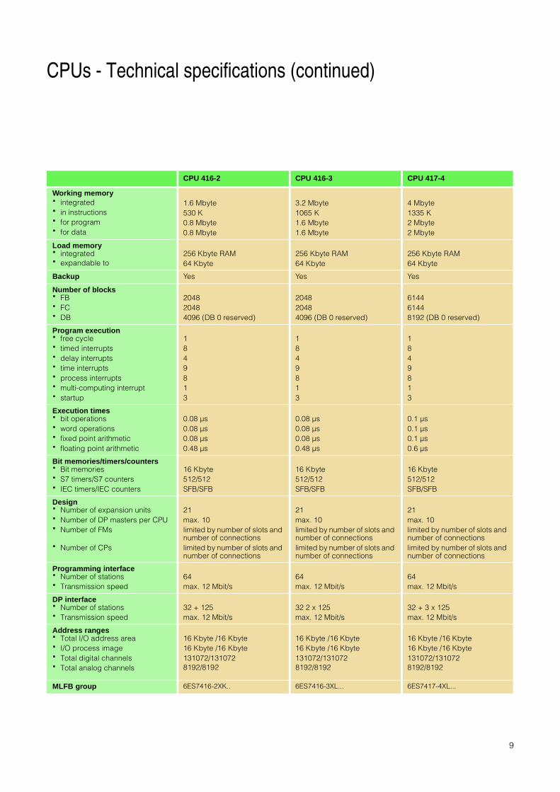
CPUs - Technical specifications (continued)
CPU 416-2 CPU 416-3 CPU 417-4
Working memory· integrated· in instructions· for program· for data
1.6 Mbyte530 K0.8 Mbyte0.8 Mbyte
3.2 Mbyte1065 K1.6 Mbyte1.6 Mbyte
4 Mbyte1335 K2 Mbyte2 Mbyte
Load memory· integrated· expandable to
256 Kbyte RAM64 Kbyte
256 Kbyte RAM64 Kbyte
256 Kbyte RAM64 Kbyte
Backup Yes Yes Yes
Number of blocks· FB· FC· DB
204820484096 (DB 0 reserved)
204820484096 (DB 0 reserved)
614461448192 (DB 0 reserved)
Program execution· free cycle· timed interrupts· delay interrupts· time interrupts· process interrupts· multi-computing interrupt· startup
1849813
1849813
1849813
Execution times· bit operations· word operations· fixed point arithmetic· floating point arithmetic
0.08 µs0.08 µs0.08 µs0.48 µs
0.08 µs0.08 µs0.08 µs0.48 µs
0.1 µs0.1 µs0.1 µs0.6 µs
Bit memories/timers/counters· Bit memories· S7 timers/S7 counters· IEC timers/IEC counters
16 Kbyte512/512SFB/SFB
16 Kbyte512/512SFB/SFB
16 Kbyte512/512SFB/SFB
Design· Number of expansion units· Number of DP masters per CPU· Number of FMs
· Number of CPs
21max. 10limited by number of slots and number of connectionslimited by number of slots and number of connections
21max. 10limited by number of slots and number of connectionslimited by number of slots and number of connections
21max. 10limited by number of slots and number of connectionslimited by number of slots and number of connections
Programming interface· Number of stations· Transmission speed
64max. 12 Mbit/s
64max. 12 Mbit/s
64max. 12 Mbit/s
DP interface· Number of stations· Transmission speed
32 + 125max. 12 Mbit/s
32 2 x 125max. 12 Mbit/s
32 + 3 x 125max. 12 Mbit/s
Address ranges· Total I/O address area· I/O process image· Total digital channels· Total analog channels
16 Kbyte /16 Kbyte16 Kbyte /16 Kbyte131072/1310728192/8192
16 Kbyte /16 Kbyte16 Kbyte /16 Kbyte131072/1310728192/8192
16 Kbyte /16 Kbyte16 Kbyte /16 Kbyte131072/1310728192/8192
MLFB group 6ES7416-2XK.. 6ES7416-3XL... 6ES7417-4XL...

10
Programming
The configuration and programming of the S7-400 is based on STEP 7. STEP 7 offers functions for every phase of an automation project – from configuration to startup, testing and servicing.
STEP 7STEP 7 incorporates the SIMATIC Manager, the central tool for the soft-ware-related handling of the project. This relates not only to a single CPU, but to the whole plant – irrespective of how many controllers, drives and HMI devices the solution consists of. Using STEP 7 also ensures that the data is kept consistent throughout the project. STEP 7 incorporates both the hardware configuration of the plant and the parameterization of the modules, so there are no more hardware settings to be made. STEP 7 also includes the three basic languages: statement list (STL), ladder diagram (LAD) and function block diagram (FBD). STEP 7 also makes it possible to parameterize high-speed data communications between networked CPUs.
Engineering toolsAs the S7-400 is generally used for executing large programs, there are also higher-level languages and graphical engineering tools based on STEP 7. These have the additional functionality to enable you to program automation solutions in a function-oriented manner and using a user-friendly interface.
The following tools are available for programming:S7-SCL(Structured Control Language), PASCAL-based higher-level language for programming SIMATIC S7/C7 controllersS7-GRAPHenables graphical configuration of sequential control systems for SIMATIC S7/C7S7-HiGraph®
for graphical description of sequential or asynchronous process with status diagrams for SIMATIC S7/C7CFC(Continuous Function Chart), the technology-oriented diagram which enables graphical interconnection of complex functions for SIMATIC S7
Data storageThe new STEP 7 Version 5.1 allows any data to be saved to the CPU, i.e. if you are servicing or upgrading the system, the personnel can still access not only the programs running, but also the whole project, including any comments and symbols. If you are using higher-level languages or graphical engineering tools, the program source code is also immediately available in its original form or in graphical format. Last but not least, it is also possible to save customer-specific operating instructions, manuals and machine documentation directly on the CPU in all standard file formats.
Figure 8: Memory required for engineering tools
Memory required
Productivity

11
Communication
Totally Integrated AutomationA single, completely integrated and consistent system with which you can execute any automation functions! An element of central importance within the system is the communications network:Industrial Ethernet (IEEE 802-3 and 802.3u) – the international standard for area and cell networking – with a connection to the IT environment.PROFIBUS (IEC 61158/EN 50170) – the international standard for the cell and field levels.AS-Interface (EN 50295) – the international standard for communi-cations with sensors and actuators.EIB (EN 50090, ANSI EIA 776) – the global standard building installation system and the basis for building services automation.Point to point connection – for communication between two stations with special protocols. The point to point structure represents the simplest form of communication. Various different special protocols are used (e.g. RK 512, 3694(R) and ASCII) (see also page 3).
Process or field communicationsProcess or field communication are used to connect actuators/sensors to a CPU. Process or field communication with the S7-400 is supported by PROFIBUS-DP. To make this possible, the S7-400 can be connected to PROFIBUS-DP as a master – either by means of the interface integrated into each CPU, a special interface module or a communications processor (CP). The AS interface and EIB networks and other bus systems are accessible from the S7-400 via the PROFIBUS gateways.
Data communicationsData communications enable data transfer between automation systems or between an automation system and an intelligent partner (PC, computer, etc.).This is achieved either through the programming interface or by means of PROFIBUS and Industrial Ethernet.
The programming interface enables simple cyclical data transfer on the one hand (no acknowledgment) and programmed transfer of relatively large volumes of data on the other (with or without acknowledgment). Specific
communications processors (CP) are used for the connection to PROFIBUS and Industrial Ethernet; which means that the TCP/IP protocol can be accessed direct from the program.
Figure 9: Communication options for the SIMATIC S7-400
PC OS
OSS7-300S7-400
S7-400Scanner
Network access
Link Link ET 200
Fire alarm Sensor

12
Range of modules
In addition to the range of specific S7-400 modules, the S7-400 also gives access to the world of PROFIBUS through the integrated PROFIBUS-DP interface. This means that a large num-ber of I/O modules are available with which the S7-400 can be adapted to a wide range of functions. Users of the system have access to PROFIBUS-DP modules from Siemens as well as modules from other manufacturers.
Naturally, there is also a wide range of S7-400 modules which can be used in central controllers and expansion units:· intelligent power supplies
(redundant, diagnostics-compatible) to secure the supply of all operating voltages
· digital and analog I/O modules for nearly all signal types, including some with interrupt processing and diagnostics
· function modules for counting/ measurement, all types of positioning functions, cam control, motion control and computing
· communications modules for serial point to point connection and bus communications by means of PROFIBUS and Industrial Ethernet
· interface modules for connecting expansion units to the central controller
The following documents contain additional information on the range of modules and on communications:· “Counting and positioning using
SIMATIC S7/C7” product brief· “Closed-loop control with
SIMATIC S7/C7” product brief· Flyer on “Point-to-point interface
modules” · Multimedia CD on “SIMATIC
technology … in action”· Overview of “Industrial
communications for automation”
· Leaflet on “FM 458 high-performance controller module
Expansion optionsNot only can a S7-400 system be expanded using PROFIBUS-DP, but additional racks can also be linked directly to the central processing unit. Distances of up to 600 m can be covered without any performance loss of the backplane bus. The power supply can also be looped through for shorter distances. Racks with 18 or 9 slots are available as the central controller. Using interface modules, up to 21 expansion units, each with either 18 or 9 slots for S7-400 modules, can be connected.
Communication Technology
Point to point connection with data rates of up to 115 Kbit/s and various protocols, e.g. for connecting modems, printers, scanners, drives, external devices, etc.
Counting in various modes, up to 500 kHz
Connection to PROFIBUS using either the DP or the FMS protocol (DP V0 and DP V1)
Cam control for up to 16 cam lines per module
Connection to Industrial Ethernet using the ISO/TCP or TCP/IP data communications protocol
Any type of positioning function: controlled positioning using the rapid/creep feed process (3 axes per module)
Connection to the Internet via Ethernet for loading websites and using e-mail
Point to point positioning and velocity profiles (position control) with stepper and servo motors (3 axes per module)
PID controller with backup functionality and integrated online self-configuration for various types of controller (continuous controllers, stepper controllers, pulse controllers)
Freely programmable, highly dynamic controller for up to 100 axes per module

13
I/O modules — Properties Selection aid for digital inputs/outputs
Signal modules are the interface between the SIMATIC S7-400 and the process. A wide range of different digi-tal and analog modules provide exactly the right inputs/outputs required for the function in question. However, the S7-400 signal modules represent only a subset of the modules which can be connected to the S7-400 via PROFIBUS-DP.
Easy to installThe sensors/actuators simply connect to the front connector. When replacing the module, all you need to do is plug the connector into the new module of the same type. You do not need to change the wiring. The coding of the front connector prevents confusing of modules. SIMATIC TOPconnect simplifies the wiring still further – with its pre-wired front connectors and terminal blocks.
High level of packaging densityThe large number of channels on the modules is one reason for the space-saving design of the S7-400: Modules are available with 8 to 32 channels (digital) or 8 to 16 channels (analog) per module.
Simple to configureThe modules are configured and parameterized using STEP 7, there are no fiddly switch settings. The data is stored centrally and automatically transferred to the new module after a module is replaced, which prevents transfer errors. No software upgrade is required when new modules are installed.
AlarmsMany modules also monitor signal acquisition (diagnostics interrupt) and
the signals from the process (process interrupt). This means the system can react quickly to any irregularities and to every process event. How and whether the controller reacts can be configured in STEP 7.For the digital input modules, a process interrupt can be triggered on a rising edge, a falling edge or both edges of a signal status change, or based on channel groups.
The following pages list criteria to help you select the appropriate signal module for a given application. Regularly updated, extensive technical information can be found in the interactive CA 01 catalog at any time (Internet: http://www.siemens.de/automation/ca01).
Module type Selection aid for digital inputs
Special features of this module
Very fast, interrupt- capable 24 V DC
input module
24 V DC standard input
module – extremely high
packaging density
Highest packaging
density for the 120 V market
Input module for higher, variable voltages
Interrupt-capable input
module for lower, variable
voltages
Specially for the US-domi-
nated AC market
channel-oriented isolation
Type of voltage DC DC UC UC UC AC
Input voltage 24 V 24 V 120 V 120/230 V 24 to 60 V 120 V
Interrupt capability Yes No No No Yes No
Number of channels 16 32 32 16 16 16
MLFB group 6ES7 421- 7BH..-...
6ES7 421- 1BL..-...
6ES7 421- 1EL..-...
6ES7 421 1FH..-...
6ES7 421- 7DH..-...
6ES7 421- 5EH..-...
Module type Selection aid for digital outputs
Special features of this module
DC output module for
high currents
DC output module for
variable voltages
24 V DC standard
output module – high poss. packaging
density
Very fast, interrupt-capable 24 V DC
input module
AC output module for high currents
and channel-oriented isolation
AC standard
output module
AC output module for
variable voltages
and channel-oriented isolation
Relay output module
Type of voltage DC DC DC DC AC AC AC Relay
Output voltage 24 V 20 - 138 V 24 V 24 V 120/230 V 120/230 V 20-120 V 5-125 VDC
Output current 2 A 1.5 A 0.5 A 0.5 A 5 A 2 A 2 A 5 A
Interrupt capability Yes No No Yes No No No No
Number of channels 16 16 32 32 8 16 16 16
MLFB group 6ES7 422- 1BH..-...
6ES7 422- 5EH1.-...
6ES7 422- 1BL..-...
6ES7 422- 7BL..-...
6ES7 422- 1FF..-...
6ES7 422- 1FH..-...
6ES7 422- 5EH0.-...
6ES7 422- 1HH..-...
14
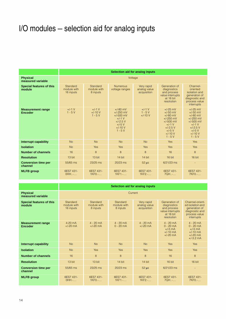
I/O modules — selection aid for analog inputs
Selection aid for analog inputs
Physicalmeasured variable
Voltage
Special features of this module
Standard module with
16 inputs
Standard module with
8 inputs
Numerous voltage ranges
Very rapid analog value acquisition
Generation of diagnostics and process
value interrupts at 16 bit
resolution
Channel-oriented
isolation and generation of
diagnostic and process value
interrupts
Measurement rangeEncoder
+/-1 V1 - 5 V
+/-1 V+/-10 V1 - 5 V
+/-80 mV+/-250 mV+/-500 mV
+/-1 V+/-2.5 V+/-5 V
+/-10 V1 - 5 V
+/-1 V1 - 5 V+/-10 V
+/-25 mV+/-50 mV+/-80 mV+/-250 mV+/-500 mV
+/-1 V+/-2.5 V+/-5 V+/-10 V1 - 5 V
+/-25 mV+/-50 mV+/-80 mV+/-250 mV+/-500 mV
+/-1 V+/-2.5 V+/-5 V
+/-10 V1 - 5 V
Interrupt capability No No No No Yes Yes
Isolation No Yes Yes Yes Yes Yes
Number of channels 16 8 8 8 16 8
Resolution 13 bit 13 bit 14 bit 14 bit 16 bit 16 bit
Conversion time per channel
55/65 ms 23/25 ms 20/23 ms 52 Ns 6/21/23 ms –
MLFB group 6ES7 431- 0HH..-....
6ES7 431- 1KF0.-....
6ES7 431- 1KF1.-....
6ES7 431- 1KF2.-....
6ES7 431- 7QH..-....
6ES7 431- 7KF0.-....
Selection aid for analog inputs
Physicalmeasured variable
Current
Special features of this module
Standard module with
16 inputs
Standard module with
8 inputs
Standard module with
8 inputs
Very rapid analog value acquisition
Generation of diagnostics and process
value interrupts at 16 bit
resolution
Channel-orient-ed isolation and
generation of diagnostic and process value
interrupts
Measurement rangeEncoder
4-20 mA+/-20 mA
4 - 20 mA+/-20 mA
4 - 20 mA0 - 20 mA
4 - 20 mA+/-20 mA
4 - 20 mA0 - 20 mA+/-5 mA+/-10 mA+/-20 mA
4 - 20 mA0 - 20 mA+/-5 mA
+/-10 mA+/-20 mA+/-3.2 mA
Interrupt capability No No No No Yes Yes
Isolation No Yes Yes Yes Yes Yes
Number of channels 16 8 8 8 16 8
Resolution 13 bit 13 bit 14 bit 14 bit 16 bit 16 bit
Conversion time per channel
55/65 ms 23/25 ms 20/23 ms 52 Ns 6/21/23 ms –
MLFB group 6ES7 431- 0HH.-....
6ES7 431- 1KF0.-....
6ES7 431- 1KF1.-....
6ES7 431- 1KF2.-....
6ES7 431- 7QH..-....
6ES7 431- 7KF0.-....

15
I/O modules — selection aid for analog inputs (continued)
Selection aid for analog inputs
Physical variable Resistance
Special features of this module
Standard module Numerous measurement ranges
High-speed analog value acquisition and generation of process
interrupts
Many measurement ranges and generation
of process and diagnostics interrupts
Encoder measurement range
0 - 600 8 0 - 48 8 �0 - 150 8 0 - 300 8 �0 - 600 8 �
0 - 6000 8
0 - 600 8 0 - 48 8 �0 - 150 80 - 300 8 �0 - 600 8 �
0 - 6000 8
Interrupt capability No No No Yes
Isolation Yes Yes Yes Yes
Number of channels 4 4 4 8
Resolution 13 bit 14 bit 14 bit 16 bit
Conv. time per channel 23/25 ms 20/23 ms 52 Ns 6/21/23 ms
MLFB group 6ES7 431- 1KF0.-.... 6ES7 431- 1KF1.-.... 6ES7 431- 1KF2.-.... 6ES7 431- 7QH..-....
Selection aid for analog inputs
Physical variable Thermocouples
Special features of this module
Standard module with 8 channels 16 channels with 16 bit resolution and generation of process and
diagnostics interrupts
Channel-oriented isolation and generation of process and
diagnostics interrupts
Types B, E, N, J, K, L, R, S, T, U B, E, N, J, K, L, R, S, T, U B, E, N, J, K, L, R, S, T, U
Interrupt capability No Yes Yes
Isolation Yes Yes Yes
Number of channels 8 16 8
Resolution 14 bit 16 bit 16 bit
Conv. time per channel 20/23 ms 6/21/23 ms –
MLFB group 6ES7 431- 1KF1.-.... 6ES7 431- 7QH..-.... 6ES7 431- 7KF0.-....
Selection aid for analog inputs
Physical variable Resistance thermometer
Special features of this module
Standard module with 4 channels Generation of process and diagnostics interrupts
Generation of process and diagnostics interrupts
Types Pt 100, Pt 200, Pt 500, Pt 1000,Ni 100
Pt 100, Pt 200, Pt 500, Pt 1000,Ni 100, Ni 1000
Pt 100, Pt 200, Pt 500, Pt 1000, Ni 100, Ni 1000
Interrupt capability No Yes Yes
Isolation Yes Yes Yes
Number of channels 4 8 8
Resolution 14 bit 16 bit 16 bit
Conv. time per channel 20/23 ms 6/21/23 ms –
MLFB group 6ES7 431- 1KF1.-.... 6ES7 431- 7QH..-.... 6ES7 431-7KF1.-....

Siemens AG Automation and Drives GroupIndustrial Automation Systems P.O. Box 4848, D-90327 Nuremberg Federal Republic of Germany
Siemens Aktiengesellschaft
© Siemens AG 2001Subject to change without prior notice
Order No.: 6ZB5310-0JD02-0BA3Printed in the Federal Republic of Germany26100/101638 MAN 09012.
I/O modules — selection aid for analog outputs
Information on thisproduct can be foundin the Internet at
http://www.siemens.de/simatic-s7
Selection aid for analog inputs
Physical measured variable Voltage, current
Encoder measurement range +/-10 V, 0 - 10 V, 1 - 5 V,+/-20 mA, 0 - 20 mA, 4 - 20 mA
Interrupt capability No
Isolation Yes
Number of channels 8
Resolution 13 bit
Conversion time per channel 420 Ns
MLFB group 6ES7 432-1HF..-....
All names marked in this product brief with ® are registered trademarks of Siemens AG. Other designations used in this document may be trade marks whose use by third parties for their own purposes could violate the rights of the owner.