for a better world - abb group · pdf filepower and productivity for a better world ... a...
TRANSCRIPT

… for a better world
2 / 2008
The corporate technical journal of the ABB Group
www.abb.com/abbreview
ABBReview
a
Tackling water shortages page 19
Weather forecasting page 39
Electrical transmission of the future page 52

ABB Review typically focuses on ABB’s products and technologies. The present issue takes a different approach and asks how these pro-ducts are affecting people and con-tributing towards a “better world.”
There is no single product or con-cept that alone can fulfill everybody’s idea of a better world. Rather, working towards this is about com-pleting a puzzle of many different pieces, each concerned with impro-vements in a particular area. This edition of ABB Review illustrates how the company is contributing to many of these puzzle pieces.

3ABB Review 2/2008
Editorial
Power and productivity for a better world – this is the essence of ABB.
ABB is one of the world’s leading suppliers of products and systems for electrical infrastructure, from house instal-lation to power generation, and for factory automation and optimization of industrial processes. Power and automation are two cornerstones of modern economies, the prosperity of which closely correlates with their ability to supply power in an efficient and reliable way and to continuously push productivity to world-class levels.
A reliable and cost-effective energy infrastructure enables industry to concentrate on its core competences and gener-ate value for society; the same is true of highly productive manufacturing processes. ABB is fostering “a better world” for the industrial members of society, which benefits us as individuals as well.
Internally, ABB is also striving for a better world, as sustain-ability issues drive company projects and extensive employ-ee safety programs are carried out. Our annual sustainabili-ty report provides a nice overview of all our efforts.
There are many ways in which ABB is also directly improv-ing individuals’ quality of life: A safe and reliable house installation, a well-functioning water supply, a comfortable train trip, a reliable elevator, a sunny seat in a football stadium and numerous other contributions are cultivating a better world. But while people in developed countries already feel uncomfortable when a train is not on sched-ule, there are more than one billion people who do not have access to the comfort of electricity at all. Clearly, the perception of “a better world” is very different across the globe.
ABB is proud to have a hand in developing a comfortable environment for everyone – in less developed societies and
in industrialized societies alike. The technology utilized is the same in many cases. In China, for example, the supply of electricity is provided by the world’s largest, most mod-ern and most powerful high-voltage direct current system from ABB. In Saudi Arabia, ABB recently installed modern desalination plants to produce fresh and healthy drinking water, and in Africa several projects are underway to pro-vide electrical infrastructure to local villages.
If “a better world” is related to an increasing gross domes-tic product that is generated in a sustainable way, the re-quired growth of energy consumption is – especially in the less developed countries – a major challenge for the global society. The efficient use of energy is therefore at the heart of almost all ABB products and systems. We want to create an infrastructure for a better and sustainable world – one that provides a level of comfort for all of us and at the same time does not deplete our resources or harm our environment. With this boundary condition, the comforts derived from ABB products can be enjoyed by everyone in all economies.
I invite you to discover in this issue of ABB Review how ABB is contributing to your quality of life. You may be surprised to learn how often ABB is the hidden source of comfort behind an application.
Enjoy your reading.
Peter TerwieschChief Technology OfficerABB Ltd.
... for a better world

A world of difference
6Better technology for a better worldAll around the world, people are plugging in to greater
comfort.
10Value-added comfortIntelligent building system technology is enhancing the
meaning of “flipping a switch.”
Bringing technology home
15Invisible safetyABB is hard-wiring safety into our homes.
19Breathing new lifeA stream of innovative technologies is helping quench
water shortages.
Moving ahead
25Performance on trackABB’s transformers and converters are just the ticket
for rolling comfort and flexibility into trains.
30Going up!ABB Review tells the uplifting story of a high
performance machinery drive for elevators.
34Smooth operatorCranes with brains are hoisting safety and performance.
Weather and leisure
39Watching the weatherWhen ABB talks about the weather, a cloud lifts over
many a forecaster.
43Moving more than goalpostsTouchdown! ABB drives and motor starters can adjust
the roof of a stadium, or even take the entire playing field
outside.
Simple and friendly
47The sound of silenceNoisy transformers don’t make good neighbors –
ABB is teaching them not to hum.
4 ABB Review 2/2008
ABB Review 2/2008… for a better world
Contents

52Light, safe and effectiveHVDC Light® cable systems are brightening the future
of power transmission.
Perpetual pioneering
56Success storyA helper in an orange coat hatched out of an egg
and rebuilt entire industries: ABB Review explores the
history of ABB robotics.
ABB Review 2/2008
6
15
25
39
www.abb.com/abbreview

6 ABB Review 2/2008
A world of difference
Better technology for a better worldElectricity makes life more comfortable – all around the globe Friedrich Pinnekamp
Comfort provides us
with the freedom to develop skills and capa-bilities to improve our quality of life. The percep-tion of comfort depends very much on a person’s
starting point: For those who once had to walk kilometers to fetch drink-ing water, comfort can be a running
source of fresh water at home. Similarly, for people who previously had to open their
blinds by hand, comfort can be opening the blinds with the touch of a button.
With a functioning infrastructure – for example, water supply or blind control – people can devote more time to devel-
oping further and finding creative means to-ward new levels of comfort. To foster this move toward
increasing comfort and with it the quality of life for everyone in the world, huge investments in reliable infrastructure are neces-
sary. ABB has a broad portfolio of products and systems to provide ma-jor parts of this infrastructure, especially in terms of power and productivity. With
its local presence in all parts of the world, ABB can directly respond to the different needs and so contribute to a better world.

7ABB Review 2/2008
Better technology for a better world
A world of difference
panels, and has been ex-tended to four more hamlets covering 500 households.
In ABB’s original Access to Electricity project in a Tan-zanian village, electrification has led to economic, social and environmental gains over the past two years 2 . A total of 15 businesses, in-cluding a guest house, food stores and clothes shops have sprung up in the vil-lage, compared with just three prior to electrification. Other recent advances in-clude:
25 new homes underscoring eco-nomic gains and local immigration
More homes connected to the mini-grid, based on the diesel generator donated by ABB, and a new water pump
Children who are able to study after dark are passing school exams in increasing numbers
Training on limiting hunting and sustainable logging
ABB partners with the global conser-vation organization WWF and local authorities on the project.
The supply of electricity to a remote hamlet in India also is helping people earn more and is facilitating children’s education. The hamlet’s inhabitants who are mainly tailors can now work longer and their children can also study at night.
larger contribution to people’s com-fort. However, to make this change, it is a necessary but not sufficient boundary condition1).
Successful projects As a provider of products and systems for modern electrical energy, ABB has long promoted the access to electricity in developing countries.
Following the successful launch of a rural electrification scheme in a re-mote location in southern Tanzania, the program was recently extended to Rajasthan in western India. The proj-ect – based on public–private partner-ships – has brought together ABB, the state government of Rajasthan and a non-governmental organization (NGO) to provide power to desert hamlets. The program started by providing one hamlet with power generated by solar
Every year, statistics are presented that rank the
nations according to their per capita income, and the spread of the scale is very wide, with a factor of more than 100 between the lowest and the highest income. Irre-spective of the absolute level of this income, the strive for growth and economic welfare is present everywhere.
The requirements for this ongoing growth are different, however, for the poor and the rich countries. 1 shows a schematic presentation of the gross domestic product (in pur-chasing power parity) and its connec-tion to the energy consumption per capita. Economies move from the lower left to the upper right in this presentation when measured over the years.
In the low-income economies (below $ 5,000 per capita), the growth of the gross domestic product (GDP) is al-most linearly connected to the energy consumption of the respective society. When industrialization with increasing need for energy takes off, the growing infrastructure increases the comfort of the people.
This trend continues until industrial-ization is close to complete. When, in economies above $ 15,000 per capita income, the growth shifts over to more value-adding from service, the increase in energy requirement is less pronounced, even though the growth of infrastructure (with lower energy need) is ongoing.
Among the different forms of energy used to provide a better infrastructure and increase comfort, electricity plays an extraordinary role. Electrical ener-gy can be used in almost all applica-tions to facilitate the lives of the people so that it has become the most versatile form of energy available. It helps to pump water, transport people, light hospitals and run medi-cal equipment, operate computers and mobile communication, energize factories, optimize production pro-cesses and heat houses. Electrical energy is the infrastructure making the
1 The coupling of energy production and gross domestic product
0 5 10 15 20 25 30 35
400
350
300
250
200
150
100
50
0
GDP/capita (in thousands of dollars)
Footnote1) Even with sufficient electrical infrastructure, life cannot be comfortable when other aspects of life are
unfavorable. War, disease, suppression or terrorism are only some important factors influencing the perceived
comfort of the individual.
2 Modern energy services to transform people’s lives [1]
Energy service needed Current energy options Modern erergy options
Lighting Oil/kerosene lamps Off-grid electricity (solar, hydro, wind)
Cooked food Wood/charcoal stoveImproved cookstoves/LP Gas and kerosene
Pumped water Surface/tube well Electric pumps
Refrigeration Grid/diesel power or nothing Off-grid electricity (solar, hydro, wind)
Telecommunications Grid/diesel power or nothing Battery charger/off-grid electricity
Transportation Human/animal-powered vehicles Motorized vehicles
Agro-processing Human/animal-powered devices Multi-functional platform/micro-hydro

8 ABB Review 2/2008
Better technology for a better world
A world of difference
danely, the opening of borders has resulted in the increasing demand for trains that work on different power supplies. ABB makes the trans-formers and converters of innovative trains that can – and do – go any-where.
The comfort of ships as a means of transport has increased dramatically as well. Ships equipped with ABB’s Azipod® and ABB turbochargers per-
available in Europe and the United States. Decades later, trains still started with a bump and jolt and one had to hold on tight not to be sent flying. ABB’s frequency converters make a world of difference in comfort today. Besides these frequency converters, ABB supplies many other train com-ponents. For example, ABB supplied the traction transformer that the TGV, the world’s fastest train, used on its record-breaking run. And more mun-
ABB has signed an agreement with the Chinese province of Guangdong, the country’s largest by GDP, to pro-vide advice about ways to improve the energy efficiency of companies in the region. The five-year agreement, signed in 2006, aims to help Guang-dong achieve its goal of reducing energy consumption by 16 percent per unit of GDP by 2010. The authori-ties will promote cooperation between ABB and more than 1,000 companies with high energy consumption. ABB will conduct energy conservation audits for companies that request them and help the companies to implement energy-saving measures. The energy saved can be used to increase the supply of electricity and the subsequent comfort.
Among the different forms of energy used to provide a better infra-structure and increase comfort, electricity plays an extraordinary role.
Comfort on a global scaleWhile ABB contributes with techno-logy to increase the comfort of people in the LDCs, it has a large portfolio of products and services to lift the perceived comfort of people in the emerging and developed economies.
Take transport, for example. A century ago, traveling comfort increased sig-nificantly when trains became widely
In July 2007, the United Nations Ministerial
Conference of the Least Developed Coun-
tries (LDCs) stated the following in connec-
tion with their meeting in Istanbul [1]:
“The energy challenges that underlie the
Millennium Development Goals (MDG)
achievement are best illustrated by the num-
ber of people who do not have access to
modern energy services. It is estimated that
worldwide there are 2.5 billion people who
rely on traditional fuels such as wood, char-
coal, and dung as their principal source of
energy for cooking and heating. Almost
1.6 billion people have no access to elec-
tricity. In light of these daunting figures,
energy’s important role in underpinning
MDG achievement is now being recognized
by the international development community.
This is due to the fact that energy is a pre-
requisite for meeting all of the MDGs be-
cause of its inherent linkage with poverty
alleviation, education, gender equity, health,
and the protection of the environment. Al-
though there is no MDG explicitly on energy,
it is now recognized that the MDGs cannot
be met without expanding access to afford-
able and reliable energy services for the poor
and unserved.
Factbox Access to electricity is crucial
“Energy is central to practically all aspects of
our lives, including access to water, agricul-
tural productivity, healthcare, education, job
creation, gender equality and environmental
sustainability. Yet, millions of households in
the developing world still lack access to safe
and reliable energy and pay high prices for
poor-quality substitutes. Moreover, poor peo-
ple spend much of their income on energy
services. This amounts to more than a third
of household expenditures in some countries.
They also devote a large portion of another
important asset, their time, to energy-related
activities – for example, women and young
girls spend upwards of six hours a day gath-
ering fuelwood and water, cooking, and agro-
processing. In Sub-Saharan Africa, only 8
percent of the rural population has access to
electricity while 90 percent of the population
still relies on traditional fuels for cooking.
“Having access to modern energy services
can make a real difference to poor people’s
lives 3 . Therefore, developing a new ap-
proach, where access to energy services is
acknowledged not just as an outcome, but
also as an actual driver of development, will
be crucial if energy is to play a more promi-
nent role in strategies aimed at achieving the
MDGs and making globalization work for the
LDCs.”
Millennium Development Goals (2000)
Goal 1 Eradicate extreme poverty and hunger
Goal 2 Achieve universal primary education
Goal 3 Promote gender equality and empower women
Goal 4 Reduce child mortality
Goal 5 Improve maternal health
Goal 6 Combat HIV/AIDS, malaria and other diseases
Goal 7 Ensure environmental sustainability
Goal 8 Develop a global partnership for development
3 Local shops are staying open longer in Ngarambe thanks to the extra four hours of
power provided daily by a generator.

9ABB Review 2/2008
Better technology for a better world
A world of difference
Protection against natural disasters is a basic human need. We want early warnings about the next big hurricane to save our lives. But also on a more indulgent comfort level, people might like to check the weather when they take vacations. Satellites equipped with ABB instruments are delivering better predictions. And satellites equipped with ABB interferometers are keeping a close check on air qual-ity as well. Like water, clean air is a comfort.
For many people, daily work is not only a necessary duty but also an en-riching life activity. The more creative people can be at work, the more com-fortable they feel. Again, technology is the key to providing a comfortable working environment. ABB automa-tion systems take away the burden of administrative efforts of operators and support the data analysis of com-plex processes. Robots help with more mechanical tasks and even the programming of robots is easier than ever before. Ultimately, it is technolo-gy, tools and versatile energy that provide people with the freedom to develop further – and that is comfort.
Friedrich Pinnekamp
ABB Corporate Research
Zürich, Switzerland
Reference
[1] Energizing the least developed countries to
achieve the millennium development goals: the
challenges and opportunities of globalization.
United National Ministerial Conference of the
Least Developed Countries Issues Paper, July
2007, Istanbul.
addresses in Dubai and the first smart home built in the Middle East 4 .
ABB’s i-bus EIB/KNX smart home system, which uses wireless touch screens, enables residents to control all the functions of their homes, in-cluding lighting, air conditioning, cur-tains and water heater temperature in any room, and from any room. The ability to control energy-intensive functions, such as air conditioning and lighting in each room, reduces power consumption and carbon diox-ide emissions, and makes it one of the most energy-efficient building automation systems on the market. It is one of the most widely used intelli gent installation systems in the world, and the leading smart building system in the Middle East and Africa.
As a provider of products and systems for modern electrical energy, ABB has long promoted the access to electricity in developing countries.
It’s not just about electrical power. ABB has numerous solutions for the management of other utilities. In the domain of water supplies, for exam-ple, ABB produces the drives that de-liver the right pressure as needed. The company also supports water utilities through a plethora of products ranging from humble flow meters to advanced process-control systems. And even if people in developed countries are used to it: Fresh water is a comfort.
mit journeys to be made faster and with less fuel. So whether you’re just waiting for goods, or maybe going on a cruise or even planning a polar expedition, ABB is keeping your ambitions afloat.
Another means of transport are eleva-tors. Modern elevators take comfort to a higher level. By eliminating bumps and jolts, ABB drives make elevators more comfortable, while at the same time reducing power consumption. But there is more to the story than boring office elevators – for example, a ship hoist that lets you take a boat trip across Canada.
With growing income, the demands on infrastructure are increasing. Elec-trical energy supply is no longer an issue in developed countries (if they can avoid blackouts), but the quality requirements of electricity are getting tighter. ABB’s contributions include silent transformers with an unprece-dented noise level and hidden advan-tages: Few people think overhead cables improve the landscape. ABB technology is making it possible to move them underground. Windmills too, are a controversial subject and are not appreciated by people who have them in their own backyards. Thanks to ABB technology, they can go out to sea and so not be seen.
The safety and automation level in building installations has reached a very high standard. ABB’s smart home automation system has taken luxury living to new heights in the award-winning 50-story Le Rêve (The Dream) Tower, one of the most exclusive
4 Le Rêve Tower in Dubai

10 ABB Review 2/2008
A world of difference
Value-added comfortIntelligent electrical installation technology makes living safer, life easier and the use of energy more efficientBernhard Doerstel
The networked home is not a vision of the future, rather it is reality, not least thanks to the intelligent house and building system technology of Busch-Jaeger Elektro GmbH. The ABB company offers innovative solutions and products allowing various home electrical systems to be flexibly connected and comfortably controlled via the existing electrical network. Atmospheric lighting, a constant comfortable temperature or monitoring of windows and doors are only some of the numerous functions provided by the system. Energy savings, simple installation and expandability provide added value in private homes as well as in commercial and public buildings, museums or hotels.
11ABB Review 2/2008
Value-added comfort
A world of difference
Modern times for a 1970s bungalowThe dream of a networked home is not reserved for new houses. It can also be implemented in older build-ings without affecting their architec-tural appearance. A successful combi-nation of state-of-the-art technology and 1970s architecture can be found in Ratingen near Düsseldorf in Germa-ny, where a bungalow was brought into the modern age with the help of innovative technology 3 .
Busch-Jaeger’s intelligent building system technolo-gy allows multiple electri-cal devices to interact wherever and whenever the user requires.
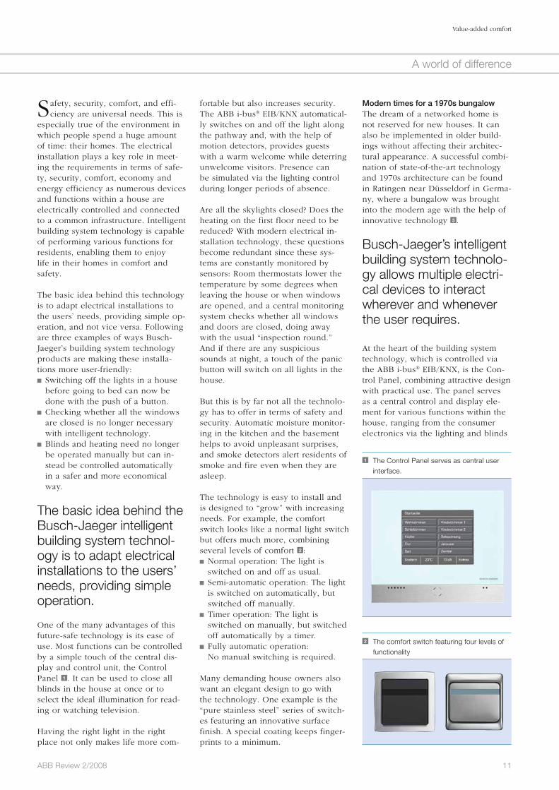
At the heart of the building system technology, which is controlled via the ABB i-bus® EIB/KNX, is the Con-trol Panel, combining attractive design with practical use. The panel serves as a central control and display ele-ment for various functions within the house, ranging from the consumer electronics via the lighting and blinds
fortable but also increases security. The ABB i-bus® EIB/KNX automatical-ly switches on and off the light along the pathway and, with the help of motion detectors, provides guests with a warm welcome while deterring unwelcome visitors. Presence can be simulated via the lighting control during longer periods of absence.
Are all the skylights closed? Does the heating on the first floor need to be reduced? With modern electrical in-stallation technology, these questions become redundant since these sys-tems are constantly monitored by sensors: Room thermostats lower the temperature by some degrees when leaving the house or when windows are opened, and a central monitoring system checks whether all windows and doors are closed, doing away with the usual “inspection round.” And if there are any suspicious sounds at night, a touch of the panic button will switch on all lights in the house.
But this is by far not all the technolo-gy has to offer in terms of safety and security. Automatic moisture monitor-ing in the kitchen and the basement helps to avoid unpleasant surprises, and smoke detectors alert residents of smoke and fire even when they are asleep.
The technology is easy to install and is designed to “grow” with increasing needs. For example, the comfort switch looks like a normal light switch but offers much more, combining several levels of comfort 2 : Normal operation: The light is switched on and off as usual.
Semi-automatic operation: The light is switched on automatically, but switched off manually.
Timer operation: The light is switched on manually, but switched off automatically by a timer.
Fully automatic operation: No manual switching is required.
Many demanding house owners also want an elegant design to go with the technology. One example is the “pure stainless steel” series of switch-es featuring an innovative surface finish. A special coating keeps finger-prints to a minimum.
Safety, security, comfort, and effi-ciency are universal needs. This is
especially true of the environment in which people spend a huge amount of time: their homes. The electrical installation plays a key role in meet-ing the requirements in terms of safe-ty, security, comfort, economy and energy efficiency as numerous devices and functions within a house are electrically controlled and connected to a common infrastructure. Intelligent building system technology is capable of performing various functions for residents, enabling them to enjoy life in their homes in comfort and safety.
The basic idea behind this technology is to adapt electrical installations to the users’ needs, providing simple op-eration, and not vice versa. Following are three examples of ways Busch-Jaeger’s building system technology products are making these installa-tions more user-friendly: Switching off the lights in a house before going to bed can now be done with the push of a button.
Checking whether all the windows are closed is no longer necessary with intelligent technology.
Blinds and heating need no longer be operated manually but can in-stead be controlled automatically in a safer and more economical way.
The basic idea behind the Busch-Jaeger intelligent building system technol-ogy is to adapt electrical installations to the users’ needs, providing simple operation.
One of the many advantages of this future-safe technology is its ease of use. Most functions can be controlled by a simple touch of the central dis-play and control unit, the Control Panel 1 . It can be used to close all blinds in the house at once or to select the ideal illumination for read-ing or watching television.
Having the right light in the right place not only makes life more com-
1 The Control Panel serves as central user interface.
2 The comfort switch featuring four levels of functionality

12 ABB Review 2/2008
Value-added comfort
A world of difference
The public areas of the four-star hotel make full use of modern electrical in-stallation technology, too. An impres-sive glass dome spanning the lobby, bar and gallery immerses the entrance area into a friendly light during the day. In the evening, different light scenarios create an inviting mood. These scenarios are controlled via the ABB i-bus® EIB/KNX and are activated depending on the time of day.
The ABB i-bus® EIB/KNX automatically switches on and off the light along the pathway and, with the help of motion detectors, provides guests with a warm welcome while deterring unwelcome visitors.
In nearly all areas of the Hotel de Saxe, Busch-Jaeger’s modern building system technology ensures comfort and provides atmospheric illumina-tion. The great ballroom, for example, features a dividing wall showing digi-tally edited alienated sights of Dres-den. As long as the wall is closed, the illumination of both parts is con-trolled separately; once the wall is opened, the switches on both sides of the wall control the lights in the entire room. Different light scenarios, for example for presentations or ban-quets, have been pre-programmed and stored allowing the right illumina-tion to be activated at the touch of a button.
The lighting and the sun protection as well as the projection screen are operated by easy-to-use control pan-els. A few labeled buttons ensure that even novice users can quickly and easily manage the various technical possibilities. In addition, interfaces to the audio-visual equipment enable lighting control from the lectern, allowing simultaneous operation of the projector and dimming of the lights. To comply with individual needs, all luminaire groups can be controlled both manually and via the pre-defined scenarios, and can be dimmed individually.
based on innovative building system technology from Busch-Jaeger. Special-ly designed luminaires and light bulbs put both the fresco and the staircase into the right light. The Busch-Jaeger Control Panel fits discreetly into even this special environment.
The illumination can be controlled automatically by means of signals from a meteorological station, or its intensity can be controlled individual-ly. This is particularly useful for offi-cial receptions and larger events, since a solemn atmosphere requires appropriate lighting. Besides a num-ber of other building functions, the technology also allows the ambient light atmosphere to be simply and quickly adapted to the respective situation.
Maximum comfort for travelersAfter 117 years, the Hotel de Saxe has returned to the Dresden Neumarkt, one of Europe’s most beautiful squares 5 . Favorably situated opposite the famous Frauenkirche, the hotel belonging to the Steigenberger group has recently opened. With the exterior modeled after the original design, the first-class hotel offers luxurious com-fort – with the help of modern build-ing system technology from Busch-Jaeger.
The interior architects wanted the room concepts to be carried over to the visible parts of the electrical in-stallation. After all, the switches for the hotel card and the lights are the first things a guest will notice when entering the room. The switches were selected from the Busch-Jaeger future® linear series whose unembellished design fits into the pure and subtle elegance of the Steigenberger house. The new hotel key card switch was used for the first time in this project.
to the presence simulation. The Con-trol Panel is complemented by the EIB sensor future® linear series, fitting perfectly into the modernized room concept.
The intelligent building system tech-nology allows multiple electrical de-vices to interact wherever and when-ever the user requires. Dimming the light, closing the blinds, starting the home theater – one system does all. The elegant touchscreen shows up to ten panels, which can be selected with the touch of a finger or using a PDA stylus. Even special light scenes can be stored and retrieved on de-mand, putting the entire property into the center of an atmospheric light composition.
Intelligent building system technology is capable of performing various functions for residents, enabling them to enjoy life in their homes in comfort and safety.
Putting art in the right lightBusch-Jaeger building system technol-ogy products can be found in numer-ous public and representative histori-cal buildings where they are used for the creation of atmospheric light scenes. In the Würzburg Residence, for example, the visitor is greeted by a truly “imperial” sight upon entering the staircase 4 : Up the white steps via the landing is the breathtaking, extensively restored fresco by the Venetian painter Giovanni Battista Tiepolo.
This unique eye-catcher is highlighted by a sophisticated illumination system
3 Modernized bungalow in Ratingen, Germany

13ABB Review 2/2008
Value-added comfort
A world of difference
area, it fits elegantly into the modern, functional interior architecture. In the main menu, the LCD shows the entire deck structure of the floating house from the lower deck to the sun ter-race.
The use of the panel is simple and intuitive: A touch of the screen directly leads to an overview of the indi vidual functions of the room showing the current conditions, such as temperature values, which can then be changed with a tip of the finger.
The ABB i-bus® EIB/KNX system forms the basis for the flexible networking and comfortable control of the lighting, heating, ventilation and safety/security equipment in the floating house.
Light, heating, cooling, time, tempera-ture, disturbance indication – the ver-satility of the Control Panel is un-matched. One of the functions that makes living in the floating house comfortable is the control of different light scenes. The main deck accom-modates the living area, including the winter garden, kitchen and bathroom as well as a sun deck, which can also be used as a jetty for a yacht. As all areas are amply equipped with light-ing elements, atmospheric light sce-narios can be programmed for every situation. While bright lighting is
ing low-energy house was launched. “Living on Water 1” is the first project of this kind to combine environmen-tally friendly construction methods, a regenerative energy supply and the modern installation systems of Busch-Jaeger 6 .
The residential building features a modern wood and glass construction and is carried by a floating steel body submersed in the water. The required energy is generated with the help of a roof-mounted photovoltaic plant, a heat exchanger beneath the floating house and a wood pellet oven located in the winter garden.
The heavily glassed “villa on the water” offers a year-round, unspoiled view of nature’s spectacles. The house fea-tures 140 square meters of covered living space, including outdoor terrac-es on three floors or decks. A modern interior and precious materials com-plete the clear design language of the exterior architecture.
The high standards placed on the fur-nishing are reflected in the building system technology, which – as speci-fied by the owner – was not to fall short of the standards offered by an exclusive land-based residential house. The ABB i-bus® EIB/KNX sys-tem forms the basis for the flexible networking and comfortable control of the lighting, heating, ventilation and safety/security equipment in the floating house.
Here again, the Busch-Jaeger Control Panel serves as a stylish control ele-ment. Centrally located in the kitchen
For maximum customer service, the system is connected to the Steigen-berger internal computer network via the EIB/LAN interface, making light control possible from every staff PC. Even in the kitchen the ABB i-bus® EIB/KNX is present. The individual areas from the starter station to the patisserie are subdivided into different luminaire groups, which can be switched individually. This helps to save energy since only certain areas are staffed and thus need to be illumi-nated at any given time. The same applies to the staircases and corridors, which are illuminated with differing intensity throughout the day.
With its building system technology, the Busch-Jaeger products not only round off the design in the Hotel de Saxe, but also ensure modern comfort and efficient use of energy behind historic facades.
A unique installation of Busch-Jaeger building system technology is located at the Kiel Fjord in northern Germany where the prototype of the first floatinglow-energy house was launched.
Technology for a floating houseA unique installation of Busch-Jaeger building system technology is located at the Kiel Fjord in northern Germany where the prototype of the first float-
4 The Würzburg Residence 5 Hotel de Saxe in Dresden

14 ABB Review 2/2008
Value-added comfort
A world of difference
room using the Busch-AudioWorld® system. The appropriate speaker com-ponents offer the highest stereo quali-ty in even the smallest rooms. The blending of architectural features and building technology in a spectacular setting as implemented in the “Living on Water 1” project has opened up new possibilities both aesthetically and technically.
Comfort includes efficiencyRising energy prices and the current climate discussion have increased the interest in energy savings. Modern building system technology plays an important role in this area as it allows, among other things, automated and efficient heating control.
ABB has developed many products and systems that offer new functional-ities while simultaneously increasing the user’s comfort. Flexibility and ver-satility are just two strengths of the Busch-Jaeger building system technol-ogy, which has successfully and gracefully illuminated new and old buildings alike, and has increased comfort, safety and security – effi-ciently.
Bernhard Doerstel
Busch-Jaeger Elektro GmbH
A member of the ABB Group
Lüdenscheid, Germany
Further reading
Rohrbacher, H., Struwe, C. Intelligent energy effi-
ciency. ABB Review 1/2008, 14–17.
Steiger, O., Bloch, R., Kramer, B., et al. Wireless
detection. ABB Review 4/2007, 70–73.
and changed for each room. In addi-tion, the temperature in the individual areas on deck can be controlled di-rectly using the room thermostats.
The intelligent building system tech-nology is able to detect energy-sav-ings potential even without any user input. Window contacts, for example, indicate open windows. In this case, the heating is reduced automatically to anti-icing level. With the help of the absence function, the system is shut down to a pre-determined value.
The technology is able to detect energy-savings potential even without any user input.
In addition to the central Control Panel, EIB sensors located in each room help to control the lighting, security equipment or consumer elec-tronics according to the residents’ needs. The single and multiple operat-ing elements feature inscribable, free-ly programmable, illuminated toggle switches. In the winter garden, for example, quadruple sensors offer numerous possibilities: While the upper four buttons can be used to control the lights, the lower buttons are for window control functions.
Finally, to complete this picture of comfort, music can be played in every
needed in the kitchen in the evening, the dining area and the winter garden are immersed in warm, indirect light, accentuated by ceiling-mounted lumi-naires above the dining table. In addi-tion, exterior luminaires on the glass facade and the terraces create a pleas-ant ambience.
This is only one of many possible scenarios that can be activated with the touch of a button on the Contol Panel. All functions, such as lighting, heating or home electronics, can also be operated with the remote control or the control elements on the devic-es. In addition, the multi-functional display and control device serves as a “notification center,” visually and acoustically indicating the triggering of security equipment such as motion detectors or window contacts.
At the same time, the security devices increase comfort: The motion detec-tors automatically switch on the light for residents coming home or guests visiting the floating house. The kitch-en area is illuminated upon entering as well, which is particularly conve-nient when arriving with no hands free to switch on the light.
When it gets cold, the floating house turns into a cozy home while the ABB i-bus® EIB/KNX and the Control Panel make sure that the heating is regulated efficiently and in line with the demand. The values can be indi-vidually displayed, pre-programmed
6 The “floating house” pilot project

15ABB Review 2/2008
Bringing technology home
One of the masterpieces of engineer-ing is the transformation of the poten-tially dangerous quantity we call elec-tricity into a completely safe everyday commodity. Most people are aware that touching a live wire carrying 220 V can be a painful experience. But despite the ubiquity of such wires in their homes, a very high level of pro-tection is provided. A sophisticated system ensures the safety of people, of the installation itself and of the entire building. The elegance and the significance of such installations are commonly hidden away in base-ments and broom closets, and behind plaster.
This article attempts to give the read-er a peek behind the scenes for an impression of the hidden technology that contributes to everyday well- being.
Invisible safetyElectrical installations in buildingsGuenter Schreiner, Gary Scardifield

16 ABB Review 2/2008
Invisible safety
Bringing technology home
old, the RCD immediately interrupts the current.
RCDs generally provide three kinds of protection: Basic protection. Normally this pro-tects people from electric shocks. It can be the insulation of a cable or the housing of an electrically oper-ated device or piece of equipment. If the basic protection is defective and someone touches the faulty part or if people deal carelessly with electricity, the RCD trips and inter-rupts the concerned circuit. In this case the RCD provides additional protection against electric shocks.
Fault protection. This protects the user if a high voltage occurs on the housing of the device. The RCD will switch off the concerned electrical circuit, preventing a person from touching the faulty device.
Preventative fire protection. This is needed if leakage current of an electrical line drains to the ground for some time. In this instance, an MCB would not switch off because the current is too low, even though this fault current might cause a fire.
protection. If a washing machine, for example, is protected by an individual MCB, a malfunction of the machine will lead to its disconnection. The supply of other devices, however, will remain unaffected, permitting them to continue operating. The more MCBs are installed for individual applica-tions, the smaller the effects of any individual incident.
ABB offers a wide range of products that con-tribute to the comfort, security, reliability and energy efficiency of customers’ electrical i nstallations.
Another advantage of MCBs is their reusability. Traditional fuses must be replaced after each operation, which not only means that every household must keep a stock of spare fuses, but also introduces a certain risk of the incorrect types being used. MCBs don’t have to be removed or replaced: A layperson can easily close the af-fected circuit by operating the toggle of the released MCB (of course after having addressed the problem, eg, by unplugging the defective appli-ance).
Well protectedResidual current devices (RCDs) rep-resent another indispensable type of protection device. In accordance with international and national standards in all EU countries, all socket outlets and mobile equipment for outdoors must be protected by RCDs. RCDs detect leakage currents, which leave an elec-trical line and drain to the ground even if the current is very small. Like an MCB, it also has a detection mech-anism for currents. When the leakage current rises above a certain thresh-
From time to time most people have had to go to the basement in
order to fix a fuse, probably unaware of the purpose of all the various ele-ments of the fuse and metering pan-els. There is a broad range of different building blocks that can be installed in a house. ABB, as one of the leading producers of devices and components for domestic and commercial appli-cations, offers nearly all necessary units 1 .
Prevention of excessive currentsOne of the most important and widely used units in the field of home and building protection is the miniature circuit breaker (MCB) 2 . MCBs are used for so-called line and fire pro-tection, ie, they protect buildings and appliances from the effects of short circuits and overloads.
For example, if the insulation of a cable is damaged and two copper lines touch, a short circuit is generated. This leads to a high current, which forces an MCB positioned further upstream to release immediately. The short-circuit protection is based on an electromagnetic trigger that opens the circuit and interrupts the current flow.
An MCB is also responsible for the protection of the connected lines themselves: The unit must be de-signed for the expected load of all connected devices. If there are too many devices or if they have too high a consumption, a permanent overload can ensue. Such an overload may be insufficient to qualify as a short cir-cuit, but can nevertheless cause the line to heat up, possibly resulting in a fire. Overloads of longer duration are detected by a thermal element inside the MCB that opens the circuit to pre-vent damage.
A broad and distributed use of MCBs increases what is called selectivity of
1 The full range of installation devices supplied by ABB
2 Internal mechanism of the miniature circuit breaker (MCB)

17ABB Review 2/2008
Invisible safety
Bringing technology home
ers) may be impossible. In such situa-tions, a relay switches off the device whose operation is long-term (storage heating) when the short-term device (ventilation heater) is used.
Energy consumption metersThese meters allow the separate mea-surement of the energy consumption of individual devices or parts of the building, for example an apartment in a residential building. They offer an easy overview on energy consumption and can contribute to a more efficient use of electrical energy.
Worldwide approvalThe safe, reliable and efficient infra-structure that is provided by domestic electrical installations is controlled by regional regulatory bodies all over the world. Before any of these devices can be released onto the market and installed in people’s homes, they must gain approval from the respective authority. ABB products, used by customers in almost all countries around the world, have obtained this approval and pro-vide the highest level of protection for the individual user 3 . But it is not on-ly the end user who benefits from this approval and standardization – the in-
the comfort, security, reliability and energy efficiency of customers’ electri-cal installations. These include:
Time switchesSelected sockets can be switched on or off automatically at definite times that are set by the customer.
Time relaysDifferent time functions can be realized, eg, automatic interruptions, delayed starts or cutoffs.
The safe, reliable and efficient infrastructure that is provided by domestic electrical installations is controlled by regional regulatory bodies all over the world.
Twilight switchesLights can automatically switch on or off in response to a selected level of ambient light.
Load-control relaysFor various reasons, the simultaneous operation of two powerful loads (eg, storage heating and ventilation heat-
Instead, the RCD switches of the concerned circuit.
The importance of selectivity applies here as well. A single RCD should not protect all sockets or all light circuits in a building, as all lights would go out in the event of a failure.
Preventing damage by voltage peaksHigh currents are not the only source of risk in electrical installations. Another source of danger lies in over-voltages: While the nominal socket voltage is 220 V or 110 V, sudden peaks of much higher voltages (but of very short duration) may occur. They can be caused by lightning, switching operations or enormous load changes in the grid. Such occur-rences can lead to the breakdown of insulation or cause damage to con-nected devices.
In fact, for electronic devices in com-mon commercial and residential us-age, overvoltages are the main cause of damage. Consequences of overvolt-age damage can range from malfunc-tions through loss of data to fire. Computers, printers, monitors, DVD players or TVs (to mention a few) are affected by these malfunctions and their number is continuously increas-ing.
ABB’s overvoltage protection devices limit voltage levels and switch voltage peaks to ground.
A whole range of devices for comfortBesides these special protection devices, ABB offers a wide range of additional products that contribute to
4 The Bundeskanzleramt in Berlin 5 Electrical installation securely placed in safe cabinets
3 ABB’s domestic installation devices fulfill a broad range of certifications from all over the world.

18 ABB Review 2/2008
Invisible safety
Bringing technology home
UK 500 consumer units can be supplied for flush or sur-face mounting. They can also be mounted in hollow walls, or partially recessed. With the addition of attractive door options in an interesting design, a technical product is created that meets the de-mands of décor and layout, not only blending ideally into its surroundings but also act-ing as an eye-catching focal point 6 . The wide range of modular wall-mounted, floor-standing, and switchgear cabi-nets enables each customer to select an individual and eco-nomical configuration.
Comfortable safetyThe best technologies are of-ten those that remain unseen because they behave exactly as the user intuitively expects, all the time and every time. ABB technology does precise-ly this. Whether people are watching a football match under floodlights, or shop-ping in a brightly-lit mall in an air-conditioned atmo-
sphere, ABB technology is providing safe and reliable electrical operation of building and residential infrastruc-ture.
Guenter Schreiner
ABB STOTZ KONTAKT GmbH
Heidelberg, Germany
Gary Scardifield
ABB Stiebel & John GmbH
Sasbach, Germany
cessfully operated in such demanding environments as hospitals, sports are-nas, shopping malls, banks or office buildings.
When it comes to safe installation in residential buildings, additional as-pects are appreciated by customers: These include the attractive appear-ance of cabinets if they are to be mounted in the living area of the house.
The best technologies are often those that remain unseen because they behave exactly as the user intuitively expects, all the time and every time.
The ABB UK 500 series consumer units fulfill these additional customer wishes. The units are marked by a harmonious interplay of design, ad-vanced technology and high-grade assembly to the highest quality. The
staller who fits the electrical installation into the building also benefits. The standard-ized installation technique using rail-mounted devices offers a high level of effi-ciency and robustness for the installation work.
Safety without compromise All the protection and meter-ing units mentioned above have to be installed in the building in such a way that even inexperienced or inat-tentive people are not en-dangered when they come into contact with the instal-lation. This is ensured by fixing the units to rails in a safe and standardized way, and in addition, by mount-ing these rails in immovable and closed cabinets.
Depending on the require-ments of the building that has to be supplied with electrical energy, these cabi-nets can reach a respectable size. 4 shows the building in Berlin in which the Ger-man chancellor is based – the Bundes-kanzleramt. To ensure a reliable elec-trical infrastructure, ABB has supplied the installation placed in the basement of the building 5 .
The type-tested low-voltage switch-gear assemblies (TTA), rated for up to 4,000 A, guarantee the very highest standards in terms of personal and plant safety, as well as of availability of the energy supply in a commercial and industrial environment. A unique advantage for the end user is the wide range of type-tested enclosures available, from 125 A for a small sub-distribution board up to 4,000 A for a main distribution in a TriLine-R switchgear cabinet. Combinations of enclosure and devices are put through their paces when type-tested to en-sure reliability and safety for the user. Such testing is documented by certi-fied and independent approval bod-ies. This not only ensures that instal-lations are fit for their purpose but also guarantees end users that their electrical installation is correctly dimensioned. ABB equipment is suc-
6 The front cover of a cabinet looks like a picture, permitting decorative placement in a house.

19ABB Review 2/2008
Bringing technology home
It covers two thirds of the Earth’s surface, comprises 75 percent of the human body and is one of the prime elements responsible for life on earth. Even though the percentage of the world’s water usable to humans is very small, there is actually enough water on the planet to satisfy the demands of a growing global popula-tion. However, an estimated one-third of the population currently lives in water-stressed countries, and by 2025 this estimate is expected to rise to two-thirds! One of the reasons for this is water quality. In many populated areas, exploitation and contamination have transformed usable water into a chemical cocktail unsuitable for human consumption or use. Another is the inefficiency in the way much of the water is used. Ineffective trans-portation and distribution systems also contribute to poor water access and increased water loss.
Using new and improved technology, ABB is supporting water utilities as they work to increase access to more usable water as well as reusing treat-ed wastewater.
Breathing new lifeWater supply technology is used to tackle the critical global problem of decreasing fresh water suppliesHeinrich-Martin Schreyer
20 ABB Review 2/2008
Breathing new life
Bringing technology home
is considered the most cost-effective desalination solu-tion, RO methodology is used in large applications today.
Desalination typically requires large amounts of energy and is often cited as an expensive solution, especially when compared with water pro-duction in treatment plants. Depending on the desalina-tion process used, the energy required consumes between twenty and sixty percent of the total production cost – RO being the least expensive process in terms of energy requirements and MSF the
most expensive. However, production costs in desalination plants during the last few decades have fallen by more than a factor of four. ABB has been working to reduce these costs even further by developing highly efficient electrical equipment.
It is not surprising that a large percentage of global desalination plants are located in the Middle East as rapid growth has increased the need for power and water services.
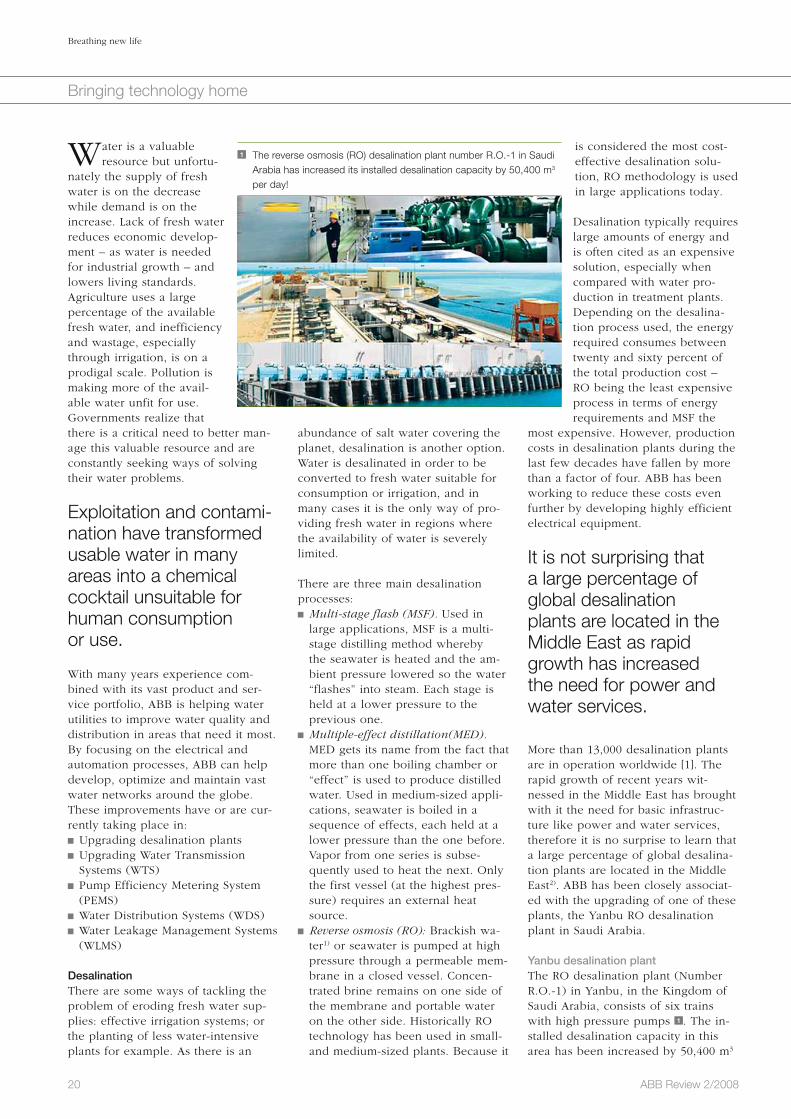
More than 13,000 desalination plants are in operation worldwide [1]. The rapid growth of recent years wit-nessed in the Middle East has brought with it the need for basic infrastruc-ture like power and water services, therefore it is no surprise to learn that a large percentage of global desalina-tion plants are located in the Middle East2). ABB has been closely associat-ed with the upgrading of one of these plants, the Yanbu RO desalination plant in Saudi Arabia.
Yanbu desalination plantThe RO desalination plant (Number R.O.-1) in Yanbu, in the Kingdom of Saudi Arabia, consists of six trains with high pressure pumps 1 . The in-stalled desalination capacity in this area has been increased by 50,400 m3
abundance of salt water covering the planet, desalination is another option. Water is desalinated in order to be converted to fresh water suitable for consumption or irrigation, and in many cases it is the only way of pro-viding fresh water in regions where the availability of water is severely limited.
There are three main desalination processes: Multi-stage flash (MSF). Used in large applications, MSF is a multi-stage distilling method whereby the seawater is heated and the am-bient pressure lowered so the water “flashes” into steam. Each stage is held at a lower pressure to the previous one.
Multiple-effect distillation(MED). MED gets its name from the fact that more than one boiling chamber or “effect” is used to produce distilled water. Used in medium-sized appli-cations, seawater is boiled in a sequence of effects, each held at a lower pressure than the one before. Vapor from one series is subse-quently used to heat the next. Only the first vessel (at the highest pres-sure) requires an external heat source.
Reverse osmosis (RO): Brackish wa-ter1) or seawater is pumped at high pressure through a permeable mem-brane in a closed vessel. Concen-trated brine remains on one side of the membrane and portable water on the other side. Historically RO technology has been used in small- and medium-sized plants. Because it
Water is a valuable resource but unfortu-
nately the supply of fresh water is on the decrease while demand is on the increase. Lack of fresh water reduces economic develop-ment – as water is needed for industrial growth – and lowers living standards. Agriculture uses a large percentage of the available fresh water, and inefficiency and wastage, especially through irrigation, is on a prodigal scale. Pollution is making more of the avail-able water unfit for use. Governments realize that there is a critical need to better man-age this valuable resource and are constantly seeking ways of solving their water problems.
Exploitation and contami-nation have transformed usable water in many areas into a chemical cocktail unsuitable for human consumption or use.
With many years experience com-bined with its vast product and ser-vice portfolio, ABB is helping water utilities to improve water quality and distribution in areas that need it most. By focusing on the electrical and auto mation processes, ABB can help develop, optimize and maintain vast water networks around the globe. These improvements have or are cur-rently taking place in: Upgrading desalination plants Upgrading Water Transmission Systems (WTS)
Pump Efficiency Metering System (PEMS)
Water Distribution Systems (WDS) Water Leakage Management Systems (WLMS)
DesalinationThere are some ways of tackling the problem of eroding fresh water sup-plies: effective irrigation systems; or the planting of less water-intensive plants for example. As there is an
1 The reverse osmosis (RO) desalination plant number R.O.-1 in Saudi Arabia has increased its installed desalination capacity by 50,400 m3 per day!
21ABB Review 2/2008
Breathing new life
Bringing technology home
multi-point to multi-point connections over several hundreds of kilometers, stretching from the supply side to the demand side. The water is collected from natural resources such as well fields, rivers or lakes, or from man-made resources, for example dams, water treatment or desalination plants.
trol system and the plant operation training simulator, to ABB. The project was completed in March 2007.
Water Transmission SystemsGetting the water to where it is need-ed is the job of a Water Transmission System (WTS). A WTS consists of
per day to a total capacity of approxi-mately 146,000 m3 per day. The com-plete desalination plant was contract-ed to the SBG-PCM division by the Royal Commission of Jubail and Yan-bu. SBG-PCM then subcontracted the main electrical parts, such as medium-voltage switchgear systems, transform-ers, low-voltage switchgear systems, motor control centers, the plant con-
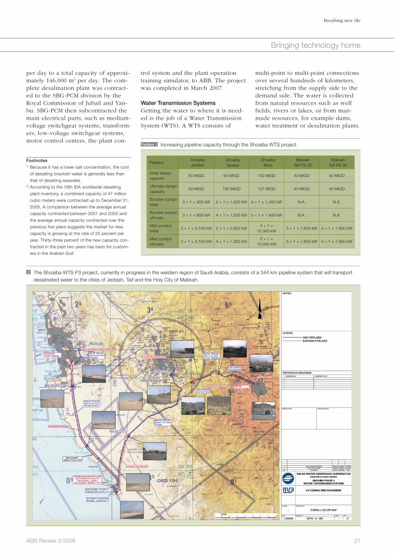
2 The Shoaiba WTS P3 project, currently in progress in the western region of Saudi Arabia, consists of a 344 km pipeline system that will transport desalinated water to the cities of Jeddah, Taif and the Holy City of Makkah.
Factbox 1 Increasing pipeline capacity through the Shoaiba WTS project
PipelineShoaibaJeddah
ShoaibaQuaiza
ShoaibaMina
MakkahTaif PS 2D
MakkahTaif PS 3D
Initial design capacity
60 MIGD 65 MIGD 100 MIGD 40 MIGD 40 MIGD
Ultimate design capacity
60 MIGD 130 MIGD 127 MIGD 40 MIGD 40 MIGD
Booster pumpsinitial
3 + 1 × 900 kW 2 + 1 × 1,500 kW 4 + 1 × 1,400 kW N.A. N.A.
Booster pumps ultimate
3 + 1 × 900 kW 4 + 1 × 1,500 kW 5 + 1 × 1,400 kW N.A. N.A.
Main pumps initial
3 + 1 × 3,100 kW 2 + 1 × 2,800 kW4 + 1 ×
10,300 kW3 + 1 × 7,800 kW 3 + 1 × 7,800 kW
Main pumps ultimate
3 + 1 × 3,100 kW 4 + 1 × 7,300 kW5 + 1 ×
10,300 kW3 + 1 × 7,800 kW 3 + 1 × 7,800 kW
Footnotes1) Because it has a lower salt concentration, the cost
of desalting brackish water is generally less than
that of desalting seawater. 2) According to the 19th IDA worldwide desalting
plant inventory, a combined capacity of 47 million
cubic meters were contracted up to December 31,
2005. A comparison between the average annual
capacity contracted between 2001 and 2005 and
the average annual capacity contracted over the
previous five years suggests the market for new
capacity is growing at the rate of 25 percent per
year. Thirty-three percent of the new capacity con-
tracted in the past two years has been for custom-
ers in the Arabian Gulf.
22 ABB Review 2/2008
Breathing new life
Bringing technology home
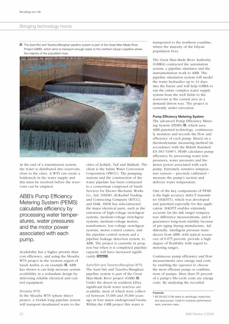
transported to the northern coastline, where the majority of the Libyan population lives.
The Great Man-Made River Authority (GMRA) contracted the automation system, a pipeline simulator and the instrumentation work to ABB. The pipeline simulation system will model the water hydraulics up to 14 days into the future and will help GMRA to run the entire complex water supply system from the well fields to the reservoirs at the coastal area in a demand driven way. The project is currently under execution.
Pump Efficiency Metering System The advanced Pump Efficiency Meter-ing System (PEMS) 4 , which uses ABB patented technology, continuous-ly monitors and records the flow and efficiency of each pump. Based on a thermodynamic measuring method (in accordance with the British Standard EN ISO 51983)), PEMS calculates pump efficiency by processing water tem-peratures, water pressures and the motor power associated with each pump. Extremely sensitive tempera-ture sensors – precisely calibrated – measure the pump’s suction and delivery water temperature.
One of the key components of PEMS is the high accuracy delta-T transmit-ter (HADTT), which was developed and patented especially for this appli-cation. HADTT enables extremely accurate (in the mK range) tempera-ture difference measurements, and it guarantees long-term stability because of pre-aging during manufacture. Ad-ditionally, intelligent pressure trans-ducers from ABB, with typical accura-cies of 0.075 percent, provide a high degree of flexibility with regard to metering ranges.
Continuous pump efficiency and flow measurements save energy and costs by enabling the operator to choose the most efficient pump or combina-tions of pumps. More than 95 percent of a pump’s life-cycle costs are energy costs. By analyzing the recorded
cities of Jeddah, Taif and Makkah. The client is the Saline Water Conversion Corporation (SWCC). The pumping stations and the construction of the water pipeline has been contracted to a consortium composed of Saudi Services for Electro Mechanic Works Co., Ltd. (SSEM), Al-Rashid Trading and Contracting Company (RTCC), and HAK. SSEM has subcontracted the major electrical parts, such as the extension of high-voltage switchgear systems, medium-voltage switchgear systems, medium-voltage motors, transformers, low-voltage switchgear systems, motor control centers, and the pipeline control system and a pipeline leakage detection system, to ABB. The project is currently in prog-ress but when it is completed pipeline capacity will have increased signifi-cantly Factbox 1 .
Sarir/Sirt and Tazerbo/Benghazi WTSThe Sarir/Sirt and Tazerbo/Benghazi pipeline system is part of the Great Man-Made River project (GMR) 3 . Under the desert in southern Libya significant fresh water reserves are available, most of which were collect-ed between 15,000 and 35,000 years ago in four major underground basins. Within the GMR project this water is
At the end of a transmission system, the water is distributed into reservoirs close to the cities. A WTS can create a bottleneck in the water supply and this must be resolved before the reser-voirs can be emptied.
ABB’s Pump Efficiency Metering System (PEMS) calculates efficiency by processing water temper-atures, water pressures and the motor power associated with each pump.
Availability has a higher priority than cost efficiency, and using the Shoaiba WTS project in the western region of Saudi Arabia as an example 2 , ABB has shown it can help increase system availability in a redundant design by delivering reliable electrical and con-trol equipment.
Shoaiba WTSIn the Shoaiba WTS (phase three) project, a 344 km long pipeline system will transport desalinated water to the
3 The Sarir/Sirt and Tazerbo/Benghazi pipeline system is part of the Great Man-Made River Project (GMR), which aims to transport enough water to the northern Libyan coastline where the majority of the population lives.
Footnote3) BS EN ISO 5198 refers to centrifugal, mixed flow
and axial pumps. Code for hydraulic performance
tests, precision class.

23ABB Review 2/2008
Breathing new life
Bringing technology home
of water put into the distri-bution system and the amount of water billed to customers. High levels of NRW result from losses that are real (though leaks) or apparent (through theft or metering inaccuracies).4)
The Bangkok metropolitan water system is one of the largest in the world. It sup-plies some 13 million peo-ple in Bangkok, Nontaburi and Samutprakarn with 1,628 million m3 of potable water a year via 24,328 kilo meters of pipeline over an area of 1,855 square kilo meters. However, the NRW level of the Metropol-itan Water Authority (MWA) was greater than 40 per-cent. This value needed to be reduced to a maximum of 30 percent and MWA called in ABB to help. ABB installed its water leakage management software (WLMS) which calculates water losses at 1,000 mea-suring points across Great-
er Bangkok, allowing leaks to be iso-lated and quickly corrected.
NeptuneAs fresh water supplies dwindle, new methods are needed to make use of the water that is available without the added burden of higher costs. In the spring of 2007, 11 companies and uni-
Holy City of Makkah. Using pumps or gravity, water is delivered from one DN 1600 suction line – with a pipe branch to the Arafat reservoir – into four possible discharge lines ranging in size from DN 800 to DN 1100. As the subcontractor, ABB was responsi-ble for the complete mechanical work, installation of electrical systems such as medium-voltage switchgears, medi-um-voltage motors, transformers, emergency power supply, low-voltage switchgears, instrumentation and an automation system, as well as the SCADA system for the pipeline net-work.
Water Leakage Management SystemOne of the major issues affecting wa-ter utilities in many developing coun-tries is “non-revenue water” (NRW), ie, the difference between the amount
pump efficiency, PEMS soft-ware proposes specific mainte-nance activity within a planned predicative and proactive main-tenance program.
As fresh water sup-plies dwindle, new methods are needed to make use of the water that is available without the added burden of higher costs.
Water Distribution SystemsWater Distribution Systems (WDS) are meshed networks with possibly thousands of kilometers of pipes. The water is collected from resources, water treatment or desalination plants. The end-point of a WDS is the service pipes that feed industrial and residential build-ings, farmlands or private households. In some areas two systems are installed: one serves agricultural industries and green lands with reused or fresh water, while the other distributes potable water for human consump-tion.
The target of an operational company is to continuously supply water in a defined quality at the lowest cost. To help companies – such as the Water and Sanitary Authority Makkah al Mukarramah in Saudi Arabia – met this target, ABB can increase pumping station availability through its design of a proper electrical and control system and by delivering reliable elec-trical and control equipment. ABB SCADA systems support operators by optimally running their water distribu-tion and irrigation, and service man-agers by keeping water leakages as low as is economically justifiable.
The Makkah Al Mukarramah pumping stationThe Makkah al Mukarramah pumping station 5 , completed in 2004, supplies drinking water to several reservoirs and water networks connected to the
Imperial College of Science, Technology
and Medicine
University of Sheffield
University of Exeter
The Chancellor, Masters and Scholars of
the University of Cambridge
Lancaster University
De Montfort University, Leicester
University of Leicester
Yorkshire Water Services Ltd
Engineering and Physical Sciences
Research Council (EPSRC)
United Utilities PLC
ABB
Factbox 2 The companies and universities involved in the NEPTUNE project
Footnote4) As well as real and apparent losses, NRW also
consists of unbilled authorized consumption which
can include water used for fire fighting or that pro-
vided to religious institutions. NRW is a key indica-
tor for the quality of a water distribution system.
4 ABB’s Pump Efficiency Metering System (PEMS) calculates pump efficiency by processing water temperatures, water pressures and the motor power associated with each pump.
Controller
Pressure Temperature
Suction side Delivery side
Electricpower
Temperature
high accuracydelta-T transmitter(HADTT)
InformationManagement

24 ABB Review 2/2008
Breathing new life
Bringing technology home
water utilities need to modernize and optimize their operation and mainte-nance activities. Effective automation systems and processes help reduce operation and maintenance costs and simplify cooperation between water supply installations over larger areas.
With its strong technology base and expertise, in particular in the areas of electrical systems and automation pro-cesses, ABB has an opportunity to achieve significant profitable growth in this market area. To support this aim, a strategical initiative was found-ed in the middle of 2007 to focus spe-cifically on technology implementa-tion, marketing and sales for the water market.
Water is effectively the source of life. Breathing new life into water plants helps to give and sustain this life.
Heinrich-Martin Schreyer
ABB Power Systems
Mannheim, Germany
Footnote5) The project is formally titled, “Delivering sustainable
water systems by optimizing existing infrastructures
via improved knowledge, understanding and tech-
nology – Project NEPTUNE.”
Reference
[1] Kranhold, K. (January 17, 2008). Water, Water,
Everywhere . . . , Seeking fresh sources, California
turns to the salty pacific, The Wall Street Journal.
versities Factbox 2 joined forces to work on a research project5) whose aim is to reduce the cost of water distribu-tion and to improve water supply quality. Known as the NEPTUNE proj-ect, it covers: Pressure and energy management Information management Decision support tools
The project has three main research priority areas (RPAs) Factbox 3 , each of which has individual work packages (WP).
With a growth rate of nine percent per annum expected in the global water market, water utilities will need to modernize and optimize their operation and maintenance activities. A growing marketThe global water market is expected to grow at a rate of nine percent per annum. Like any other plant facility,
RPA1: Sensors, data and knowledge
The aim of RPA1 is to develop pragmatic,
robust and novel methods and technolo-
gies (eg, sensors and communications,
and artificial intelligence and mathematical
simulation technologies) to understand
system performance in real time.
RPA2: Pressure management
The overall aim of RPA2 is to develop a
novel approach and practical tools for
pressure management to improve custom-
er service, efficiency and the sustainability
of water distribution systems, and to test
implementation concurrently with energy
management and leakage reduction.
RPA3: Risk-based decision support
The aim of RPA3 is to develop an integrat-
ed, risk-based decision support system to
evaluate intervention strategies (both tacti-
cal and strategic), which in turn aid deci-
sion making for sustainable water system
operation.
Factbox 3 The three main research priority areas (RPAs) associated with the
NEPTUNE project.
5 The Makkah al Mukarramah pumping station supplies drinking water to several reservoirs and water networks of the Holy City of Makkah.

25ABB Review 2/2008
Moving ahead
Today’s economy is dependent on the movement of goods and people. Without an efficient and affordable transportation system, people would have less choice in terms of what goods they could buy or where they could live and work. At the same time, this trans-portation is expected to have the lowest possible environmental impact. Electrical trains are well positioned to fulfill these demands. They offer large capacity, low energy consumption, minimal use of space, and quasi absence of pollution. No wonder that new railway lines are being built everywhere in the world, addressing on the one hand the need for high-speed city-to-city connections over some hundreds of kilometers as an alternative to air travel; and on the other hand urban transportation in growing metropolises that are more and more congested by cars.
In order to gain further market share against cars and airplanes, a reliable and safe railway service is primordial. Further reduction of travel time, increased comfort, and safety are crucial success fac-tors in further attracting patronage. This article presents some of ABB’s contributions to these goals.
Performance on trackElectric power products on trains – designed by ABB to make journeys more comfortableHarald Hepp, Fabiana Cavalcante, Peter Biller
When people ride a train, a metro or a tramway, only few ever
think of how the electric components on that vehicle determine their travel comfort. The first aspects that may come to mind in this respect are heat-ing, ventilation and air conditioning (HVAC), lighting, power supply for laptops and other onboard entertain-ment devices.
“Comfort devices” on boardThe power demand on trains and ur-ban-transit vehicles has risen constant-ly over the years. HVAC, automatic doors, passenger information systems, video surveillance systems or closed-system toilets have become a standard for new vehicles in most transport systems. These so-called auxiliary sys-tems today typically require a power supply capacity of about 400 to 800 W per seat.
On some special types of coaches or trains, this power demand is even higher: for example, kitchen equip-ment in a dining car or showers in a sleeping coach.
ABB BORDLINE® M auxiliary convertersWhat is ABB’s contribution to these features that add to passenger comfort in so many ways? Auxiliary power converters adapt the main electricity supply to the voltage and current needed for different groups of on-board applications. They belong to that class of utilities that people wish

26 ABB Review 2/2008
Performance on track
Moving ahead
tem is central in shortening travel times. ABB supplies the main electric components of an electric or diesel-electric propulsion system: motors, power electronics, high-power switch-es Factbox 1 , transformers, and genera-tors. A closer look at ABB’s transform-ers and compact converters shows how these components not only increase travel speed, but are also designed to cater to other aspects of passenger comfort: more space, less noise, more reliable schedules, travel without changing trains, safety.
ABB traction transformersThe transformer is a single transfer point for energy between catenary and motors, imposing the highest reliability demands. Any transformer breakdown would stop the train immediately (or run it at decreased speed if there is a second transformer in an independent propulsion chain). The transformer is thus highly relevant in terms of reliability and perfor-mance.
Convenient access and more spaceTraction transformers need to be of the smallest possible size since space is at a premium, especially in vehicles using the concept of distributed pro-pulsion (electrical multiple unit, EMU)
tion. ABB designs redundant supply and battery management systems that assure the continuity of the auxiliary power supply irrespective of short outages during train operations. For trains crossing borders between differ-ent line voltages, ABB provides multi-system auxiliary converters that auto-matically adapt to the voltage system. These are discussed in more detail later in this article.
Some of ABB’s auxiliary converters add to the traveler’s comfort in yet another way: They drive a tilting system for trains, which are able to run on winding tracks faster than conventional trains.
Shorter travel timesWith help of auxiliary converters, the traveler can enjoy those luxury ameni-ties on board that he or she is used to in everyday life (but cannot use in a car; for example, a laptop, bistro, a washroom or a bed). However, one of the most important factors that deter-mine the value of a journey or a short commuter trip is travel time – the shorter the better. High maximum speed is expected in long-distance travel while in urban transit one needs fast and smooth acceleration and braking. Clearly, the propulsion sys-
1 BORDLINE M30, a compact auxiliary converter for mounting on the roof of a light rail vehicle. It supplies power for numerous auxiliary applications.
2 A portfolio of examples of trains equipped with ABB traction transformers
to have but don’t wish to perceive. Such systems should not be heard, nor should they occupy space that could otherwise serve the passenger. Considerable progress has been made in increasing the power density of these devices, in developing a more compact design and in reducing the noise emissions of the necessary cool-ing and of the high-power switching devices. ABB BORDLINE® M auxiliary converters can be flexibly mounted under-floor, on the roof or even with-in the cabinet of other on-board pow-er devices 1 .
Auxiliary power on a transport vehicle should be available without interrup-

27ABB Review 2/2008
Performance on track
Moving ahead
close to the transformer. Besides safe-ty aspects, there are also limits on the resulting electromagnetic emission that have to be respected. This is tak-en into account in the design of the active part, the connections and the tank of the traction transformer. ABB’s advanced knowledge contributes to the shielding of the magnetic field, which is also applied to the design of traction converters.
Reduction of noiseAnother aspect of comfort is the mini-mization of noise emission. The pri-mary source of acoustic noise genera-tion in a transformer is the periodic mechanical deformation of the trans-former core and the winding coils under the influence of fluctuating electromagnetic fields. During a trans-former’s operation, the vibrations from its core and windings are trans-mitted to the transformer tank and its surface and then radiated as noise into the exterior air.
Several different means of noise reduction have been studied and can be implemented in ABB traction trans-formers. These include fixing the transformer to the vehicle through dampers that isolate the train against vibrations, using grain-oriented core
es the comfort, especially when travel-ing at high speed.
On a regional train, a cabinet the size of a cupboard can hold the propulsion converter, auxiliary converter, battery charger, line filter and the main switch for the power head.
Safety – invisible comfortTraction transformers and converters, along with other equipment on the train, have to fulfill strict safety stan-dards Factbox 2 . This is particulary true regarding fire and smoke. In the design of their oil-filled traction trans-formers (the oil is used for dielectric insulation and cooling), ABB takes great care to minimize the risk of fire in all imaginable situations. In the unlikely event of such an accident occurring nevertheless, the appropri-ate choice of materials ensures a mini-mization of risk to passengers’ health.
With under-floor or roof-mounted transformers, passengers may sit very
which has become dominant today. ABB has developed different solutions to this end, either placing the trans-former under-floor (typical for high-speed train applications, such as the new TGV generation in France, ETR 500 in Italy, or TALGO 350 in Spain) or mounting it on the roof of the vehicle (such as in Bombardier’s NINA, Alstom’s X60, or Stadler’s FLIRT trains) 2 . In both cases, the transform-ers need to be very flat, enabling a low floor design of the vehicle. Low floor translates into easier access, a big improvement especially for dis-abled passengers, or passengers trav-eling with bulky luggage, baby car-riages or bicycles. Faster access in turn enables lower dwelling times at stations, permitting faster services and better utilization of line capacity.
The transformer should be of lowest possible weight, as axle weight limits may typically not exceed 22.5 t or even more restrictively, 17 t for certain high-speed or narrow-gauge trains. Lower weight additionally means that less energy is needed to accelerate and slow down the train, hence assur-ing a better use of electrical power. The under-floor mounting of the heavy traction transformer lowers the center of gravity and thereby increas-
Medium-voltage (MV) vacuum circuit break-
er AC Trac is a further product in a train’s
traction chain that is essential for safety on
board. The newly launched MV circuit
breaker is installed on the roof of the vehicle
and can be used both for 25 kV / 50 Hz and
15 kV / 16.7 Hz applications. Its main func-
tion is to protect transformer, converters
and all other electrical components from
dangerous over-currents such as short
circuits, which are very often encountered
in railways.
Factbox 1 Medium-voltage vacuum circuit breaker AC Trac
Mountain railways have strict requirements
regarding safety, in particular for braking sys-
tems. In case of a power failure, mechanical
braking systems must stop the train. But the
mechanical brakes are not designed for use
during the whole descent from the mountain.
ABB’s Compact Converters in the rack-rail
vehicles for Bayerische Zugspitzbahn resolve
such an emergency situation with a special
braking control function: Since line voltage is
not available, the DC link is first charged us-
Factbox 2 Converter as an emergency brake for Zugspitzbahn
ing the vehicle battery. Then, the mechanical
brakes are released, the converters turned
on and finally, the motors start operating as
generators to brake the vehicle. In order to
stay in this operational mode, a minimum
speed is necessary to support the DC link
voltage of the converters, and hence me-
chanical braking must set in again to stop
the train on arrival at the final destination.
Passengers cannot perceive that this is an
emergency situation because the train rolls
down the mountain as usual.

28 ABB Review 2/2008
Performance on track
Moving ahead
software. The quality of the propul-sion converter control also has a direct impact on travel comfort: A traveler can easily distinguish a vehicle that accelerates impulsively or brakes jerkily because the converters do not perfectly control the motors. Travel continuity across bordersIn Europe, the railway line voltage changes at most of the country bor-ders, often even within one country.
generator (in diesel-electric propulsion) to feed and control the motors.
ABB has developed a wide range of so called BORDLINE®-CC compact converters that combine propulsion converters and auxiliary converters in one single device1). On a regional train, a cabinet the size of a cupboard can hold the propulsion converter, auxiliary converter, battery charger, line filter and the main switch for the power head. The very compact and modular design leaves more space to the passenger and is also most conve-nient for service 4 .
For light rail vehicles, ABB has de-signed a compact converter that can be mounted on the roof as well as under-floor – a very versatile con-struction which fits on various vehi-cles. It features two independent motor inverters and all the other components of a BORDLINE®-CC discussed above Factbox 3 .
Smooth rideAll ABB BORDLINE® compact convert-ers employ ABB’s standard industrial control platform AC800PEC2), leverag-ing cost-efficient long-term support and development. On this platform, simulations in MATLAB/Simulink can be directly translated to the control
steel with reduced magnetostriction, and stacking the steel sheets different-ly (step-lap technique). Also, the external cooling system of the trans-former could be a source of noise and therefore merits a high degree of attention in the design stage.
Besides technological leadership, ABB also enjoys a distinct market leadership position in traction transformers. Vari-ous types have been designed and delivered to practically all existing rail-way integrators and can be found ev-erywhere in the world and in all differ-ent applications (locomotives, high speed, EMUs). An ABB traction trans-former was installed on the latest TGV train from Alstom/SNCF that achieved the world-record speed for mainline railways of 574 km/h in April 2007 3 .
ABB compact converters Propulsion converters are an active link between the transformer and the mo-tors in AC trains. They not only supply the motors with exactly the voltage pat-tern that is needed in any moment of acceleration, constant speed or deceler-ation, but they also enable the vehicle to feed back energy to the line during braking. Other types of propulsion con-verters take a DC voltage input from the catenary (for DC railways, metros or tramways) or use the output of a
Input voltage: 420 – 900 V DC
2 independent motor inverters with the
following output power per motor:
Propulsion: 166 kW
Braking: 345 kW
Emergency brake: 535 kW
Auxiliary outputs with galvanic isolation: 3x 230/400 V 50 Hz, 35 kVA
3x 0…230/400 V, 0…50 Hz, 5 kVA
24/36/72/110 V DC, 8 kW
Size, weight 1600 x 1800 x 430 mm, 550 kg
Factbox 3 Technical data of ABB’s compact converter for LRVs 4a
4 Examples of BORDLINE®-CC compact converters for regional trains a and light rail vehicles b a
b
3 The Alstom/SNCF train with an ABB transformer on board setting the world-speed record. It reached 574 km/h on April 3, 2007.

29ABB Review 2/2008
Performance on track
Moving ahead
ABB is a well-known name in the railway
industry. While in 1996, ABB Transportation
Systems became part of AdTranz (a joint-
venture with Daimler-Benz that was later
sold to Bombardier), the production of
components (such as traction transform-
ers, converters and motors) was retained
by ABB. As the forerunner of what are now
called “Industry Segment Initiatives,” the
“ABB Railway Customer Segment RCS”
was created in 2005. Through implementa-
tion of a focused and coordinated business
approach to the railway market, and
through improved collaboration between
the different ABB-internal units involved, an
important business development could be
achieved: in 2007, ABB received more than
$ 700 million in orders from the railway in-
dustry, more than double compared to the
start of RCS. Today, ABB enjoys a clear
distinction in its market position as an inde-
pendent component supplier to most of
the world’s transportation system integra-
tors and vehicle manufacturers.
For rolling stock, ABB’s portfolio includes
traction transformers, converters, motors,
main MV breakers, power semiconductors,
surge arrestors and LV products.
For fixed installation, it includes complete
power substations, HV and MV products,
transformers, power quality solutions, fre-
quency converters, and communication
systems for signaling.
For more information, please visit
www.abb.com/railway
Factbox 4 ABB’s history in railways
types: one for operation in Switzer-land and one for Italy. Trains always had to stop at the Italian-Swiss border to change the locomotive. This proce-dure took a lot of time. Now, new FLIRT-type trains with ABB multi-sys-tem BORDLINE® compact converters permit this border to be crossed seam-lessly. Similar equipment has recently been ordered by Südtiroler Transport-strukturen for travel between Italy and Austria.
Reliability, punctuality, availabilityFinally, a fundamental aspect of com-fort in public transport should be em-phasized: the reliability of the service. The reliability and availability of elec-tric power products on trains have a fundamental impact on passengers’ comfort.
ABB, with its long experience in the railway industry Factbox 4 , not only defends its position as an innovative technology leader, but also puts a strong focus on reliability, quick ser-viceability, a rugged design, and a long-term commitment to vehicle manufacturers and railway operators.
Harald Hepp
Fabiana Cavalcante
ABB Automation Products
Turgi, Switzerland
Peter Biller
ABB Sécheron SA
Genève, Switzerland
Footnotes1) Such converters are further discussed in
“The compact converter,” ABB Review 3/2006,
pages 52–55.2) For further information on the AC800PEC,
please see “Design patterns,” ABB Review 2/2006,
pages 62–65. 3) 25 kV AC is used for most new high-speed lines in
the world. In many countries, trains may have to
additionally operate on networks electrified with
1,500 or 3,000 V DC.4) ABB’s traction-transformers for multi-system
trains are further discussed in “Trained to fit,”
ABB Review 3/2006, pages 49–51.5) FLIRT: “Flinker Leichter Innovativer Regionaler
Trieb zug” or “Fast Lightweight Innovative Regional
Train”; TILO: Treni Regionali Ticino Lombardia,
operator of cross-border regional trains between
Italy and Switzerland.
5 Stadler FLIRT TiLo crosses borders with ABB traction technology.
Networks in Finland, Hungary, Greece, Portugal, parts of France and the United Kingdom for instance are electrified at 25 kV / 50 Hz, as are many other countries in the world including China and India3). Mainline railways in Germany, Switzerland, Austria, Sweden and Norway are elec-
trified at 15 kV / 16.7 Hz. Poland, Bel-gium, Italy and Spain predominantly have 3 kV DC networks, which can also be found in South America and South Africa, while the Netherlands and Southern France are electrified at 1.5 kV DC.
Long-distance travel in Europe and regional travel in cross-border networks rely on the technical capacity of trans-formers and converters to adapt to different line voltages. It is a great ad-vantage in terms of passenger comfort to be able to remain seated (or bed-ded in a night train) when the train crosses borders between different electrical grids. Multi-system capability also considerably reduces travel time.
ABB has developed innovative multi-system solutions both for transform-ers4) and propulsion converters. Multi-system transformers can handle differ-ent input voltages and frequencies. The ABB multi-system front-end con-verter converts a DC input voltage to an AC voltage for the primary winding of an ABB multi-system transformer; this permits a regular AC BORDLINE®-CC compact converter to be used for both AC and DC input voltages.
The reliability and avail-ability of electric power products on trains have a fundamental impact on passengers’ comfort.
This converter is currently used in the regional trains “FLIRT” TILO5) serving the regions Ticino – Switzerland (AC 15 kV) and Lombardia – Italy (DC 3 kV) 5 . In the past, the rail operator TILO had two different locomotive
30 ABB Review 2/2008
Thema
Moving ahead
ABB’s new high performance machinery drive is making a big impact among end users and system integrators for original equipment manufacturers across a broad range of industries and demanding applications. Motala Hissar, a Swedish-based manufacturer of elevators to markets throughout Europe, is a case in point.
Faced with a technical difficulty that other drives vendors could not solve satis-factorily, Motala Hissar received a timely call from ABB. The result: the problem was solved within hours and Motala Hissar had a product that was “better, sim-pler and more competitive” than before.
Going up!Elevator manufacturer reaches new heights with ABB’s high performance machinery driveMatti Turtiainen, Mika Alakotila

31ABB Review 2/2008
Going up!
Moving ahead
The combination of these features brings considerable benefits to high volume machine builders in terms of engineering and final assembly, distri-bution and logistics, intellectual prop-erty protection and component re-placement Factbox 1 .
ABB has separated the main hardware and software functionality into three modules – a power electronics unit, a control electronics unit and a software memory unit.
The hardware modules (the power and control electronics units) can be delivered to the end customer as per the usual distribution schedules, while delivery of the memory unit can be delayed until the last moment. There is no need to incur travel costs by sending commissioning engineers – a local technician with basic drives training can simply plug in the memo-ry unit on-site. The number of prod-uct components and variants is mini-mal, and intellectual property rights for OEMs who develop their own con-trol functions are protected by encryp-tion. If the memory unit or one of the hardware modules fails to work, it is simply removed and a replacement plugged in.
Equipped with ABB’s Direct Torque Control technology, the high perfor-mance machinery drive can control any type of motor – synchronous or asynchronous, servo or high torque, in the 0.75 to 110 kW (1 to 150 hp) range – in open- or closed-loop mode. Designed to meet the high- volume needs of manufacturers and machine builders, as well as the appli-cation-specific requirements of indi-vidual customers, it combines the following main features into a highly versatile and cost-effective drive: Modular design Separate memory unit Unlimited functionality
Modular design ABB has separated the main hardware and software functionality into three modules – a power electronics unit, a control electronics unit and a software memory unit.
Separate memory unit The pre-programmed memory unit contains all the drive application soft-ware and parameter configurations in an easily replaceable, simple-to-install module.
Unlimited functionalityAlthough ready-made plug-and-play solution programs are available for most high performance machinery applications, the unique openness of the drive enables users to adapt and modify these programs to their precise needs.
Launched to industry acclaim in late 2006 at one of the key events in
the automation calendar – the annual SPS/IPC/Drives trade fair at Nurem-berg, Germany – the ABB high perfor-mance machinery drive has been quick to make a significant impact in a broad range of machinery applica-tions 1 .
The result of a three-year research and development program, the drive strengthens ABB’s portfolio of state-of-the-art frequency converters for low power ratings, while providing original equipment manufacturers (OEMs), system integrators and end customers alike with a uniquely flexible and powerful product that they can tailor to their precise requirements.
Equipped with ABB’s Direct Torque Control technology, the new drive can control any type of motor in open- or closed-loop mode.
The ABB machinery drive provides speed, torque and motion control for an extensive sweep of demanding applications. Industries in which the drive is already making a difference to customers’ operations include food and beverage, material handling, textiles, printing, plastics and rubber, and woodworking.
1 ABB high performance machinery drive
Compact modular design
3 separate modules for power electron-
ics, control electronics, and memory
Speed, torque and motion control
Separate memory unit for easy plug-and-
play installation
Programmable memory with unlimited
functionality
Ready-made programs available for most
machinery applications
Controls any type of motor in 0.75 to
110 kW / 1 to 150 hp rating
Open-loop or closed-loop control
Several plug-in options for I/O exten-
sions, motor feedback interfaces and
communication
Factbox 1 Drive features
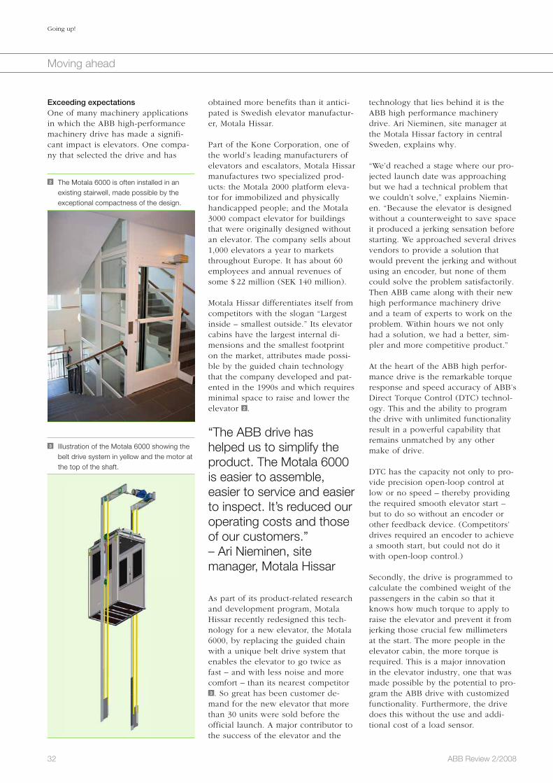
32 ABB Review 2/2008
Going up!
Moving ahead
technology that lies behind it is the ABB high performance machinery drive. Ari Nieminen, site manager at the Motala Hissar factory in central Sweden, explains why.
“We’d reached a stage where our pro-jected launch date was approaching but we had a technical problem that we couldn’t solve,” explains Niemin-en. “Because the elevator is designed without a counterweight to save space it produced a jerking sensation before starting. We approached several drives vendors to provide a solution that would prevent the jerking and without using an encoder, but none of them could solve the problem satisfactorily. Then ABB came along with their new high performance machinery drive and a team of experts to work on the problem. Within hours we not only had a solution, we had a better, sim-pler and more competitive product.”
At the heart of the ABB high perfor-mance drive is the remarkable torque response and speed accuracy of ABB’s Direct Torque Control (DTC) technol-ogy. This and the ability to program the drive with unlimited functionality result in a powerful capability that remains unmatched by any other make of drive.
DTC has the capacity not only to pro-vide precision open-loop control at low or no speed – thereby providing the required smooth elevator start – but to do so without an encoder or other feedback device. (Competitors’ drives required an encoder to achieve a smooth start, but could not do it with open-loop control.)
Secondly, the drive is programmed to calculate the combined weight of the passengers in the cabin so that it knows how much torque to apply to raise the elevator and prevent it from jerking those crucial few millimeters at the start. The more people in the elevator cabin, the more torque is required. This is a major innovation in the elevator industry, one that was made possible by the potential to pro-gram the ABB drive with customized functionality. Furthermore, the drive does this without the use and addi-tional cost of a load sensor.
obtained more benefits than it antici-pated is Swedish elevator manufactur-er, Motala Hissar.
Part of the Kone Corporation, one of the world’s leading manufacturers of elevators and escalators, Motala Hissar manufactures two specialized prod-ucts: the Motala 2000 platform eleva-tor for immobilized and physically handicapped people; and the Motala 3000 compact elevator for buildings that were originally designed without an elevator. The company sells about 1,000 elevators a year to markets throughout Europe. It has about 60 employees and annual revenues of some $ 22 million (SEK 140 million).
Motala Hissar differentiates itself from competitors with the slogan “Largest inside – smallest outside.” Its elevator cabins have the largest internal di-mensions and the smallest footprint on the market, attributes made possi-ble by the guided chain technology that the company developed and pat-ented in the 1990s and which requires minimal space to raise and lower the elevator 2 .
“The ABB drive has helped us to simplify the product. The Motala 6000 is easier to assemble, easier to service and easier to inspect. It’s reduced our operating costs and those of our customers.”– Ari Nieminen, site manager, Motala Hissar
As part of its product-related research and development program, Motala Hissar recently redesigned this tech-nology for a new elevator, the Motala 6000, by replacing the guided chain with a unique belt drive system that enables the elevator to go twice as fast – and with less noise and more comfort – than its nearest competitor 3 . So great has been customer de-mand for the new elevator that more than 30 units were sold before the official launch. A major contributor to the success of the elevator and the
Exceeding expectationsOne of many machinery applications in which the ABB high-performance machinery drive has made a signifi-cant impact is elevators. One compa-ny that selected the drive and has
3 Illustration of the Motala 6000 showing the belt drive system in yellow and the motor at the top of the shaft.
2 The Motala 6000 is often installed in an existing stairwell, made possible by the exceptional compactness of the design.

33ABB Review 2/2008
Going up!
Moving ahead
to elevator and escalator manufacturers worldwide. The ABB high performance machinery drive adds to this capability by enabling man-ufacturers to customize their own interface (with or with-out the help of ABB) and control any type of motor, or connect if needed to any type of feedback device or fieldbus. If the drive fails it can easily be replaced by a building attendant with basic electrical skills – all the ap-plication data is in the mem-ory unit.
ABB supports its drives cus-tomers with its own dedicat-ed service units and an ex-tensive ABB Drives Alliance global network. Special sup-port arrangements are avail-able for OEM customers, regardless of region.
Matti Turtiainen
ABB Drives
Helsinki, Finland
Mika Alakotila
ABB Automation Products
Mölndal, Sweden
smooth. There are no vibrations and no jerking starts and stops. It all adds up to maximum passenger comfort”Factbox 2 .
To reduce noise levels even more, Motal Hissar is evaluating ABB brake motors and considering using ABB circuit breakers and contactors. ABB supplies a complete range of power and automation products and systems
Thirdly, Motala Hissar built on this weight-sensing capability by developing a second fea-ture that differentiates the Motala 6000 from the compe-tition. Elevators are subject to stringent safety regulations. In most countries they are tested by independent inspectors at least once a year; in Spain – one of the customer’s main markets – they are inspected once a month. Inspection includes loading the elevator with large weights to ensure that it can safely operate at its maximum load. This is a cost-ly and time-consuming proce-dure. Motala Hissar has solved this by programming the ABB drive to simulate the test – and without using a load sensor – in a way that is acceptable to regulators. The savings in time and expendi-ture for Motala Hissar’s cus-tomers are significant.
“The ABB drive has helped us to simplify the product,” says Nieminen. “The Motala 6000 is easier to assemble, easier to service and eas-ier to inspect. It’s reduced our operat-ing costs and those of our customers. And we’ve got an elevator that goes twice as fast as our previous elevator model. These are all important selling points for our customers.”
“We tested the noise levels of different makes of drive and the ABB drive was the quietest.” – Ari Nieminen, site manager, Motala Hissar
Noise levels are lower than in the pre-vious elevator, an improvement made possible by a combination of both the belt drive technology and the high performance drive. “We tested the noise levels of different makes of drive and the ABB drive was the qui-etest,” says Nieminen. “Most impor-tantly, our customers are delighted with the new elevator and so too, according to our research, are passen-gers. The ride is fast, quiet and
Full torque at zero speed for
Smooth elevator start
Greater passenger comfort
Unique weight-sensing function
Open-loop solution (no encoders)
Unlimited potential for future functionality
Annual cost savings due to:
No feedback devices
No load cells
Benefits for own customers
Twice as fast
Easier weight tests
Fewer parts, less mechanical wear
Less maintenance
Factbox 2 Benefits for Motal Hissar

Smooth operatorCranes with brains make life comfortable for one and allMikael Holmberg
A 20-year old crane system may appear relatively modern, but technology has advanced so much over this period that improvements in positional accuracy, reduced mainte-nance and higher reliability can all be achieved. While these productivity improvements add to a system’s attractiveness, they are not the direct driving forces behind the pur-chase of crane systems. In the minds of a company’s Executive Committee, the overrid-ing concern is health and safety.
Throughout the world many crane systems are now out of date, something which could compromise the safety of crane drives and factory personnel. As zero accidents are the undisputed target, a modern crane control system needs to carry all the functionality that easily meets this goal.
ABB can help to achieve this. The company is recognized for its experience in designing and developing top quality products for crane applications. The combination of an ABB industrial drive and a newly developed crane control program is designed to meet the safety and performance demands placed upon a crane control system. With this combi-nation, the customer has a system that reacts much better than the one before.
34 ABB Review 2/2008
Moving ahead

35ABB Review 2/2008
Smooth operator
Moving ahead
accurate and soft control, which in turn avoids erratic movements of the load. A variable-speed drive, such as the ABB industrial drive, provides a good torque response, which is vital to load control 3 .
ABB’s crane control pro-gram, sometimes referred to as the “brains of the system,” is an optional easy-to-use software add-on for industrial drives.
Direct torque control One of the attractions of the ABB industrial drive is the performance offered by ABB’s motor control plat-form, known as direct torque control (DTC), and its inherent safety and protection functions. DTC allows accurate control of both speed and torque with or without pulse encoder feedback from the motor shaft. One
applica tions, using the mast modern technology including variable-speed drives and their associated software.
Comfort in the electrical departmentSandwiched between the expectations of the crane operator and that of the board of directors, the electrical engi-neering department undoubtedly faces the most demands. Not only is it con-cerned with the health and safety of the factory but it is also charged with maximizing productivity. Using a solu-tion that combines an ABB industrial drive with the newly developed crane control program, the electrical depart-ment can easily met these safety and performance demands.
Turning the old into the newThe modernization of older crane installations begins by looking at the type of motor used to lift the loads. Heavy duty AC slip-ring motors have been widely used in industrial crane drives and are available for currents up to 4,000 A. While effective in harsh environments, these motors do not have the torque and speed versatility1) of the more modern standard squirrel-cage induction motor 2 . When used with a low-voltage AC variable-speed drive, this induction motor provides
The phrase “trying to please all of the people all of the time” is a
tough call for any business. But that is precisely what ABB’s engineers had to consider when designing the latest version of the bespoke crane software for its range of ABB industrial drives 1 . Five very diverse customer types need to be satisfied when designing crane systems: the board of directors; the electrical engineering department; the maintenance department; the crane operator; and finally the factory floor personnel. The one demand each makes upon a control system is “comfort,” yet each has a very differ-ent comfort zone with little or no room for compromise.
One of the attractions of the ABB industrial drive is the performance offered by ABB’s motor control platform, known as direct torque control (DTC).
Comfort in the board roomThroughout the world many crane systems are now out of date. As health and safety concerns and the need to meet legal obligations top the list of priorities for most companies, a crane control system is needed that can accurately control the movement of the hoist without endangering the lives of the crane operator and other factory floor personnel. This means the system should be able to handle non-requested movements. In other words irrespective of whether the hook is empty or full, the crane con-trol system must be able to regulate speed and torque to respond to the maximum and minimum speed limits. However, it can cost tens of thou-sands of dollars to refurbish a large hoist crane, and determining a return on investment purely in terms of pro-ductivity improvements can be diffi-cult, if not impossible.
Therefore choosing the right company is imperative. Experience and know-how are essential if the required tar-gets are to be meet, and ABB has these in abundance. ABB is recog-nized for its experience in designing and developing products for crane
1 ABB is recognized for its experience in designing and developing products for crane applications.
Footnote1) If the torque of a suspended load is not controlled,
the load will swing and this could cause damage
through uncontrolled impacts.

36 ABB Review 2/2008
Smooth operator
Moving ahead
ABB has also invested heavily in the research and development of control panels to make the user interface as easy as possible. For maintenance engineers this manifests itself through the control panel, displaying clear text warnings and fault status’ so that immediate action can be taken 4 .
Comfort in the cabinFor a crane operator the ergonomics of the actual cabin are of the utmost importance. Clearly the need to sit in one place, often for long durations, demands a new design consisting of: comfortable and ergonomically correct operator seats; easily-cleaned hinged windows; air conditioning; and pneu-matic or electric wiper/washer sys-tems through to the temperature con-trol of the cabin. Safety, ergonomics and comfort are essential in ensuring optimum crane operator efficiency, and these are provided by: The joystick Braking Torque memory An anti-collision system
JoystickThe interface with the crane control system is mainly via a joystick and
thereby eliminating delays or risks, or communication errors.
For electrical engineers, ABB’s crane control program is extremely easy to start up, and this helps to keep total project costs under control. Multiple drives can be synchronized with an internal optical link, thereby reducing the need for separate controllers.
The crane control pro-gram supports remote monitoring and diagnos-tics by means of an intelligent ethernet module which provides access to the drive via the Internet.
Comfort in the maintenance departmentIn some industries, downtime can cost up to 1,000 euros per minute! There-fore reducing maintenance costs and finding highly reliable solutions are critical. The crane control program supports remote monitoring and diag-nostics by means of an intelligent eth-ernet module which provides access to the drive via the Internet. However, the biggest advantage to the mainte-nance department of a variable-speed drive solution is a reduction in overall maintenance costs because of less me-chanical wear and tear. When drives are installed on cranes, the mechani-cal wear becomes very small mainly due to their soft-start3) nature.
significant advantage of DTC is that it can achieve full torque at zero speed without any feedback device. It con-trols torque with an accuracy of one percent from zero speed through base speed without encoder feedback2).
DTC is ideally suited for use in crane control systems because it is designed for constant torque applications. A typical constant torque application is one where a load is suspended and the torque always remains the same – from zero to maximum speed and vice versa. As the load is lowered, the drive must constantly dissipate ener-gy. A four-quadrant drive is needed to ensure that as a 300-ton load is low-ered, energy can be fed back to the grid.
Crane control programTo further enhance crane safety and performance, ABB recently launched its crane control program as an op-tional, easy-to-use software add-on for ABB industrial drives. Some customers now refer to this program as the “brains of the system.”
While eliminating the need for exter-nal programmable logic control (PLC), this flexible and cost-effective soft-ware incorporates all the functions commonly required for hoist, trolley and long-travel motions in industrial harbor and tower cranes. A PLC would normally be used within the overriding control system to check the brake setting and the speed of the motor. However, the ABB industrial drive has a built-in PLC function,
2 Electrical engineers are embracing the torque and speed versatility benefits offered by standard induction motors in crane applications.
3 An ABB industrial drive provides a good torque response, which is vital to the control of the load in hostile crane environments, such as steelworks.
Footnotes2) However, for additional safety on hoist drives an
encoder can be used on the motor shaft to
measure the real position of the crane rather than
relying totally on the motor model. 3) Soft starters provide smooth and controlled starting
and stopping operations. They are used to avoid
rough and jerky motor starts, high starting currents
and torques, and high current and torque peaks.

37ABB Review 2/2008
Smooth operator
Moving ahead
to warn the crane driver. If, for exam-ple, the mechanical opening or clos-ing of a brake is problematic, a small proximity switch indicates the brake position. The operator receives a warning and is given sufficient time to react by safely lowering the load to the ground. Similar challenges arise when stopping the crane. If the brake is closed too soon, the load jumps. It is essential, therefore, to gradually and softly reduce the speed while maintaining full torque and then to close the brake. Once the brake is applied, the flux can be removed from the machine.
The crane system will automatically do a functionality check before any demands are placed on it. Checks are conducted on all electrical functions to make sure they are in good condi-tion as well as on the mechanical brake to ensure it is operating without slippage.
The crane control pro-gram contains a torque memory function that helps to provide safe and reliable mechanical brake control.
Anti-collision systemTo avoid collisions, cranes are fitted
ably. The mechanical brake is applied using a spring and is electrically re-leased when the drive system has been started and torque applied to the motor shaft. The software can accom-modate different start torque methods, and it also includes a brake monitor-ing function for start, stop or running sequences. Furthermore, low speed is required at the start of the lifting op-eration. When the motor is started, full torque is available and this must be controlled at low speed. To ensure precise and accurate movement of the load, the brake is opened and the speed is ramped up.
ABB’s crane control program also has an extended run-time feature. When the crane stops, flux remains on the motor (adjustable time). If this flux is not removed (through braking), the time taken to complete the next crane start up is considerably shortened be-cause there is no need for premagne-tizing.
Other features of the crane control program include the ability to check the position (open/close) of a mechan-ical brake. For example, when the line supply fails or is not available or when fuses blow, the brake must close. In other words a brake must operate effectively when no voltage is applied.
Additionally, ABB’s industrial drive also features good security measures
this is the lifeblood of a crane opera-tor. The joystick needs to be respon-sive, accurate and comfortable to use. ABB provides different types of joy-stick, and one such example is a four-step, potentiometer joystick which features push-button, radio and inde-pendent control.
From the moment the power is turned on, the operator expects the system to give an immediate and rapid re-sponse. In other words, when the joystick receives a speed reference, it should immediately move the crane hook4). ABB reckons the maximum tolerable delay before an operator becomes frustrated is 300 ms.
BrakingThe operator must also have confi-dence in the crane movements he is commanding. When starting the hoist, for example, braking is a must and not an option. A mechanical brake is used to hold the load firmly in place. When the drive starts the motor, there is a need to carefully order the release of the brake. If the brake is released too early, the load will fall uncontrol-lably. It is therefore essential to achieve maximum torque at zero speed, a role that belongs to the DTC. ABB’s crane control program assists in this area by using a function called torque memory.
ABB’s industrial drive and its crane control program are combined to meet the safety and performance demands placed upon a crane control system.
Torque memoryThe torque memory feature helps to provide safe and reliable mechanical brake control by being part of a sys-tem that ensures the hook does not drop during the start-up sequence. To be more specific, the integrated brake control logic utilizes torque memory and premagnetizing to open and close the mechanical brake safely and reli-
4 The simple user interface of the drives control panel means maintenance engineers can rapidly respond to warnings or changes in control performance.
Footnote4) This is achieved through an external 24 VDC to the
software boards.

38 ABB Review 2/2008
Smooth operator
Moving ahead
giving the impression of operating a different or even a “new” crane. In all likelihood, a new cockpit would speed up an operator’s adaption process. According to one customer, this ap-proach “can be more important than the drives. Because the crane operator loses his references and has to get used to a new control system, it can be beneficial to change the physical look and feel of the cab. Otherwise they say the crane is not working well when in reality it is much better.”
Comfort on the factory floorWith large diameter drums – weighing several hundred tons – suspended and moving above the factory floor, per-sonnel need to be assured that the load will not fall or swing violently. This assurance is given by employing variable-speed drives to accurately control the motor. The result is that loads can now accurately align slabs in blocks 5 .
With each crane revamp, ABB under-takes to provide a system that reacts better than the one before. Even though measurements are taken prior to and after a revamp, it is often the case that these are not needed as the improvements more than speak for themselves.
Perhaps it is possible to please all of the people, all of the time, after all!
Mikael Holmberg
ABB Drives
Helsinki, Finland
Operator satisfactionInstalling a new control system can sometimes lead to a psychological game between the crane designer and the operator. In many cases, an opera-tor is able to adapt his technique to compensate for any inefficiencies in a crane system with poor accuracy and responsiveness. The introduction of a new and highly responsive system (even with push buttons and joysticks familiar to the operator) often leads to operator discontentment.
There are two approaches in dealing with this problem. The first involves training operators on a crane fitted with an ABB drive. The second and perhaps the most convincing approach is to change the cockpit entirely. In essence, a new control system changes an operator’s feeling for the crane,
with an anti-collision system with limit switches at the end of the track. Colli-sion prevention is laser controlled and as the drive approaches the end posi-tions, the speed decreases, falling to zero if necessary. High- and low-limit sensors stop the drive at these end positions. The “slow down” safety control function limits the speed to a preset level in critical zones. In emer-gency situations, a “fast stop” safety control function is used.
A speed monitor function ensures that the crane motor speed remains within safe limits. A speed matching function continuously compares a speed refer-ence and the actual motor-shaft speed to detect any difference. One of these functions will stop the motor immedi-ately should a fault occur.
5 The benefits of a drive/motor-software combination from ABB is readily visible for crane operators and factory floor personnel alike.

39ABB Review 2/2008
Weather and leisure
Weather forecasts: We watch the television for them and search for them in newspapers. We listen to them on the radio and check them on the Internet – and even on game con-soles. The upcoming weather is an important factor in the planning of picnics or ski trips, in determining what clothes to wear or in ensuring our small talk conversations don’t run out of topics. Farmers rely on weather forecasting to plan their work schedule. Maritime fisher-men and sailors use weather maps to avoid the choppy seas and strong winds that can put the crew’s life in danger. The aviation industry is dependent on weather forecasting to determine when to issue de-icing procedures, to route the air traffic in order to improve fuel consumption efficiency of airplanes and avoid hazards related to environmental conditions. Power distribution companies rely on weather forecasts to anticipate the electrical demand for heating or air conditioning. Accurately predicting the course of a hurricane can help save lives. For a multitude of reasons, humans have a need to know what the weather will be in the upcoming hours and days.
Watching the weatherBetter weather forecasting for more safety and comfortLouis Moreau, Marc-André Soucy
Photo courtesy of NPOESS IPO

40 ABB Review 2/2008
Watching the weather
Weather and leisure
should not be confused with a fore-cast: By the time the analysis is com-pleted, the weather has already changed.
Weather analyses are used by meteo-rologists to feed numerical weather prediction models. These are mathe-matical models running on powerful computers. The models extrapolate the current weather pattern into the future in order to make predictions of meteorological conditions a few hours or days into the future.
Current and future instru-ments made by ABB will help to better understand the atmosphere of our planet and the complex chemical and dynamic processes taking place over our heads.
Predicting the weather is not simple. The atmosphere is a complex thermo-dynamical system and conditions can change rapidly. The accuracy of the prediction is limited by the accuracy of the weather analyses used as input and these are limited by the quality and the amount of collected meteoro-logical data. Within three days, the typical average accuracy of a weather forecast is between 60 and 80 percent. For predictions further into the future, the accuracy is reduced. The weather models also predict the average con-ditions over large areas (typically more than 1,500 km2). Of course, in reality, the weather is not uniform over the prediction area and this is another source of error. Sometimes, the output of numerical weather pre-diction models are “touched up” and adjusted manually by experienced me-teorologists in order to adapt the pre-dictions to account for the latest local measurements or for localized features that are not considered by the models. This is one of the reasons why predic-tions issued by different sources for the same region may differ.
ABB now offers a product to add to the array of instruments used to gath-er meteorological data. This instru-
two types of satellites used for weath-er forecasting. Some instruments are placed on geosynchronous satellites, ie, satellites orbiting at about 36,000 km of altitude, at the same rate the Earth rotates (the satellite remains fixed in the same place relative to the Earth). This allows instruments to constantly monitor a large area of the planet. Other instruments, placed on satellites at lower altitude (orbiting the Earth much more quickly), are used to col-lect data with a finer spatial resolution but not continuously; typically these instruments collect data of almost all locations on the planet twice per day. Generally, the meteorological informa-tion gathered from the current weath-er satellites is less accurate and coars-er than the information obtained from weather stations, but satellites provide information for nearly the entire globe.
Most countries freely share the meteo-rological information they gather. All these data are then assimilated by weather agencies and entered into standard grids to determine the actual weather patterns at a given time over the globe. Critical parameters need to be interpolated to compensate for the scarce density of measurements in some regions of the Earth. The best estimate of the current weather pat-tern at a specific time is called a weather analysis. A weather analysis
To issue local weather forecasts to end users, weather agencies need
information on the current weather patterns over large areas of the globe. Real-time measurements of tempera-ture, pressure, humidity, wind speed and direction, visibility and cloud cover are therefore necessary. Several parameters require not only data con-cerning conditions on the Earth’s sur-face, but also measurements of condi-tions at various altitudes.
Meteorological data are obtained at fixed locations by trained observers or automated weather stations on the ground or on sea buoys. Some weath-er stations – about 800 in the world – also use weather balloons carrying radiosondes to collect meteorological data from ground level up to 30 km into the atmosphere. Typically, each of these stations launches two bal-loons per day. Meteorological data are also obtained from commercial air-planes and from some ships.
Data obtained from weather satellites are also extensively used. Images tak-en from space are very useful in the observation of cloud patterns over the Earth and in determining the motion of air masses on a global scale. Instru-ments carried on satellites are also used to estimate surface temperature, humidity, cloud height, concentration of certain chemicals, etc. There are
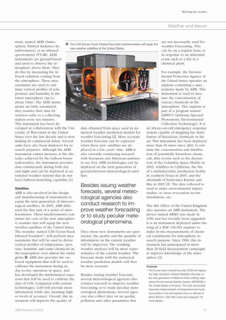
41ABB Review 2/2008
Watching the weather
Weather and leisure
are not necessarily used for weather forecasting. This can be on a regular basis or in response to an abnormal event such as a fire in a chemical plant.
For example, the Environ-mental Protection Agency of the United States operates an airplane containing a spec-trometer made by ABB. This instrument is used to mea-sure the concentration of various chemicals in the atmosphere. This airplane is part of a program named ASPECT (Airborne Spectral Photometric Environmental Collection Technology). It is
an always-on-call emergency response system capable of mapping the distri-bution of hazardous chemicals in the air. This instrument has been deployed more than 60 times since 2001 to esti-mate the concentration and distribu-tion of potentially hazardous chemi-cals after events such as the destruc-tion of the Columbia Space Shuttle in 2003, wildfires in California, the fire of a methylacrylate production facility in southern Texas in 2005, and the aftermath of hurricanes Katrina and Rita in 2005 [3]. The data collected is used to make environmental impact studies, to issue evacuation recom-mendations, etc.
The Met Office of the United Kingdom also operates an ABB instrument. The device named ARIES was made in 1996 and has recently been upgraded. It is an instrument deployed under the wing of a BAE 146-301 airplane to make in-situ measurements of chemi-cal constituents for atmospheric re-search purpose. Since 1996, this in-strument has participated in more than 20 field measurement campaigns to improve knowledge of the atmo-sphere [4].
data obtained from space used in nu-merical weather prediction models for weather forecasting [2]. More accurate weather forecasts can be expected when these new satellites are de-ployed in a few years’ time. ABB is also currently conducting research with European and American partners to see how ABB technologies can be deployed on the next generation of geosynchronous meteorological satel-lites.
Besides issuing weather forecasts, several meteo-rological agencies also conduct research to im-prove weather forecasting or to study peculiar mete-orological phenomena.
Once these new instruments are oper-ational, the quality and the quantity of information on the current weather will be improved. The resulting weather analyses will be more repre-sentative of the current weather: The forecasts made with the numerical weather prediction models will thus be more accurate.
Besides issuing weather forecasts, several meteorological agencies also conduct research to improve weather forecasting or to study peculiar mete-orological phenomena. Several agen-cies also collect data on air quality, pollution and other parameters that
ment, named AERI (Atmo-spheric Emitted Radiance In-terferometer), is an infrared spectrometer (FT-IR). AERI instruments are ground-based and used to observe the at-mosphere above them. They do this by measuring the in-frared radiation coming from the atmosphere. These mea-surements are used to esti-mate vertical profiles of tem-perature and humidity in the lower atmosphere (up to about 5 km). The AERI instru-ments are fully automated; they transfer their data by wireless radio to a collecting station every ten minutes. This instrument has been de-veloped in collaboration with the Uni-versity of Wisconsin in the United States over the last decade and is now making its commercial debut. Several units have also been deployed for re-search purposes. Although the AERI instrument cannot measure at the alti-tudes achieved by the balloon-borne radiosondes, the instrument provides data continuously during both day and night and can be deployed at au-tomated weather stations that do not have balloon-launching capability [1].
SatellitesABB is also involved in the design and manufacturing of instruments to equip the next generation of meteoro-logical satellites. In 2005, ABB deliv-ered the first unit of a series of inter-ferometers. These interferometers con-stitute the core of the new atmospher-ic sounder that will equip the new weather satellites of the United States. The sounder, named CrIS (Cross-Track Infrared Sounder)1), will perform mea-surements that will be used to derive vertical profiles of temperature, pres-sure, humidity and some chemicals in the troposphere over almost the entire globe 1 . ABB also provides the on-board equipment that will be used to calibrate the instrument during its day-to-day operation in space, and has developed the mathematical equa-tions that will be used to calibrate the data of CrIS. Compared with current technologies, CrIS will provide more information while also attaining high-er levels of accuracy. Overall, this in-strument will improve the quality of
1 The CrIS (Cross-Track Infrared Sounder) interferometers will equip the new weather satellites of the United States.
Footnote1) The Cross-track Infrared Sounder (CrIS) will replace
the High-resolution Infrared Radiation Sounder on
the next generation of National Polar-orbiting Oper-
ational Environmental Satellite System (NPOESS) in
the United States of America. The CrIS will provide
improved measurements of temperature and mois-
ture profiles in the atmosphere from an altitude of
about 850 km. Visit http://www.ipo.noaa.gov/ for
more details.

42 ABB Review 2/2008
Watching the weather
Weather and leisure
dioxide is one of the important green-house gases in the atmosphere that affect the climate of the planet.
The atmosphere is a com-plex thermo-dynamical system and conditions can change rapidly.
Current and future instruments made by ABB will help to better understand the atmosphere of our planet and the complex chemical and dynamic pro-cesses taking place over our heads. They will also provide better quality data to improve the accuracy of weather forecasting, hereby improving your chances of rain-free picnics.
Louis Moreau
Marc-André Soucy
ABB Bomem Inc.
Québec, Canada
References
[1] Feltz, W. F. et al. 2002 Near continuous profiling
of temperature, moisture, and atmospheric stabili-
ty using the Atmospheric Emitted Radiance Inter-
ferometer (AERI). J. Appl. Meteor.
[2] NOAA, NPOESS Instruments – CrIS, http://www.
ipo.noaa.gov/Technology/cris_summary.html
(January 2008).
[3] Kroutil, R. et al. Emergency response chemical
detection using passive infrared spectroscopy,
SPIE (http://spie.org/x8799.xml, January 2008).
[4] UK Met Office, Infrared interferometry using
ARIES, http://www.metoffice.gov.uk/research/obr/
radtran/ariesinstr.html, January 2008.
[5] CSA, SCISAT – From dawn to twilight,
http://www.space.gc.ca/asc/eng/satellites/scisat/,
January 2008.
[6] JAXA, Greenhouse Gases Observing Satellite
(GOSAT), http://www.jaxa.jp/projects/sat/gosat/
index_e.html, January 2008.
Footnote2) The Canadian SCISAT satellite is helping a team of
Canadian and international scientists improve their
understanding of the depletion of the ozone layer,
with a special emphasis on the changes occurring
over Canada and in the Arctic. The ACE-FTS instru-
ment on board SCISAT simultaneously measures
the temperature, trace gases, thin clouds, and
aerosols found in the upper atmosphere from an
altitude of 650 km.
A satellite of the Canadian Space Agency, SciSat, is also equipped with an ABB instrument 2 . Every day, it acquires about 2,700 high-resolution spectra of the upper atmosphere in the infrared portion of the electromag-netic spectrum. This instrument, named ACE, is primarily used to mea-sure the concentration of stratospheric ozone. This gas blocks most of the harmful ultraviolet radiations from the sun. The satellite was launched in 2003 and the instrument has operated flawlessly since. The data acquired by ACE has also helped to understand the chemical processes that lead to the generation and destruction of ozone in the upper atmosphere2) [5].
Next year, the space agency of Japan will launch a new satellite named GOSAT with an instrument that con-tains an interferometer made by ABB. This instrument will be used to moni-tor the sources of carbon dioxide near the surface of the Earth [6]. Carbon
2 The Canadian Space Agency’s SciSat satellite is equipped with the ABB ACE-FTS (Atmospheric Chemistry Experiment – Fourier Transform Spectrometer) instrument
Fourier Transform Spectrometers (FTS) mod-
ulate an incoming infrared beam in a wave-
length selective way by means of optical in-
terference. The intensity of the incoming light a is split in two parts by the half-mirror
beamsplitter (optical component b ). The re-
flected part travels two times the distance d1
separating the moving mirror c from the
beamsplitter. Similarly, the transmitted part
travels twice the distance d2 separating the
fixed mirror d from the beamsplitter. The
transmitted and reflected beams are superim-
posed in the output beam e where they in-
terfere with each other in either a constructive
or destructive way depending on the wave-
length of the incoming light and the distances
d1 and d2. By moving mirror c , the intensity
Factbox Fourier Transform Spectroscopy
at the output of the interferometer varies as a
cosine function as the interference goes
though a sequence of completely construc-
tive to complete destructive interference pat-
terns. In fact, the intensity of the modulated
output, also called the interferogram, for a
monochromatic light at wavelength λ (or fre-
quency ν ≡ c/ λ) entering the interferometer is
given by
where is the optical path
difference between the two arms of the
interferometer and I0
is the intensity of the
incoming monochromatic light. For a poly-
chromatic input, the total interferogram is
simply the sum of the monochromatic inter-
ferograms, ie,
where I0 (ν) is the spectrum of the polychro-
matic incoming light. The interferogram is thus
simply the Fourier Transform of the spectrum
of the incoming light. Therefore the spectrum
of the radiance entering the instrument can be
reconstituted by evaluating the inverse Fourier
Transform of the interferogram.
I(x;ν) = I0 cos(2πνx)
I(x) = ∫I0
(ν)cos(2πνx)dv
a
bc
d
e
d1
d2
x ≡ 2(d1 – d
2)

43ABB Review 2/2008
Weather and leisure
As professional sports venues become bigger and more complex in design and scale, architects and engineers are looking for bold new ideas. Retractable roofs have become a popular feature in such structures because they provide the ability to control the stadium’s interior environ-ment more effectively. Only a select number of companies have the knowledge and expertise to mecha-nize and control these immense structures, which, themselves, become architectural feats.
Moving more than goalpostsABB drives open and close the giant panels of a stadium roof – and motor starters move the playing fieldKen Graber

44 ABB Review 2/2008
Moving more than goalposts
Weather and leisure
sociated with running a roof on a sloped track,” says Nielsen 3 . “This caused us to look for a variable-fre-quency drive (VFD) that would allow us to test the drive torque before each roof motion, to ensure that each drive was operational and capable of a 100 percent torque output. The ACS800 was capable of this, so before each motion, the programmable logic con-troller (PLC) checks the torque output from the VFDs at 0 Hz, before commit-ting to opening the motor brakes.” Nielsen also says the ABB drives could be installed and operated without the need for closed-loop encoders – a cost-effective option that helped the company meet budget requirements.
The innovative roll-out field will save an estimated $50 million in operating costs, as it is more economical to move the field outside, than to retract the entire roof sufficiently to allow the necessary sunshine to reach the grass.
On the roofs that Uni-Systems had previously designed, if the motors didn’t start up for some reason when the brakes were released, the roof would simply remain in place. At the Cardinals’ new stadium – with its sloped roof track – such a situation could see the roof sections fall into the parking lot.
be closed to permit the facility to be air conditioned in the hot months, and then opened in the cooler months 1 . The roof’s panels consist of a PTFE (polytetrafluoroethylene) coated wo-ven fiberglass fabric, and are much lighter than a traditional, clad roof.
A moving playing surfaceThe stadium design includes not only a retractable roof, but also a retract-able playing surface 2 .
The innovative roll-out field will save an estimated $50 million in operating costs, as it is more economical to move the field outside than to retract the en-tire roof sufficiently to allow the neces-sary sunshine to reach the grass. The retractable, natural-grass playing sur-face is contained in a 16.9 million pound (7.7 million kg) tray that is 234 ft wide by 400 ft long (71 m by 122 m) – the first of its kind in North America. ABB motor starters activate the motors that retract the field. All in all, the de-sign of the stadium is so unique that it has featured in a multiple-part series on “The Discovery Channel.”
Direct torque controlThis roof was different from any that Uni-Systems had previously construct-ed. According to Lennart Nielsen, Danish master electrician and senior electrical designer with Uni-Systems, one of the most important decisions was selecting motor drives to control the roof’s movement. “An important factor in choosing the ABB drives was the inherent risks as-
Uni-Systems, based in Minneapolis, Minnesota, is just such an expert.
Whether it’s a retractable roof, a re-tractable pitcher’s mound, movable walls or seating, Uni-Systems has es-tablished itself as the industry’s pre-mier provider. The company’s impres-sive resume includes work on Minute Maid Park and Reliant Stadium, Hous-ton, Texas; Miller Park, Milwaukee, Wisconsin; RFK Stadium, Washington, D.C.; and most recently, the Arizona Cardinals’ stadium, Glendale, Arizona.
With its curved roof track, the Arizona Cardinals’ project presented fresh challenges in designing the retractable roof mechanism. Uni-Systems part-nered with ABB and selected the ABB ACS800 drive to provide optimum control of the roof’s torque-distribu-tion system.
An architectural oasis in the desertWhen, several years ago, the National Football League’s Arizona Cardinals decided to construct a new arena, the desert climate was a major consider-ation in the design plan. The heat can take its toll on fans and players alike, and can be detrimental to the playing surface – especially if it is natural grass. On the other hand, in cooler months, the world-famous climate is perfect for hosting outdoor activities.
The exterior design of the stadium resembles the basic form of the barrel cactus and was created by renowned architect Peter Eisenman, together with the sports architecture company, HOK Sport. The retractable roof can
1 The retractable roof on the new Arizona Cardinals’ stadium in Glendale, Arizona is powered by ABB ACS800 Drives.
2 The entire playing surface can be rolled out of the stadium.

45ABB Review 2/2008
Moving more than goalposts
Weather and leisure
communications network between each group of eight VFDs, where one VFD was designated as master and the other seven as followers.”
Once the roof is moving, it is ex-tremely important to keep a very tight torque-and-speed envelope around each follower drive in relation to each roof quadrant’s master VFD,” Nielsen continues. “The ultra-fast switching Direct Torque Control system of the ACS800 provides the means for doing this via the fast intra-VFD fiber-optic network.”
The PLC issues a speed (frequency) command to each of the two master VFDs (one per side) and the seven follower drives then match the torque output of the master drive. Each roof panel’s PLC handles the position alignment between the two quadrants of each roof panel, which receives position feedback from an absolute encoder in each quadrant and from incremental encoders on each cable drum. If a roof side gets more than two inches ahead of the other – the rails are 257 feet (78 m) apart – the PLC will signal the master of the lead-ing side to slow down until the two sides are again in alignment.
Since the roof rails are curved, the ac-tual cable load increases as the roof panel moves towards the fully open position and the steeper sections of rail. For optimum motor torque, the VFDs output 60 Hz at the lower half of the rails, and to decrease operating times, 85 Hz on the upper half. Motors
There are two cables running on each side of the roof rail, and each is wound on its own 48-inch-diameter (122 cm) cable drum. The cable drums are arranged with one on each side of the two upper carriers for each roof panel quadrant, and the two lower carriers in each quadrant are not pow-ered. Each cable drum is equipped with a bull-gear along the outer rim, driven by four geared, 7.5 HP (5.6 kW), 480 V AC motors with spring-set brakes 5 .
Conventional techniques – such as the powered traction wheels that Uni-Systems used on previous stadium projects – were not an option for the Arizona stadium’s sloped roof.
The four motors per drum are con-trolled by two 20 HP (15 kW) ACS800 variable-frequency drives (VFDs), meaning that each roof quadrant is powered by 16 motors that are con-trolled by eight VFDs. Accurate con-trol of the VFDs was essential to dis-tribute the load evenly to the roof cables. “It was deemed inadequate to let the roof PLC act as referee for each individual drive via the ProfiBus that was to handle the regular data com-munications between the PLC, VFDs, and remote I/O,” says Nielsen. “In-stead, we use a parallel, fiber-optic
“The ABB set-up, with its direct torque control, can measure the feed-back from the motor much more accu-rately than a standard drive,” explains Nielsen, “and in their control/output algorithms, they can measure the characteristics coming back from a motor at 0 Hz (meaning that they start the energy field without rotating the motor), and that’s a big reason why we chose them.”
“We wanted to have this capability all the way down to 0 Hz, and none of the manufacturers – except ABB – could guarantee that,” Nielsen continues. ABB drives critical to roof functionality The retractable roof consists of two moveable panels suspended between two parallel tracks along the east and west sides of the structure 4 . The tracks are curved to follow the roof’s slightly domed profile, which slopes down from its apex at the 50-yard line towards the north and south ends of the building. Each roof panel rests on eight two-wheeled carriers: four along the west and four along the east side of the roof panel; each set of four car-riers forms one quadrant of the entire retractable roof system.
Conventional techniques – such as the powered traction wheels that Uni-Sys-tems used on previous stadium proj-ects – were not an option for the Ari-zona stadium’s sloped roof. Instead, Uni-Systems designed a system in which each roof panel is tethered by four 1.5 inch-diameter (3.8 cm) steel cables on each side.
3 Because the roof panels follow a sloped track, Uni-Systems wanted a drive that would check its torque before each roof motion to ensure the drive was fully operational. ABB was the only manufacturer that could measure characteristics from the motor at 0 Hz.
4 The retractable roof consists of two moveable panels suspended between two parallel tracks.

46 ABB Review 2/2008
Moving more than goalposts
Weather and leisure
“Because of the uneven cable stretch – which can be viewed as slip between the driven cable drums – it’s tough to make the drums share the load evenly. But by activating the ACS800’s speed window capability in the torque follower drives, and limiting the window (slip) to only 2 rpm on each motor, the cable drums have no choice but to evenly share the load of the immense roof.”
Projects underwayWith the Arizona Cardinals’ stadium nearing completion, Uni-Systems and ABB will
soon turn their collective attention to several more new NFL stadium proj-ects. Already in progress in Indianap-olis, the Colts are replacing the RCA Dome with a new, state-of-the-art re-tractable roof stadium. “The system required for that roof is much more complex,” says Nielsen. “Instead of a nearly one-to-one, width-to-length ra-tio, the Colts’ panels are around five-to-one. This has resulted in a five-rail design, rather than a two-rail as in the Cardinals’ stadium, and twice as many cables and drives. Also in progress is a design for the new Dallas Cowboys’ Stadium. Both of these stadiums will use the newer ACS800-U11, or regen-erative drive, which was not available when the Cardinals stadium was designed.” The Cardinals’ Stadium design uses stand-alone regenerative drives working with the ACS800 VFDs.
As both Uni-Systems and ABB gain more experience in this niche busi-ness, even bolder designs are to be expected in the near future.
Ken Graber
ABB Automation Technologies
New Berlin, WI, USA
ing the whole cable system to start into harder and harder oscillations.”
This was an unforeseen challenge: ABB engineers visited the site to help Uni-Systems tune the drives to this situation and deliver optimum control while eliminating the bounce in the cable as the roof opened. Nielsen says, “Our natural reaction would have been to just open up the toler-ances more to allow a larger window around the optimal speed and torque to permit a little bounce without the drives reacting to it. But ABB went the opposite way and actually made that window extremely small so as not to allow it to react harshly enough to cause the oscillation.”
“We simply needed to utilize a stan-dard software feature in the ACS800 which allows for loadshare (torque) followers to have an over-riding speed window about the master drive’s coor-dinated speed reference,” Boren said.
operate in both motoring and generating modes – generating when the panels are lowered, and motoring to lift and close the panels.
The ABB drives require no maintenance. They are mounted in air-conditioned enclosures that are on the carriers.
Cable oscillationsDuring initial testing at the Cardinals’ stadium, Uni-Sys-tems found that natural fre-quencies in the drive cables caused some oscillation or whipping in the cables as the roof was opened. “And the faster we ran, the more pronounced it was,” says Nielsen. “We saw that the drives actually made it worse. As each cable oscillated, the anchor points of the ca-bles would see a varying torque. The master drive would then react to those changes by increasing or decreasing its torque output. And its torque pro-file would then be transmitted to the other drives that reacted to it – caus-
Two retractable roof panels at
1,100,000 lb each (550 tons)
Each roof panel’s dimensions: 185 ft long
by 285 ft wide by16 ft deep (56 × 86 ×
4.9 m)
8 cables of 1.5 in diameter (3.8 cm) con-
nect each retractable roof panel to the
stadium structure at the 50-yard line (over
half a mile of cable used)
32 motors of 7.5 HP (5.6 kW) power each
roof panel adding up to 480 HP total for
stadium (358 kW)
16 crane wheels of 36 in diameter (97 cm)
support each retractable roof panel
595,000 lb (270 t) of mechanization
equipment used to make the roof move
257.5 ft (78.5 m) span of retractable roof
over stadium bowl
Two rail lines with 175 lb/yd crane rail
(over a quarter mile of rail used)
Maximum travel speed: 25 ft/min or
0.25 mph (0.4 km/h)
Total travel time: 11.5 min. (10 min. run
time, plus 1.5 min. of slow speed for final
positioning)
Factbox 1 Retractable roof quick facts
ABB is the world’s largest manufacturer of
electric motors and drives. The company
supplies a complete line of energy-efficient
electric drives, motors and engineered drive
systems to a wide range of industrial and
commercial customers. Products manufac-
tured include AC and DC variable-speed
drives for electric motors from 1/8th through
135,000 HP, and application-specific drive
system solutions to meet diverse customer
needs (http://www.abb.us/drives).
Factbox 2 ABB and drives
5 Each cable drum has a bull-gear along the outer rim, driven by four geared, 7.5 HP, 480 VAC brake motors and the four motors per drum are controlled by two, 20 HP ACS800 drives.

47ABB Review 2/2008
Simple and friendly
Silence is a source of great strength. Although these words were first coined by the an-cient Chinese philosopher Lao Tzu, they could equally well apply to modern power trans-formers. As important as these devices are in assuring our power supply, it is important not to ignore the negative sides of their operation. One of the major issues here is that they produce annoying noise.
Probably the strictest noise ordinance in the world is enforced in New York City. To be able to supply transformers for installation here, ABB had to meet extremely demanding requirements. Through the company’s deep and detailed understanding of transformer vibrations and noise, it was able to fulfill these demands and is now well poised to supply low and ultra low noise transformers to other major cities, around the world.
The sound of silenceDesigning and producing silent transformersRamsis Girgis, Jan Anger, Donald Chu
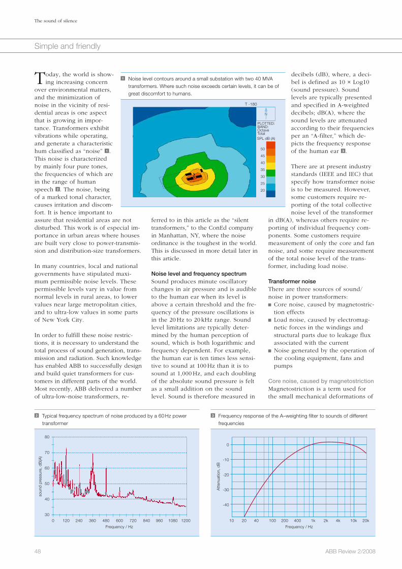
48 ABB Review 2/2008
The sound of silence
Simple and friendly
decibels (dB), where, a deci-bel is defined as 10 × Log10 (sound pressure). Sound levels are typically presented and specified in A-weighted decibels; dB(A), where the sound levels are attenuated according to their frequencies per an “A-filter,” which de-picts the frequency response of the human ear 3 .
There are at present industry standards (IEEE and IEC) that specify how transformer noise is to be measured. However, some customers require re-porting of the total collective noise level of the transformer
in dB(A), whereas others require re-porting of individual frequency com-ponents. Some customers require measurement of only the core and fan noise, and some require measurement of the total noise level of the trans-former, including load noise.
Transformer noiseThere are three sources of sound/noise in power transformers: Core noise, caused by magnetostric-tion effects
Load noise, caused by electromag-netic forces in the windings and structural parts due to leakage flux associated with the current
Noise generated by the operation of the cooling equipment, fans and pumps
Core noise, caused by magnetostrictionMagnetostriction is a term used for the small mechanical deformations of
ferred to in this article as the “silent transformers,” to the ConEd company in Manhattan, NY, where the noise ordinance is the toughest in the world. This is discussed in more detail later in this article.
Noise level and frequency spectrumSound produces minute oscillatory changes in air pressure and is audible to the human ear when its level is above a certain threshold and the fre-quency of the pressure oscillations is in the 20 Hz to 20 kHz range. Sound level limitations are typically deter-mined by the human perception of sound, which is both logarithmic and frequency dependent. For example, the human ear is ten times less sensi-tive to sound at 100 Hz than it is to sound at 1,000 Hz, and each doubling of the absolute sound pressure is felt as a small addition on the sound level. Sound is therefore measured in
Today, the world is show-ing increasing concern
over environmental matters, and the minimization of noise in the vicinity of resi-dential areas is one aspect that is growing in impor-tance. Transformers exhibit vibrations while operating, and generate a characteristic hum classified as “noise” 1 . This noise is characterized by mainly four pure tones, the frequencies of which are in the range of human speech 2 . The noise, being of a marked tonal character, causes irritation and discom-fort. It is hence important to assure that residential areas are not disturbed. This work is of especial im-portance in urban areas where houses are built very close to power-transmis-sion and distribution-size transformers. In many countries, local and national governments have stipulated maxi-mum permissible noise levels. These permissible levels vary in value from normal levels in rural areas, to lower values near large metropolitan cities, and to ultra-low values in some parts of New York City.
In order to fulfill these noise restric-tions, it is necessary to understand the total process of sound generation, trans-mission and radiation. Such knowledge has enabled ABB to successfully design and build quiet transformers for cus-tomers in different parts of the world. Most recently, ABB delivered a number of ultra-low-noise transformers, re-
1 Noise level contours around a small substation with two 40 MVA transformers. Where such noise exceeds certain levels, it can be of great discomfort to humans.
50
45
40
35
30
25
20
T -180
PLOTTED:BAND:OctaveTotalSPL dB (A)
N
2 Typical frequency spectrum of noise produced by a 60 Hz power transformer
80
70
60
50
40
300 120 240 360 480 600 720 840 960 1080 1200
Frequency / Hz
3 Frequency response of the A–weighting filter to sounds of different frequencies
0
-10
-20
-30
-40
10 20 40 100 200 400 1k 2k 4k 10k 20k
Frequency / Hz
soun
d pr
essu
re, d
B(A
)
Att
enua
tion,
dB

49ABB Review 2/2008
The sound of silence
Simple and friendly
6 3-D modeling of mechanical vibrations of a three-phase core 7 3-D modeling of sound radiation from the tank of a three-phase transformer
The TrafoStar tank is designed to avoid any unnecessary noise increase through its high radiation efficiency or tank resonance. Acoustic simula-tions, verified by scale models and full-size experiments, have provided the tools needed to avoid tank reso-nances and reduce sound radiation 7 .
Lower-noise transformers
Lower core noiseIn addition to seeking low magneto-striction, using steel with higher grades of magnetic orientation for the
Sound generated by cooling equipmentThe frequency character of fan noise is different from the sound from the core and windings. It does not have discrete tones but covers a broad frequency band with a peak at the “blade pas-sage” frequency, which is the frequen-cy at which the fan impeller blades pass some rigid disturbance in the air flow – and sometimes at twice that fre-quency. Pumps also produce noise of a broad band nature and contribute to the total noise of the transformer.
Design features Power transformers of ABB’s present design generation, designated as TrafoStar, typically have noise levels that are significantly lower than those built 20 or 30 years ago. Some of the more important contributors to achiev-ing these low levels of transformer noise are: Designing transformer cores to pro-vide a more uniform distribution of magnetic flux with a lower content of flux harmonics globally in the core and locally in the core joints. Detailed 2-D and 3-D magnetic field modeling have been used to opti-mize core designs to minimize core noise 5 .
The core is held together by a clamping structure that provides uniform pressure on the core lami-nations while local deformations are avoided. ABB is using in-house developed tools to calculate the vibrations of the core considering different modes of vibrations and mechanical resonance as well as the complex forces exciting a three-phase transformer core 6 .
core laminations in response to the application of a magnetic field. The change in dimension is independent of the direction of the flux and hence it occurs at double the supply fre-quency. However, because the mag-netostriction curve is non-linear, high-er frequency harmonics of even orders are introduced at higher flux densities 4 . Therefore, core noise has components at multiples of 100 or 120 Hz (for 50 Hz and 60 Hz trans-formers, respectively). The relative magnitudes of the noise at these dif-ferent frequency components is de-pendant on core material, core geom-etry, operating flux density, and how close the resonance frequencies of core and tank are to the exciting fre-quencies.
Load noise caused by electromagnetic forcesLoad noise is mainly generated by the interaction of the load current in the windings and the leakage flux pro-duced by this current. The main fre-quency of this sound is, therefore, twice the supply frequency; 100 Hz for 50 Hz transformers and 120 Hz for 60 Hz transformers. If the load current contains significant harmonics, eg, in rectifier transformers, the forces will contain higher frequency harmonics. These additional harmonics are a sig-nificant source of noise that must be considered when the transformer is ordered. The load current noise level is strongly dependent on the trans-former load. Reducing the current by 50 percent provides a reduction of the load current noise by 12 dB.
5 Magnetic flux distribution in a three-phase core
4 Example magnetostriction curve; relative change of core steel lamination length
during a complete cycle of alternating flux
Flux density (T)
-2.0 -1.0 0.0 1.0 2.0
2
1
0
-1
2

50 ABB Review 2/2008
The sound of silence
Simple and friendly
These levels correspond to a total noise level of about 59 dB(A) at maxi-mum overexcitation and full current. The corresponding value for the total dB(A) at 100 percent voltage and full current is in the 54 dB(A) range. In comparison, transformers of this size would typically have noise levels in the 70 dB(A) range for no-load noise alone. Low-noise transformers will have 10 dB less (again, no-load value alone). This demonstrates the extent of the ConEd noise requirements rela-tive to typical or even low-noise trans-formers.
But these were not the only challeng-es. The ConEd requirements impose other design restrictions. These are: Tight limits on weight, width, and height to permit transportation in Manhattan
Tight limits on transformer imped-ance variation across the range of the tap changer
Significant overload requirements (up to 200 percent)
Limits on temperatures of hot-spots in the windings at different loads
The designs requested by ConEd were for their standardized 65 MVA and 93 MVA network transformers.
Solutions for the ConEd transformer Designing a transformer for such ultra-
Lower cooling–system noiseNoise from cooling fans can be re-duced by selecting low-speed fans or fans with sound-absorbing elements at the inlet and outlet. Other means include special fan or blade designs with improved noise performance. In many cases, in which very strict noise requirements apply, fan noise is eliminated by designing the trans-former with more radiators instead of fans. When cooling pumps are required, pumps with low noise emis-sion are adopted.
ConEd transformer requirementsIn order to satisfy the harsh limits that the NYC Noise Ordinance has im-posed on all sources of noise in the city, ConEd’s electric equipment de-partment has revised its noise specifi-cations for new power transformers. These specifications ensure ultra-low-noise transformers in the ConEd power system. These specifications have the following very stringent requirements: 1) 15 to 20 dB lower than typical for
these sizes of transformers2) Guarantee noise levels are not
exceeded at: a) 100 percent voltage combined with 100 percent load b) Maximum over-excitation combined with 40 percent load3) Limits govern not only total noise levels but also each individual frequency component
The maximum allowable limits of the frequency spectrum of the total noise of the transformer (sum of no-load and load noise) for the three most important frequency components of the transformer noise are shown below Factbox .
core and reducing the flux density in the core, noise from the core can be reduced by a number of other mea-sures that have been developed over the years. These include: De-coupling of core vibrations from the transformer tank. In order to get good results from this, it is neces-sary to consider carefully the dy-namic properties of the transformer core and of the transformer tank. The vibration isolation elements need to be properly designed.
Avoiding both tank and core reso-nances. This necessitates accurately pre-determining values of the differ-ent core and tank resonance fre-quencies 8 .
Damping treatment of the tank. Using sound panels or enclosures covering parts of or the entire tank (for transformers that must fulfill especially low levels of noise).
A number of new techniques that attempt to reduce the transmissibili-ty of the core vibrations and hence the resulting sound radiation.
Lower load noiseWinding type, winding arrangement, current density, tank shielding / shunts, and tank design parameters have a significant effect on the magnitude of load noise. Extensive development work has resulted in the following measures for load-noise reduction: Using winding designs that generi-cally provide for lower magnitudes of leakage flux density
Avoiding winding resonance Improved tank shielding against leakage flux
Damping treatment of the tank Improved tank design having lower sound radiation properties
Sound enclosures covering the entire tank
Factbox Maximum allowable limits for the three most important frequencies
Octave band center
frequency (Hz)125 250 500
Permissible level (dB)
71 64 57
8 Modeling of mechanical resonance of a five-limb, three-phase core 9 Ultra-low noise ConEd transformer with Sound Enclosure

51ABB Review 2/2008
The sound of silence
Simple and friendly
tween 2 and 5 dB lower than the ultra-low levels specified by ConEd.
As a result of this success, ConEd awarded more of these 93 and 65 MVA transformers for delivery in 2008 and early 2009. These transformers were again designed using the latest tech-nology developed at ABB. It was therefore possible to upgrade the design of these transformers with significantly less weight of core and windings while still satisfying the ConEd requirements.
The ultra-low-noise transformer tech-nology resulting from this develop-ment is now being used in producing optimum designs for low-noise trans-formers for other customers in metro-politan areas around the world.
Ramsis Girgis
ABB Inc.
St. Louis, MO, USA
Jan Anger
ABB Inc.
Ludvika, Sweden
Donald Chu
ConEd
New York, NY, USA
For the next few years, the ABB tech-nology development team worked very hard on all of the seven noise- related technology areas discussed in this article. As a result of the progress achieved, ConEd awarded ABB the contract to produce the first ultra-low-noise 93 MVA transformers. These transformers were designed using the technology available at that point in time and it was successfully tested and delivered in 2005. The first of these was equipped with a sound enclosure 9 . The second and third transformers had only sound panels attached to the tank walls 10 .
The more accurately calculations can be performed, the lower the margin of the resulting design and the more fea-sible it becomes to satisfy tough specifications. After the delivery of these transform-ers, ConEd awarded ABB an order for ultra-low-noise 65 MVA transformers. These transformers were designed using the latest noise technology that was available at the time (2005). The transformers were produced with no external sound enclosure or panels 11 . In fact, the second unit was designed with significantly less winding weight while testing 4 dB lower load noise than the first unit. Frequency compo-nents of the total of core and load noise of this transformer were be-
low noise levels while at the same time satisfying all the other limitations is only possible if the transformer manu-facturer is capable of the following: Accurate calculation of the noise level of the core versus its flux den-sity
Accurate calculation of load noise Accurate calculation of resonance frequencies for the core, windings, tank plates and tank stiffeners
Accurate calculation of frequency spectrum of core noise versus flux density
Effective means of reducing both core and load noise for the different frequencies
Proper transformer mounting tech-niques
Accurate indoor measuring tech-niques of low noise levels in the factory
The more accurately calculations can be performed, the lower the margin of the resulting design and the more feasible it becomes to satisfy tough specifications.
A success storyAs of the spring of 2003, ABB had the technology to design low-noise trans-formers but not to the levels or the details required by the revised specifi-cations for the ConEd ultra-low-noise transformers. Recognizing this fact, ABB identified the research and devel-opment work that needed to be done to advance the technology existing at the time to the level of rigor necessary to successfully design and build the transformers required by ConEd.
10 Ultra-low noise ConEd transformer with Sound Panels 11 Ultra-low noise ConEd transformer with no Sound Enclosure or Panels

52 ABB Review 2/2008
Simple and friendly
Light, safe and effectiveHVDC Light® cable systems are the future of power transmissionAnders Gustafsson, Marc Jeroense, Johan Karlstrand
As the global population continues to grow, resources are becoming ever more stretched. Growing populations need more land as well as adequate electrical, water and com-munication services, and these must be provided in a way that complies with the now compulsory environmental reg-ulations. For its part, the energy sector has been working hard to find safe and innovative ways of increasing power transmission in power corridors while keeping the environ-mental impact to a minimum.
One company particularly active in this area is ABB. Over the past number of years, the company has developed transmission capabilities that not only bring more power to the people, but it does so in a safe and invisible way. Using HVDC Light® cable, transmission systems are more com-pact, effective, require low maintenance and are environ-mentally friendly.
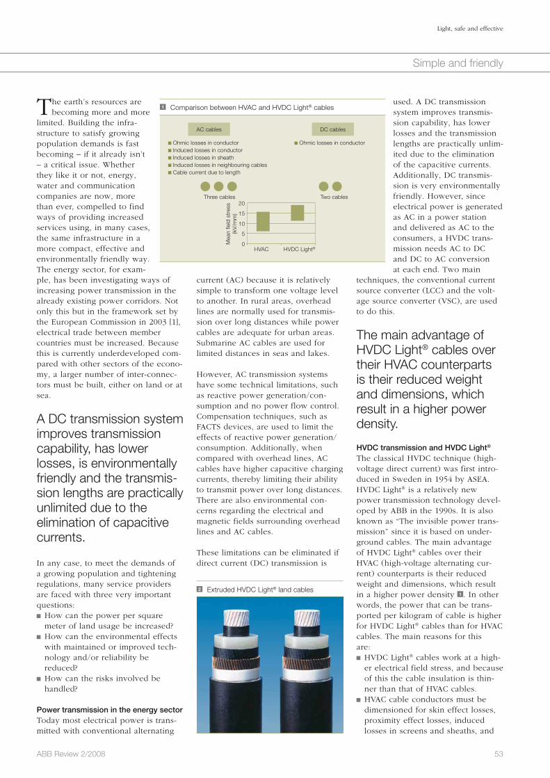
53ABB Review 2/2008
Light, safe and effective
Simple and friendly
used. A DC transmission system improves transmis-sion capability, has lower losses and the transmission lengths are practically unlim-ited due to the elimination of the capacitive currents. Additionally, DC transmis-sion is very environmentally friendly. However, since electrical power is generated as AC in a power station and delivered as AC to the consumers, a HVDC trans-mission needs AC to DC and DC to AC conversion at each end. Two main
techniques, the conventional current source converter (LCC) and the volt-age source converter (VSC), are used to do this.
The main advantage of HVDC Light® cables over their HVAC counterparts is their reduced weight and dimensions, which result in a higher power density.
HVDC transmission and HVDC Light®
The classical HVDC technique (high-voltage direct current) was first intro-duced in Sweden in 1954 by ASEA. HVDC Light® is a relatively new power transmission technology devel-oped by ABB in the 1990s. It is also known as “The invisible power trans-mission” since it is based on under-ground cables. The main advantage of HVDC Light® cables over their HVAC (high-voltage alternating cur-rent) counterparts is their reduced weight and dimensions, which result in a higher power density 1 . In other words, the power that can be trans-ported per kilo gram of cable is higher for HVDC Light® cables than for HVAC cables. The main reasons for this are: HVDC Light® cables work at a high-er electrical field stress, and because of this the cable insulation is thin-ner than that of HVAC cables.
HVAC cable conductors must be dimensioned for skin effect losses, proximity effect losses, induced losses in screens and sheaths, and
current (AC) because it is relatively simple to transform one voltage level to another. In rural areas, overhead lines are normally used for transmis-sion over long distances while power cables are adequate for urban areas. Submarine AC cables are used for limited distances in seas and lakes.
However, AC transmission systems have some technical limitations, such as reactive power generation/con-sumption and no power flow control. Compensation techniques, such as FACTS devices, are used to limit the effects of reactive power generation/consumption. Additionally, when compared with overhead lines, AC cables have higher capacitive charging currents, thereby limiting their ability to transmit power over long distances. There are also environmental con-cerns regarding the electrical and magnetic fields surrounding overhead lines and AC cables.
These limitations can be eliminated if direct current (DC) transmission is
The earth’s resources are becoming more and more
limited. Building the infra-structure to satisfy growing population demands is fast becoming – if it already isn’t – a critical issue. Whether they like it or not, energy, water and communication companies are now, more than ever, compelled to find ways of providing increased services using, in many cases, the same infrastructure in a more compact, effective and environmentally friendly way. The energy sector, for exam-ple, has been investigating ways of increasing power transmission in the already existing power corridors. Not only this but in the framework set by the European Commission in 2003 [1], electrical trade between member countries must be increased. Because this is currently underdeveloped com-pared with other sectors of the econo-my, a larger number of inter-connec-tors must be built, either on land or at sea.
A DC transmission system improves transmission capability, has lower losses, is environmentally friendly and the transmis-sion lengths are practically unlimited due to the elimination of capacitive currents.
In any case, to meet the demands of a growing population and tightening regulations, many service providers are faced with three very important questions: How can the power per square meter of land usage be increased?
How can the environmental effects with maintained or improved tech-nology and/or reliability be reduced?
How can the risks involved be handled?
Power transmission in the energy sectorToday most electrical power is trans-mitted with conventional alternating
1 Comparison between HVAC and HVDC Light® cables
Three cables
Mea
n fie
ld s
tres
s (k
V/m
m)
HVAC
20
15
10
5
0HVDC Light®
Two cables
Ohmic losses in conductor Induced losses in conductor Induced losses in sheath Induced losses in neighbouring cables Cable current due to length
Ohmic losses in conductor
AC cables DC cables
2 Extruded HVDC Light® land cables

54 ABB Review 2/2008
Light, safe and effective
Simple and friendly
been installed, with another 400 km on the way proving that HVDC Light® really is a mature and reliable technol-ogy. On top of this, approximately 500 cable joints are now in service. This can be compared to the more than 1,700 km of mass impregnated cables installed by ABB since 1953.
InstallationThe relatively low weight, small di-mensions – which enable a reduced number of joints – and robustness of HVDC Light® cables have a positive influence on installation costs, which constitute a significant part of the total investment cost. This, combined with newly developed land installation equipment, means that the cost ratios between overhead line systems and those based on HVDC polymer cables are – depending on the circuit length and conditions – comparatively low.
Nowadays, installation is aided by mechanized cable laying machines with wheel cutters and automated backfilling devices. Existing infrastruc-tures often have defined soil composi-tions and installation is easier if boul-ders etc. can be avoided. In one proj-ect in Australia, HVDC Light® cables 3 were laid at a speed of one to three kilometers per day [6, 7]. This is pos-sible only with HVDC Light® technolo-gy and lean HVAC XLPE cable de-signs.
HVDC Light® cables can be installed on land or at sea. Their relatively low weight and dimensions strongly influ-ence the amount of cable that can be reeled up on one drum, or the amount that can be transported on a cable installation vessel.
Environmental effectsBesides the economical benefits of using less land for transmission sys-tems in existing infrastructures, the environmental impact of using HVDC Light® is also reduced. For example,
Overall, a robust HVDC Light® system is deemed a low maintenance and cost-effective solution.
More power on less landA comparison between HVAC XLPE Cables, HVDC Light® cables and over-head lines for systems typically rated between 220 kV and 400 kV is shown in the Factbox . The width of the right of way (ROW) or affected width of the land is given in the same table.
In terms of power transmission, it can be seen from the table that a HVDC Light® system is approximately 25 to 30 times more compact than the cor-responding overhead line system. If the power rating per kg of the two is also compared, then a HVDC cable system is about 15 to 25 times more effective.
In terms of power trans-mission, the HVDC Light® system is approximately 25 to 30 times more compact than the corresponding overhead line system.
ReliabilityThe first commercial HVDC Light® cable system was installed in Sweden in 1999. A wind park at the southern tip of Gotland island was connected to the city of Visby, also located on Gotland, by an 80 kV, 50 MW connec-tion. Since then many other projects have been realized, including the Estlink project, a 150 kV, 350 MW link [3]. In less than a decade, almost 1,500 km of HVDC Light® cables have
in the case of submarine cables, in-duced losses in armouring. HVDC Light® cables have to be dimen-sioned only for their ohmic conduc-tor losses.
An HVAC cable system needs three cables whereas a HVDC cable sys-tem only needs two.
Polymer HVDC Light® cable systems 2 have been developed, installed and are in service on voltage levels from 80 kV to 150 kV. These installed sys-tems cover power ranges from 50 MW [2] to 350 MW [3].
It is foreseen that the future demand for HVDC transmission and in particu-lar HVDC cables will increase. The fact that long electrical power trans-mission can be built underground makes ABB’s HVDC Light® system very attractive. Currently, the tradi-tional market and technical driving force behind the use of HVDC cable systems is long distance submarine transmission, which is necessary espe-cially if asynchronous networks need to be connected together1). But the in-troduction of VSC and extruded poly-mer HVDC cables has created new market potential for HVDC Light® sys-tems. For example, remote locations with weak networks can now be easi-ly connected to, as can off-shore wind power2) [4], and oil and gas platforms [5]. “Undergrounding” has been identi-fied as a strong market driver. The forces behind this include new and demanding European EMF standards, more difficult and time consuming “permission processes” for overhead lines (in particular in Europe), and in-creasing public opinion that solutions with higher aesthetic values are need-ed.
Factbox Comparing different cable transmission systems
HVAC XLPE Cables
HVDC Light® Cables
Overheadline
220 kV rating 200–500 MVA100–300 MVA
(150 kV)300–800 MVA
400 kV rating 400–1,000 MVA300–1,000 MVA
(320 kV)500–2,000 MVA
Width of affected land
1–2 m 0.5–1 m 40–60 m
MVA/m for 220–420 kV
200–500 MVA/m 200–1,000 MVA/m 7.5–33 MVA/m
Footnotes1) Traditionally paper insulated cables are used for
these kinds of connections.2) One of the characteristics of HVDC Light® is its
superior ability to stabilize the AC voltage at the
terminals. This is particularly important for wind
parks, where the variation in wind speed can cause
severe voltage fluctuations.

55ABB Review 2/2008
Light, safe and effective
Simple and friendly
to transfer electricity over long dis-tances mean a more comfortable elec-trical transmission system is easier to obtain.
Anders Gustafsson
Marc Jeroense
Johan Karlstrand
ABB Power Systems
Karlskrona, Sweden
reduce the short-circuit current to zero approximately 15–20 times faster than conventional AC lines and this will have a positive effect on the personal risks involved.
Non-invisible benefitsThe use of extruded HVDC Light® ca-bles for electrical transmission has several advantages. The most obvious is that cables that are laid under-ground make the electrical energy transport invisible. This together with the other advantages of using DC ca-bles, such as environmental and safety related features as well as the ability
an overhead line system routed through a forest results in a loss of CO
2 uptake because trees convert car-
bon dioxide from the atmosphere into carbon stored in the wood. In fact, a 400 kV line through a forest repre-sents a loss of approximately 42 tons of CO
2 per km per year [7].
The earth’s magnetic field originates from large convective DC currents in its interior. This natural magnetic field varies from between 30 to 60 µTesla for different latitudes on the earth’s surface. The same type of magnetic field is produced by an HVDC Light® cable, and is not considered unhealthy to the human body. A DC cable will generate a magnetic field of between 5 and 10 µTesla one meter above the ground surface. This will then be su-perposed to the natural magnetic field of the earth, which is much the same as saying that the magnetic effect from a DC cable corresponds to travelling from the south to the north of the earth. This is not considered danger-ous from a magnetic point of view. With regard to an AC field, a discus-sion has been ongoing and some pre-caution limits have been established in some countries, but as of yet, no definite conclusions have been reached.
In less than a decade, almost 1,500 km of HVDC Light® cables have been installed, with another 400 km on the way. SafetyThe laying and installing of cables along roads or other infrastructures is generally easier than in the country-side. Cable positions and locations can be defined according to the sys-tems used to route roads or railways. National road and railway administra-tions normally have very good sys-tems for doing this. In Sweden all roads have fixed coordinates in a GPS system, which means that other ser-vices like electrical and fiber cables can be positioned and logged in the same system. Hence, the risk for third-party damage is reduced. Addi-tionally, an HVDC Light® system will
3 Laying HVDC Light® cable in Australia: Transporting the large cable drums a . Preparing to lay the cable using a chain excavator (left) and refilling machine (right) b . A typical narrow cable trench with minimum environmental intrusion c .
References
[1] Regulation (EC) No 1228/2003 – on conditions for access to the network for cross-border exchanges in
electricity, 26 June 2003.
[2] Green, S. (July 2004). HVDC Systems Gotland: the HVDC pioneer. Power Engineering International.
[3] Pajo, R., Aarna, I., Lahtinen, M. (April 2007). Estlink tie Improves Baltic States system. Transmission and
Distribution World.
[4] E.ON lässt Offshore-Windpark für 300 Millionen Euro ans Netz anschliessen. Energie-Chronik, September
2007. http://www.udo-leuschner.de/energie-chronik/070910.htm
[5] Jones, P., Stenius, L. (2006). The Challenges of Offshore Power System Construction – Troll A, Electrical
Power delivered successfully to an oil and gas platform in the North Sea. EWEC, Athens.
[6] Mattsson, I. et al. (2004). Murray Link – the longest underground HVDC cable in the world. CIGRE paper
B4-103.
[7] Ravemark D., Normark B. Light and invisible. ABB Review 4/2005, 25–29.
Further reading
Flisberg G., Englund L., Kumar A. (2005). HVDC transmits green energy in China. ABB Review Special Report
ABB in China, 15–18.
a c
b

56 ABB Review 2/2008
Thema
Success story Looking back at ABB’s contribution to industrial roboticsDavid Marshall, Christina Bredin
Industrial robots are omnipresent in discrete manufacturing across the world: increasing productivity, providing consis-tent high quality and improving workplace safety. The ad-vancements made during the last 35 years have been sig-nificant. Initially, single robots were used for relatively sim-
ple and monotonous tasks in hazardous environments. Today, multi-robot synchronized systems are dealing with sophisticated assignments in flexible produc-
tion cells. ABB has been a prime driver in this rapid development process.
PERPETUAL PIONEERING

57ABB Review 2/2008
Success story
Initially, this automatic painter was used solely internally but such was its success that Trallfa decided to market it outside the company. Its first sale of the Trallfa TR 2000 was in 1969 to the Swedish company Gustavsberg for enameling standard bathroom installations such as bathtubs and shower trays.
In 1985, Trallfa was acquired by ASEA, and in 1988 – the year ASEA merged with the Swiss company Brown Boveri to form ABB – the com-pany released its first electric drive painting robot, the TR 5000. Prior to this development, hydraulic drives were exclusively used for painting robots due to their intrinsic safety. The TR 5000, however, saw such safe-ty achieved with electric drives, and their inherent benefits of speed, accu-racy and electronic controls were brought to the painting process.
60 kg capacity. The first of these was supplied to Saab in Sweden for spot welding car bodies 2 . Perhaps the “final nail in the coffin” of the hydrau-lic robot spot welder was the IRB 90, launched in 1982, which ASEA de-signed specifically for spot welding. It was a full six-axis device with inte-grated water, air and current (WAC) supplies built into the arm.
In the 1990s, ABB re-leased its innovative Car-tridge Bell System (CBS) for painting car parts, which is now being ap-plied on automotive pro-duction lines worldwide.
Robots for paintingStill in the era of the hydraulic robot, a significant event took place in Nor-way, which later impacted ASEA’s ro-bot business. Trallfa, a small agricul-tural engineering company, was hav-ing difficulty in recruiting labor to paint its wheelbarrows and sought a solution through automation – a chal-lenge taken up by a young engineer, Ole Molaug. In 1966, he developed the world’s first painting robot driven by hydraulics 3 . It differed from the Unimate in that it had continuous path control and programs were creat-ed by recording the spray patterns of a skilled painter onto magnetic tape.
The first industrial robot appeared in 1961 when a Unimate was sup-
plied to General Motors for tending a die-casting machine. The Unimate – the brainchild of Joseph Engelberger, the “Father of the Industrial Robot” – was hydraulically driven, a technology that dominated the fledgling industrial robot business for its first decade. Then, in 1974, the Swedish company ASEA developed the IRB 6, the first all-electric industrial robot. This 6 kg capacity device was unique, not only in the drive system but also in its an-thropomorphic configuration and its use of a microprocessor control sys-tem. It set new robot standards in the small footprint, the speed of move-ment and positioning accuracy, and gave rise to a number of IRB 6 look-alikes.
Electric-drive robots opened up new applications not possible with hydrau-lic machines, in particular arc weld-ing. The first application outside of ASEA was the polishing of stainless steel pipe bends for the food industry at the Swedish company Magnusson. Its first IRB 6 was installed in 1974 1 , with further units delivered in 1975 – these were robots that ran virtually nonstop in a dirty environment for over 25 years.
Spot welding continued to be the do-main of the hydraulic robot until 1975, when ASEA launched the IRB 60, simi-lar in design to the IRB 6 but with a
1 In 1974, Magnusson AB became ASEA’s first external robot customer. Manager Leif Jönsson together with Lennart Benz of ASEA monitor the installation.
2 The SAAB Model 99 of 1975 was an early spot-welding application.
Photo courtesy of SAAB
PERPETUAL PIONEERING
3 Early version of the Trallfa paint robot from 1969
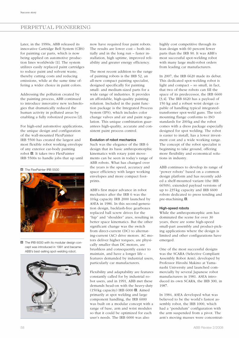
58 ABB Review 2/2008
Success story
highly cost competitive through its lean design with 60 percent fewer parts than the IRB 90. It was ABB’s most successful spot-welding robot with many large multi-robot orders from leading car manufacturers.
In 2007, the IRB 6620 made its debut. This dedicated spot-welding robot is light and compact – so small, in fact, that two of these robots can fill the space of its predecessor, the IRB 6600 [3,4]. The IRB 6620 has a payload of 150 kg and a robust wrist design ca-pable of handling typical integrated-transformer spot-weld guns. The tool-mounting flange conforms to ISO standards for 200 kg and the robot comes with a dress package especially designed for spot welding. The robot is easier to install, has a lower invest-ment cost and a wide working range. The concept of the robot specialist is beginning to take ground, offering more flexibility and economical solu-tions in industry.
ABB continues to develop its range of “power robots” based on a common design platform and has recently add-ed a shelf-mounted variant (the IRB 6650S), extended payload versions of up to 235 kg capacity and IRB 6600 robots dedicated to press tending and pre-machining 6 .
High-speed robotsWhile the anthropomorphic arm has dominated the scene for over 30 years, there are some high-speed small-part assembly and product-pick-ing applications where the design is limited and other configurations have emerged.
One of the most successful designs was the SCARA (Selective Compliant Assembly Robot Arm), developed by Professor Hiroshi Makino at Yama-nashi University and launched com-mercially by several Japanese robot manufacturers in 1981. ASEA intro-duced its own SCARA, the IRB 300, in 1987.
In 1984, ASEA developed what was believed to be the world’s fastest as-sembly robot, the IRB 1000, which had a “pendulum” configuration with the arm suspended from a pivot. The arm’s moving masses were concentrat-
now have required four paint robots. The results are lower cost – both ini-tially and in the long run – faster in-stallation, high uptime, improved reli-ability and greater energy efficiency.
The most recent addition to the range of painting robots is the IRB 52, an all-new compact painting specialist, designed specifically for painting small- and medium-sized parts for a wide range of industries. It provides an affordable, high-quality painting solution. Included in the paint func-tion package is the Integrated Process System (IPS), which includes color change valves and air and paint regu-lation. This unique combination guar-antees high-quality, accurate and con-sistent paint process control.
Evolution of robot mechanicsSuch was the elegance of the IRB 6 design that its basic anthropomorphic kinematics with rotary joint move-ments can be seen in today’s range of ABB robots. What has changed over the years is the speed, accuracy and space efficiency with larger working envelopes and more compact foot-prints.
ABB’s first major advance in robot mechanics after the IRB 6 was the 10 kg capacity IRB 2000 launched by ASEA in 1986. In this second-genera-tion design, backlash-free gearboxes replaced ball screw drives for the “hip” and “shoulder” axes, resulting in better space kinematics. But the other significant change was the switch from direct-current (DC) to alternat-ing-current (AC) drive motors. AC mo-tors deliver higher torques, are physi-cally smaller than DC motors, are brushless and consequently easier to maintain, and have a longer life – features demanded by industrial users, particularly car manufacturers.
Flexibility and adaptability are features constantly called for by industrial ro-bot users, and in 1991, ABB met these demands head-on with the heavy-duty (150 kg capacity) IRB 6000 5 . Aimed primarily at spot welding and large component handling, the IRB 6000 was built on a modular concept with a range of base, arm and wrist modules so that it could be optimized for each user’s needs. The IRB 6000 was also
Later, in the 1990s, ABB released its innovative Cartridge Bell System (CBS) for painting car parts, which is now being applied on automotive produc-tion lines worldwide [1]. The system utilizes easily replaced paint cartridges to reduce paint and solvent waste, thereby cutting costs and reducing emissions, while at the same time of-fering a wider choice in paint colors.
Addressing the pollution created by the painting process, ABB continued to introduce innovative new technolo-gies that dramatically reduced the human activity in polluted areas by enabling a fully robotized process [2].
For high-end automotive applications, the unique design and configuration of the wall-mounted FlexPainter IRB 5500 has created the largest and most flexible robot working envelope of any exterior car-body painting robot 4 . It takes two FlexPainter IRB 5500s to handle jobs that up until
4 The FlexPainter IRB 5500
5 The IRB 6000 with its modular design con-cept was introduced in 1991 and became ABB’s best-selling spot-welding robot.
PERPETUAL PIONEERING

59ABB Review 2/2008
Success story
Dynamic modelingThe concept employed by ABB to im-prove robot performance with the S4 was “motion control,” using smart software functions rather than purely increasing mechanical performance. The foundation of this motion control is a complete dynamic model of the robot held in the S4 and is the basis of QuickMove, a function in which the maximum acceleration in any move is determined and used on at least one axis so that the end position is reached in the shortest time. As a result, cycle time is minimized and is not dependent purely on axis speeds.
Another feature emanating from dy-namic modeling is minimal deviation from the programmed path, which is applied in TrueMove. This function ensures the motion path followed is the same whatever the speed and ob-viates the need for “path tuning” when speed parameters are adjusted online.
center point (TCP) and a new pro-gramming language, ARLA (ASEA ro-bot programming language). These features enabled easier and quicker programming and setup for both ex-perienced and untrained robot users.
Other new software for the S2 includ-ed limited process software such as arc-welding functions and built-in weld timers for spot welding, and a kinematics model of the robot arm. The latter exploited in the IRB 6000 enabled the robot to gain a level of performance not limited by the physi-cal stiffness of the physical structure, and was ABB’s first step along the road to the complete dynamic and kinematics modeling available in today’s products.
A dramatic advance in robot control was the IRC 5 control system, which could simultane-ously control up to 36 axes through a new function, MultiMove.
The S3 control unit introduced in 1986 differed from the S2 mainly in its switch to AC drives, such as for the IRB 2000 series. The next big change came with the S4, launched in 1992 and which many at ABB regarded as big an advance as the introduction of the IRB 6 and S1. Over 150 man-years went into developing the multi-micro-processor S4, which could control six external axes, all welding parameters as well as the robot’s own six axes.
The S4 controller was designed to im-prove two areas of critical importance to the user: the man-machine interface and the robot’s technical performance. A vital key to the former was the Win-dows-style teach pendant. It was the same familiar environment as used in PCs with dropdown menus and dia-logue boxes, so that setup and opera-tion of the robot was simplified. At the same time, programming was made easier through a new, open multi-level programming language, RAPID, with the flexibility to develop or adapt functions to meet each user’s specific needs.
ed at the pivot, minimizing the mo-ments of inertia and resulting in accel-erations of 2G within a working enve-lope much larger than possible with a SCARA.
But even these robots were not fast enough for online picking operations in such as the electronics and food in-dustries. To meet this demand, ABB introduced the IRB 340 FlexPicker robot in 1998. Based on the Delta ro-bot conceived by Professor Raymond Clavel at Ecole Polytechnique Fédérale de Lausanne (EPFL) in Switzerland, the FlexPicker is capable of 10G accelera-tion and 150 picks-per-minute cycle times, matching human operators in both speed and versatility when han-dling small items, such as electronic components and chocolates 7 .
The development of the FlexPicker has been a key research and develop-ment focus, and in 2008, ABB will in-troduce the world’s first second-gener-ation high-speed picking robot, the IRB 360. The new robot features a higher payload and smaller footprint, and when combined with PickMaster software and the IRC 5 robot control-ler, this new robot system will further improve productivity and flexibility in packing operations.
Advances in control systemsWhile mainstream robot kinematics has continued on an evolutionary path, the control systems, operator in-terfaces – including human-machine interfaces (HMIs) – and software have changed beyond recognition. The control system for the IRB 6 devel-oped in 1974, later designated the S1 and very advanced for its time, had just a single 8 bit Intel 8008 micropro-cessor, an HMI with a four-digit LED readout and 12 punch buttons, and rudimentary software for axis interpo-lation and movement control. The ro-bot required specialist knowledge to program and operate.
The first breakthrough in setup and programming came with the S2 intro-duced in 1981. Based on two Motoro-la 68000 microprocessors, the S2’s HMI or “teach pendant” incorporated a joystick for intuitive jogging and po-sitioning of the robot axes. Also intro-duced were the concept of the tool
6 Holding a spot-welding gun
PERPETUAL PIONEERING
7 The FlexPicker in action

60 ABB Review 2/2008
Success story
offers functions such as electronic position switches, programmable safe zones, safe speed limits, safe standstill positions and an automatic brake test, which allows more flexible safety set-ups. The result: Robots and humans can collaborate and work safely and efficiently side by side.
In 2008, ABB will intro-duce the world’s first second-generation high-speed picking robot, the IRB 360.
Coordinated multi-robot controlA further dramatic advance in robot control was made by ABB in 2004 when it launched the fifth-generation IRC 5 control system. An outstanding feature of IRC 5 is its ability to simul-taneously control up to four ABB ro-bots plus work positioners or other servo devices – a total of 36 axes – in fully coordinated operation through a new function, MultiMove.
Controlling up to four robots from a single controller minimizes installation costs and brings quality and produc-tivity benefits. It also opens up com-pletely new application possibilities: Two arc-welding robots can work in tandem on the same workpiece and deliver even heat input and eliminate distortion due to shrinkage on cool-ing; several robots can in concert han-dle a single flimsy workpiece to pre-vent bending; and two or more robots can lift a load larger than the capacity of the one robot.
In seeking a lean solution for robot control, ABB developed a modular
tor simply moves the robot by hand to teach it the rough path. The robot automatically follows the part, record-ing the exact path and generating a robot program. The application com-prises advanced sensor signal process-ing, mathematics, logic solution and a graphical user interface for quick, in-tuitive and accurate hands-on pro-gramming.
This innovative approach not only im-proves the quality of the finished parts, but it also reduces overall pro-gramming time by up to 80 percent, reduces the cycle time of the robot by 20 percent and extends the lifetime of the grinding tools by 20 percent.
Next generation robot safetyTo ensure the safety of people work-ing with industrial robots, humans and robots were traditionally separated by fences, and expensive safety equip-ment was necessary [6]. In 2007, ABB made it possible to replace this costly safeguarding equipment with SafeMo-ve, which features independent, com-pact, efficient and reconfigurable elec-tronic motion safety technology.
SafeMove is an independent computer housed in the cabinet of ABB’s fifth-generation industrial robot controller, the IRC 5, and allows the reliable, fault-tolerant monitoring of robot speed and position, and the detection of any unwanted or suspicious devia-tion from the norm. If a safety hazard is detected, SafeMove executes an emergency stop, halting the robot within fractions of a second. SafeMove
But once again ABB has not rested on its laurels and has continued to devel-op and improve its motion control technologies. ABB robot users can now benefit from even faster cycle times and greater precision with the introduction of ABB’s next generation of motion control technology. The second-generation versions of ABB’s QuickMove and TrueMove technology help users achieve up to 50 percent better path performance and a 20 per-cent reduction in cycle times without compromising quality. Featuring en-hanced control algorithms, Quick-Move and TrueMove offer even great-er accuracy at high speeds. ABB ro-bots can now outpace competitor cycle times by as much as 30 percent.
FlexFinishing and Force Control Another recent leap forward in robot applications is ABB’s development of a FlexFinishing system featuring Ro-botWare Machining FC (force control) for delicate operations – specifically, for grinding, deburring and polishing castings [5]. The unique robot applica-tion, launched in 2007, combines five innovative elements: Use of the latest ABB robot control-ler, IRC 5, with its high-speed sen-sor interface
A programming environment that al-lows the robot to find the optimum path itself
A feedback loop to control the pres-sure of the tool
A feedback loop to adjust the speed of the tool
An easy-to-use, pre-engineered product offer
The application allows simple and efficient programming by using the force sensor to define the trajectory for the robot movement – the opera-
PERPETUAL PIONEERING
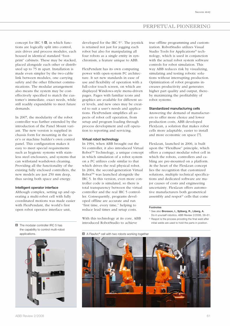
61ABB Review 2/2008
Success story
true offline programming and custom-ization. RobotStudio utilizes Visual Studio Tools for Applications® tech-nology, which is used in conjunction with the actual robot system software controls for robot simulation. This way ABB reduces risk by visualizing, simulating and testing robotic solu-tions without interrupting production. Optimization of robot programs in-creases productivity and generates higher part quality and output, there-by maximizing the profitability of robot systems.
Standardized manufacturing cellsAnswering the demand of manufactur-ers to offer more choice and lower production costs, ABB developed FlexLean, a solution that makes robot cells more adaptable, easier to install and more economic on space [7].
FlexLean, launched in 2006, is built upon the “FlexiBase” principle, which offers a compact modular robot cell in which the robots, controllers and ca-bling are pre-mounted on a platform. At the heart of the FlexLean concept lies the recognition that customized solutions, multiple technical specifica-tions and dedicated software are ma-jor causes of costs and engineering uncertainty. FlexLean offers automo-tive manufacturers both geometrical assembly and respot2) cells that come
developed for the IRC 51). The joystick is retained not just for jogging each robot but also for manipulating all four robots as a single entity in syn-chronism, a feature unique to ABB.
FlexPendant has its own computing power with open-system PC architec-ture. It set new standards in ease of use and flexibility of operation with a full-color touch screen, on which are displayed Windows-style menu-driven pages. Pages with familiar icons and graphics are available for different us-er levels, and new ones may be creat-ed to suit a user’s needs and applica-tions. FlexPendant simplifies all as-pects of robot cell operation, from setup and program loading through process development and cell opera-tion to reporting and servicing.
Virtual robot technologyIn 1994, when ABB brought out the S4 controller, it also introduced Virtual RobotTM Technology, a unique concept in which simulation of a robot system on a PC utilizes code similar to that which drives the real physical robot. In 2004, the second-generation Virtual RobotTM was launched alongside the IRC 5. In this version, even more con-troller code is simulated, so there is total transparency between the virtual controller and the real IRC 5 control-ler. Consequently, programs devel-oped offline are accurate and run “first time, every time,” helping to reduce lead times and setup costs.
With this technology at its core, ABB introduced RobotStudio to achieve
concept for IRC 5 8 , in which func-tions are logically split into control, axis drives and process modules, each housed in identical standard “foot-print” cabinets. These may be stacked, placed alongside each other or distrib-uted up to 75 m apart. Installation is made even simpler by the two-cable link between modules, one carrying safety and the other Ethernet commu-nications. The modular arrangement also means the system may be cost-effectively specified to match the cus-tomer’s immediate, exact needs, while still readily expandable to meet future demands. In 2007, the modularity of the robot controller was further extended by the introduction of the Panel Mount vari-ant. The new version is supplied in chassis form for mounting in the us-er’s or machine builder’s own control panel. This configuration makes it easy to meet special requirements such as hygienic systems with stain-less steel enclosures, and systems that can withstand washdown cleaning. Providing all the functionality of the existing fully enclosed controllers, the new models are just 250 mm deep, thus saving both space and energy.
Intelligent operator interfaceAlthough complex, setting up and op-erating a multi-robot cell with fully coordinated motions was made easier with FlexPendant, the world’s first open robot operator interface unit,
8 The modular controller IRC 5 has the capability to control multi-robot applications. 9 A FlexArc® cell with two robots working together
Footnotes1) See also Brorsson, I., Sjöberg, R., Liberg, A.
Do-it-yourself robotics. ABB Review 2/2006, 58–61.2) Respot is the process providing the final weld after
initial welds are used to hold the parts in position.
PERPETUAL PIONEERING

62 ABB Review 2/2008
Success story
hensive range of industrial robots, robot controllers and associated software. In the inter vening 30-some years, positioning accuracies have improved from 1 mm to 10 microns, user interfaces from a 4-digit LED readout to a full Windows touch-screen display and computing power from 8 kb to 20 GB or more. At the same time, reliability has increased to 80,000 hours MTBF (mean time between failures) and costs have plum-meted so that today, the robot price is half in actual terms than it was just 15 years ago. The world of the industrial robot is well past its early dawn.
This article has been adapted from
“Thirty years in robotics,” ABB Review
Special Report Robotics (2005).
David Marshall
ABB Robotics
Milton Keynes, UK
Christina Bredin
ABB Robotics
Västerås, Sweden
References
[1] Yoshida, O. More colors, less waste. ABB Review
1/2006, 43–46.
[2] Labourdette, H. More productivity, less pollution.
ABB Review 2/2007, 58–61.
[3] Svanström, O. Robotic specialists. ABB Review
3/2007, 65–67.
[4] Dunberg, K. Welding dedication. ABB Review
3/2007, 63–64.
[5] Fixell, P., Groth, T., Isaksson, M., et al. A touch-
ing movement. ABB Review 4/2007, 22–25.
[6] Kock, S., Bredahl, J., Eriksson, P. J., et al.
Taming the robot. ABB Review 4/2006, 11–14.
[7] Negre, B., Legeleux, F. FlexLean. ABB Review
4/2006, 6-10.
[8] Blanc, D., Schroeder, J. Wellness for your profit
line. ABB Review 4/2007, 42–44.
The technology is embedded in the robot controller and reads the internal data, sending it directly to a remote service center, where the data is auto-matically analyzed. By accessing all relevant information on the robot con-ditions, the support expert can re-motely identify the cause of a failure and provide fast support to the end user to restart the system. Many issues can hence be solved without travel-ing, thereby saving energy and reduc-ing emissions. Where field interven-tion is necessary, the resolution at the site is rapid and minimal, supported by the remote diagnostics system. The automatic analysis not only gives an alert when a failure with the robot oc-curs, but also predicts a difficulty that may present itself in the future. At any time and from anywhere, a user can verify robot status and access impor-tant maintenance information about that robot system by logging into ABB’s MyRobot Web page.
Since ASEA presented the first all-electric microprocessor-controlled robot in 1974, industrial robotics has advanced beyond all recognition. ABB has continued its pioneering develop-ments, culminating in today’s compre-
with a choice of pre-defined configurations and a broad range of robotic products. This robot technology and standardization results in cells that can produce so cost-efficiently that they can compete with manual labor in low-cost countries.
Another addition to the range of standardized cells is FlexArc® – a complete arc-welding package 9 . It in-cludes all the components necessary for robotic arc welding: robots, the IRC 5 robot control system sup-porting the coordination of multiple robots, positioners, and welding equipment. Customers can choose be-tween several single- or multi-robot production solu-tions. All internal cables have been routed and con-nected in the factory. Again, all cell components are mounted on a common base, eliminating the need for on-site engineering work. Software has been pre-configured for simple setup and operation. The customer must simply unwrap the package, place the cell in the desired location, connect the pow-er cable, air pressure and shielding gas, program the robot (or download a program from RobotStudio, ABB’s offline programming system) and start production. As a packaged solution, a FlexArc® cell can be moved within or between different production facili-ties. This allows engineers to design highly flexible plant layouts that meet today’s demands for rapid change-overs.
Remote serviceWith ABB’s installed base of more than 160,000 robots, reduced perfor-mance or problems with the robots can significantly impact production [8]. When a service engineer has to travel to the robot’s site to assess the problem, time and money are lost. But with ABB’s remote service technologies, developed in 2007, equipment downtime and on-site maintenance efforts are significantly reduced.
PERPETUAL PIONEERING

63ABB Review 2/2008
Preview 3/2008
Power electronics
From tiny electronic cameras to pow-erful heaters, most electrical devices in our homes have an inscription somewhere that specifies their desired electrical supply in volts and hertz. Usually, however, users take the char-ger or cable that came with the prod-uct and trust that this is securing the appropriate supply. It is maybe only when they seek a second charger for a phone or laptop that such details are verified. Just as these everyday d evices need the right power supply to function optimally, so do electrical installations in all branches of industry and across the transmission and distri-bution networks.
Electricity is supplied and used at a broad range of different voltages and frequencies, with different combina-tions of these parameters being suited to different applications. Many of ABB’s technologies are designed to convert or control electricity to permit the optimal operation of these appli-cations. Variable speed drives, for ex-ample, must convert an input of fixed
frequency to a broad and continuously variable range of frequencies. HVDC bulk-transmission systems must main-tain a fixed DC voltage but vary the current and its direction.
The ability to perform such conver-sions calls for a technology that is highly flexible and controllable but in-curs low losses. In a power-electronic converter, solid-state units switch electricity at very high speeds to mod-ulate the desired waveform. Progress in the voltages and currents that pow-er semiconductors can handle and in the ability to control them is thus con-tinuously opening up new applica-tions for them.
ABB is involved in almost all aspects of power electronics, from the devel-opment and manufacture of the semi-conductors themselves through con-verters and drives to grid control and special customer applications. The forthcoming issue of ABB Review will look into some of ABB’s activities in this area.
Editorial BoardPeter TerwieschChief Technology OfficerGroup R&D and Technology
Clarissa HallerHead of Corporate Communications
Ron PopperManager of Sustainability Affairs
Frank DugganRegion Manager, Middle East & Africa
Friedrich PinnekampChief Editor, ABB [email protected]
Andreas MoglestueDeputy Chief Editor, ABB Review
PublisherABB Review is published by ABB Group R&D and Technology.
ABB Asea Brown Boveri Ltd.ABB Review/REVCH-8050 ZürichSwitzerland
ABB Review is published four times a year in English, French, German, Spanish, Chinese and Russian. ABB Review is free of charge to those with an interest in ABB’s technology and objectives. For a sub scription, please contact your nearest ABB representative or subscribe online at www.abb.com/abbreview
Partial reprints or reproductions are per-mitted subject to full acknowledgement. Complete reprints require the publisher’s written consent.
Publisher and copyright ©2008ABB Asea Brown Boveri Ltd. Zürich/Switzerland
PrinterVorarlberger Verlagsanstalt GmbHAT-6850 Dornbirn/Austria
LayoutDAVILLA Werbeagentur GmbHAT-6900 Bregenz/Austria
DisclaimerThe information contained herein reflects the views of the authors and is for informa-tional purposes only. Readers should not act upon the information contained herein without seeking professional advice. We make publications available with the under-standing that the authors are not rendering technical or other professional advice or opinions on specific facts or matters and assume no liability whatsoever in connec-tion with their use. The companies of the ABB Group do not make any warranty or guarantee, or promise, expressed or im-plied, concerning the content or accuracy of the views expressed herein.
ISSN: 1013-3119
www.abb.com/abbreview

© 2007 ABB
ABB’s employees around the world form the key to our success. Our 100-year history and our multi-national culture have created an exciting career growth environment. For more information on open positions please visit www.abb.com/careers
Find yourself the right stage
a