forced and friction technology
TRANSCRIPT

FORCED AND FRICTION TECHNOLOGY
2 OFEL ENGINEERING SRL
OFEL ENGINEERING
FORCED AND FRICTION
www.ofelitaly.com – [email protected] 3
OFEL ENGINEERING
FORCED AND FRICTION
Index
FORCED AND FRICTION
OF.FFH/01 - Rubber Shear Apparatus .............................................................................................................. 4
OF.FFH/02 - Roof Truss Apparatus .................................................................................................................. 5
OF.FFH/03 - Three Wire Suspension Apparatus .............................................................................................. 6
OF.FFH/04 - Center of Gravity ......................................................................................................................... 7
OF.FFH/05 - Gyroscope Apparatus .................................................................................................................. 8
OF.FFH/06- Rolling Disc on Inclined Plane ...................................................................................................... 9
OF.FFH/07 - Centrifugal Force Apparatus ...................................................................................................... 10
OF.FFH/08 - Conservation of Angular Momentum ........................................................................................ 11
OF.FFH/09 - Friction on Inclined Plane Apparatus......................................................................................... 12
OF.FFH/10 - Forces in a Jib Crane Apparatus ................................................................................................. 13
OF.FFH/11 - Toggle Joint Apparatus .............................................................................................................. 14
OF.FFH/12 - Forces in Simple Bar Structure Apparatus ................................................................................. 15
OF.FFH/13 - Fundamentals of Statics Apparatus ........................................................................................... 16
OF.FFH/14 - Forces in Truss Apparatus .......................................................................................................... 18
OF.FFH/15 - Two Arm Lever ........................................................................................................................... 20
OF.FFH/16 - Polygon and Forces Apparatus .................................................................................................. 21
OF.FFH/17 - Work Done by Variable Force Apparatus .................................................................................. 22
OF.FFH/18 - Coriolis Force Apparatus ............................................................................................................ 23
OF.FFH/19 - Belt Cord Friction Apparatus ..................................................................................................... 24
OF.FFH/20 - Drum Friction Apparatus ........................................................................................................... 25
OF.FFH/21 - Bearing Friction Apparatus ........................................................................................................ 26
OF.FFH/22 - Pivot Friction Apparatus ............................................................................................................ 27
OF.FFH/23 - Clutch Plate Friction Apparatus ................................................................................................. 28
OF.FFH/24 - Dry, Rough and Lubricated Friction Apparatus ......................................................................... 29
OF.FFH/25 - Equilibrium of Parallel Forces Apparatus .................................................................................. 30
OF.FFH/26 - Fletcher Trolley Apparatus ........................................................................................................ 31
OF.FFH/27 - Belt Friction Apparatus .............................................................................................................. 32
OF.FFH/28 - Belt Drive and Belt Friction ........................................................................................................ 33

4 OFEL ENGINEERING SRL
OFEL ENGINEERING
FORCED AND FRICTION
Rubber Shear Apparatus OF.FFH/01
This equipment is part of a range designed to both demonstrate and experimentally confirm basic engineering principles. Great care has been given to each item so as to provide wide experimental scope without unduly complicating or compromising the design. Each piece of apparatus is self-contained and compact. Setting up time is minimal; all measurements are made with the simplest possible instrumentation, so that the student involvement is purely with the engineering principles being taught. Rubber blocks in shear force are often used on engine and in equipment mounting to isolate vibrations. They do this by absorbing shock energy by deforming. This deformation leads to a decrease in cross-section as the block lengthens, an effect described by Poisson's Ratio. After this experiment, students will understand the behavior of a very flexible material such as rubber. Rubber is interesting in that the lay person regards it as an 'elastic' material. In engineering terms it is not as 'elastic' as steel and often exhibits a high degree of hysteresis.
A rubber block 195x100x25mm is bonded to two aluminum alloy plates. One plate is screwed to a wall, whilst the other has a shear load applied by a loaded weight hanger. A dial gauge measures the deflection of the block. Experiments • To determine the variation of deflection with applied load. • To investigate the relationship between shear stress and shear strain. • To find the modulus of rigidity of the rubber block. Specifications • Rubber Block: 195x100x25mm • Dial Gauge: 20mm x .01mm • Maximum load: 9kg Technical Data Weights
1x 1N (hanger)
4x 2kg
1x 1kg Scope of deliver
1 experimental unit
1 set of weights
1 instructional manual

www.ofelitaly.com – [email protected] 5
OFEL ENGINEERING
FORCED AND FRICTION
Roof Truss Apparatus OF.FFH/02 This apparatus is used to measure the deformation in elements of roof truss. Whenever a load is applied to a roof truss, its members undergo a strain. This unit consists of a base structure which provides the support locations for the roof truss. Two metallic elements *1-form a roof truss in a triangular shape. Load is applied from the top of the roof truss structure via a hanger. Each member has a force gauge *2- connected to it which shows the forces produced due to applied load in each member. This apparatus represents a simple roof truss bar structure. In the single plane system the bars are only subjected to compression and tension. Loads are applied only to the nodes. The unit comprises three members that are joined together using pin joint such that the joints are free to move. A longitudinally adjustable chain permits the structure to be constructed with different angles. Two of the pin joints also form the supports (fixed and free with bearings) and are clamped to the sturdy aluminium section base frame. The external load is applied to the upper pin joint by means of weights. The bar forces occurring are measured directly on force gauge in the middle of the bar. The method of joints enables the bar forces to be determined by formulating a system of equations. Specifications • Resolution of forces in a single plane, statically determinate system. • 3 pin joints, 2 of which serving as supports one fixed and one free longitudinal. • 3 bars, each fitted with a force gauge (compression). • 3 element and force markers. • 2 rafters with compression gauges and fixed length,1tie with variable length. • Different angles adjustable between bars. Experiments • Measurement of bar forces (ties and Rafter). • Calculation of bar forces by the method of joints. • Comparison: measurement result-calculation-graphical method Technical Data Bars Rafters bar: l=440~600mm approximately Adjustable bar: free adjustable at any point upto 950mm
Scope of delivery 1 experimental unit 1 set of weights 1 instructional manual 2 bars 1 spring balance 1 chain 1 meter tape/steel rule
Angle between bars -60°-60°-60°/45°-90°-45° -30°-120°-30° minimum Infinite possibilities of angles b/w truss members
Force gauge Measuring range: 0...100N Graduations: 1N
Weight set: 1x1N (hanger), 2kgx3; 1kgx3 Spring balance: 0-10kg; graduation: 50g
Chain for adjustment of length instruction manual Force gauges x 2 Scale 1 meter: 1mm Spring balance x1 Frame x1
One adjustable element with spring balance and chain Two consisting force gauge and one compresses of spring balance One member fitted with spring balance (tension)

6 OFEL ENGINEERING SRL
OFEL ENGINEERING
FORCED AND FRICTION
Three Wire Suspension Apparatus OF.FFH/03
The apparatus includes a free standing back plate mounted on a worktable, 3 wires at different angles, load hangers, weight and a universal ring. Wire suspension scheme is used to verify the equilibrium where sum of horizontal and vertical forces are zero. Three wires attached at 45 degree; 60 degree and 90 degree meet at common ring. Load hanger is attached to the universal ring. Each wire includes a linear spring balance to get the value directly. Length of each suspender can be adjusted with the help of threaded rod attached to the spring balance. Known weights are available to apply load to the wires. Experiments • To study the vertical equilibrium of a two and three wire suspension system. • To examine the action of the central vertical redundant force.
Specifications • Verification of equilibrium where sums of horizontal and vertical forces are zero; investigate
redundancy of vertical tie in a three wire suspension system. • The apparatus consists of a bench mounted free standing backboard with 3 wires attached at
approx. 45 degrees, 60 degree and 90 degree to the horizontal and all meeting at a common ring. • Load hanger attached to the common ring to load the system. • Each wire incorporates a direct reading, linear spring balance to measure its tension. • An instruction manual for student and lecturer provided. • Set of weights. Technical Data 3x springs balance 10 kg; Least count 50g 1x node disk Weights 1x 0.5N (hanger) 2x 5N 2x 2N 2x 1N 2x 0.5N
Scope of delivery 1 experimental unit, 1 instructional manual 1 set of weights, 3 spring balance, 1 node disk

www.ofelitaly.com – [email protected] 7
OFEL ENGINEERING
FORCED AND FRICTION
Center of Gravity OF.FFH/04 This apparatus is designed to demonstrate the concept of center of gravity (CG) to the students and recognize the importance of center of gravity in design and structural engineering. In this apparatus students will determine center of gravity of different bodies of regular and irregular shapes, CG of irregular shapes are determined by Plumb Line Method using the 4 holes in the plate. The centre of gravity of a shape of uniform thickness can easily be found by this method. It provides a simple technique for complicated shapes, far quicker than by using calculus for example, although not producing an accurate answer to the handling of a yacht, the calculation of the moments caused by the wind and water acting at the 'centre of lateral area' of the sails and keel are still used as a starting point. A free standing backboard has a pin from which a selection of flat shapes can be hung. A simple pendulum suspended from the pin enables the line of action of the weight to be transferred to the lamina. The centre of gravity is the position on the shape where two or more such lines intersect. This equipment is part of a range designed to both demonstrate and experimentally confirm basic engineering principles. Great care has been given to each item so as to provide wide experimental scope without unduly complicating or compromising the design. Each piece of apparatus is self-contained and compact. Setting up time is minimal, and all measurements are made with the simplest possible instrumentation, so that the student involvement is purely with the engineering principles being taught. A complete instruction manual is provided describing the apparatus, its application, experimental procedure and typical test results. Specifications • To establish the position of the centre of gravity of different shapes by experiment, and compare
with theoretical calculations. • The apparatus is a bench mounted unit with a free standing backboard with a pin in it from which a
selection of flat shapes can be hung. A simple plumb bob is suspended from the same pin. Experiments • To establish the position of the centre of gravity of several different shapes by experiment, and to
compare with values derived from calculation or reference books. Technical Data 6 shapes provided; a circle, isosceles triangle, trapezium, L, T and semi-circle 1x plumb bob 1x thread
Scope of delivery 1 experimental unit 1 plumb bob 1 thread 6 samples 1 instructional manual

8 OFEL ENGINEERING SRL
OFEL ENGINEERING
FORCED AND FRICTION
Gyroscope Apparatus OF.FFH/05
This apparatus is designed to study the working of gyroscope. The gyroscope is a mechanical device which is capable of maintaining its axis. The unit consists of a control box on the top of which entire unit is assembled. The gyroscope consists of a main frame, a weight at the center of the frame, two motors for rotation of the frame and metallic rod having weight which can be rotated at a controlled speed by the control panel. The rotational speeds of both these rotating parts are controlled by control panel and adjusted in such a way that the unit gets balanced. The moments generated by the gyroscopic effect can be investigated using this unit. The basic component is a flywheel driven about its own axis. This is mounted together with its drive motor as a yoke and forms the gyroscope. This arrangement is placed in rotation about a vertical axis with the aid of a second motor. The rotational speeds of both motors are electronically regulated and displayed digitally. The gyroscopic moment is preselected by simply positioning a
counterweight at different radii. A transparent cover provides protection against touching the rotating parts. The gyroscope is a portable table unit. All that is required for operation is a mains supply. Specifications • Demonstration and student experiments on the moments generated on a gyroscope. • Adjustable gyroscope speed. • Adjustable gyroscope frame speed. • Mass of the gyroscope body: 65g • Two independently controllable electric motors. • Transparent protective cover made of plastic. Experiments • Experimental checking of the laws of gyroscopes precession. Technical Data Gyroscope rotational speed: 1000...6000rpm Gyroscope frame rotational speed: 0...400rpm Gyroscope weight: 65g Radius range of the weight: 0...95mm
Scope of delivery 1 instruction manual 1 protective cover 1 experiment unit 1 power cord

www.ofelitaly.com – [email protected] 9
OFEL ENGINEERING
FORCED AND FRICTION
Rolling Disc On Inclined Plane OF.FFH/06 This apparatus is designed to calculate the moment of inertia of disc through rolling action. In this apparatus, discs of various materials are used to calculate moment of inertia. A metal carrier with a three point support is used as an inclined plane for the experiment; the different rotating masses are rolled down this plane. The inclined plane can be precisely aligned using integrated spirit levels and three bolts. The angle of inclination is adjusted using an adjustment bolt. A ruler is integrated directly into the inclined plane for measuring the distance. The steel rotating masses each have self centering conical pins. This benchtop unit enables basic experiments to be performed on dynamics and is ideal for laboratory experiments. A metal carrier with a three point support is used as an inclined plane for the experiment; the different rotating masses are rolled down this plane. The inclined plane can be precisely aligned using two integrated sprit levels and three bolts. The angle of inclination is adjusted using an adjustment bolt and is indicated by the built-in inclinometer. The inclinometer uses the plumb line principle. A 1000mm ruler is integrated directly into the inclined plane for measuring the travel. The steel rotating masses each have self-centering conical pins. Using a separate pendulum block the moment of inertia of the rotating masses can be determined by swinging. Specifications • Investigation of inertia in rotational motion. • Proof of the law of falling bodies. • Experimentally determine the mass moments of inertia. • Rolling experiments on an inclined plane with height adjustment and three-point support. • Goniometer and spirit levels ensure precise alignment. • Measure the time and the acceleration distance. Experiments • Demonstration of the law of gravity on an inclined plane. • Influence of the mass of a body on its acceleration. • Determination of the moment of inertia on rotating masses by performing a rolling test. • Determination of the moment of inertia by performing a pendulum test. • Influence of the moment of inertia of a rotating mass on its angular acceleration. Technical Data Roll track Length: max. 1000mm Angle of inclination: 0o....10o
Discs Mass: 380g and 650g Diameter: 70mm and 100mm
Rotary axis Diameter: 10mm Distance to center of gravity: 10mm
Scope of delivery 1 instruction manual 1 stop watch 1 lock pin 1 experimental unit, 2 disks

10 OFEL ENGINEERING SRL
OFEL ENGINEERING
FORCED AND FRICTION
Centrifugal Force Apparatus OF.FFH/07
This unit is designed to study the characteristics of centrifugal force. Whenever a body rotates, it experiences centrifugal force. This force tends to push the body out of the circle. Its magnitude is directly proportional to mass and velocity of the object while it is inversely proportional to the radius of the circle in which the body rotates. The unit consists of a small metallic rod on which the mass is placed. The rod is placed in a guided path by means of two grooves. It can be rotated at any speed with a control panel that controls the rotational speed of the rod. The force acting on rod due to the mass attached to it is displayed on control panel by force indicator. The unit enables the forces exerted on rotating masses to be studied. The core of the unit is a rotating arm with a vertical axis of rotation. Mass bodies made of metal are anchored to the arm in retaining holes. The centrifugal force exerted is transmitted
from the arm to a bending bar. The deformation of the bar, which is proportional to the force, is recorded by an electronic measuring system and is displayed digitally. The rotational speed of the regulated drive motor, also displayed digitally, can be continuously adjusted using a 10-turn potentiometer. In operation a transparent protective lid covers all rotating parts but nevertheless ensures a clear view of the experiment. The table unit can be set up where required and does need to be clamped in place, the unit is also portable. Specifications • Measurement of centrifugal force on rotating masses. • 5 different path radii. • 3 different rotating masses. • Force measuring range 0...25N. • Rotational speed continuously regulated. • Digital display of force and rotational speed.
Technical Data Path radii: 25mm, 50mm, 75mm, 100mm, 125mm Rotating masses: 50g, 75g, 100g Speed range: 0...400rpm Load Measuring range: 0...25N Resolution: 0.01N
Experiments • Dependency of centrifugal force.
* on the rotational speed * on the size weight of the rotating mass * on the size radius of the rotating mass
Scope of delivery 1 instruction manual 1 protective cover 1 experimental unit 3 masses 1 power cord

www.ofelitaly.com – [email protected] 11
OFEL ENGINEERING
FORCED AND FRICTION
Conservation of Angular Momentum OF.FFH/08 This apparatus is designed to demonstrate the phenomena of conservation of angular momentum and its application and importance in structural engineering and mechanics. Apparatus includes rotating bar with bearing attached to the vertical base. This bar has two dead weights at is opposite ends when the weights are at the larger radius, rotation will be minimum and when the weights are smaller radius, rotation will be maximum to conserve rotational momentum. Conservation of linear momentum is well understood and often demonstrated to students. Equally important is the conservation of angular momentum. It is not easy to do meaningful experiments on this, but a highly visual demonstration of almost dramatic impact is the effect of reducing the radius of a rotating mass. A bench mounted stand has a bearing mounted rotating arm along which two weights can be moved by a pull cord operated by the student or demonstrator. The weights are moved to the outer ends of their travel, away from the centre of rotation. The arm is then spun rapidly by hand, and the weights pulled to wards the centre by the cord. The resulting increase in angular velocity is considerable. Specifications • Bench top apparatus for clearly demonstrating the basic concepts of conservation of angular
momentum. • To comprise of a bench mounted vertical board with a rotating arm, and two sliding weights. • The weights can be moved radially along the rotating arm by a cord. • The arm is spun manually. • Comprehensive technical manual. • 1x thread Experiments • Used for demonstration only, no measurements are intended. • Demonstrates basic concepts of conservation of angular momentum through visual observation. Scope of delivery 1 experimental unit 1 thread 1 instruction manual

12 OFEL ENGINEERING SRL
OFEL ENGINEERING
FORCED AND FRICTION
Friction On Inclined Plane Apparatus OF.FFH/09
This apparatus is used to measure the co-efficient of friction of different materials at different angles. The friction increases due to the roughness of surfaces. The unit consists of a plane surface which has a pulley at its one end. The plane can be set to any angle with the help of pointer and protector. Blocks of different materials are available with this apparatus. A cord is tied to the block and at the other end of cord, a hanger is tied. The cord is passed over the pulley and weights are placed in the hanger so that the block starts moving. Friction experiments on the inclined plane help students to understand the fundamentals of mechanical friction. The main elements of OF.FFH/09 are a sliding surface (the inclined plane), with an adjustable angle of inclination, and four samples. A sample
is moved from the stationary state to the sliding state in two ways. In the first experiment, the plane is carefully tilted until the sample begins to slide downwards and the downward force is greater than the static friction force. In the second experiment, a weight acts as a tensile force upon the sample. The weight is gradually in creased until the sample begins to slide up wards in a uniform motion. The angle of inclination of the plane is not altered in this experiment. Specifications • Experiment relating to friction on the inclined plane. • Inclined plane with MS base, drag link with angle scale and ball bearing-mounted deflection roller. • Angle of plane adjustable. • 4 samples: 1x steel / polypropylene, 1x aluminium/brass • Graduated weight set. Experiments • Determination of the friction coefficients of various material pairings. • Transition from static to dynamic. • Static equilibrium of forces on the inclined plane. • Determination of the angle of inclination as from which sliding occurs
(calculation and verification by experiment). Technical Data Scope of delivery Friction body LxWxH: each 80x60x22mm 1 steel /polypropylene 1x aluminium/brass Inclined plane Length: 800mm Adjustable angle range: +45°
Weights 1x 0.5N (hanger) 3x 5N 2x 2N 2x 1N 2x 0.5N 5x 0.1N
1 experimental unit, 1 set of weights 1 instruction manual, 4 samples, 1 thread

www.ofelitaly.com – [email protected] 13
OFEL ENGINEERING
FORCED AND FRICTION
Forces in a JIB Crane Apparatus OF.FFH/10 This unit is designed to study forces in jib crane elements. Jib crane has two elements which are attached to a vertical rod. The lower element is called jib and the upper element is termed as tie. Load is applied at the junction of jib and tie to produce tension and compression in tie and jib respectively. The unit consists of a metallic rod which provides the support locations for jib and tie. Load is applied via a hanger on the junction of jib and tie. To measure the deformation in jib and tie, spring balance is attached to ‘tie’ and ‘force gauge’ is attached to jib. Although wall jib cranes are obsolete, the self evident confluence of the four forces at the end of the jib illustrates the application of a triangle of forces so clearly to a real situation that this is an invaluable lesson. This wall mounted self-contained jib crane has spring balances built into its two members. After loading the member lengths can be adjusted to their no-load lengths. The jib out-hangs and the crane cable inclination can be readily changed OF.FFH/10 Jib Crane. Specifications • Determination of forces in the crane members. • Confirmation by theory and polygon of forces. • The wall mounted crane consists of a compression jib, and a tension tie which is adjustable,
and both incorporate a linear, direct reading spring balance to measure the forces in them. • A load hanger applies loads through the junction of the two. • Folds flat when not in use. Jib and ties re-adjustable to the original length. • Set of weights. • Comprehensive technical manual. • Set of slotted weights included. Experiments • Comparison of measured forces with a triangle of forces and theoretical values. • Comprehension of the action of the crane cable forces on the jib and the effect of
the jib inclination. Technical Data Scope of delivery Spring balance for tensile forces Tensile force: 0-10kg Graduation: 50g Force gauge Compressive force: 0-100N Graduation: 0.5N
Weights 4x 2kg 1x 1kg 1x 1N (hanger)
1 spring balance 1 force gauge 1 set of weights 1 hanger 1 instruction manual 1 chain 1 measuring tape/steel rule
14 OFEL ENGINEERING SRL
OFEL ENGINEERING
FORCED AND FRICTION
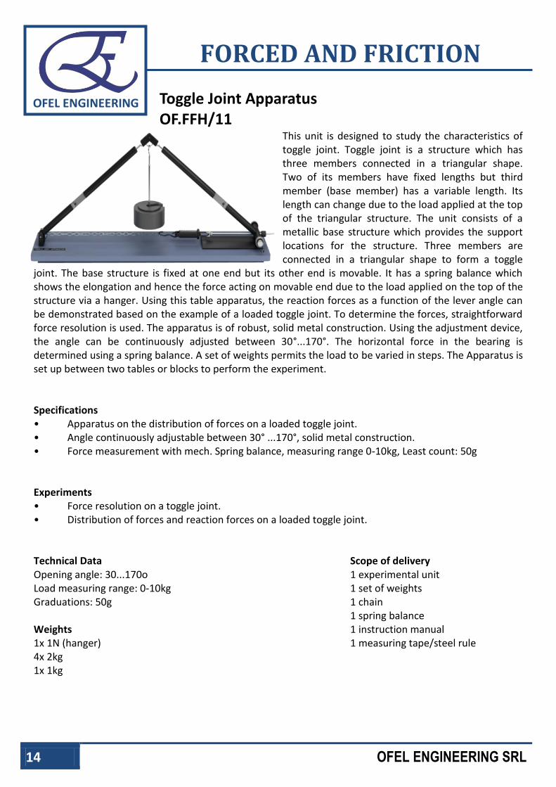
Toggle Joint Apparatus OF.FFH/11
This unit is designed to study the characteristics of toggle joint. Toggle joint is a structure which has three members connected in a triangular shape. Two of its members have fixed lengths but third member (base member) has a variable length. Its length can change due to the load applied at the top of the triangular structure. The unit consists of a metallic base structure which provides the support locations for the structure. Three members are connected in a triangular shape to form a toggle
joint. The base structure is fixed at one end but its other end is movable. It has a spring balance which shows the elongation and hence the force acting on movable end due to the load applied on the top of the structure via a hanger. Using this table apparatus, the reaction forces as a function of the lever angle can be demonstrated based on the example of a loaded toggle joint. To determine the forces, straightforward force resolution is used. The apparatus is of robust, solid metal construction. Using the adjustment device, the angle can be continuously adjusted between 30°...170°. The horizontal force in the bearing is determined using a spring balance. A set of weights permits the load to be varied in steps. The Apparatus is set up between two tables or blocks to perform the experiment. Specifications • Apparatus on the distribution of forces on a loaded toggle joint. • Angle continuously adjustable between 30° ...170°, solid metal construction. • Force measurement with mech. Spring balance, measuring range 0-10kg, Least count: 50g Experiments • Force resolution on a toggle joint. • Distribution of forces and reaction forces on a loaded toggle joint. Technical Data Scope of delivery Opening angle: 30...170o Load measuring range: 0-10kg Graduations: 50g Weights 1x 1N (hanger) 4x 2kg 1x 1kg
1 experimental unit 1 set of weights 1 chain 1 spring balance 1 instruction manual 1 measuring tape/steel rule
www.ofelitaly.com – [email protected] 15
OFEL ENGINEERING
FORCED AND FRICTION
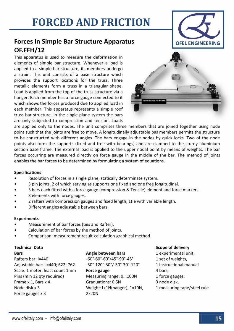
Forces In Simple Bar Structure Apparatus OF.FFH/12 This apparatus is used to measure the deformation in elements of simple bar structure. Whenever a load is applied to a simple bar structure, its members undergo a strain. This unit consists of a base structure which provides the support locations for the truss. Three metallic elements form a truss in a triangular shape. Load is applied from the top of the truss structure via a hanger. Each member has a force gauge connected to it which shows the forces produced due to applied load in each member. This apparatus represents a simple roof truss bar structure. In the single plane system the bars are only subjected to compression and tension. Loads are applied only to the nodes. The unit comprises three members that are joined together using node point such that the joints are free to move. A longitudinally adjustable bas members permits the structure to be constructed with different angles. The bars engage in the nodes by quick locks. Two of the node points also form the supports (fixed and free with bearings) and are clamped to the sturdy aluminium section base frame. The external load is applied to the upper nodal point by means of weights. The bar forces occurring are measured directly on force gauge in the middle of the bar. The method of joints enables the bar forces to be determined by formulating a system of equations. Specifications • Resolution of forces in a single plane, statically determinate system. • 3 pin joints, 2 of which serving as supports one fixed and one free longitudinal. • 3 bars each fitted with a force gauge (compression & Tensile) element and force markers. • 3 elements with force gauges. • 2 rafters with compression gauges and fixed length, 1tie with variable length. • Different angles adjustable between bars. Experiments • Measurement of bar forces (ties and Rafter). • Calculation of bar forces by the method of joints. • Comparison: measurement result-calculation-graphical method. Technical Data Scope of delivery Bars Rafters bar: l=440 Adjustable bar: L=440; 622; 762 Scale: 1 meter, least count 1mm Pins (min 12 qty required) Frame x 1, Bars x 4 Node disk x 3 Force gauges x 3
Angle between bars -60°-60°-60°/45°-90°-45° -30°-120°-30°/-30°-30°-120° Force gauge Measuring range: 0...100N Graduations: 0.5N Weight:1x1N(hanger), 1x10N, 2x20N
1 experimental unit, 1 set of weights, 1 instructional manual 4 bars, 1 force gauges, 3 node disk, 1 measuring tape/steel rule
16 OFEL ENGINEERING SRL
OFEL ENGINEERING
FORCED AND FRICTION
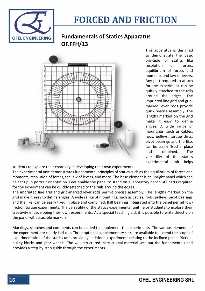
Fundamentals of Statics Apparatus OF.FFH/13
This apparatus is designed to demonstrate the basic principle of statics like resolution of forces, equilibrium of forces and moments and law of levers. Any part required to attach for the experiment can be quickly attached to the rails around the edges. The imprinted line grid and grid-marked lever rods provide quick precise assembly. The lengths marked on the grid make it easy to define angles. A wide range of mountings, such as cables, rods, pulleys, torque discs, pivot bearings and the like, can be easily fixed in place and combined. The versatility of the statics experimental unit helps
students to explore their creativity in developing their own experiments. The experimental unit demonstrates fundamental principles of statics such as the equilibrium of forces and moments, resolution of forces, the law of levers, and more. The base element is an upright panel which can be set up in portrait orientation. Feet enable the panel to stand on a laboratory bench. All parts required for the experiment can be quickly attached to the rails around the edges. The imprinted line grid and grid-marked lever rods permit precise assembly. The lengths marked on the grid make it easy to define angles. A wide range of mountings, such as cables, rods, pulleys, pivot bearings and the like, can be easily fixed in place and combined. Ball bearings integrated into the panel permit low-friction torque experiments. The versatility of the statics experimental unit helps students to explore their creativity in developing their own experiments. As a special teaching aid, it is possible to write directly on the panel with erasable markers. Markings, sketches and comments can be added to supplement the experiments. The various elements of the experiment are clearly laid-out. Three optional supplementary sets are available to extend the scope of experimentation of the statics unit, providing additional experiments relating to the inclined plane, friction, pulley blocks and gear wheels. The well-structured instructional material sets out the fundamentals and provides a step-by-step guide through the experiments.

www.ofelitaly.com – [email protected] 17
OFEL ENGINEERING
FORCED AND FRICTION
Specifications • Experimental setup to demonstrate simple, planar force systems. • Panel for easy mounting of various experimental components. • Panel with imprinted 50mm line grid and facility to write on using erasable marker. • 2 Lever rods with 50mm gird 600mm & 400mm lengths • Wide range of mountings: cables, rods, pulleys, pivot bearings and the like. • 2 weight sets. • Spring balance. Experiments • Accumulation and resolution of forces with force parallelogram. • Equilibrium of forces. • Law of levers, determination of moments and equilibrium of moments. • Combined lever systems. • Deflection and resolution of force by fixed and free pulleys. • With optional supplementary sets. • Inclined plane; for friction experiment. • Pulley blocks. • Gear wheels. Technical Data Panel wxh: 600x700 mm Line gride: 50 mm Spring balance Measuring range: 10kg Graduation: 50g
Weights 2x 5N (hangers) 6x 5N 2x 2N 1x1N 2x 0.5N Aluminum rail
Scope of delivery 1 experimental unit 1 thread 1 measuring tape/steel rule 2 set of weights 1 pulley 2 spring balance 2 torque disc 1 set of mountings

18 OFEL ENGINEERING SRL
OFEL ENGINEERING
FORCED AND FRICTION
Forces In Truss Apparatus OF.FFH/14
This unit is used to study the effect of load on various elements of truss. A truss is a structure which can bear high loads due to the fact that it has ability to divide the load among its elements. Therefore it becomes a reliable and stable structure. The unit consists of a metallic frame which provides the support locations for the truss structure. The elements of six different sizes are available to make desired structure of truss. These elements are joined together via pin joints. The objective of the experiment is to measure the bar forces in a single plane truss subjected to a single external force.
The Apparatus experimental set-up features bars with special pin install closures on their ends allowing them to be fixed easily into the node disc. The range of different bar lengths provided permits three forms of truss to be constructed. The bars are hinged, joined together by node discs, and are subjected only to compressive or tensile stress. No moments are transmitted in the nodes; they can be regarded as frictionless. Consequently, our trusses can be considered as ideal trusses. A load application device attached to a node disc generates an external force. All the forces on the truss bars are recorded by means of strain gauges. Computerised evaluation is provided by measurement amplifier (12 input channels). The software is used to manage the measurement data and provide graphical representation of the bar forces. The software features a comprehensive help function. The various elements of the experiment are clearly laid-out and housed securely in a storage system. The complete experimental set-up is arranged in the frame. The instructional material sets provides a step-by-step guide through the experiment.
www.ofelitaly.com – [email protected] 19
OFEL ENGINEERING
FORCED AND FRICTION
Specifications • Investigation of bar forces in a statically determinate truss. • Construction of various trusses possible. • 2 supports with node discs. • Load application device with force gauge mountable on different node discs. • Strain gauge to measure force on each bar. • Software to evaluate measurement data. • Storage system to house the components. • Experimental set-up in frame. Experiments • Measurement of the bar forces in various single Plane trusses. • Dependency on the external force.
* direction * point of application.
• Comparison of measurement results with mathematical methods. * Method of joints * Ritter's method of sections
• Basic principle: measurement of forces using load cell (strain gauges). Technical Data Bars 1x150mm, 3x 259mm, 7x 300mm 1x 397mm, 3x 424mm, 1x 520mm Angle between bars: 30o, 45o, 60o, 90o Maximum bar force: 500N Load cell on each bar Load application device -500...+500N Graduations: 0.01N Software Load cell installed on each member to display the force in different member of truss. Scope of delivery 1 set of bars 5 node disks 2 supports with node disks 1 load application device 1 set of cables 1 instruction manual 1 CD of software

20 OFEL ENGINEERING SRL
OFEL ENGINEERING
FORCED AND FRICTION
Two Arm Lever OF.FFH/15
This apparatus is designed to demonstrate the equilibrium of moment of two arm lever. Moment occurring at the both ends of the lever is balanced by applying load at different distances from the central pivoted point. In this apparatus beam is centrally mounted by the vertically support so this beam act as two arm lever. Lever is scaled and riding weights are provided at both ends of the lever. Equilibrium is achieved by applying load on both side of the arms and adjusting their distance from mean position.
Specifications • Investigation of the equilibrium of moments on a two-arm lever. • Ball bearing-mounted beam with integrated scale as two-arm lever. • 3 sets of weights. • Sturdy metal frame. Experiments • Fundamentals of the equilibrium of moments: applied forces, generated moments and equilibrium. • Action of forces dependent on the lever arm. Technical Data Beam l x w x h: 600x30x10mm, centrally ball bearing mounted Lever length: 2x300mm Weights 3x 0.5N (hangers) 6x 5N 12x 1N 6x 2N Riders 3 riders with hooks
Scope of delivery 1 experimental unit, 3 set of weights, 3 riders, 1 instruction manual

www.ofelitaly.com – [email protected] 21
OFEL ENGINEERING
FORCED AND FRICTION
Polygon And Forces Apparatus OF.FFH/16 This apparatus is majorly a round disc which is placed horizontally on three legs attached to a foundation. A 360 protractor is set centrally on the plate and pulleys on clamps permit the load hanger cords to run toward a ring dropped over the center. The apparatus is best to express the conditions of equilibrium of coplanar forces acting on a circular disc. Conditions of equilibrium can be obtained by centralizing a small ring available over the central pin with cords to load hangers where the loads and lines of action are variable. In this way, it is possible to construct the multiple of forces in equilibrium and to find the resultant forces. A simple but elegant demonstration of the conditions of equilibrium for three or more coplanar forces acting either at a point, on a circular disc or on a rectangular shape. Up to five loads can be applied to the chosen shape by setting up pulleys at various angular positions. The lines of action of the forces are recorded by drawing along the weighted cords onto a piece of paper attached to the pulley table. A range of experiments is possible, investigating concurrent and non concurrent coplanar forces acting on simple shapes, comparing the experimental values with the relevant polygons of force. A complete instruction manual is provided describing the apparatus, its application, experimental procedure and typical test results. Specifications • Self-contained, bench mounted. • Direct measurement of forces. • Adjustable lines of action of forces. • Practical verification of triangle of forces, polygon of forces and link polygon. • Demonstrates equilibrium of forces at a point,
applied to various points round a disc or acting on a rectangular lamina. • Concurrent & Non-concurrent coplanar forces. • Calibrated Weights. • User Manual with Sample Readings. Experiments • To resolve by experiment any suitable system of static coplanar forces which may or may not be concurrent. • To verify graphically using:
a) Triangle of forces for three or more than three concurrent coplanar forces.
b) Polygon of forces for more than three concurrent coplanar forces. c) Link polygon for three or more non-concurrent coplanar forces.
• To investigate (c) for either a disc or a rectangular shape. • To compare the accuracy of the experiment by comparing the experimental and graphical results.
Scope of delivery 1 instruction manual 5 set of weights 1 thread 5 pulleys 1 experimental unit 1 ring

22 OFEL ENGINEERING SRL
OFEL ENGINEERING
FORCED AND FRICTION
Work Done By Variable Force Apparatus OF.FFH/17
The apparatus consists of the arm, hanger with loads, spring balance and protractor scale attached to the support board. The apparatus mainly focuses on the fact that work done by a variable force can be determined by measuring the area under the graph of force and distance travelled. One end of the arm is fixed and its position is indicated by the protractor. Other end of arm carries the load hanger, and is restrained by spring balance that is perpendicular to the arm. Under the application of load, the movement of arm can be read easily. This experiment is designed to reinforce the general principle that the work done, particularly by a variable force, can be determined simply by measuring the area under the graph of force and distance moved.
Vertical Force The apparatus is a simple lifting mechanism with obvious non linear characteristics. A suspension cord carrying a loaded trolley at mid span is tensioned by passing the cord over a pulley at one end and down to a weight hanger. As the vertical effort is increased, the tensioned cord will move to a new equilibrium position lifting the loaded trolley. Heights of the load and effort are measured relative to the base. All the pulleys are fitted with ball bearings to minimize friction effects.
Tangential Force A pivoted arm carrying a load hanger at its end is restrained by a force gauge at right angles to the arm. The angular position of the arm is indicated by a protractor scale attached to the backboard. The effort is the force needed to hold the weighted arm at a particular angle. This can be repeated for several different weights.
Specifications • Table unit for experiments on mechanical work and potential energy. • Lifting a weight using a lever and a dynamometer (spring balance). • Integrated angle measuring scale protractor. Experiments • To obtain the experimental relationship between effort and distance moved by effort, and to compare with a theoretical prediction. • To show that the work done is the area under a graph of load against distance moved. Technical Data Weights 2x 0.5N 2x 1N 2x 2N 2x 5N
Spring balance 0....100N Graduation: 0.5N
Scope of delivery 2 set of weights 1 thread 1 spring balance 2 hangers 3 pulleys

www.ofelitaly.com – [email protected] 23
OFEL ENGINEERING
FORCED AND FRICTION
Coriolis Force Apparatus OF.FFH/18 The Coriolis effect is defined as the apparent deflection of objects moving in a straight path relative to the earth's surface. Its strength is proportional to the speed of the earth's rotation at different latitudes but it has an impact on moving object across the globe. A horizontal rotating arm sits on top of the main base unit and rotates in a horizontal plane. Rotating arm has a water tank with submersible pump which projects a jet of water in to radial direction. The degree of deflection can be measured by means of the scale on water tank. Instrumentation is done for the display of speed of water jet & speed of rotation of horizontal arm. Specifications • Deflection of a water jet in radial direction dependent on the speed and direction of rotation • Rotating reference frame consisting of transparent water tank with
submersible pump on a rotating arm. • Scale to read the deflection of the water jet. • Closed water circuit. • Speed sensor with digital display. Experiments • Inertial or apparent force. • Interference of a rotational movement on
a translational movement. • Visualisation of the Coriolis force effect. Technical Data
Rotating arm Infinitely adjustable speed: 0...60min-1 Submersible pump Max. Flow rate 10L/min
Required for Operation 230V, 50/60Hz, 1 phase Effect of the Coriolis force:
A starting point of the moving mass, Fc Coriolis force; orange: rotating reference frame, red: direction of the Coriolis force, green: current motion of the mass, dashed blue: direction of movement without rotation, blue: actual direction of movement with rotation.
Scope of delivery 1 experiment unit 1 power cord 1 instructional manual
1 nozzle for water jet, 2 pump, 3 tank, 4 deflected water jet, 5 pivot point of the arm, 6 water jet with a stationary arm, 7 direction of rotation; A starting point of the moving mass
24 OFEL ENGINEERING SRL
OFEL ENGINEERING
FORCED AND FRICTION
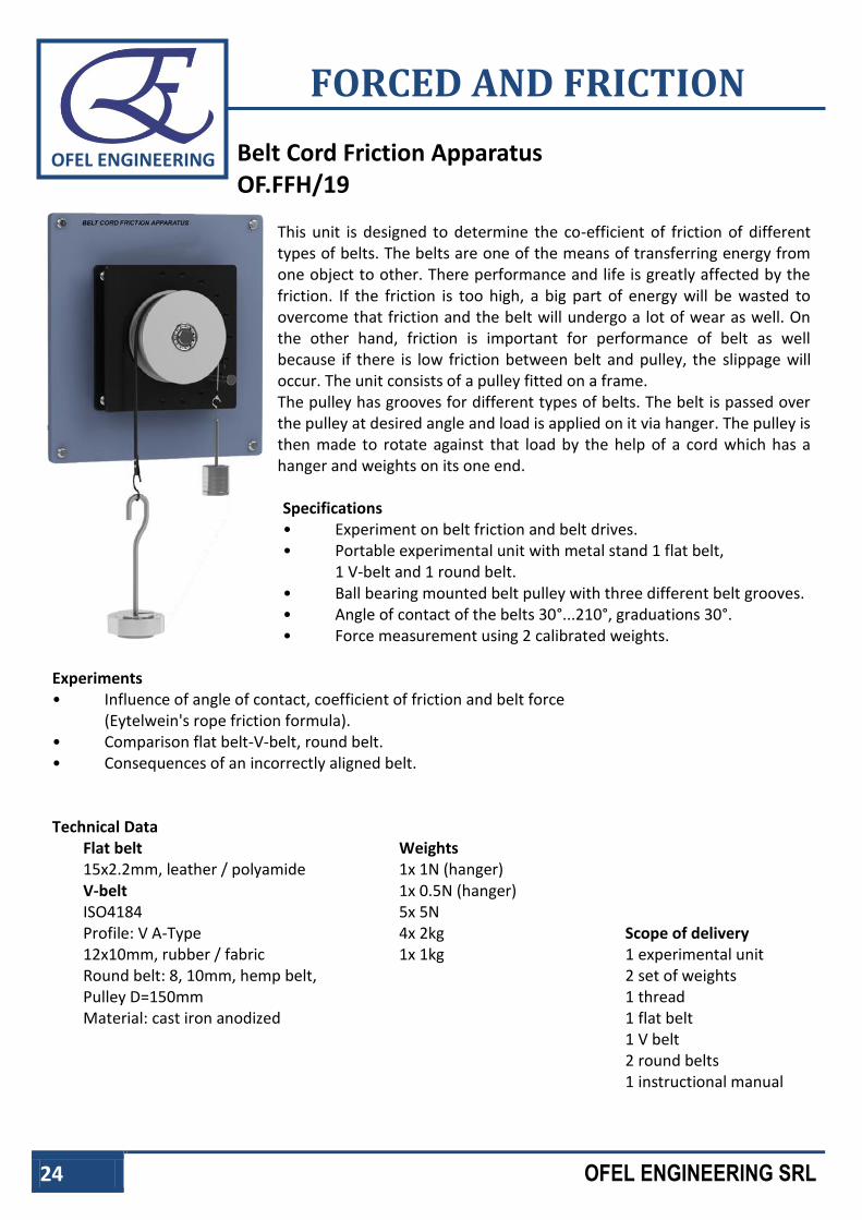
Belt Cord Friction Apparatus OF.FFH/19
This unit is designed to determine the co-efficient of friction of different types of belts. The belts are one of the means of transferring energy from one object to other. There performance and life is greatly affected by the friction. If the friction is too high, a big part of energy will be wasted to overcome that friction and the belt will undergo a lot of wear as well. On the other hand, friction is important for performance of belt as well because if there is low friction between belt and pulley, the slippage will occur. The unit consists of a pulley fitted on a frame. The pulley has grooves for different types of belts. The belt is passed over the pulley at desired angle and load is applied on it via hanger. The pulley is then made to rotate against that load by the help of a cord which has a hanger and weights on its one end.
Specifications • Experiment on belt friction and belt drives. • Portable experimental unit with metal stand 1 flat belt, 1 V-belt and 1 round belt. • Ball bearing mounted belt pulley with three different belt grooves. • Angle of contact of the belts 30°...210°, graduations 30°. • Force measurement using 2 calibrated weights.
Experiments • Influence of angle of contact, coefficient of friction and belt force
(Eytelwein's rope friction formula). • Comparison flat belt-V-belt, round belt. • Consequences of an incorrectly aligned belt. Technical Data
Flat belt 15x2.2mm, leather / polyamide V-belt ISO4184 Profile: V A-Type 12x10mm, rubber / fabric Round belt: 8, 10mm, hemp belt, Pulley D=150mm Material: cast iron anodized
Weights 1x 1N (hanger) 1x 0.5N (hanger) 5x 5N 4x 2kg 1x 1kg
Scope of delivery 1 experimental unit 2 set of weights 1 thread 1 flat belt 1 V belt 2 round belts 1 instructional manual

www.ofelitaly.com – [email protected] 25
OFEL ENGINEERING
FORCED AND FRICTION
Drum Friction Apparatus OF.FFH/20 In this apparatus drum is wounded by the cord externally, is machined to plain aluminum. A cord is wrapped around the perimeter of the brake drum and the free end of the cord terminates with a load hanger. Torque is applied to the brake drum by using the calibrated weights set provided and the load hanger. Mounted inside the brake drum is a single brake shoe with its own pivot. A second cord connects to the brake shoe again terminates at the load hanger. As the load is applied to the brake shoe so that friction force increases. The student must then add load to the torque hanger to try and rotate the brake drum at near constant speed. The sense of rotation of the torque determines whether the single brake shoe acts as a leading or trailing shoe. Direct comparison of tangential force and braking load is obtained and the coefficient of friction determined. Specification • Brake drum apparatus with single shoe. • To have drum torque and braking load applied by weight hangers and cords. • Used in the determination of coefficient of friction. • To be a simulation of a real brake system. • To have simple transition from leading to trailing brake shoes. Experiments • To determine experimentally the variation of tangential force with braking load. • To obtain the coefficient of friction between the aluminium drum and the brake shoe. • To compare leading and trailing shoes. Technical Data Weights 5x 5N 4x 2N 4x 1N 2X 0.5N 1x 1N (hanger) 1x 0.5N (hanger) Drum internal dia 130mm
Scope of delivery 1 thread 2 sets of weights 2 hangers 1 experimental unit 1 brake shoe 1 brake drum

26 OFEL ENGINEERING SRL
OFEL ENGINEERING
FORCED AND FRICTION
Bearing Friction Apparatus OF.FFH/21
This apparatus is designed to demonstrate the categorical difference between sliding and rolling friction and its application for different industrial uses. Apparatus uses different types of plain and rolling bearing of different materials like iron and bronze. Apparatus includes flywheel mounted upon an axle. Axle is supported in a plain or ball bearing and bearing housing is attached with wall bracket. Torque is applied by putting dead weights on the flywheel using hanger which corresponds to the frictional torque when motion begins. Bearing Friction provides experiments relating to friction on sliding and rolling bearings. Bearing shells in various materials serve as sliding bearings. Bearing forces are generated by the dead-weight of a heavy flywheel. A torque is applied by means of weights which correspond to the frictional torque when the motion begins. When the rolling bearings are used the bearing friction is very low. In this case the flywheel can be used for fundamental experiments in rotational dynamics. The unit is intended for mounting on a laboratory wall.
Specifications • Experiment in sliding bearing friction with various material pairings and
comparison with rolling bearings. • 3 different bearing materials for sliding bearing shells. • Stainless steel shaft. • Flywheel of galvanised steel. • Drive by cable drum and weight set. • Base plate of anodised aluminium. • Experiments in rotational dynamics possible. Experiments • Determination of friction torque on sliding bearings: various material pairings by
means of interchangeable bearing shells. • Determination of the friction torque on a rolling bearing. • Comparison between sliding and rolling bearing. • Fundamental experiments in rotational dynamics. Technical Data Bearing material Gun metal, Cast Iron, PTFE Grooved ball bearing: type 6203 Bearing journal of shaft: d=17mm Flywheel d=300mm Weight: 22.2kg
Weights 1x 1N (hanger) 5x 1N 1x 2N 3x 5N
Scope of delivery 1 set of weights, 1 hanger, 1 thread, 4 roller bearings 1 set of instruction manual 3 sets of sloding bearings (1 set contains two bearing)
www.ofelitaly.com – [email protected] 27
OFEL ENGINEERING
FORCED AND FRICTION
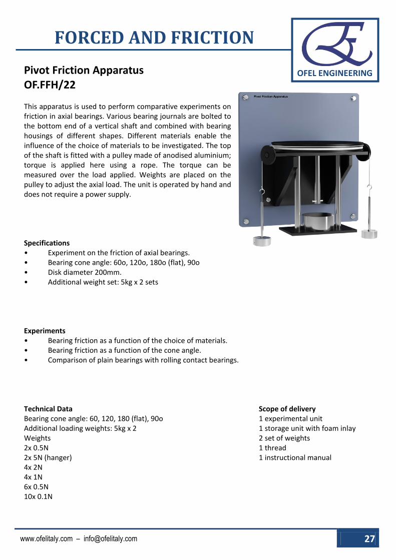
Pivot Friction Apparatus OF.FFH/22 This apparatus is used to perform comparative experiments on friction in axial bearings. Various bearing journals are bolted to the bottom end of a vertical shaft and combined with bearing housings of different shapes. Different materials enable the influence of the choice of materials to be investigated. The top of the shaft is fitted with a pulley made of anodised aluminium; torque is applied here using a rope. The torque can be measured over the load applied. Weights are placed on the pulley to adjust the axial load. The unit is operated by hand and does not require a power supply. Specifications • Experiment on the friction of axial bearings. • Bearing cone angle: 60o, 120o, 180o (flat), 90o • Disk diameter 200mm. • Additional weight set: 5kg x 2 sets Experiments • Bearing friction as a function of the choice of materials. • Bearing friction as a function of the cone angle. • Comparison of plain bearings with rolling contact bearings. Technical Data Bearing cone angle: 60, 120, 180 (flat), 90o Additional loading weights: 5kg x 2 Weights 2x 0.5N 2x 5N (hanger) 4x 2N 4x 1N 6x 0.5N 10x 0.1N
Scope of delivery 1 experimental unit 1 storage unit with foam inlay 2 set of weights 1 thread 1 instructional manual

28 OFEL ENGINEERING SRL
OFEL ENGINEERING
FORCED AND FRICTION
Clutch Plate Friction Apparatus OF.FFH/23
Clutch plates are used to connect and disconnect driven part from the driving part temporarily. This apparatus demonstrates the concept of clutch friction using different types of clutch plates. It consists of flat disc of leather against which a clutch plate is loaded. The clutch plate is secured by screws to the effort pulley. A torque is applied to the effort pulley by dead weight using two load cords. The main load on the effort pulley and thus the clutch plate is applied by a loading arm system via a thrust bearing. Specifications • The clutch plate set consists of 4 plates with
the different dimensions. • Different type of surfaces for friction.
Experiments • To investigate the behavior of flat clutch plates. • To investigate the Behavior of different clutch plates of different Materials. • Comparison of different methods of calculation. Technical Data Dimension Length: 275mm Width: 195mm Height: 300mm Disk diameter: 250mm Disk material: mild steel, asbestos, anodised aluminium
Pulley 2 pulleys Diameter: 25mm
Weights: A set of weight for loading and effort to perform the Experiment will be provided with the apparatus. 2x 1N (hanger) 8x 5N - 6x 2N - 4x 1N Additional weight 2x 30N
Scope of delivery 1 experimental unit 4 friction discs 2 additional weights 2 set of weights 1 thread 1 instructional manual

www.ofelitaly.com – [email protected] 29
OFEL ENGINEERING
FORCED AND FRICTION
Dry, Rough and Lubricated Friction Apparatus OF.FFH/24 The apparatus consists of a main shaft with three identically dimensioned discs fixed on to it. The variable between the discs are their test surfaces. One disc is plain (fine machined surface) the second is the same but has a tub underneath that can be filled with a grease or liquid lubricant and the third disc has a rough finish. The main shaft has a pulley fixed on the end to which an effort load can be applied to overcome the normal force between the contacting surfaces. The apparatus has a braking lever which can be positioned over one of the testing discs at a time. The breaking lever has the capacity to hold a variety of test samples made from different materials as well as a roller bearing that is supplied with the unit. With the breaking force set the effort hanger’s mass is increased until the pulley starts to rotate and the masses fall at a constant rate. From this, forces can be calculated and a friction coefficient for the brake material or other material and disc surface can be represents as a graphical representation or calculated. Specifications • Wall or Frame Mounted apparatus. • To show the coefficient of different materials upon various disc surfaces. • To determine the equilibrium of forces between the force of friction and normal force between contacting surfaces. • 3 friction discs with various surfaces to experiment with: Dry, rough and lubricated. • Break lever with 5 different materials and roller bearing that can be used on each friction disk. • Sliding materials: Steel, brass, nylon, brake lining and rubber. • Pulley, two hangers and cord provided. • Operating and maintenance manual with instructions for testing of the unit and example results to compare with.
Experiments • To determine the coefficient of sliding friction under different conditions between various materials and disc surfaces. • To measure the force (torque) required to turn a static shaft against gravity and friction. • To show the equilibrium of forces (between the force of friction and normal force between contacting surfaces) in a rolling system. • To show how breaking/loading force affects effort required and friction coefficient.
Technical Data Weights 2x 0.5N (hanger) 4x 5N 4x 2N 2x 1N 2x 0.5N
Scope of delivery 1 experimental unit 1 thread 2 set of weights 5 slinding materials 1 instructional manual

30 OFEL ENGINEERING SRL
OFEL ENGINEERING
FORCED AND FRICTION
Equilibrium of Parallel Forces Apparatus OF.FFH/25
A force board is clamped into the Universal Frame and Stand. Two acrylic models engraved to simulate a ‘Warren’ and an ‘N’ truss are used for the application of vertical loads and reactions. The forces are produced with cords tensioned by weights on hangers, double pulleys being used to turn the up ward forces downward. A circular disc with twelve attachment points is used for the couples. To simplify the results each acrylic model has a counter balancing weight to render each one ‘weightless’. The lines of action of the cords can be transferred onto a sheet of paper clipped to the force board. The set of weights needed for the experiment is included. A comprehensive instruction manual for full details on apparatus assembly and operation as well as example results. All necessary assembly and operational tools are provided.
Experiments • Verify the conditions of equilibrium when sets of parallel forces act in one plane on a rigid
body Fv = 0 (where F = forces and V = vertical). • Special case where equal and opposite parallel forces produce a couple acting on a body. • Equilibrium of opposing couples. • Experimental verification of the use of a link polygon and is a test of M = 0 (where M = moments). Specifications • Two acrylic models shaped and engraved to simulate a ‘Warren’ and an ‘N’ truss are used
for the application of vertical loads and reactions. • A circular disc of Perspex provided to offer 12 peripheral attachment points for applying
opposing couple. • The forces produced by nylon cords tensioned by weights on hangers, pulleys being used to
turn the cords vertically downward. • The lines of force to be transferred onto A1 paper sheet (not supplied) clipped to the force board. • Each Perspex model has a counterbalancing weight to render each one ‘weight less’. Technical Data Weights 5x 0.5N (hanger) 10x 5N 10x 2N 10x 1N 10x 0.5N
Scope of delivery 1 experimental unit 1 instructional manual 5 set of weights 1 thread 2 rings

www.ofelitaly.com – [email protected] 31
OFEL ENGINEERING
FORCED AND FRICTION
Fletcher Trolley Apparatus OF.FFH/26
The Fletcher’s Trolley used to observe the two forces that work on and against each other in a vector. The experiment observes that principles of Newton’s second law of motion. Newton’s second law states that the acceleration of an object is directly proportional to the unbalanced force acting on it and indirectly proportional to its mass. The principle will be shown through the different masses that will be placed on a cart and hanging mass because as the hanging mass increases, the acceleration of the object being pulled should also increase. Experiments • Newton’s second law Specification • Light metal track 1720x150min wide with leveling feet covered with stops at either end, aluminum
pulley 50mm dia., Clamp for vibrator and automatic Pen release. Metal trolley with three wheels mounted on ball bearings. Five hooks to accommodate cylindrical masses approximate 350gm. Vibrator 60mm long with clamping works at 5 and 8Hz and Pen holder to take fiber tip type of pen.
Technical Data Frequency = 5 Hz Plane length = 1450 mm Plane width = 120 mm Trolley Dimension Length = 585 mm Width = 76 mm Height = 65 mm Masses Trolley mass = 1.07 kg Additional Weights = 0.5 kg x 5 Hanger mass = 0.5 N x 1 Weights = 0.5 N x 6
Scope of delivery 1 experimental unit 1 thread 1 set of weight 5 additional weights 1 instructional manual
32 OFEL ENGINEERING SRL
OFEL ENGINEERING
FORCED AND FRICTION
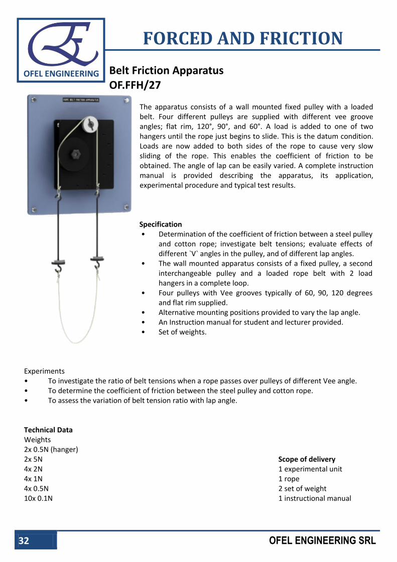
Belt Friction Apparatus OF.FFH/27
The apparatus consists of a wall mounted fixed pulley with a loaded belt. Four different pulleys are supplied with different vee groove angles; flat rim, 120°, 90°, and 60°. A load is added to one of two hangers until the rope just begins to slide. This is the datum condition. Loads are now added to both sides of the rope to cause very slow sliding of the rope. This enables the coefficient of friction to be obtained. The angle of lap can be easily varied. A complete instruction manual is provided describing the apparatus, its application, experimental procedure and typical test results.
Specification • Determination of the coefficient of friction between a steel pulley
and cotton rope; investigate belt tensions; evaluate effects of different `V` angles in the pulley, and of different lap angles.
• The wall mounted apparatus consists of a fixed pulley, a second interchangeable pulley and a loaded rope belt with 2 load hangers in a complete loop.
• Four pulleys with Vee grooves typically of 60, 90, 120 degrees and flat rim supplied.
• Alternative mounting positions provided to vary the lap angle. • An Instruction manual for student and lecturer provided. • Set of weights.
Experiments • To investigate the ratio of belt tensions when a rope passes over pulleys of different Vee angle. • To determine the coefficient of friction between the steel pulley and cotton rope. • To assess the variation of belt tension ratio with lap angle. Technical Data Weights 2x 0.5N (hanger) 2x 5N 4x 2N 4x 1N 4x 0.5N 10x 0.1N
Scope of delivery 1 experimental unit 1 rope 2 set of weight 1 instructional manual

www.ofelitaly.com – [email protected] 33
OFEL ENGINEERING
FORCED AND FRICTION
Belt Drive and Belt Friction OF.FFH/28 The belt drives are machine elements that are classed as traction mechanisms in the field of transmission or conversion elements. They transfer torque and speed between guiding members such as wheels or pulleys. The motion is transferred by traction mechanisms that can only absorb tensile forces. Toothed belts and chains deliver positive transmission of movements. Traction mechanisms such as cables, flat belts and V-belts, on the contrary, allow for non-positive transmission. In non-positive belt drives, the circumferential force between the belt and the pulley is transmitted according to the principle of cable friction. Cable friction arises due to tangential static-friction forces at the points where the cable is in contact with the wheel or the pulley. Eytelwein’s cable friction formula is used to calculate both cable and belt friction. The pulley is mounted on ball bearings and is powered by a crank handle. Its flywheel mass favours an even rotation of the pulley. Two spring balances detect the tensile forces on the respective belt ends. This makes it possible to precisely adjust the belt tension using a threaded spindle. One flat belt, a V-belt and a cable belong to the scope of delivery. Specification • Function of a belt drive. • Belt friction and comparison of different belt materials and types. • Ball-bearing mounted pulley with 3 different belt grooves. • 1 flat belt, 1 V-belt and 1 cable. • Wrap angle of the belts 30°......180°, graduation 1°. • Force measurement with 2 spring balances. Experiments • Effect of wrap angle, coefficient of friction and cable force (Eytelwein’s belt friction formula). • Comparison of flat belts and V-belts. • Consequences of an unadapted V-belt groove. Technical Data
Flat belts: 1x leather/polyamide, 15x2.2mm V-belt ISO 4184 Profile: SPZ 12x10mm, rubber/fabric F=300mm
Cable: Hemp, F=8, 10mm Pulley Material: grey iron Spring balance 10kg; Least count 50g Weights 1x 1N (hanger), 4x 2kg, 1x 1kg
Scope of delivery 1 experimental unit, 1 spring balance 1 set of weights, 1 thread 3 types of belts, 1 set of instruction manual

34 OFEL ENGINEERING SRL
OFEL ENGINEERING
FORCED AND FRICTION