forced circulation boilers - orkli, suelo radiante ... acumulador solar (eng).pdf · considering...
TRANSCRIPT
Forced Circulation BoilersInstallation, maintenance & use instructions
TECHNICAL MANUAL


3The company preserves the right to change all specifications of the products and their accessories without prior notice
FORCED CIRCULATION BOILERS
CONTENTS
GENERAL INFORMATION .......................................................................................................................................... 4
DOMESTIC HOT WATER CONSUMPTION ............................................................................................................... 4
SOLAR WATER HEATING .......................................................................................................................................... 4
FORCED CIRCULATION SYSTEMS .......................................................................................................................... 5
LABELING ................................................................................................................................................................... 6
WATER TANK TECHNICAL DATA ............................................................................................................................... 6
GENERAL INSTALLATION RULES ............................................................................................................................ 8
INSTALLATION POSITION ......................................................................................................................................... 9
GENERAL PREVENTION MEASURES .................................................................................................................... 10
INSTRUCTIONS FOR THE INTERCONNECTION OF COLLECTORS IN SOLAR FIELDS ................................... 10
RECOMMENDATIONS ON HEAT TRANSFER MEANS AND SAFETY AND PROTECTIONMEASURES DURING FILLING, OPERATION AND MAINTENANCE OF THE SYSTEM ........................................ 11
MAXIMUM OPERATING PRESSURE, PRESSURE DROP, MAXIMUM AND MINIMUM ANGLE ............................ 11
FORCED CIRCULATION SYSTEMS OPERATION AND INSTALLATION ................................................................ 12
WATER TANK CONNECTION .................................................................................................................................. 13
RECIRCULATION CONNECTION ............................................................................................................................ 13
CLOSED LOOP PIPING ............................................................................................................................................ 14
POST INSTALLATION INSTRUCTIONS ................................................................................................................... 14
CHECK LIST ............................................................................................................................................................. 15
4 The company preserves the right to change all specifications of the products and their accessories without prior notice
GENERAL INFORMATIONIn the present manual you will find all necessary instructions with regard to the installation, operation andmaintenance of the product. The company is active in the Solar Energy with high-tech equipment, ultra-modern facilities and certified products of high quality. Our experience and know-how support our co operations, before and after sales, both in Europe and internationally.
Nowadays, the necessity for production and saving of energy without at the same time polluting the environment has become common knowledge. The planetʼs conventional energy resources are diminishing to a threatening level as our societyʼs energy requirements are increasing, generating pollutants that affect the climateʼs balance. Renewable energy sources promise a solution to the energy problem as well as to pollution. Gradually, the international legislation is changing and encouraging - or even imposing - the use of alternative energy products, with the aim to satisfy energy requirements without endangering the environment.
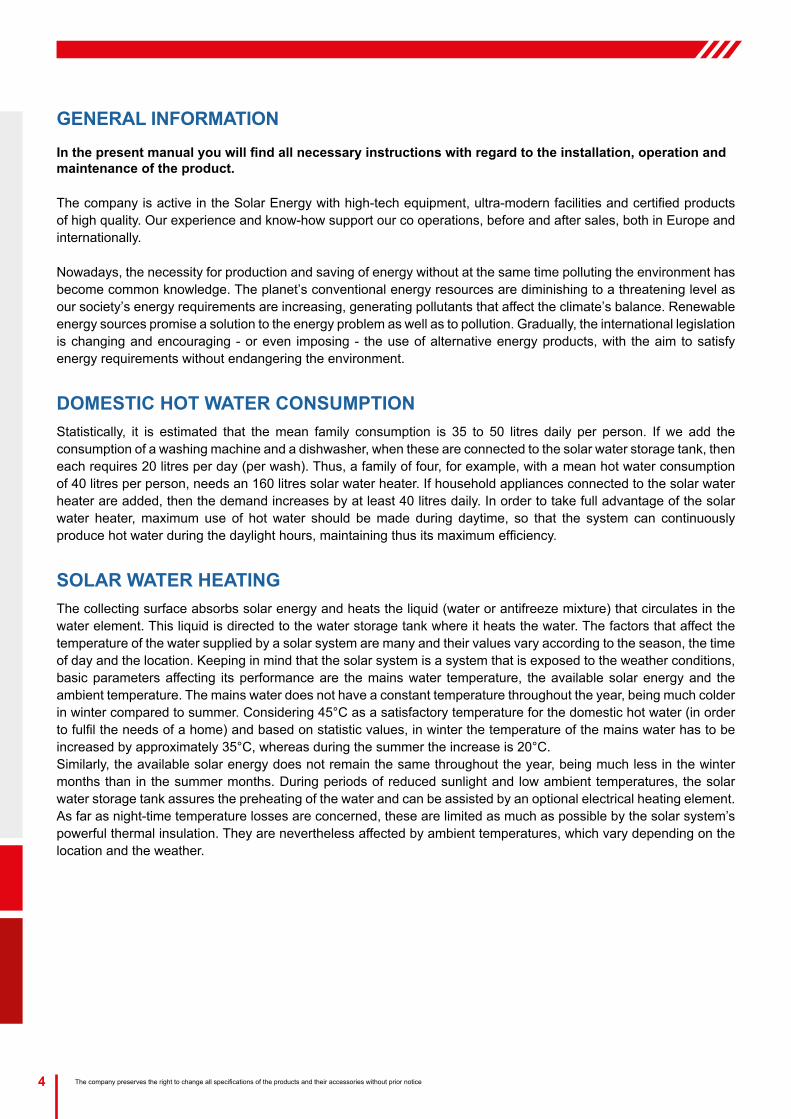
DOMESTIC HOT WATER CONSUMPTIONStatistically, it is estimated that the mean family consumption is 35 to 50 litres daily per person. If we add the consumption of a washing machine and a dishwasher, when these are connected to the solar water storage tank, then each requires 20 litres per day (per wash). Thus, a family of four, for example, with a mean hot water consumption of 40 litres per person, needs an 160 litres solar water heater. If household appliances connected to the solar water heater are added, then the demand increases by at least 40 litres daily. In order to take full advantage of the solar water heater, maximum use of hot water should be made during daytime, so that the system can continuously produce hot water during the daylight hours, maintaining thus its maximum efficiency.
SOLAR WATER HEATINGThe collecting surface absorbs solar energy and heats the liquid (water or antifreeze mixture) that circulates in the water element. This liquid is directed to the water storage tank where it heats the water. The factors that affect the temperature of the water supplied by a solar system are many and their values vary according to the season, the time of day and the location. Keeping in mind that the solar system is a system that is exposed to the weather conditions, basic parameters affecting its performance are the mains water temperature, the available solar energy and the ambient temperature. The mains water does not have a constant temperature throughout the year, being much colder in winter compared to summer. Considering 45°C as a satisfactory temperature for the domestic hot water (in order to fulfil the needs of a home) and based on statistic values, in winter the temperature of the mains water has to be increased by approximately 35°C, whereas during the summer the increase is 20°C.Similarly, the available solar energy does not remain the same throughout the year, being much less in the winter months than in the summer months. During periods of reduced sunlight and low ambient temperatures, the solar water storage tank assures the preheating of the water and can be assisted by an optional electrical heating element. As far as night-time temperature losses are concerned, these are limited as much as possible by the solar system’s powerful thermal insulation. They are nevertheless affected by ambient temperatures, which vary depending on the location and the weather.

5The company preserves the right to change all specifications of the products and their accessories without prior notice
FORCED CIRCULATION BOILERS
FORCED CIRCULATION SYSTEMS
Ecology - Economy - Aesthetic - Efficiency - Autonomy
With the use of solar forced circulation systems we can achieve energy savings of 70-100%, as the operating time of the boiler or the heating element is reduced dependent on the sunlight of every region and the system’s size, while at the same time the carbon dioxide emissions are reduced.Central solar systems are made of excellent materials according to international specifications and have all the certificates and tests that attest their quality.They are highly aesthetic systems, which can be simply and quickly installed to blend with the traditional or modern architecture of a building, providing free hot water almost the whole year round. Even in regions with low sunlight they achieve the preheating of the water, which contributes to a drastically reduced consumption of conventional energy.
6 The company preserves the right to change all specifications of the products and their accessories without prior notice
PRODUCT RANGE
DESCRIPTIONBoiler 160ltBoiler 300lt
MODELORKLI V-04212ORKLI V-04213
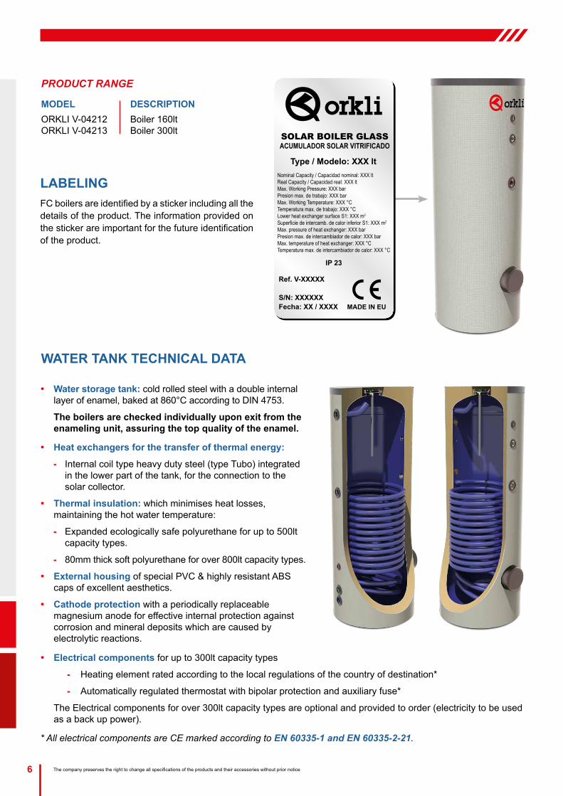
LABELING FC boilers are identified by a sticker including all the details of the product. The information provided on the sticker are important for the future identification of the product.
SOLAR BOILER GLASSACUMULADOR SOLAR VITRIFICADO
Type / Modelo: XXX lt
Ref. V-XXXXX
S/N: XXXXXXFecha: XX / XXXX
IP 23
Nominal Capacity / Capacidad nominal: XXX ltReal Capacity / Capacidad real: XXX ltMax. Working Pressure: XXX barPresion max. de trabajo: XXX barMax. Working Temperature: XXX °CTemperatura max. de trabajo: XXX °CLower heat exchanger surface S1: XXX m2
Superficie de intercamb. de calor inferior S1: XXX m2
Max. pressure of heat exchanger: XXX barPresion max. de intercambiador de calor: XXX barMax. temperature of heat exchanger: XXX °CTemperatura max. de intercambiador de calor: XXX °C
MADE IN EU
WATER TANK TECHNICAL DATA
y Electrical components for up to 300lt capacity types
- Heating element rated according to the local regulations of the country of destination*
- Automatically regulated thermostat with bipolar protection and auxiliary fuse*
The Electrical components for over 300lt capacity types are optional and provided to order (electricity to be used as a back up power).
* All electrical components are CE marked according to EN 60335-1 and EN 60335-2-21.
y Water storage tank: cold rolled steel with a double internal layer of enamel, baked at 860°C according to DIN 4753.
The boilers are checked individually upon exit from the enameling unit, assuring the top quality of the enamel.
y Heat exchangers for the transfer of thermal energy:
- Internal coil type heavy duty steel (type Tubo) integrated in the lower part of the tank, for the connection to the solar collector.
y Thermal insulation: which minimises heat losses, maintaining the hot water temperature:
- Expanded ecologically safe polyurethane for up to 500lt capacity types.
- 80mm thick soft polyurethane for over 800lt capacity types.
y External housing of special PVC & highly resistant ABS caps of excellent aesthetics.
y Cathode protection with a periodically replaceable magnesium anode for effective internal protection against corrosion and mineral deposits which are caused by electrolytic reactions.
7The company preserves the right to change all specifications of the products and their accessories without prior notice
FORCED CIRCULATION BOILERS
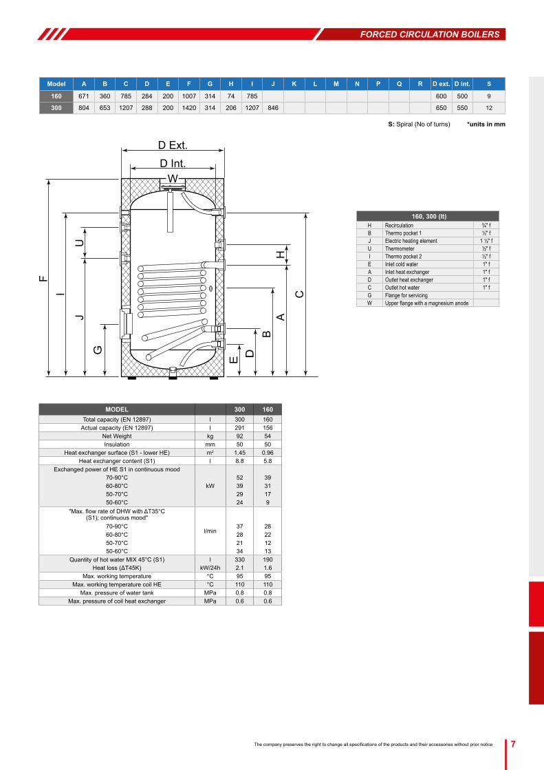
Model A B C D E F G H I J K L M N P Q R D ext. D int. S
160 671 360 785 284 200 1007 314 74 785 600 500 9
300 804 653 1207 288 200 1420 314 206 1207 846 650 550 12
S: Spiral (No of turns) *units in mm
160, 300 (lt)H Recirculation ¾″ fB Thermo pocket 1 ½″ fJ Electric heating element 1 ½″ fU Thermometer ½″ fI Thermo pocket 2 ½″ fE Inlet cold water 1″ fA Inlet heat exchanger 1″ fD Outlet heat exchanger 1″ fC Outlet hot water 1″ fG Flange for servicingW Upper flange with a magnesium anode
MODEL 300 160Total capacity (EN 12897) l 300 160
Actual capacity (EN 12897) l 291 156Net Weight kg 92 54Insulation mm 50 50
Heat exchanger surface (S1 - lower HE) m2 1.45 0.96Heat exchanger content (S1) l 8.8 5.8
Exchanged power of HE S1 in continuous mood
kW70-90°C 52 3960-80°C 39 3150-70°C 29 1750-60°C 24 9
"Max. flow rate of DHW with ΔT35°C (S1); continuous mood"
l/min70-90°C 37 2860-80°C 28 2250-70°C 21 1250-60°C 34 13
Quantity of hot water MIX 45°C (S1) l 330 190Heat loss (ΔT45K) kW/24h 2.1 1.6
Max. working temperature °C 95 95Max. working temperature coil HE °C 110 110
Max. pressure of water tank MPa 0.8 0.8Max. pressure of coil heat exchanger MPa 0.6 0.6
D Ext.
W
FI
JU
G
D Int.
C
AB
H
E D

8 The company preserves the right to change all specifications of the products and their accessories without prior notice
LATITUDE DISTANCE BETWEEN THE OBSTACLE AND THE COLLECTOR (L)
0o - 25o 1.0 x H
26o - 35o 1.5 x H
36o - 45o 2.0 x H
46 o - 50o 2.5 x H
> 50o 3.0 x H
L
H
Any deviation means a reduction in the system’s performance. If a deviation from the proper orientation cannot be avoided, then the system’s performance should be corrected by increasing the collector surface, following a study and evaluation of the specific conditions that apply. As the sun ray’s angle of attack varies with time but also depending on the system’s location, the collector’s angle should be approximately equal to the installation location’s latitude. At this angle the maximum energy gain on an annual basis is achieved.
Installation particularities: In case there is no compatibility between the surface where the solar collector will be installed (inclined or flat) and the standard equipment provided with the system, a different kind of equipment should be used. The responsibility for the equipment chosen lies on the installer and in no case on the company. It is up to the installer to propose & install the different equipment required, who must previously agree it with the customer.
Special weather conditions: In regions suffering from heavy snowfalls, please make sure that the snow is always timely removed. For this case and cases of regions with storms, high wind velocity, rainfall, cyclones, tornadoes, the system must be placed on the roof as firmly as possible and must be tightened with extra metal stripes. In areas where these conditions occur and hail of more than 20mm in diameter is to be observed, it is recommended that insurance for the solar collector is issued.
GENERAL INSTALLATION RULES
ATTENTION! Installation must be in compliance with local & national rules concerning water and electrical installations (plumbing, electricity, hygiene, urban and others).
The solar system’s packaging must be removed at the site of installation in order to protect the device from shocks during its transportation, making sure that the collectors are not supported on their pipe joints. Until installation is completed, the collector’s glass must remain covered until the water storage tank is filled with domestic water, so as to avoid the boiling of the filling liquid or the breaking of the glass. The plastic protective caps must be removed from the water storage tank’s and the collectors’ pipe joints.
Installation location - shading: Prior to installation, a proper selection of the location must be made by the installer (in agreement with the customer), and the surface must be checked (taking into consideration its static resistance), so that it can bear the weight of the system. On inclined roofs the system should not be placed between two beams but above a single one. The position chosen for the solar collector installation should not be shaded by any obstacles such as trees, buildings and other all year round, so as to ensure at least 4 hours of uninhibited exposure of the collector to the sun during the midday hours.
N
S N
S
Northern Hemisphere Southern Hemisphere
Orientation - optimum angle: a basic factor for the system’s optimum performance is the selection of its angle and orientation for its particular location and the time during which the maximum gain is required.The solar system should be positioned so that the collector’s surface faces the geographical south, if the installation takes place in the Northern Hemisphere (and the geographical north for the Southern Hemisphere), i.e. it should always face the Equator.
9The company preserves the right to change all specifications of the products and their accessories without prior notice
FORCED CIRCULATION BOILERS
Piping: the routing of the piping and cabling must be agreed upon between the installer and the client, so as to ensure the proper installation of the solar system in compliance with local rules concerning water and electrical installations.Make sure that the tubes connecting the storage tank with the collector and the piping to/from the water heater are insulated in such a way that they can withstand temperatures covering the range of: -30°C to 120°C. Anti-UV protection must be used for the insulation.
Antifreeze Liquid: The special heat transfer medium used in the closed circuit protects the system from freezing and from salt accumulation inside the collector tubes. The thermal fluid must be well mixed with water in a percentage that is necessary to protect the system. The responsibility for the appropriate heat transfer medium quantity as well as for the use of other liquid than the one accompanying the solar water heater lies on the installer and in no case on the company. The use of water or inappropriate liquid may annul the warranty validity. After the installation is completed, the area where the work was executed should be clean & tidy. The customer should fill in the check list provided by the company. The company does not hold any responsibility that may be the result of an inappropriate installation or incorrect use of components used for the solar water heater installation.
INSTALLATION POSITIONThe installation is only allowed on roofs and flat surfaces of adequate bearing capacity. Before you proceed with the installation, make sure that the roof and/or the construction is of adequate bearing capacity in terms of statics, always according to the expected maximum loads at the installation point. If the installation is in a place with an extremely big wind and snow load, the system as a whole should be statically checked by a skilled person, e.g. a specialized engineer. In special cases, strengthening or more solid constructions may be required.
Space requirements for installation on the roof
TILED ROOFFor the installation on the roof the following points must be taken care of:
y The minimum distances from the ends of the roof should be:
- From the sides: distance equal to the width of two tiles
- From the top of the roof: distance equal to three rows of tiles
y The minimum distance limit of 0.8m should necessarily be respected, in order for the collectors and the mounting accessories not to be exposed to winds the power of which increases on the perimetrical edges of the roof.
Space requirements for free standing installation
FLAT ROOF The system should be installed at least 1.5m away from the edges of the roof so as for:
y The systems to be accessible for maintenance reasons.
y The systems and the fixing system not to be exposed to strong winds which are developed at the ends and edges of the roof.
y The snow to be removed.

10 The company preserves the right to change all specifications of the products and their accessories without prior notice
GENERAL PREVENTION MEASURES y Please respect the instructions related to accidents prevention and the safety rules during the installation of the
solar thermal systems as well as the piping.
y Please keep the work place clear and free of objects obstructing the execution of works.
y Do not let children, pets and other people to come in contact with the tools or close to the working place. This has to be respected, especially in case of existing buildings renovation.
y Store the antifreeze liquid in a safe place away from children.
y During the execution of maintenance, service or installation modification works, please remove the electrical devices and tools current collector or protect the electrical devices and electrical tools against unintended activation.
y Use only the tools intended to be used for this specific solar system. The use of other components or inappropriate tools can cause accidents.
Requirements related to the personnel y The installation of our Solar Thermal systems can only be undertaken by authorized specialized companies and
trained personnel.
y Works in electrical installations or conductors have to be executed by trained & specialized electro technicians only.
Labour uniforms y Have protection glasses on, as well as appropriate work uniform, protection shoes, protection helmet and special
long hair net.
y Do not wear baggy clothes or jewelry, as they me be trapped in movable parts.
y If, despite the use of protection glasses, antifreeze liquid comes in contact with your eyes, wash off your eyes with plenty of water and with the eyes wide open.
y Please wear protection helmet during the installation works executed at the level of or above the head.
INSTRUCTIONS FOR THE INTERCONNECTION OF COLLECTORS IN SOLAR FIELDSIn a central collector bank, the maximum number of collectors, must not be greater than seven-eight (e.g. 14-16m2) per row. This maximum number of collectors shouldn´t be greater than four-five per row in case of using a Drain Back system. The collector banks must be connected in parallel between themselves and at a distance of 90cm (when at an angle of 25°) to 120 cm (when at an angle of 40°). At the beginning and the end of each line, there must be a valve and a 3/4” x 1/2” x 3/4” T-piece for the installation of a submersible thermometer. In addition at the end of the last row, the differential thermostat sensor be placed in place of the collector’s sensor (Ø8).

11The company preserves the right to change all specifications of the products and their accessories without prior notice
FORCED CIRCULATION BOILERS
RECOMMENDATIONS ON HEAT TRANSFER MEANS AND SAFETY AND PROTECTION MEASURES DURING FILLING, OPERATION AND MAINTENANCE OF THE SYSTEMFor the protection of the collectors’ circuit from frost, a solution of water and propylene glycol is used, which is non-toxic, at a ratio suitable to provide frost protection down to -10° within the collector at an exterior temperature of -20°.Once the system has been placed and until the installation is complete the glass panels of the collectors must remain covered, until the boiler is filed with service water, so as to avoid the boiling of the filling liquid or the breakage of the glass.
The system must have the filling liquid replaced or topped up every 2 - 3 years. The filling must be accomplished with a suitably diluted liquid. In addition, the circuit needs the provision of a differential thermostat with a sensor for the protection of the circuit from frost which shall activate the circulation pump when the internal temperature reaches +4°C.
Additionally, under no circumstances must the automatic filling valve be left open, as there is the danger that if the collector bank has a small leak at some point which is leaking water, the automatic filling valve (if left open) will continuously top up the system with water and so the ratio of the anti freeze liquid will be altered and the collectors may break at the first sign of frost.
MAXIMUM OPERATING PRESSURE, PRESSURE DROP, MAXIMUM AND MINIMUM INCLINATION ANGLEThe maximum operating pressure (taking into account the increase in pressure due to the water’s expansion) must not exceed 400 kPa. The ideal water flow in a central system is 40 lt/m2h to 70 lt/m2h and the pressure drop per meter of installed pipe (supply and return to the collectors) is 30mm of water. This is the data that is used for calculating the dimensions of the circulation pump in each installation.
NOTE: To the pressure drop of 30mm of water per meter of installed pipe one must add 10mm of water per square meter of installed collector.
A basic factor in the optimum performance of the system is the correct selection of angle and orientation, in relation to the installation site and the period during which we want the maximum yield. The solar system must be oriented so that the collecting surface faces the geographical south for the northern hemisphere (and the geographical north for the southern hemisphere), i.e. it should always face the equator. Any deviation in the orientation means a drop in the system’s performance. If a deviation from the correct orientation cannot be avoided, then the system’s performance must be corrected by increasing the collector surface, after study and evaluation of the particular circumstances. As the solar radiation’s angle of attack changes over time and in relation to the system’s installation site, the collector’s angle shall have to be equal to the site’s latitude ±5°. At this angle the maximum yield is achieved on an annual basis. The system must not be shaded by trees, buildings or other obstacles so as to ensure 4 hours of unimpeded exposure of the collector area during the midday hours.

12 The company preserves the right to change all specifications of the products and their accessories without prior notice
FORCED CIRCULATION SYSTEMS OPERATION AND INSTALLATIONForced circulation central solar systems are used for the production of hot water for domestic use. They are an ecological proposal and an efficient energy solution, combining high efficiency, autonomy, design, ease of installation and savings, as the cost for the consumption of conventional energy sources is significantly reduced.
OPERATION: The system’s automations constantly monitor the temperature difference between the collectors and the boiler and give the relevant orders to assure the constant supply of hot water according to the circuit settings.The differential thermostat is electronically programmed to control the differential temperature and is provided with communication keys and a screen on which the parameters and messages are displayed.Systems can also be provided with:
y Antifrost protection system for the closed loop.
y Closed loop overheating protection system.
When the collector temperature exceeds the boiler temperature by 6-10°C, the solar system’s circulation pump is activated (start differential temperature). The circulation pump will stop when the temperature difference is reduced to 3-4°C (Hysterisis).
COLLECTORS 1. Collectors2. Air bleeder3. Thermometer*4. Regulation valve*5. Expansion tank6. Brake valve7. Evacuation valve
HYDRAULIC UNIT10. Safety valve11. Non return valve12. Circulation pump13. Collectors sensor14. Collectors heat
exchanger sensor
HOT WATER CIRCUIT20. Safety valve21. Expansion tank22. Mains water23. Recirculation24. Circulation pump25. Recirculation sensor26. Hot water for domestic use27. Pressure regulator28. Non return valve29. Recirculation non return valve
BURNER CIRCUIT30. Circulation pump31. Burner heat exchanger
circulation pump
13The company preserves the right to change all specifications of the products and their accessories without prior notice
FORCED CIRCULATION BOILERS
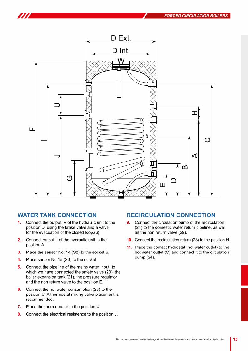
WATER TANK CONNECTION1. Connect the output IV of the hydraulic unit to the
position D, using the brake valve and a valve for the evacuation of the closed loop.(6)
2. Connect output II of the hydraulic unit to the position A.
3. Place the sensor No. 14 (S2) to the socket B.
4. Place sensor No 15 (S3) to the socket I.
5. Connect the pipeline of the mains water input, to which we have connected the safety valve (20), the boiler expansion tank (21), the pressure regulator and the non return valve to the position E.
6. Connect the hot water consumption (26) to the position C. A thermostat mixing valve placement is recommended.
7. Place the thermometer to the position U.
8. Connect the electrical resistence to the position J.
RECIRCULATION CONNECTION 9. Connect the circulation pump of the recirculation
(24) to the domestic water return pipeline, as well as the non return valve (29).
10. Connect the recirculation return (23) to the position H.
11. Place the contact hydrostat (hot water outlet) to the hot water outlet (C) and connect it to the circulation pump (24).
D Ext.
W
FI
JU
G
D Int.
C
AB
H
E D

14 The company preserves the right to change all specifications of the products and their accessories without prior notice
CLOSED LOOP PIPING y All pipes starting from and resulting to collectors must by appropriately insulated in order to resist to temperatures
from -30°C to +120°C. It is also necessary to protect insulating material from UV rays.
y The thickness of insulation depends on the local climate conditions.
y To minimize heat losses, the distance between collectors and the boiler heat exchanger must be the smallest possible.
y Avoid the concentration of air. If this is not possible, the installation of an automatic ventilator at the air accumulation point. concentration is necessary.
y Pipes diameter must be from Ø18mm to Ø22mm for distances up to 20 meters and Ø15mm for distances up to 12 meters.
y All the union nuts must resist compression 6 bar and temperatures from -30°C to +200°C.
y The annual check of the equipment and its connections is mandatory.
POST INSTALLATION INSTRUCTIONS
Before using the system make a final check. Open all the valves and check for any kind of leakage. Repeat the inspection after 30 minutes. Check if the system is filled with water and antifreeze fluid according to the company’s instructions. In case of any failure condition a specialized technician should be called in.
A basic periodic maintenance will assure the long life and high efficiency of the solar installation.
y It is recommended that the appliance is inspected in situ according to the instructions stated in the guarantee twice a year and checked for possible damage (breaking) of the collectors’ glass, leaks in the connecting piping to the mains and to the consumption system, inspection of the pipe insulation and cleaning of the glass.
y If the collectors’ glass is broken, it should be replaced immediately.
y It is recommended that the glass is washed at an hour of low sunlight to avoid damages due to expansion-contraction, due to temperature changes.
y If the fittings are worn (screws, pugs, piping, etc), these should be replaced at the owner’s cost.
y The level of antifreeze in the closed circuit must be checked annually (as it could need toping up), to ensure the efficient operation.
y In cases where there is to be no use of hot water for long periods of time (e.g. during the summer holidays), it is recommended that the collector surface is covered with an opaque cover in order to avoid the building up of high temperatures.
ATTENTION! Place taps with thermostatic regulation up to 38°C for hot water use to prevent burns which may be caused by the high temperature water in the solar installation.

15The company preserves the right to change all specifications of the products and their accessories without prior notice
FORCED CIRCULATION BOILERS
CHECK LIST
INSTRUCTIONS FOR THE INSTALLER
After the installation is complete, the installer, with the help of the check list below has to check all of the points which are noted and mark in the relevant column with a √.
LIST CHECK
COLLECTORS AND EXTERNAL PIPINGIs the installation and the fixing of the support base according to the instructions and local regulations?
Is there an ideal location and facing of the collectors?
Is there humidity inside the collectors?
Are the hydraulic connections of the collectors correct?
Has there been good UV protection on the thermal insulation?
Is the piping properly insulated?
Has the installment on the roof been done according to the local regulations?
HYDRAULIC CONNECTIONSAre there any leaks in the closed circuit, the connections, or in the tube heat exchanger ?
Are the safety valves installed properly?
Does a mixing valve of hot / cold water exist?
ELECTRICAL CONNECTIONIs the electric resistance connected properly? (if it exists)
Has the electric connection been done according to the local regulations? (insulation, grounding, etc...)
GENERALWas the guarantee properly filled in and given to the client?
Were the instructions of use given to the client?
Was the proper selection of the model made according to the needs of the client?
Was the client informed of other options for the production of hot water?
Distributor Data
Full name.....................................................................
Address........................................................................
Telephone.....................................................................
Installer Data
Full name.....................................................................
Address........................................................................
Telephone.....................................................................

V2-
03/1
4
www.orkli.es