formal verification of a gravity-induced loss-of ...home.konkuk.ac.kr/~wnam/pubs/cise14.pdf · 97...
TRANSCRIPT

96 Computing in Science & Engineering 1521-9615/14/$31.00 © 2014 IEEE Copublished by the IEEE CS and the AIP September/October 2014
MOdel CheCking
Formal Verification of a gravity-induced loss-of-Consciousness Monitoring System for Aircraft
Seonmo kim | Department of Computer Science and Engineering, University of Minnesota
Wonhong nam | Department of Internet and Multimedia Engineering, Konkuk University
hyunyoung kil | Research Institute of Computer Information and Communication, Korea University
Myunghwan Park | Republic of Korea Air Force Academy
Gravity-induced loss of consciousness (GLOC) due to blood draining away from the brain is one of the main reasons for many high-gravity maneuvering aircraft accidents, with many pilots losing their lives. This article presents a case study to verify a GLOC monitoring system by using a model-checking technique.
Software is used not only in computer sys-tems but also in various electrical devices. Sometimes, errors in safety critical systems (for example, vehicles, medical instruments,
e-commerce systems, nuclear power plants, and flight control systems) can cost a significant amount of money or threaten human life. However, it’s dif-ficult to ensure that there’s no error in such systems, because these systems generally include complex components that are executed in parallel. In mili-tary-related industry, many high-gravity aircraft have been developed, and they can maneuver be-yond the acceleration tolerance limit of a human being. Unfortunately, for many years, a number of aircraft crashes have occurred due to gravity-induced loss of consciousness (GLOC),1 and many pilots have lost their lives. To prevent these acci-dents, we propose an automatic GLOC monitor-ing system, which we model with the MATRIXx toolkit (see www.ni.com/matrixx). We take a novel approach to formally verify a GLOC monitoring system by using model checking.
Figure 1 illustrates our verification process work-flow. First, we translate the model of the GLOC monitoring system into the input language of the model checker, NuSMV (see http://nusmv.fbk.eu). We then verify the translated model with various safety
properties using NuSMV. During the verification, NuSMV entirely explores the whole state space of the model, to check whether the model satisfies the given property. If the model satisfies the property, NuSMV declares that there’s no violation. Otherwise, NuSMV provides a counter-example that can be used to revise the original model or property. In our case study that verifies the early version of the GLOC system, we found a subtle error that the monitoring system can’t detect. This error is a GLOC situation where a pilot loses consciousness after some intentional movements. To the best of our knowledge, there’s no other work to formally verify a model described in MATRIXx.
MATRiXxMATRIXx, developed at National Instruments, is a platform for control design applications in the aero-space, defense, and automotive industries, as well as academia. For modeling and simulating systems, it provides an interactive graphical framework called SystemBuild. With SystemBuild, developers can drag-and-drop predefined blocks, which are struc-tural elements in MATRIXx; set block parameters; and connect blocks to build systems. For a complex system design, we can compose blocks hierarchically. MATRIXx also provides several tools and functions to analyze and visualize mathematical data, allowing
CISE-16-05-Nam.indd 96 9/15/14 11:56 AM

www.computer.org/cise 97
both debugging and simulation. In addition, the platform contains a customizable, automatic, code-generation tool to generate codes for prototype application and testing on real-time platforms.
Block and SuperBlockBlocks are a basic element to build a model in MATRIXx. Based on the blocks’ functionality, we can divide them into two classes—that is, a basic or a special block. Basic blocks perform dedicated com-putations, whereas special blocks control the execu-tion behavior of other blocks. A block diagram built by a user is called a superblock. Within a superblock, we can place not only general blocks but also another superblock to build a subsystem hierarchically.
Basic BlocksThe MATRIXx language supports a number of basic blocks to model systems. We explain only selected important ones.
■■ ReadVariable. It reads a value of a predeclared variable.
■■ WriteVariable. It writes a value to a predeclared variable.
■■ Gain. It returns the multiplication value of an input value and a scalar gain.
■■ AlgebraicExpression. It returns the value calculated by an arithmetic expression such as Y = U * U, where U and Y denote this block’s input and output, respectively. The expression means that this block returns the square of the input value.
■■ AbsoluteValue. It returns the absolute value of an input.
■■ Sum. It returns the sum of input values.■■ Dot Product. It returns the inner product of
input values.■■ Element Division. It returns the quotient of in-
put values.■■ BlockScript. It includes executable user code
where users can define inputs, outputs, parame-ters, and equations. This code runs in regular line order, and its grammar contains variable types, basic operations, algebraic expressions, and con-ditional expressions such as the if-then-else expression.
Special BlocksThe MATRIXx language supports a number of spe-cial blocks to control execution flow: conditional execution, repetitive execution, termination execution, and execution ordering. We explain only a conditional execution block and an execution ordering block.
■■ IfThenElse. This block type conditionally exe-cutes the inside blocks, depending on the value of a logical expression called an equation.
■■ Sequencer. This block is shown as double vertical lines. It divides a superblock into two areas, and defines the execution order of blocks—that is, all left blocks of a sequencer are executed before all right blocks.
Now let’s look at how we use NuSMV.
nuSMVNuSMV is a computational-tree-logic (CTL) model checker developed as a joint project of the Fondazi-one Bruno Kessler Centre for Scientific and Tech-nological Research (FBK-IRST), Carnegie Mellon University, University of Geneva, and University of Trento. NuSMV is a symbolic model checker based on binary decision diagrams (BDDs),2 and it’s reliably used for the formal verification of industrial designs as well as academic research. Binary decision diagrams are an efficient representation for Boolean functions, by which symbolic model checks can dramatically improve their verification performance. Given a mod-el of the target system and a CTL3 property, NuSMV automatically verifies whether the model satisfies the property. A model-checking tool such as NuSMV uses an exhaustive search of the system’s state space to determine whether a specification is true. In instances with negative results, an error trace is provided and can help users track down where the error occurred.
CTl Model CheckingThe CTL model-checking problem is as follows: given a model K that represents a finite transition system and a CTL formula f expressing some desired specification, automatically check that K satisfies f.4 Now, we formal-ize the models and CTL formula used in this problem.
Figure 1. Verification process workflow. We translate the model of a GLOC monitoring system into NuSMV. We then verify the translated model with various safety properties using NuSMV. During the verification, NuSMV entirely explores the whole state space of the model, to check whether the model satisfies the given property.
MatrixXmodel
NuSMVmodel
Satisfy
Unsatisfywith
counter-example
NuSMV
Feedback
CTLspecification
Translator
CISE-16-05-Nam.indd 97 9/15/14 11:56 AM

98 September/October 2014
Model CheCking
kripke structure. We use a state transition graph called a Kripke structure to represent a finite transi-tion system. To formally define a Kripke structure, let AP be a set of atomic propositions. A Kripke structure over AP is a tuple K = (Q, Q0, T, L) with the following elements:
■■ Q is a finite set of states;■■ Q0 ⊆ Q is the set of initial states;■■ T ⊆ Q × Q is a transition relation that must be
total, that is, for every state q1 ∈ Q, there exists q2 ∈ Q such that (q1, q2) ∈ T; and
■■ L : Q → 2AP is a function mapping each state to a set of atomic propositions that hold in the state.
A path of K is a sequence of states π = q0q1q2 . . . such that q0 ∈ Q0, and for every i ≥ 0, (qi, qi + 1) ∈ T.
Computational tree logic. Temporal logic is a formal-ism to describe sequences of transitions between states in transition system.5 CTL is a propositional, branching-time, temporal logic. Temporal opera-tors (that is, G globally, F sometime in future, X next time, and U until) should immediately follow a path quantifier. The path quantifier can either be an A (for all paths) or an E (for some path). Thus, typical CTL operators are AG f that’s true in a state q if f globally holds at all states along all paths starting from the state q, and EF f that is true in a state q if f eventually holds at some state along some path starting from the state q.
The syntax of CTL formula is as follows:
■■ every atomic proposition p ∈ AP is a CTL for-mula; and
■■ if f and g are CTL formula, then ¬f, f ∧ g, EX f, EG f, and E(f U g) are also CTL formulas.
The remaining operators are considered as be-ing derived from these according to the following rules:
■■ f ∨ g = ¬(¬ f ∧ ¬g),■■ EF f = E(true U f ),■■ AX f = ¬EX(¬ f ),■■ AG f = ¬E(true U ¬ f ),■■ AF f = ¬EG(¬ f ), and■■ A( f U g) = ¬E(¬g U (¬ f ∧ ¬g)) ∧ ¬EG¬g.
Given a Kripke structure K, a state q of K, and a CTL formula f, the notation K, q |= f means that f holds at the state q of K. When the Kripke
structure K is clear from the context, we’ll write simply q |= f. The relation |= is defined induc-tively as follows (assuming that f and g are CTL formula):
■■ q |= p iff p ∈ L(q), where p ∈ AP.■■ q |= ¬f iff q |≠ f.■■ q |= f ∧ g iff q |= f and q |= g.■■ q0 |= EX f iff there exists some path
π = q0 q1 . . . such that q1 |= f.
■■ q0 |= EG f iff there exists some path π = q0 q1 . . . such that qi |= f for every i ≥ 0.
■■ q0 |= E( f U g) iff there exists some path π = q0 q1 . . . such that for some i ≥ 0, qi |= g and for every j < i, qj |= f.
Finally, given a Kripke structure K(Q, Q0, T, L) and a CTL formula f, we say that K satisfies f, denoted as K |= f if for every q ∈ Q0, q |= f.
Syntax and Semantics of nuSMV input languageIn this section, we explain the syntax and seman-tics of some important expressions in the NuSMV language. A NuSMV program consists of a set of modules and there must be one module with the name “main.” Each module includes a set of vari-ables which are declared under the VAR keyword (that is, the variable declaration keyword). To de-termine the value of a variable, there are two ways: using the ASSIGN keyword or using the INIT and TRANS keywords.
The ASSIGN keyword. Under this keyword, a vari-able can be assigned to a numerical value, an ex-pression, or a predeclared variable by using the init, next, or case expression.
■■ init defines the initial value of a variable (for example, init(x) := 0;).
■■ next sets a transition relation by defining the value of a variable in the next state (for example, next(x) := 1;).
■■ case assigns a value (the right hand side of the colon) to a variable when a given guarded con-dition (the left hand side of the colon) is true.
Figure 2 gives a simple example of the ASSIGN keyword.
CISE-16-05-Nam.indd 98 9/15/14 11:56 AM

www.computer.org/cise 99
The INIT keyword. A set of initial values of variables can be assigned by the initial predicate under this keyword (for example, INIT x = 0 & y = 0).
The TRANS keyword. The transition relation can be defined with the next expression under this keyword (for example, TRANS next(x) = 1 & next(y) = 1). By using the INIT and TRANS key-words, the predicates that are equivalent with the ex-ample in Figure 2 can be expressed as Figure 3.
The DEFINE keyword. A symbol can be assigned to a value, an expression, or a predeclared variable under this keyword without the need to declare a variable (for example, DEFINE z := 1;).
glOC Monitoring SystemA GLOC monitoring system is designed to detect if a pilot is in GLOC risk. If the monitoring system determines that the pilot is unconscious, it enables the auto-control system for the safe flight of the air-craft and the alarm signal for the pilot’s conscious recovery, to prevent a possible aircraft disaster. To make a decision, the GLOC monitoring system can observe several physical movements by the pi-lot such as eye blink rate and head slumping. The GLOC monitoring system that this article studies measures the strength of a grip on the control stick in high-gravity maneuvering. The following is the GLOC system algorithm’s steps.
■■ Step 1. If the system detects high-gravity maneu-vering (that is, higher than 4G), the algorithm waits for 7 seconds and proceeds to Step 2.
■■ Step 2. For another 5 seconds, the system monitors pilot movement by measuring the stick-force of the pilot. If the stick-force value becomes greater than a threshold value consec-utively three times, the algorithm goes to Step 3; otherwise, it proceeds to Step 4.
■■ Step 3. If the algorithm determines that the pilot is conscious, and initializes all variables. Then, it returns to Step 1.
■■ Step 4. If the algorithm decides that the pilot is unconscious, it enables the altitude-recovery signal and the alarm signal. These signals enable the auto-control system to place the aircraft in a safe state and help the pilot eventually to wake up. Then, the algorithm goes to Step 5.
■■ Step 5. If the system senses that the pilot recov-ers his consciousness and operates a paddle, these signals become disabled and the system is initial-ized. Then, the algorithm returns to Step 1.
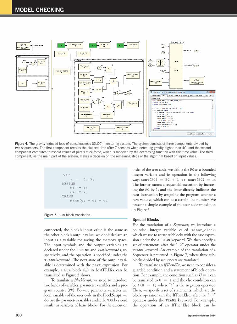
Figure 4 presents the excerption of the GLOC monitoring system, which is modeled in MATRIXx. This system consists of three com-ponents divided by two sequencers. The first component records the elapsed time after 7 seconds when detecting gravity higher than 4G (Step 1), and the second component computes threshold val-ues of pilot’s stick-force, which is modeled by the decreasing function with this time value (Step 2). The third component, as the main part of the system, makes a decision on the remaining steps of the algorithm based on input values. That is, it might activate the monitoring based on the current gravity value, enable the auto-control system and the alarm signal based on the sensed value of pilot’s stick-force, and initialize the system via a specific paddle (Steps 3–5). This whole system operates at 64-Hz frequency.
Translation of MATRiXx Models to nuSMV ModelsIn this section, we propose a formal rule to translate a MATRIXx model to a NuSMV model. This trans-lation is exactly correspondent to the semantics of the MATRIXx language. For the sake of space, we explain only some important parts.
Basic BlocksGiven a basic block, we define input symbols, out-put variables, and block operation where an input symbol denotes a value. Because if two blocks are
MODULE main VAR x : 0..1; y : 0..1; ASSIGN
init(x) := 0; next(x) := case y = 1 : 1; TRUE : x; esac;
Figure 2. The init, next, case, and ASSIGN expression.
INITx = 0
TRANSy = 1 —> next(x) = 1 & !(y = 1) —> next(x) = x
Figure 3. The INIT and TRANS expression.
CISE-16-05-Nam.indd 99 9/15/14 11:56 AM
100 September/October 2014
Model CheCking
connected, the block’s input value is the same as the other block’s output value, we don’t declare an input as a variable for saving the memory space. The input symbols and the output variables are declared under the DEFINE and VAR keywords, re-spectively, and the operation is specified under the TRANS keyword. The next state of the output vari-able is determined with the next expression. For example, a Sum block (⊕) in MATRIXx can be translated as Figure 5 shows.
To translate a BlockScript, we need to introduce two kinds of variables: parameter variables and a pro-gram counter (PC). Because parameter variables are local variables of the user code in the BlockScript, we declare the parameter variables under the VAR keyword similar as variables of basic blocks. For the execution
order of the user code, we define the PC as a bounded integer variable and its operation in the following way: next(PC) = PC + 1 or next(PC) = a. The former means a sequential execution by increas-ing the PC by 1, and the latter directly indicates the next instruction by assigning the program counter a new value a, which can be a certain line number. We present a simple example of the user code translation in Figure 6.
Special BlocksFor the translation of a Sequencer, we introduce a bounded integer variable called minor_clock, which we use to rotate subblocks with the case expres-sion under the ASSIGN keyword. We then specify a set of statements after the “—>” operator under the TRANS keyword. An example of the translation of a Sequencer is presented in Figure 7, where three sub-blocks divided by sequencers are translated.
To translate an IfThenElse, we need to consider a guarded condition and a statement of block opera-tion. For example, the condition such as U = 1 can be translated to U = 1 and the else condition can be !(U = 1) where “!” is the negation operator. Then, we specify a set of statements, which are the block operations in the IfThenElse, after the “—>” operator under the TRANS keyword. For example, the operation of an IfThenElse block can be
Figure 4. The gravity-induced loss-of-consciousness (GLOC) monitoring system. The system consists of three components divided by two sequencers. The first component records the elapsed time after 7 seconds when detecting gravity higher than 4G, and the second component computes threshold values of pilot’s stick-force, which is modeled by the decreasing function with this time value. The third component, as the main part of the system, makes a decision on the remaining steps of the algorithm based on input values.
VAR y : 0..5; DEFINE u1 := 1; u2 := 2; TRANS next(y) = u1 + u2
Figure 5. Sum block translation.
CISE-16-05-Nam.indd 100 9/15/14 11:56 AM

www.computer.org/cise 101
translated as Figure 8. It shows that statement1 is true when U = 1, otherwise statement2 is true.
ConnectionWe also need to translate a connection that’s wired between a block’s outputs and another block’s in-puts. When two blocks are connected, we assign the value of the output variable of the block to the input symbol of another block with “:=” op-erator under the DEFINE keyword—for example, DEFINE sum_u2 := read_variable_y;. This example represents that an output of a ReadVariable block and a second input of a Sum block are connected.
Formal Verification of glOCWe have the presented GLOC monitoring system in the MATRIXx language. To ensure the system’s safety, we verify the GLOC monitoring system by a symbolic model checker, NuSMV. However, because there’s no automatic tool to translate a MATRIXx model to NuSMV input, we proposed the formal translation rule in the previous section. According to the formal rule, we translated the GLOC monitoring system in MATRIXx into the NuSMV input language (around 1,000 lines), which takes several hours. Then, we performed a verification process using NuSMV. Here, we discuss the formal verification of the GLOC moni-toring system.
Verification PropertyIn this case study, we consider four important safety properties. First, the GLOC monitoring sys-tem should enable the two signals when a pilot is in a GLOC state. Second, the monitoring system shouldn’t enable two signals when a pilot is con-scious. Third, the system must not enable two sig-nals when a pilot operates a paddle. Finally, after the system detects high-gravity maneuvering and waits for 7 seconds, it should start monitoring a pilot’s consciousness. These properties are speci-fied by the following four CTL formulas—that is, ϕ1, …, ϕ4:
■■ ϕ1: AG ((ENV_timer = 12 & ENV_ pilot_movement_cnt < 3 ) –> AF(pars_sig_F16 = 1 & gloc_ warning_F16 = 1)).
■■ ϕ2: AG ((ENV_pilot_movement_cnt >= 3 & PC = 0) –>(pars_sig_F16 = 0 & gloc_warning_F16 = 0)).
■■ ϕ3: AG ((ENV_pilot_movement_paddl = 1 & PC = 0) –>(pars_sig_F16 = 0 & gloc_warning_F16 = 0)).
■■ ϕ4: AG ((ENV_timer > 7 & PC = 0 ) –> event_sig = 1).
Verification ResultWe’ve performed the verification of the GLOC monitoring system with the four properties in the previous section. Unfortunately, the result of
x = 0; y = 0; if (x=0) then
y = 1; else
y = 2;
(PC=1 —> next(x)=0 & next(y)=y & next(PC)=PC+1) & (PC=2 —> next(x)=x & next(y)=0 & next(PC)=PC+1) & (PC=3 —> next(x)=x & next(y)=y &
(x=0 —> next(PC)=PC+1) & (!(x=0) —> next(PC)=5)) &(PC=4 —> next(x)=x & next(y)=1 & next(PC)=7) & (PC=5 —> next(x)=x & next(y)=y & next(PC)=PC+1) & (PC=6 —> next(x)=x & next(y)=2 & next(PC)=7)
(a)
(b)
Figure 6. BlockSCript translation: (a) if-then-else BlockScript example, and (b) translated NuSMV code.
ASSIGNinit(minor_clock) := 0;next(minor_clock) := case
minor_clock = 0 : 1;minor_clock = 1 : 2;minor_clock = 2 : 0; TRUE : minor_clock;
esac;TRANS
(next(minor_clock) = 0 -> statement0) & …
Figure 7. Sequencer translation. Three subblocks divided by sequencers are translated.
TRANS (U = 1 —> statement1) & (!(U = 1) —> statement2)
Figure 8. IfThenElse translation. Here, statement1 is true when U = 1,
otherwise statement2 is true.
CISE-16-05-Nam.indd 101 9/15/14 11:56 AM

102 September/October 2014
Model CheCking
ϕ1 turns out to be false, and Figure 9 illustrates a counter-example that NuSMV provides. The counter-example presents an infinite sequence with a loop (that is, a loop from the state 1.256 to the state 1.264) where the pilot loses consciousness but the system doesn’t detect the problem. The error scenario is as follows:
1. The system detects high-gravity maneuvering and waits for 7 seconds.
2. Within 5 seconds, the stick-force value of the pilot becomes greater than a threshold value.
3. The system determines that the pilot is con-scious, and tries to initialize all variables.
4. The system doesn’t initialize all variables due to an if-then-else error, which comes from wrong assignment of a flag variable when the aircraft keeps high-gravity maneuvering.
5. The aircraft still keeps high-gravity maneu-vering, but the system can’t detect it because the system didn’t initialize all variables in the previous step.
6. The pilot is in GLOC state.7. The system doesn’t monitor the pilot.8. The GLOC monitoring system doesn’t enable
the altitude-recovery signal and the alarm signal even though the pilot is unconscious.
The main cause of the error is that there’s a quadruple nested if-then-else block in the
BlockScript where the designer assigns a flag variable continue_flag as 1, by mistake. The setting prevents the monitoring system from be-ing enabled. The previous counter-example that the model checker NuSMV has identified is a subtle error, which isn’t likely to be found by other techniques such as simulation or testing. We reported this problem to the developers of the GLOC monitoring system and the system has been revised—the designer has simplified the quadruple nested if-then-else block and cor-rected the erroneous setting for continue_flag. After the modification, we’ve verified the revised system with four properties, and the revised sys-tem satisfies all the properties with every possible state.
W e see several directions for future work. First, we want to develop an automatic translator
to implement the translation rules from MATRIXx models to NuSMV models, which are proposed in this article. While this work focuses on only the GLOC monitoring system, the whole system needs formal analysis to guarantee its safety. In addition, we plan to study how to verify embedded systems in other modeling languages by using model-checking techniques.
AcknowledgmentsThis research was supported by the Basic Science Research Program through the National Research Foundation of Korea and funded by the Ministry of Science, Information and Communication Technologies (ICT), and Future Planning (2013R1A1A3006204 and 2013R1A1A1005147).
References1. R. Burton, “G-Induced Loss of Consciousness:
Definition, History, Current Status,” Aviation Space and Environmental Medicine, vol. 59, no. 1, 1988, pp. 2–5.
2. R.E. Bryant, “Graph-Based Algorithms for Boolean Function Manipulation,” IEEE Trans. Computers, vol. 35, no. 8, 1986, pp. 677–691.
3. M. Ben-Ari, Z. Manna, and A. Pnueli, “The Temporal Logic of Branching Time,” Acta Informatica, vol. 20, no. 3, 1983, pp. 207–226.
4. E. Clarke, O. Grumberg, and D. Peled, Model Checking, MIT Press, 2000.
5. A. Pnueli, “The Temporal Semantics of Concurrent Programs, Theoretical Computer Science, vol.13, no. 1, 1981, pp. 45–60.
Figure 9. Counter-example for ϕ1 provided by NuSMV. It presents an error scenario where the pilot loses his consciousness but the GLOC monitoring system misses.
CISE-16-05-Nam.indd 102 9/15/14 11:56 AM

www.computer.org/cise 103
Seonmo Kim is a PhD student at the Department of Computer Science and Engineering, University of Min-nesota, Minneapolis. His research interests include for-mal methods, formal verification, and model checking. Kim has a BS in engineering from Konkuk University, Seoul, Korea. Contact him at [email protected].
Wonhong Nam (the corresponding author) is an asso-ciate professor at the Department of Internet and Multi-media Engineering, Konkuk University, Seoul, Korea. His research interests include formal methods, formal verifi-cation, model checking, automated planning, and Web services composition. Nam has a PhD in computer and information science from the University of Pennsylva-nia, Philadelphia. Contact him at [email protected].
Hyunyoung Kil is a postdoctoral researcher at the Re-search Institute of Computer Information and Commu-nication, Korea University, Seoul. Her research interests include automated planning, Web services composition,
service-oriented architectures, and Web sciences. Kil has a PhD in computer science and engineering from the Pennsylvania State University, State College. Contact her at [email protected].
Myunghwan Park is an assistant professor at the De-partment of Computer Science and Electrical Engineer-ing, Republic of Korea Air Force Academy, Cheongju, Korea. His research interests include testing method-ologies, verification, and validation of safety critical systems, modeling, and simulation. Park has a PhD in computer science from the University of Minnesota, Minneapolis. Contact him at [email protected].
Selected articles and columns from IEEE Computer Society publications are also available for free at
http://ComputingNow.computer.org.
NewslettersStay Informed on Hot Topics
computer.org/newsletters
CISE-16-05-Nam.indd 103 9/15/14 11:56 AM