fouling control in ceramic nanofiltration membranes during
TRANSCRIPT
Delft University of Technology
Fouling control in ceramic nanofiltration membranes during municipal sewage treatment
Kramer, F. C.; Shang, R.; Rietveld, L. C.; Heijman, Sebastiaan
DOI10.1016/j.seppur.2019.116373Publication date2020Document VersionFinal published versionPublished inSeparation and Purification Technology
Citation (APA)Kramer, F. C., Shang, R., Rietveld, L. C., & Heijman, S. (2020). Fouling control in ceramic nanofiltrationmembranes during municipal sewage treatment. Separation and Purification Technology, 237, [116373].https://doi.org/10.1016/j.seppur.2019.116373
Important noteTo cite this publication, please use the final published version (if applicable).Please check the document version above.
CopyrightOther than for strictly personal use, it is not permitted to download, forward or distribute the text or part of it, without the consentof the author(s) and/or copyright holder(s), unless the work is under an open content license such as Creative Commons.
Takedown policyPlease contact us and provide details if you believe this document breaches copyrights.We will remove access to the work immediately and investigate your claim.
This work is downloaded from Delft University of Technology.For technical reasons the number of authors shown on this cover page is limited to a maximum of 10.
Green Open Access added to TU Delft Institutional Repository
‘You share, we take care!’ – Taverne project
https://www.openaccess.nl/en/you-share-we-take-care
Otherwise as indicated in the copyright section: the publisher is the copyright holder of this work and the author uses the Dutch legislation to make this work public.

Contents lists available at ScienceDirect
Separation and Purification Technology
journal homepage: www.elsevier.com/locate/seppur
Fouling control in ceramic nanofiltration membranes during municipalsewage treatment
F.C. Kramer⁎, R. Shang, L.C. Rietveld, S.J.G. HeijmanDepartment of Sanitary Engineering, Faculty of Civil Engineering and Geosciences, Delft University of Technology, P.O. Box 5048, 2600 GA Delft, the Netherlands
A R T I C L E I N F O
Keywords:Ceramic nanofiltrationFouling controlMunicipal sewageReaction based precoatForward flush
A B S T R A C T
Using ceramic nanofiltration membranes for treatment of municipal sewage is upcoming. However, theknowledge on fouling control methods for this application are very limited. The most commonly used foulingcontrol method, chemical cleaning, has disadvantages. Chemical cleaning negatively impacts (i) the glass seallayer of tubular ceramic nanofiltration membranes and (ii) the environment, especially when using sodiumhypochlorite for removal of organic fouling. Therefore, the use of chemical cleaning should be limited as muchas possible. In this research, first, the well-known fouling control methods for polymeric micro- and ultra-filtration membranes, were studied on ceramic nanofiltration membranes: hydraulic backwash and forwardflush. Second, a precoat method was combined with a chemical reaction to aid the detachment of the formedcake layer. In this method, a precoat layer was filtered atop of the membrane surface before the start of filtration.The precoat layer then acts as a barrier between the foulants and the membrane surface. After filtration, theprecoat layer reacts with the cleaning reagent underneath the fouling layer to enable fast removal of fouling.Results showed that hydraulic backwash was not effective to be used for this type of membranes. Forward flushwas able to maintain a higher flux but the relative production downtime was high. Reaction based precoat wasmost effective in maintaining a high flux and resulted in the highest net water production. Two reaction basedprecoat methods were tested of which the reaction of calcium carbonate with citric acid was more effective thana Fenton reaction.
1. Introduction
Worldwide water scarcity creates a need for different water sourcessuch as municipal sewage [1–3]. Since two decades, the interest forceramic nanofiltration (NF) has emerged for this purpose. Severalcharacteristics make ceramic membranes suitable for municipalsewage: its resistance to high temperatures, pressures, and concentra-tions of chemicals [4–7]. Furthermore, ceramic NF membranes are lesssusceptible to organic fouling than polymeric NF [8,9].
One of the largest challenges of using membranes for treatment ofmunicipal sewage is controlling fouling on the membrane surface inorder to produce as much water as possible. The two most importantperformance indicators for fouling control strategies are: (i) keeping thefiltration downtime as low as possible and (ii) maintaining a high fluxduring filtration. Both of these aspects contribute to a higher waterproduction.
Fouling can be divided into two main categories: reversible andirreversible fouling. Reversible fouling is defined as fouling that settlesatop the membranes surface and can, therefore, easily be removed with
various fouling control methods. Whereas, irreversible fouling is foulingthat blocks the pores of the membrane. The irreversible fouling isusually strongly attached to the pore which makes it difficult to removethis fouling. Irreversible fouling can only be removed by chemicalcleaning.
The most common cleaning method used for ceramic membranefiltration is by chemicals which removes the reversible and irreversiblefouling [4,10–13]. Depending on the type of fouling, sodium hypo-chlorite, acid solutions, and/or base solutions are the most commonlyused chemicals to clean the membranes. Chemical cleaning is effectivefor the removal of (ir)reversible fouling. However, when only applyingchemical cleaning the permeability is, on average, low during the fil-tration cycle; resulting in a low water production. Moreover, from asustainability point of view fouling control methods with a lower che-mical consumption are preferred. Previous research showed that longterm use of chemical cleaning, such as sodium hypochlorite, damagesthe glass seal layer at the edges of tubular ceramic NF membranes [14].Therefore, chemical treatment using sodium hypochlorite should beavoided.
https://doi.org/10.1016/j.seppur.2019.116373Received 5 April 2019; Received in revised form 30 November 2019; Accepted 1 December 2019
⁎ Corresponding author.E-mail address: [email protected] (F.C. Kramer).
Separation and Purification Technology 237 (2020) 116373
Available online 03 December 20191383-5866/ © 2019 Elsevier B.V. All rights reserved.
T
In literature, research on alternative fouling control method usingceramic and polymeric NF is limitedly available. Especially since alimited amount of papers describing sewage treatment using ceramic orpolymeric NF. Sayed et al. reported that using polymeric NF for thetreatment of municipal sewage was not feasible when using chemicalcleaning as fouling control method due to the extensive downtime re-quired [15]. However, for polymeric ultrafiltration (UF) and micro-filtration (MF). Backwash and forward flush are the most commonlyused methods for polymeric UF and MF to remove hydraulic reversiblefouling [16]. Applying hydraulic backwash or forward flush has thebenefit of keeping the permeability higher compared to regular filtra-tion. The advantage of forward flush over backwash is that feed watercan be used to flush the membrane without produced water loss whichresults in a higher net water production. Much variation in backwashand forward flush methods can be found for polymeric UF and MF, e.g.using a combination of backwash and forward flush, cross-flushing withpressure pulsing [17], air-enhanced backwashing [18,19]. The filtra-tion layer of polymeric NF membranes is thin and fragile which makesthem not suitable for these methods. However, these methods couldhave potential for removal of organic fouling during ceramic NF, sincethese membranes are more robust.
Ghadimkhani et al. reported that defouling of ceramic UF flat sheetmembranes by air Nano Bubbles holds potential as an innovative sus-tainable technology [20]. Fujioka et al. used ozonated water flushing asfouling control method using ceramic NF membranes during secondarywastewater effluent treatment [21]. They found that the progression offouling was limited to 35% in transmembrane pressure increase overfive filtration cycles [20]. However, application of ozone is energy in-tensive and the by-products need to be treated with consideration.
The most recent development in the field of membrane developmentare carbon nanotube (CNT) based composite membranes. These mem-branes offer enhanced membrane properties such as lower fouling po-tential than polymeric or ceramic membranes [22]. Fan et al. [2016]developed a superhydrophobic CNT hollow fibre membrane and foundthat when using electrochemical assistance lower fouling potential oc-curred: the flux remained high during treatment of natural organicmatter contain water for 36 h of operation [23,24]. However, thesemembranes need to be developed further before they can be applied forwater treatment, e.g. the potential toxicological effect of CNT in theenvironment is not studied yet [22].
Another fouling control method found in literature is enhancedprecoat engineering (EPCE®) used for polymeric UF and MF [25,26]. Inthis method, a suspension is dosed on the membrane (the precoat layer)to form an easily removable and permeable layer on the membrane.During filtration the fouling attaches or adsorbs onto the precoat layerinstead of on the membrane. When the threshold pressure is reached,the membrane will be hydraulic backwashed. Then, during backwashthe cake layer detaches easily from the membrane [25,26]. Alter-natively, precoating using coagulants has been used to enable UFmembranes to remove natural organic matter [27]. These methods havenot been tested on ceramic NF membranes so far.
Therefore, several fouling control protocols were studied to controlfouling in ceramic NF membranes, filtering high municipal sewage.First, several commonly known methods for polymeric UF membraneswere tested on ceramic NF membranes: hydraulic backwash and for-ward flush. Second, a reaction based precoat was tested, where a pre-coat was filtered on the surface layer of the membrane. Then, afterregular filtration, a chemical was dosed to initiate a chemical reactionto enhance the detachment of the cake layer, followed by a forwardflush. Both the Fenton reaction and a calcium carbonate reaction withacid were used, where iron(III) chloride flocs and calcium carbonateparticles were used as precoat.
The experiments were realised under lab conditions using the modelcompound sodium alginate to mimic fouling on the membranes.Sodium alginate is commonly used as a surrogate for extracellularpolymeric substance (EPS) which is one of the largest contributors to
fouling in organic loaded waste streams [28–34].
2. Materials & methods
2.1. Membranes
Filtration experiments were performed using ceramic NF mem-branes with a filtration layer of titanium oxide, a molecular weight cut-off (MWCO), as indicated by the manufacturer, of 450 Da, a mean poresize of 0.9 nm, and an open porosity of 30–40%. The actual MWCO wasmeasured regularly, the results follow later in this paper. These ceramicNF membranes have a negative surface charge. Previous researchshowed that the zeta potential of the membranes was negative, −8 to−22 mV for pH 4–9, respectively [35].
Two different membrane configurations were used; consisting of (i)four large membranes in a tandem, and (ii) one small membrane. First,the hydraulic backwash experiments were executed with the largemembranes. However, these membranes were damaged during the tests(described in Section 3.1), and could not be used for further studies.Therefore, the alternative membrane configuration, with smallermembranes, was used for the other experiments. The large membraneconsisted of a 19 channel tube with a length of 1200 mm and an ef-fective membrane area of 0.25 m2. The small membrane has a single-channel, tubular configuration with a length of 100 mm and an effec-tive filtration area of 0.163 dm2 (Inopor GmbH, Germany).
2.2. Filtration setup
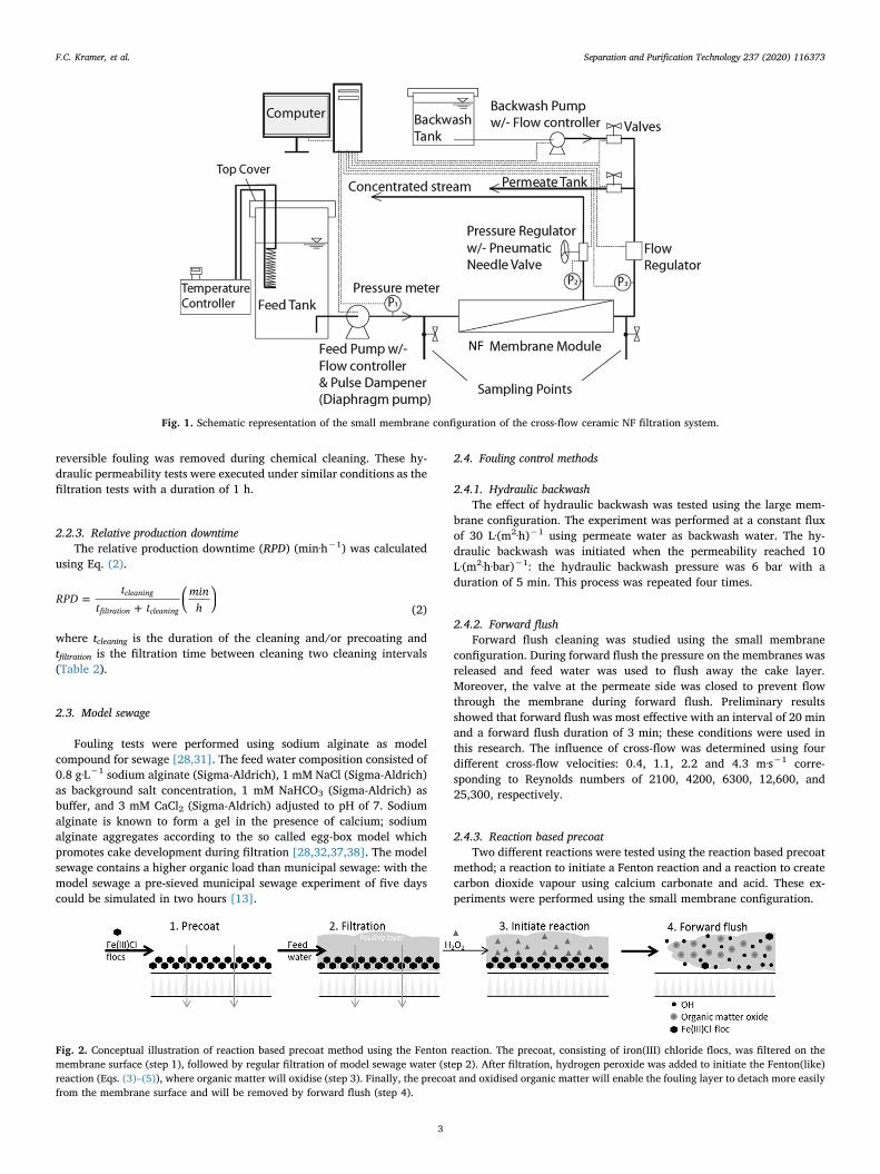
Ceramic NF membranes experiments were performed with a cross-flow filtration system using a pneumatic diaphragm pump (Hydra-cell)with a pulsation dampener. The feed water was recirculated; both thepermeate and the concentrate were fed back into the feed tank, exceptfor the sampling volume which was a negligible amount (< 0.1%)(Fig. 1). In order to ensure that the feed water quality remained con-stant during the experiment, feed water samples were analysed reg-ularly.
The experiments using small and large membrane configurationswere conducted with slightly different conditions at room temperature.When using the small configuration, the single pass water recoverywas< 1% and the flux was 50–60 L·(m2·h)−1, unless otherwise speci-fied, and a cross-flow velocity of 1.0–1.2 m·s−1 (Fig. 1). In the experi-ments using the configuration with the large membrane, a recirculationpump was added to the setup to reach a cross-flow velocity of1.0–1.2 m·s−1. The flux of these membranes was between 15 and 40L·(m2·h)−1, unless otherwise specified, and the water recovery 50%.The experiments with both configurations were conducted at a trans-membrane pressure (TMP) of 4.5–5.5 bar. All experiments were exe-cuted at least twice to ensure repeatability of the results. An experimentwas considered as repeatable when the standard deviation between theresults was less than 5%.
2.2.1. Temperature correction of permeabilityIn order to correct for the temperature, the following equation (Eq.
(1)) was used to calculate the permeability of the membrane:
=− −
°L J eP
·9ΔC
T
20
0.0239·( 20)
(1)
where L20 °C is the temperature-corrected permeability at 20 °C(L·(m2·h·bar)−1), T is temperature of water (°C), J is membrane flux(L·(m2·h)−1), and ΔP is transmembrane pressure (bar). All permeabilityvalues were temperature-corrected to 20 °C [36].
2.2.2. Hydraulic permeability of clean membranesA demineralised water filtration test was performed after chemical
cleaning and before each filtration experiment to determine the hy-draulic permeability. The hydraulic permeability indicates if the (ir)
F.C. Kramer, et al. Separation and Purification Technology 237 (2020) 116373
2
reversible fouling was removed during chemical cleaning. These hy-draulic permeability tests were executed under similar conditions as thefiltration tests with a duration of 1 h.
2.2.3. Relative production downtimeThe relative production downtime (RPD) (min·h−1) was calculated
using Eq. (2).
=+
⎛⎝
⎞⎠
RPDt
t tmin
hcleaning
filtration cleaning (2)
where tcleaning is the duration of the cleaning and/or precoating andtfiltration is the filtration time between cleaning two cleaning intervals(Table 2).
2.3. Model sewage
Fouling tests were performed using sodium alginate as modelcompound for sewage [28,31]. The feed water composition consisted of0.8 g·L−1 sodium alginate (Sigma-Aldrich), 1 mM NaCl (Sigma-Aldrich)as background salt concentration, 1 mM NaHCO3 (Sigma-Aldrich) asbuffer, and 3 mM CaCl2 (Sigma-Aldrich) adjusted to pH of 7. Sodiumalginate is known to form a gel in the presence of calcium; sodiumalginate aggregates according to the so called egg-box model whichpromotes cake development during filtration [28,32,37,38]. The modelsewage contains a higher organic load than municipal sewage: with themodel sewage a pre-sieved municipal sewage experiment of five dayscould be simulated in two hours [13].
2.4. Fouling control methods
2.4.1. Hydraulic backwashThe effect of hydraulic backwash was tested using the large mem-
brane configuration. The experiment was performed at a constant fluxof 30 L·(m2·h)−1 using permeate water as backwash water. The hy-draulic backwash was initiated when the permeability reached 10L·(m2·h·bar)−1: the hydraulic backwash pressure was 6 bar with aduration of 5 min. This process was repeated four times.
2.4.2. Forward flushForward flush cleaning was studied using the small membrane
configuration. During forward flush the pressure on the membranes wasreleased and feed water was used to flush away the cake layer.Moreover, the valve at the permeate side was closed to prevent flowthrough the membrane during forward flush. Preliminary resultsshowed that forward flush was most effective with an interval of 20 minand a forward flush duration of 3 min; these conditions were used inthis research. The influence of cross-flow was determined using fourdifferent cross-flow velocities: 0.4, 1.1, 2.2 and 4.3 m·s−1 corre-sponding to Reynolds numbers of 2100, 4200, 6300, 12,600, and25,300, respectively.
2.4.3. Reaction based precoatTwo different reactions were tested using the reaction based precoat
method; a reaction to initiate a Fenton reaction and a reaction to createcarbon dioxide vapour using calcium carbonate and acid. These ex-periments were performed using the small membrane configuration.
Fig. 1. Schematic representation of the small membrane configuration of the cross-flow ceramic NF filtration system.
Fig. 2. Conceptual illustration of reaction based precoat method using the Fenton reaction. The precoat, consisting of iron(III) chloride flocs, was filtered on themembrane surface (step 1), followed by regular filtration of model sewage water (step 2). After filtration, hydrogen peroxide was added to initiate the Fenton(like)reaction (Eqs. (3)–(5)), where organic matter will oxidise (step 3). Finally, the precoat and oxidised organic matter will enable the fouling layer to detach more easilyfrom the membrane surface and will be removed by forward flush (step 4).
F.C. Kramer, et al. Separation and Purification Technology 237 (2020) 116373
3

2.4.3.1. Reaction based precoat using a Fenton reaction. Iron(III) chlorideflocs were used as precoat, after filtration hydrogen peroxide was dosedto initiate the Fenton reaction (see Fig. 2). In a Fenton reaction ironworks as a catalyst for hydrogen peroxide, resulting in an advancedoxidation reaction. Free radicals are formed being able to degradeorganic matter (OM). Both iron forms, iron(II) and iron(III), react withhydrogen peroxide which are known as a Fenton (Eqs. (4) and (5)) anda Fenton-like reaction (Eqs. (3) and (5)) [39,40].
Fe3+ + H2O2 → Fe2+ + HOO% + H+ (3)
Fe2+ + H2O2 → Fe3+ + HO% + OH− (4)
HO% + OM → OMoxid (5)
Iron(III) chloride 41% solution (Merck) was used for the precoatingsuspension. Iron(III) chloride was diluted in demineralised water to therequired concentration. Various concentrations were tested: 40, 420,2100, and 4200 mg·L−1. Moreover, the pH was adjusted to 5, 7, and 8to determine the most effective pH, since it affects iron floc sizes [41].
The precoating suspension was filtered on a clean ceramic NFmembrane at laminar flow conditions with a cross-flow velocity of0.4 m·s−1 at 5 bar with a duration of 10 min. Then, a fouling test wasdone using model sewage for 40 min as described before. Next, a hy-drogen peroxide solution was dosed for 1, 5, or 10 min with a pH ofaround 2.5, since this is the optimal pH to initiate a Fenton or Fenton-like reaction [25]. Only iron(III) was dosed, however, iron(III) convertsinto iron(II) in the presence of hydrogen peroxide (Eq. (3)). Thus,during dosage of hydrogen peroxide, both iron(II) and Iron(III) werepresent on the membrane surface resulting in a Fenton and a Fenton-like reaction. Finally, forward flush was executed at a cross-flow velo-city of 1.1 m·s−1 for 5 min without pressure using feed water to removethe loosened cake layer (see Fig. 2). This procedure of precoating andhydrogen peroxide dosing was repeated three times.
The amount of iron which deposited on the membrane surfaceduring precoating was measured and analysed using a mass balance.The iron concentration of the feed, concentrate, and permeate streamwas analysed using the total iron test cell test using the NOVA 60Spectroquant® (Merck) (Table 1).
2.4.3.2. Reaction based precoat using calcium carbonateparticles. Calcium carbonate particles were used as precoat, afterfiltration two kinds of acids were dosed to initiate the reactionbetween calcium carbonate and acid forming calcium carbonatebubbles (Fig. 3). For the reaction based precoat using calciumcarbonate two different acids were tested to initiate carbon dioxiderelease: hydrochloric acid (Eq. (6)) or citric acid (Eqs. (7) and (8)).
+ → + +CaCO aq HCl aq CaCl aq H O aq CO g( ) 2 ( ) ( ) ( ) ( )3 2 2 2 (6)
+ → + ++ −CaCO C H O Ca C H O H CO3 2 ( ) 6 33 6 8 7 3 6 5 7 2 3 (7)
→ +H CO aq H O aq CO g( ) ( ) ( )2 3 2 2 (8)
A calcium carbonate suspension used for precoating was preparedfrom CaCO3 powder (Merck). The powder was carefully mixed withwater in a concentration of 100, 200, or 400 mg·L−1 to make a colloid
suspension. To avoid dissolution of Ca2+ and CO32− the suspension was
kept at a pH of 10, and to ensure uniformly distributed CaCO3 nano-particles, the suspension was sonicated at 40% amplitude for threehours [42]. Then, the suspension was filtrated over the clean mem-branes for 10 min to create a precoat layer. After filtration with modelsewage, the membrane was cleaned using citric acid or hydrochloricacid in a concentration of 400 mg·L−1 for a duration of 1, 5, or 15 min(see Fig. 3). This procedure of precoating and acid dosing was repeatedthree times.
The amount of calcium which was deposited on the membranesurface during precoating was measured and analysed using a massbalance. The calcium concentration of the feed, concentrate, andpermeate stream was analysed using the calcium test cell test using theNOVA 60 Spectroquant® (Merck) (Table 1).
2.4.4. Chemical cleaningAfter each experiment, the membranes were chemically cleaned to
remove all fouling. The chemical cleaning was carried out by soakingthe membranes in a 0.1% sodium hypochlorite solution for 1 h.
2.5. MWCO analysis
The MWCO of the ceramic NF membranes were measured beforeand after each experiment to monitor the quality of the membranes.Tam & Tremblay (1991) described a method to calculate the MWCO;this method is widely used for the determination of the pore size dis-tribution of polymeric and ceramic membranes [43–47]. The MWCOwas investigated by filtering a mixture of five different polyethyleneglycol (PEG) molecules (200, 300, 400, 600, and 1000 Da) (Sigma-Al-drich) each in a concentration of 6 mg·L−1. The same settings were usedduring filtration as described for the hydraulic permeability.
The feed and permeate samples were analysed using HPLC(Shimadzu) equipped with size exclusion chromatography columns(SEC, 5 μm 30 Å PSS SUPREMA) and a RID-20A refractive index de-tector. The carrier liquid in the HPLC was ultrapure water at a flow rateof 1 mL·min−1. From the HPLC analyses, the molecular weight dis-tribution curves of the dissolved PEG molecules in the feed andpermeate were derived. These were transformed into retention curvesby calculating the rejection percentage of a PEG with a certain mole-cular weight (Ri) using Eq. (4):
⎜ ⎟= ⎛⎝
− ⎞⎠
Rc c
c(%) ·100%i
i feed i permeate
i feed
, ,
, (9)
where ci, feed is the PEG concentration in the feed samples and ci, permeate
in the permeate samples. Afterwards, the experimental retention curveswere described by a log-normal model as function of molecular weight(MW) and MWCO using Eq. (5) [44,45,48]. Eq. (5) was used to modelretention curve to be able to calculate the MWCO.
∫=
⎡⎣⎢
− − + ⎤⎦⎥
σ MW
s π MW
exp MW MWCO ss
dMW
( )1
2· 1 ·
(ln( ) ln( ) 0.56· )2·
·
sMW
MW
MW
MW
0
2
2
s
(10)
where σ(MWs) is the reflection coefficient for a PEG with a molecularweight MWs, sMW is the standard deviation of the molecular weightdistribution.
In this method, the separation of the PEG molecules is assumed to beonly based on size exclusion with negligible solute diffusion. Therefore,the molecular size of the PEG solutes (ds in nm) is correlated to theirmolecular weight (MW in Da) as shown in Eq. (6) [44,48].
=d MW0.065·s0.438 (11)
Finally, the MWCO was estimated at 90% of the retention curve[36,45].
Table 1Deposition of iron membrane surface during precoating derived from massbalance.
Precoating suspension,concentration ironchloride
Net Irondeposited
Precoatingsuspension,concentration CaCO3
Net calciumdeposited
40 mg·L−1 0.2 mg 100 mg·L−1 104 mg420 mg·L−1 97 mg 200 mg·L−1 239 mg2100 mg·L−1 406 mg 400 mg·L−1 801 mg4200 mg·L−1 626 mg
F.C. Kramer, et al. Separation and Purification Technology 237 (2020) 116373
4

3. Results & discussion
3.1. Hydraulic backwash
First, the MWCO of the four large membranes was determined toensure the right quality of the membranes. Then, the effect of hydraulicbackwash was studied by comparing it with the permeability of themembrane and without cleaning. In the experiment without hydraulicbackwash the permeability decreased from 22 to 4.5 L·(m2·h·bar)−1
within two hours (Fig. 4a). After hydraulic backwash was applied, anincrease in permeability was shown; 43, 37, 31, and 25%, respectively,resulting in a higher permeability than without cleaning and thuspostponing the chemical cleaning. However, the performed hydraulicbackwash had a high relative production downtime (Table 2).
Afterwards, the effect of hydraulic backwash on the filtration layerswas analysed by determining the MWCO of the membranes. The resultsshowed that the MWCO of the membranes after the hydraulic backwashexperiments was too high to measure. Therefore it was concluded thatthe ceramic NF membranes were damaged during the backwash op-eration. After opening the membrane modules, the damage on the edgesof the membranes was clearly visible; resulting in the transport of feedwater to the permeate via the support layer of the membranes (Fig. 4b).The experiments were repeated at lower pressures of 1 and 2 bar.However, this did not affect the permeability compared to the perme-ability without cleaning; apparently the cleaning back flux or hydraulicsheer force was too low to have an effect. This is in line with the findingof Chang et al. (2017) who studied hydraulic backwash parameters of
polymeric membranes treating surface water [49]. They found that thehydraulic backwash strength should be 2.1 times the filtration flow. Thebackwash strength was expressed as the ratio between the backwashflux to permeate flux under constant flux, or the ratio of backwashpressure to operating pressure under constant pressure. In our case, at apressure of 1 and 2 bar, a backwash strength of 2.1 was not reached.
3.2. Forward flush cleaning
First, the MWCO of the small membranes, used for these experi-ments, were measured to be between 602 and 649 Da. The MWCOremained constant for the whole duration of this study. Next, intervalforward flush cleaning was studied using feed water at 20 min intervals,since these intervals were found to be the most effective in removingreversible fouling (results not shown). Various cross-flow velocities,ranging from 0.4 to 4.3 m·s−1, during forward flush were compared. Ata cross-flow velocity of 0.4 m·s−1 the flow was laminar and at highercross-flow velocities the flow was turbulent. The fouling experimentwas performed with a cross-flow velocity of 1.1 m·s−1. The results in-dicate that the effect of the forward flush was similar for all cross-flowvelocities (Fig. 5a). This is in contrast with results obtained withpolymeric UF, where forward flush is commonly applied, and wherehigher forward flush cross-flow velocities have resulted in higherfouling removals [16,19,50]. This could be explained by the weak at-tachment of the fouling layer on the ceramic NF membrane surface thanpolymeric NF membrane surface [8,9] which makes a low cross-flowsufficient to remove organic fouling. Moreover, similar results were
Fig. 3. Conceptual illustration of reaction based precoat method using the calcium carbonate particles. The precoat consisting of calcium carbonate particles wasfiltered on the membrane surface (step 1), followed by regular filtration of model sewage water (step 2). After filtration, citric acid was added to initiate the reactionbetween calcium carbonate and citric acid forming calcium carbonate bubbles (Eqs. (6)–(8)) (step 3). Finally, the precoat and calcium carbonate bubbles will enablethe fouling layer to detach more easily from the membrane surface and will be removed by forward flush (step 4).
Fig. 4. (a) Permeability in time during ceramic NF using model sewage with and without interval hydraulic backwash performed with the configuration with largemembranes. Hydraulic backwash was applied at 6 bar pressure for 5 min when the permeability had reached 10 L·(m2·h·bar)−1. (b) Pictures of damage of the ceramicNF membranes after hydraulic backwash was applied. The layer on the edges of the membrane were damaged. Therefore, the feed water can flow directly to thepermeate via the support layer of the membrane.
F.C. Kramer, et al. Separation and Purification Technology 237 (2020) 116373
5

reported by Fujioka et al. using similar ceramic NF membranes whileapplying forward flush with clean water [21].
The decrease in permeability – meaning the accumulation of fouling– reduced with each forward flush cycle until a steady state was reached(Fig. 5b). The impact of the forward flush (the hydraulic removal) thusincreased with each cycle, and fouling became more reversible. Thiscan be explained by the fact that irreversible fouling stabilises in time[51].
3.3. Reaction based precoat
3.3.1. Reaction based precoat using a Fenton-reactionIn order to test the effectiveness of a Fenton (like) reaction, two
preliminary tests were executed. Firstly, the fouling curve of a mem-brane with a precoat layer was compared with a fouling curve of a cleanmembrane; the shape of the curve was more or less similar and bothcurves ended at the same value after 130 min (Fig. 6a). Secondly, theeffect of hydrogen peroxide dosing was tested on both the untreatedand the precoated membranes. The permeability of the uncoatedmembrane increased with 8% after the first hydrogen peroxidecleaning, while the precoated membranes showed an increase of about75% in permeability (Fig. 6b) which is a clear indication of the oc-currence of Fenton (like) reactions.
Next, several experiments were executed to optimise the Fentonreactions. Firstly, the feed suspension, used for the precoating, of ironchloride was prepared at pH 5, 7, and 8 which affects the size andstrength of the iron flocs [41]. The deposition of the flocs on themembrane surface was influenced by the size and strength of the flocsand, thus, determines the stability of the precoat layer [25]. The highestrecovery was obtained when the reaction was realised at a pH of 7(Fig. 6c). Thus, the deposition of the flocs was most stable with a feedsuspension of pH 7. Secondly, the concentration of iron chloride in thefeed suspension, used for precoating, was optimised. When comparing
feed concentrations of 42, 420, 2100, and 4200 mg·L−1 iron chloride,the concentration of 420 and 4200 mg·L−1 iron chloride performed thebest (Fig. 6d). When precoating with a feed concentration of420 mg·L−1 iron chloride, net 97 mg iron deposited on the membranesurface (Table 1). The rest of the suspension could be reused.
After the first reaction based precoat, the method was repeated asecond time including precoating and hydrogen peroxide treatment.Since not all fouling was removed, probably the precoat was not de-posited on the membrane surface itself, but on the fouling layer on themembrane surface. The results therefore showed that the secondcleaning was less effective than the first cleaning (Fig. 6b-d). The in-crease in irreversible fouling was probably caused by the fact that theprecoat layer was not evenly distributed on the membrane surface dueto the presence of fouling on the membrane surface. Galjaard et al.(2001) also saw an increase in irreversible fouling after the first cyclebecause the membrane surface was not entirely covered with the dosedprecoat material [25]. Causing the non-protected layer to foul and notbeing restored after hydraulic backwash.
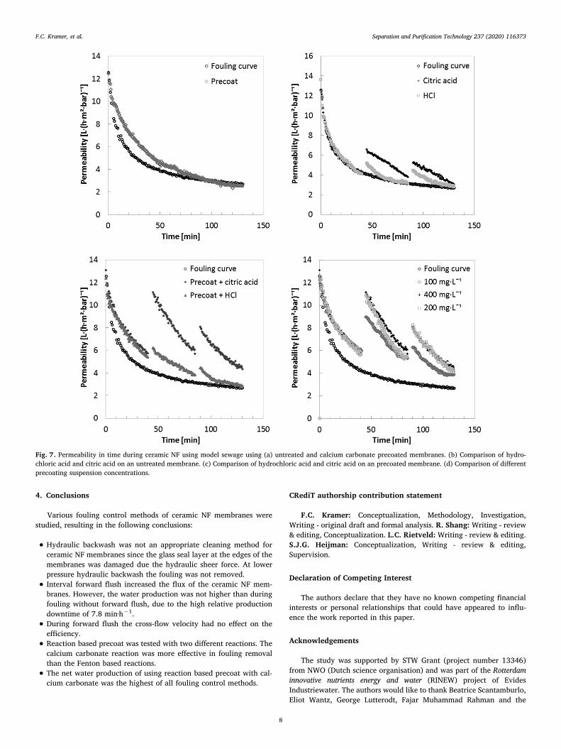
3.3.2. Reaction based precoat using calcium carbonateThe effectiveness of a calcium carbonate reaction with acid was
studied with a series of preliminary tests. Firstly, the fouling curves ofan untreated and a precoated membrane were compared; the perme-ability drop of the precoated membrane in comparison with the un-coated membrane was slower but after 130 min the curves were at thesame permeability value (Fig. 7a). Secondly, the effect of an acidcleaning, using either citric acid or HCl, on the permeability of an un-treated fouled membrane was studied. The citric acid cleaning of theuntreated membrane resulted in a permeability increase of 27%,whereas HCl was less effective with 11% permeability increase(Fig. 7b). Thirdly, the fouled precoated membranes were cleaned withHCl, causing an increase of 12% in permeability (Fig. 7c). However, theeffect was much greater when cleaning the fouled precoated
Table 2Summary of the cleaning protocol of different fouling control methods.
Cleaning method Membrane configuration Cleaning interval (min) Cleaning time (min) Precoat time (min) Relative production downtime (min·h−1)
Forward flush Small 20 3 NA 7.8Reaction based precoat: Fenton Small 40 1 10 16.1Reaction based precoat: CaCO3 Small 40 1 10 16.1
Fig. 5. (a) Permeability in time during ceramic NF using model sewage with and without interval forward flush (20 min). Different cross-flow velocities duringforward flush were compared, ranging from 0.5 to 4.3 m·s−1. (b)Fouling and hydraulic removal per forward flush cycle. Forward flush cycles of 20 min wereexecuted.
F.C. Kramer, et al. Separation and Purification Technology 237 (2020) 116373
6

membranes with citric acid: 76% permeability increase. This is prob-ably due to the fact that citric acid is a weak acid whereas HCl is anstrong acid. During the reaction of HCl with calcium carbonate, H+ wasconverted which causes a pH increase which limits the reaction (Eq.(6)). However, the reaction of citric acid with calcium carbonate worksdoes not affect the pH and keeps going (Eqs. (7) and (8)). Therefore,citric acid is probably more effective.
Then, the concentration of calcium carbonate in the feed suspen-sion, used for precoating, was optimised. When comparing a feedconcentration of 100, 200, and 400 mg·L−1 calcium carbonate, theconcentration of 200 and 400 mg·L−1 calcium carbonate showed thehighest permeability recovery after cleaning (Fig. 7d). This relates to adeposition of 239 and 801 mg calcium carbonate on the membranesurface during precoating (Table 1).
Again, the second cleaning of the reaction based precoat was lesseffective in permeability increase than the first one (Fig. 7c-d). Prob-ably, a calcium carbonate deposition was less stable during the secondinterval, since not all fouling was removed during the first interval,similar results were observed by the reaction based precoat using theFenton reaction (Fig. 6a–d).
3.4. Net water production
To compare the various fouling control methods, the net waterproduction was calculated for all experiments and compared to a si-tuation without fouling control with a duration of 130 min includingdowntime. The net water production was calculated as an accumulationof the hydraulic flux. The net water production was positively affectedby two factors: (i) when a high hydraulic flux was maintained duringfiltration and (ii) with a low relative production downtime (Table 2).For none of the fouling control methods permeate water was used. Thewater production of membranes cleaned with forward flush and reac-tion based precoat, using the Fenton reactions, were more or less si-milar to the curve without the use of a fouling control method, resultingin a net water production of 51 L·m−2 for a duration of 130 min (Fig. 8).Reaction based precoat using calcium carbonate produced the most netwater with 80 L·m−2 (58% more than without cleaning), even thoughthis method requires a high relative production downtime of16.1 min·h−1 (Table 2). Moreover, calcium carbonate and citric acidare biodegradable compounds and thus environmentally suitable forpostponing chemical cleaning of ceramic NF membranes.
Fig. 6. A–d: Permeability in time during ceramic NF using model sewage using (a) untreated and iron chlorite precoated membranes. (b) Comparison of hydrogenperoxide cleaning on an untreated and precoated membrane. (c) Comparison of precoating suspensions of pH 5, 7, and 8. (d) Comparison of different precoatingsuspension concentrations.
F.C. Kramer, et al. Separation and Purification Technology 237 (2020) 116373
7
4. Conclusions
Various fouling control methods of ceramic NF membranes werestudied, resulting in the following conclusions:
• Hydraulic backwash was not an appropriate cleaning method forceramic NF membranes since the glass seal layer at the edges of themembranes was damaged due the hydraulic sheer force. At lowerpressure hydraulic backwash the fouling was not removed.
• Interval forward flush increased the flux of the ceramic NF mem-branes. However, the water production was not higher than duringfouling without forward flush, due to the high relative productiondowntime of 7.8 min·h−1.
• During forward flush the cross-flow velocity had no effect on theefficiency.
• Reaction based precoat was tested with two different reactions. Thecalcium carbonate reaction was more effective in fouling removalthan the Fenton based reactions.
• The net water production of using reaction based precoat with cal-cium carbonate was the highest of all fouling control methods.
CRediT authorship contribution statement
F.C. Kramer: Conceptualization, Methodology, Investigation,Writing - original draft and formal analysis. R. Shang: Writing - review& editing, Conceptualization. L.C. Rietveld: Writing - review & editing.S.J.G. Heijman: Conceptualization, Writing - review & editing,Supervision.
Declaration of Competing Interest
The authors declare that they have no known competing financialinterests or personal relationships that could have appeared to influ-ence the work reported in this paper.
Acknowledgements
The study was supported by STW Grant (project number 13346)from NWO (Dutch science organisation) and was part of the Rotterdaminnovative nutrients energy and water (RINEW) project of EvidesIndustriewater. The authors would like to thank Beatrice Scantamburlo,Eliot Wantz, George Lutterodt, Fajar Muhammad Rahman and the
Fig. 7. Permeability in time during ceramic NF using model sewage using (a) untreated and calcium carbonate precoated membranes. (b) Comparison of hydro-chloric acid and citric acid on an untreated membrane. (c) Comparison of hydrochloric acid and citric acid on an precoated membrane. (d) Comparison of differentprecoating suspension concentrations.
F.C. Kramer, et al. Separation and Purification Technology 237 (2020) 116373
8

anonymous reviewers for their valuable contributions to this work.
References
[1] L.C. Rietveld, D. Norton-Brandão, R. Shang, J. van Agtmaal, J.B. van Lier,Possibilities for reuse of treated domestic wastewater in the Netherlands, Water Sci.Technol. 64 (7) (Jan. 2011) 1540–1546.
[2] D. Bixio, et al., Municipal wastewater reclamation: where do we stand? An over-view of treatment technology and management practice, Water Sci. Technol. WaterSupply 5 (1) (2005) 77–86.
[3] M. Raffin, E. Germain, S. Judd, Wastewater polishing using membrane technology:a review of existing installations, Environ. Technol. 34 (5) (Mar. 2013) 617–627.
[4] R. Weber, H. Chmiel, V. Mavrov, Characteristics and application of new ceramicnanofiltration membranes, Desalination 157 (1–3) (2003) 113–125.
[5] M. Lee, Z. Wu, K. Li, 2 – Advances in ceramic membranes for water treatment, 2015.[6] K. Guerra, J. Pellegrino, Development of a techno-economic model to compare
ceramic and polymeric membranes, Sep. Sci. Technol. 48 (1) (2013) 51–65.[7] T. Van Gestel, et al., Corrosion properties of alumina and titania NF membranes, J.
Memb. Sci. 214 (1) (2003) 21–29.[8] S.J. Lee, M. Dilaver, P.K. Park, J.H. Kim, Comparative analysis of fouling char-
acteristics of ceramic and polymeric microfiltration membranes using filtrationmodels, J. Memb. Sci. 432 (2013) 97–105.
[9] Y. Zhao, X. Wang, H. Yang, Y.F. Xie, Effects of organic fouling and cleaning on theretention of pharmaceutically active compounds by ceramic nanofiltration mem-branes, J. Memb. Sci. 563 (April) (2018) 734–742.
[10] M. Zebić Avdičević, K. Košutić, S. Dobrović, Effect of operating conditions on theperformances of multichannel ceramic UF membranes for textile mercerizationwastewater treatment, Environ. Technol. (United Kingdom) 38 (1) (2017) 65–77.
[11] R.J. Hunter, Zeta potential in colloid science: principles and applications, 1981.[12] P. Puhlfürß, A. Voigt, R. Weber, M. Morbé, Microporous TiO2 membranes with a
cut off<500 Da, J. Memb. Sci. 174 (1) (Jul. 2000) 123–133.[13] F.C. Kramer, R. Shang, S.G.J. Heijman, S.M. Scherrenberg, J.B. van Lier,
L.C. Rietveld, Direct water reclamation from sewage using ceramic tight ultra- andnanofiltration, Sep. Purif. Technol. 1–21 (2015).
[14] F.C. Kramer, R. Shang, S.M. Scherrenberg, L.C. Rietveld, S.J.G. Heijman,Quantifying defects in ceramic tight ultra- and nanofiltration membranes and in-vestigating their robustness, Sep. Purif. Technol. 219 (January) (2019) 159–168.
[15] S. Sayed, S. Tarek, I. Dijkstra, C. Moerman, Optimum operation conditions of directcapillary nanofiltration for wastewater treatment, Desalination 214 (1–3) (Aug.2007) 215–226.
[16] J.C. Crittenden, R. Rhodes Trussell, D.W. Hand, K.J. Howe, G. Tchobanoglous,MWH’s Water treatment – principles and design, second ed. Hoboken, N.J. SE - xx,1948 pages: illustrations; 25 cm: John Wiley & Sons, Inc., 2012.
[17] M. Kennedy, S. Kim, I. Mutenyo, L. Broens, J. Schippers, Intermittent crossflushingof hollow fiber ultrafiltration systems, Desalination 118 (1998) 175–187.
[18] P.J. Remize, C. Guigui, C. Cabassud, Evaluation of backwash efficiency, definitionof remaining fouling and characterisation of its contribution in irreversible fouling:case of drinking water production by air-assisted ultra-filtration, J. Memb. Sci. 355(1–2) (2010) 104–111.
[19] J.Q.J.C. Verberk, Application of air in membrane filtration, 2005.
[20] A. Ghadimkhani, W. Zhang, T. Marhaba, Ceramic membrane defouling (cleaning)by air Nano Bubbles, Chemosphere 146 (2016) 379–384.
[21] T. Fujioka, A.T. Hoang, T. Okuda, H. Takeuchi, H. Tanaka, L.D. Nghiem, Waterreclamation using a ceramic nanofiltration membrane and surface flushing withozonated water, Int. J. Environ. Res. Public Health 15 (4) (2018).
[22] L. Ma et al., Fabrication and water treatment application of carbon nanotubes(CNTs)-based composite membranes : a review.
[23] X. Fan, et al., High desalination permeability, wetting and fouling resistance onsuperhydrophobic carbon nanotube hollow fiber membrane under self-poweredelectrochemical assistance High desalination permeability, wetting and fouling re-sistance on superhydrophobic carbon nanotube hollow fiber membrane under self-powered electrochemical assistance, J. Memb. Sci. 514 (May) (2016) 501–509.
[24] Y. Dong, L. Ma, C.Y. Tang, F. Yang, X. Quan, Stable superhydrophobic ceramic-based carbon nanotube composite desalination membranes, pp. 1–47.
[25] G. Galjaard, P. Buijs, E. Beerendonk, F. Schoonenberg, J.Ç. Schippers, Pre-coating(EPCE®) UF membranes for direct treatment of surface water, Desalination 139(1–3) (2001) 305–316.
[26] G. Galjaard, J.C. Kruithof, H. Scheerman, J. Verdouw, J.C. Schippers, Enhanced pre-coat engineering (EPCE®) for micro- and ultrafiltration: steps to full-scale applica-tion, Water Sci. Technol. Water Supply 3 (5–6) (2003) 125–132.
[27] H. Yonekawa, Y. Tomita, Y. Watanabe, Behavior of micro-particles in monolithceramic membrane filtration with pre-coagulation, Water Sci. Technol. 50 (12)(Jan. 2004) 317–325.
[28] K. Katsoufidou, S.G. Yiantsios, a.J. Karabelas, Experimental study of ultrafiltrationmembrane fouling by sodium alginate and flux recovery by backwashing, J. Memb.Sci. 300 (1–2) (2007) 137–146.
[29] B. Van Der Bruggen, C. Vandecasteele, T. Van Gestel, W. Doyen, R. Leysen, A reviewof pressure-driven membrane processes in wastewater treatment and drinkingwater production, Environ. Prog. 22 (1) (2003) 46–56.
[30] F. Arndt, F. Ehlen, S. Schütz, H. Anlauf, H. Nirschl, Influence of operating para-meters and membrane materials on fouling of ceramic hollow fibre membranes,Sep. Purif. Technol. 171 (2016) 289–296.
[31] Y. Ye, P. Le Clech, V. Chen, A.G. Fane, B. Jefferson, Fouling mechanisms of alginatesolutions as model extracellular polymeric substances, Desalination 175 (1) (2005)7–20, https://doi.org/10.1016/j.desal.2004.09.019.
[32] P. van den Brink, A. Zwijnenburg, G. Smith, H. Temmink, M. van Loosdrecht, Effectof free calcium concentration and ionic strength on alginate fouling in cross-flowmembrane filtration, J. Memb. Sci. 345 (1–2) (2009) 207–216.
[33] H. Daemi, M. Barikani, Synthesis and characterization of calcium alginate nano-particles, sodium homopolymannuronate salt and its calcium nanoparticles, Sci.Iran. 19 (6) (2012) 2023–2028.
[34] H.L.A. El-Mohdy, Radiation-induced degradation of sodium alginate and its plantgrowth promotion effect, Arab. J. Chem. (2012).
[35] F.C. Kramer, R. Shang, L.C. Rietveld, S.J.G. Heijman, Influence of pH, multivalentcounter ions, and membrane fouling on phosphate retention during ceramic na-nofiltration, Sep. Purif. Technol. (2019).
[36] M. Mulder, Basic principles of membrane technology, Zeitschrift für PhysikalischeChemie (1996) 564.
[37] F. Zhao, K. Xu, H. Ren, L. Ding, J. Geng, Y. Zhang, Combined effects of organicmatter and calcium on biofouling of nanofiltration membranes, J. Memb. Sci. 486(2015) 177–188.
[38] L.U. Alazmi, Radhi, The effect of wastewater components on the fouling of ceramicmembranes, 2010.
[39] J.J. Pignatello, E. Oliveros, A. MacKay, Advanced oxidation processes for organiccontaminant destruction based on the Fenton reaction and related chemistry,Environ. Sci. Technol. 36 (2006) 1–84.
[40] S. Wang, A comparative study of Fenton and Fenton-like reaction kinetics in de-colourisation of wastewater, Dye. Pigment. 76 (3) (2008) 714–720.
[41] J. Bratby, Coagulation and Flocculation in Water and Wastewater Treatment, IWApublishing, 2006.
[42] S. Kawashima, J.W.T. Seo, D. Corr, M.C. Hersam, S.P. Shah, Dispersion ofCaCO3nanoparticles by sonication and surfactant treatment for application in flyash-cement systems, Mater. Struct. Constr. 47 (6) (2014) 1011–1023.
[43] C.M. Tam, A.Y. Tremblay, Membrane pore characterization-comparison betweensingle and multicomponent solute probe techniques, J. Memb. Sci. 57 (2–3) (1991)271–287.
[44] J. Shirley, S. Mandale, V. Kochkodan, Influence of solute concentration and dipolemoment on the retention of uncharged molecules with nanofiltration, Desalination344 (2014) 116–122.
[45] B. Van Der Bruggen, C. Vandecasteele, Modelling of the retention of unchargedmolecules with nanofiltration, Water Res. 36 (5) (2002) 1360–1368.
[46] S. Blumenschein, A. Böcking, U. Kätzel, S. Postel, M. Wessling, Rejection modelingof ceramic membranes in organic solvent nanofiltration, J. Memb. Sci. 510 (2016)191–200.
[47] C. Causseranda, P. Aim, C. Vilani, T. Zambellib, Study of the effects of defects inultrafiltration membranes on the water flux and the molecular weight cut-off,Desalination 149 (2002) 485–491.
[48] R. Shang, A. Goulas, C.Y. Tang, X. de Frias Serra, L.C. Rietveld, S.G.J. Heijman,Atmospheric pressure atomic layer deposition for tight ceramic nanofiltrationmembranes: synthesis and application in water purification, J. Memb. Sci. 528(November 2016) (2017) 163–170.
[49] H. Chang, et al., Hydraulic backwashing for low-pressure membranes in drinkingwater treatment: a review, J. Memb. Sci. 540 (October) (2016, 2017,) 362–380.
[50] S.G.J. Heijman, M. Vantieghem, S. Raktoe, J.Q.J.C. Verberk, J.C. van Dijk, Blockingof capillaries as fouling mechanism for dead-end ultrafiltration, J. Memb. Sci. 287(2007) 119–125.
[51] P. Bacchin, P. Aimar, R.W. Field, Critical and sustainable fluxes: theory, experi-ments and applications, J. Memb. Sci. 281 (2006) 42–69.
Fig. 8. Net water production in litre per membrane area during ceramic NF.Different fouling control methods compared with no fouling control (◌): in-terval forward flush (x), reaction based precoat with Fenton reaction (Δ) andCaCO3 reaction (◊).
F.C. Kramer, et al. Separation and Purification Technology 237 (2020) 116373
9