foundation walls 10 - mr. wilsons technology site
TRANSCRIPT

Foundation Walls
Discuss the PhotoFoundation Walls Foundation walls can be made of concrete, concrete masonry units, or pressure-treated lumber and plywood. Why do you think most foundation walls are made of concrete?
Writing Activity: Make PredictionsA footing is a base that distributes weight over a wide area of soil. All
foundation walls are supported by footings. A foundation wall carries the weight of a house down to the footings. Write a paragraph describing what you think will happen if a house is built on poorly constructed footings.
Chapter ObjectivesAfter completing this chapter, you will be able to:
• Explain the purpose of footings.
• Determine the exact location of the footing.
• Explain how concrete foundation walls are formed.
• Identify the two types of foundation walls.
• Describe the process of laying a concrete block wall.
• Identify the types of concrete block used in concrete block walls.
10Section 10.1Footings
Section 10.2Concrete Foundation Walls
Section 10.3Concrete Block Walls
254 Chapter 10 Foundation Walls

Content Vocabulary Defi nition
footing a base that provides a surface that distributes weight over a wide area of soil
Content Vocabulary
Academic VocabularyYou will fi nd these words in your reading and on your tests. Use the academic vocabulary glossary to look up their defi nitions if necessary.
■ framework ■ incorporate
Graphic OrganizerAs you read, use a chart like the one shown to organize information about content vocabulary words and their defi nitions, adding rows as needed.
10
Academic Standards
Mathematics
Problem Solving: Build new mathematical knowledge through problem solving (NCTM)Geometry: Use visualization, spatial reasoning, and geometric modeling to solve problems (NCTM)
English Language Arts
Use language to accomplish individual purposes (NCTE 12)
Science
Science and Technology: Understandings about science and technology (NSES)Earth and Space Science: Geochemical cycles (NSES)
Industry StandardsFoundation SystemsConcrete Forms and Flatwork
NCTE National Council of Teachers of EnglishNCTM National Council of Teachers of Mathematics
NSES National Science Education Standards
●● footing ●● wales●● cold joint
●● head joint●● bed joint●● story pole
●● control joint●● parging●● radon
Go to glencoe.com for this book’s OLC for a downloadable version of this graphic organizer.
Before You Read PreviewA foundation anchors a house to the earth and provides a solid, level base for framing. Choose a content vocabulary or academic vocabulary word that is new to you. When you fi nd it in the text, write down the defi nition.
Chapter 10 Reading Guide 255

Wall Footings Why do you think the base of a foundation wall is called a footing?
All foundation walls are supported on a widened base called a footing. A footing is a base that provides a surface that distributes weight over a wide area of soil. Footings are generally made of concrete. In some cases, the footing is placed fi rst and the foundation wall is built on top of it later, as shown in Figure 10-1. In other cases, the footing and the wall are built as a single unit, sometimes called a monolithic wall.
The size and shape of a footing are specifi ed on the building plans. The depth and width are based on factors such as the weight the footing must bear, the bearing capacity of the soil, and local building
codes. If a building offi cial thinks the bearing capacity of the soil may be less than 1,500 lbs./sq. ft., he or she may require a soil test to determine the soil’s actual bearing capacity.
Footings must always rest on undisturbed soil (soil that has not been dug up previously). This lowers the chance of the foundation settling unevenly. It is especially important where the building site has been raised by adding compacted fi ll. If the site for a footing has been dug too deep, it should never be fi lled with soil. It should be fi lled with con-crete to make the foundation more stable.
Describe What factors determine the depth and width of a footing?
Footings10.1
Figure 10-1 Footing FormsShaping Concrete Wood or steel forms prevent the concrete from spreading out as it is placed.
256 Chapter 10 Foundation Walls

Reprinted with permission from 2006 International Residential Code. Copyright 2006 by International Code Council, Inc., Falls Church, Virginia. All rights reserved.
Keyway for poured walls
Thickness equals wall thickness
Wall thickness
Width equals 2 wall thickness
One-half wall thickness and not more than one-half footing thickness
Reinforcing bar
Footing DesignLocal building codes specify the strength
of the footing concrete and the minimum footing depth. Footings should be placed at least 12" below grade. In cold climates the footings should be far enough below fi nished grade to protect them from frost.
The width of a footing depends on the bearing capacity of the soil, specifi ed in building code charts such as Table 10-1. On standard soils, footing size is generally based on the thickness of the foundation wall. The width of the footing should be twice the thickness of the foundation wall. The footing would project out one-half the thickness of the foundation wall on each side, as in
Figure 10-2. If the load-bearing capacity of the soil is low, wider and thicker footings may be needed. Footing Reinforcement The strength of a foot-ing is greatly improved when reinforcing bar, or rebar, is embedded in it. Reinforce-ment often consists of two lengths of ½" diameter (#4) rebar. The rebar must be at least 3" above the bottom of the footing.
Footing Forms The exact location of footings is deter-
mined by plumb bobs hung from the foun-dation batter boards. Once the location is known, the shape and size of the footing can be established. The shape of the footing
Load-Bearing Value of Soil (psf) 1,500 2,000 3,000 ≥4,000Conventional light-frame construction
1-story 12 12 12 122-story 15 12 12 12
4-inch brick veneer over light frame or 8-inch concrete masonry1-story 12 12 12 122-story 21 16 12 12
8-inch solid or fully grouted masonry1-story 16 12 12 122-story 29 21 14 12
Table 10-1: Minimum Width of Concrete or Masonry Footings in Inches
Figure 10-2 Typical Footing DimensionsStandard Footing The basic proportions noted here are guidelines only. Always refer to the building plans.
Section 10.1 Footings 257

Width offooting wall
Spreaders
Footing
Excavatedtrench
Batterboard
is created by pouring it into a form. A form is any framework designed to contain wet concrete. Forms can be made of steel, lum-ber, or a combination of lumber and ply-wood. A common type of wall footing form is shown in Figure 10-3. The sides are formed by 2�4 lumber and braced to pre-vent them from being spread apart by the wet concrete. These boards are sometimes called haunch boards. Spreaders, or form brack-ets, are the boards that hold apart the sides of the forms. Lumber formwork is often assem-
Figure 10-3 Footing FormsWood Forms The forms must be braced, and the sides should be held together with spreaders.
bled with duplex head nails to make disas-sembly easy later on.
A keyway should be formed in the top of the footing, as shown in Figure 10-2. The key-way locks the foundation walls to the footing. This prevents moisture from seeping between the wall and the footing. A keyway is usually 3½" wide and 1½" deep because a 2�4 is often used to form it. After the concrete has been placed, lengths of 2�4 can be pressed into the footings directly below where the founda-tion wall will be. They are removed after the footings have cured.
Some builders form the key by sliding a short length of 2�4 along the top of the footing before the concrete starts to stiffen. After the rebar has been positioned and the footings have been poured, the top of the footing should be troweled smooth.
Other Types of FootingsOther load-bearing parts of a structure,
such as columns and chimneys, must also be supported by footings. Their exact size and location are specifi ed on the building plans.
Ground Conditions Local building codes usually specify the depth frost penetrates into the soil. In the northern United States, this may be 48" or more, which means the footings have to be placed deeper. In areas prone to earthquakes, such as California, local codes have additional require-ments for footings, such as steel reinforcement.
Go to glencoe.com for this book’s OLC for more information about regional concerns.
258 Chapter 10 Foundation Walls

Pedestal
Pin
Wood post
Floor line
Footing
Reinforcing Bar for Footings
This estimating and planning exercise will prepare you for national competitive events with organizations such as
SkillsUSA and the Home Builder’s Institute.
Working with RebarFootings do not always have to be rein-
forced. Where steel reinforcing bar (rebar) is required, the building plans should identify the size, number, and placement of the rebar.
Step 1 Identify the combined length of all the footings. Suppose a foundation measures 42' by 24'. The total length of the footings is 132' ((42' � 24') � 2).Step 2 Determine the exact number of lineal feet (l.f.) of rebar. Multiply the number of bars by the length of the footings. If a house has 132 l.f. of footings and two bars are required for each, it will need 264 l.f. of rebar (132 � 2).Step 3 Add an amount for overlaps. Each length of rebar must overlap the connecting length by an amount determined by local codes. In most residential projects it is enough
to add 10% to the total lineal footage. Using the example above:
264 � .10 � 26.4264 � 26.4 � 290.4
Step 4 Rebar typically comes in lengths of 20 ft. To fi gure the number of lengths needed, divide the total lineal footage by 20.
290.4 � 20 � 14.52, rounded up to 1515 lengths of 20' rebar will be needed for the footings.
Estimating on the JobDetermine how many lengths of 20' long
rebar will be needed for a house with a founda-tion that measures 58' by 38'. Local codes call for 3 reinforcing bars in the footing.
Figure 10-4 Pier FootingPost Support A steel pin can be used to anchor a post, but many builders use a metal bracket instead.
Pier Footings A footing for a pier can be round or square. A pier is a block or column of con-crete separate from the main foundation. It is often used to support girder fl oor systems or exterior decks. A steel pin or a metal bracket is sometimes anchored in a pedestal above the footing, as shown in Figure 10-4. The pin or bracket will secure a wood post. A pedestal should be about 3" above the fi nished base-ment fl oor and at least 12" above fi nished grade in crawl-space foundations.
When steel posts are used, they are sometimes set directly on the footing and concrete fl oor is then poured around them. If a concrete column is poured on top of a footing, rebar placed vertically in the footing will keep the column in position.Stepped Footings Stepped footings are often used on a lot that slopes. Instead of being set at the same height around the entire founda-tion, the footings “step” down the sloped
Section 10.1 Footings 259

Basement wall
6" min.2' max.
Doorway
Footing
Level grade
Footing Size
Material LaborCubic Feet of Concrete Per Lineal Foot
Cubic Feet of Concrete Per
100 Lineal Feet
Cubic Yards of Concrete Per
100 Lineal Feet
Excavation Hours per 100
Lineal Feet(a)
Placement Hours per Cubic Yard(b)
6�12 0.50 50.00 1.9 3.8 2.38�12 0.67 66.67 2.5 5.0 2.38�16 0.89 88.89 3.3 6.4 2.38�18 1.00 100.00 3.7 7.2 2.310�12 0.83 83.33 3.1 6.1 2.010�16 1.11 111.11 4.1 8.1 2.010�18 1.25 125.00 4.6 9.1 2.012�12 1.00 100.00 3.7 7.2 2.012�16 1.33 133.33 4.9 9.8 2.012�20 1.67 166.67 6.1 12.1 1.812�24 2.00 200 7.4 15.8 1.8
(a)Reduce hours by ¼ for sand or loam. Increase hours by ¼ for heavy clay soil.(b)Placement labor based on ready-mixed concrete.
Table 10-2: Estimating Material and Labor for Footings
site (see Figure 10-5). The vertical step should be poured at the same time as the rest of the footing. If the foundation wall is built with concrete block, the height of the step should be in multiples of 8". This is the height of a block with a standard 3⁄8" mortar joint.
The bottom of the footing is always placed on undisturbed soil below the frost line. Each run of the footing should be level. A run is a horizontal section between two vertical sections. With a concrete block foundation, the runs should be calculated so that the horizontal spacing of the block can be main-tained across the step.
The vertical step should be at least 6" thick and be the same width as the rest of the footing. On steep slopes, more than one step may be required. It is good practice, when possible, to limit the vertical step to 2' in height. This results in a stronger wall and makes fi nish grading much easier.
Table 10-2 provides estimated material and labor for footings.
Figure 10-5 A Stepped FootingFooting Details The details of a stepped footing, such as its height and thickness, will be shown on the plans.
260 Chapter 10 Foundation Walls

Concrete and Labor for Footings
This estimating and planning exercise will prepare you for national competitive events with organizations such as
SkillsUSA and the Home Builder’s Institute.
BEDROOM BEDROOM
BEDROOM
24-0
42 -0
DININGBATH KITCHEN
ref. rng
LIVING ROOM
Concrete DetailsTo determine the amounts of concrete
required for footings, calculate the total length of the footings and the volume. Another way to do this is to refer to a volume table such as Table 10-2.
1. Note that the foundation in the house plan below measures 42' � 24'. The perimeter (the total length of the four sides) is 132 lineal feet.
2. Suppose that the footing size is 8" � 16". Table 10-2 shows that for 8" � 16" footings, 3.3 cu. yds. of concrete are needed for 100 lineal feet. The footings in the example are longer than 100', so additional calcula-tions are needed. If 3.3 cu. yds. of concrete will fi ll 100', how many cubic yards will be needed for 132'? Divide 132 by 100. The answer is 1.32. This indicates that the house footings are 1.32 times longer than 100'. Therefore, multiply 1.32 � 3.3 to fi nd the total amount of concrete needed. The answer is 4.36 cu. yds. (Note: A cubic yard is a measure of volume that represents a cube measuring 3' by 3' by 3', or 27 cubic ft.
Labor for ExcavationThe hours of labor required for excavation
of the footings can also be determined using Table 10-2.
1. For 8" � 16" footings, Table 10-2 shows that it will take 6.4 hours to excavate 100 lineal feet. Because the perimeter is 132 lineal feet, allowance must be made for the excess over 100. You again divide 132 by 100 and get 1.32.
2. Multiply 1.32 by 6.4 for an answer of 8.448 hours of labor, rounded off to 8.5. In other words, if it takes 6.4 hours to excavate 100 lineal feet, it will take 8.5 hours to excavate 132 lineal feet.
Labor for Placing ConcreteTable 10-2 can also be used to determine the
hours of labor needed to place the concrete in the footing forms. Note: This fi gure is based on the use of a ready-mixed concrete.
1. The house required 3.3 cu. yds. of concrete per lineal foot. The table shows that for 8" � 16" footings, it will take 2.3 hours to place one cubic yard of concrete in the forms.
2. To calculate the total time, multiply 2.3 (placement hours per cubic yard) by 3.3 (yards of concrete to be placed). The answer is 7.59 hours, rounded off to 7.6 hours of labor. This also includes the time for forming the footings. Estimates may have to be corrected to account for differ-ing soil conditions, as noted at the bottom of the table.
Estimating on the JobUsing Table 10-2, estimate the cubic yards
of concrete needed and the hours required for excavation and placement of 10" � 12" footings for a foundation that measures 62' � 38'.
Section 10.1 Footings 261

Footing
Gravel
4" perforateddrainpipe (drainholes down)
Reinforcingbar
Basement wall
Dampproofing
Filterfabric
OUTSIDE OF WALL
INSIDE OFWALL
Undisturbed soil
Footing DrainsWhy should holes in a drainpipe be on the bottom of the pipe and not the top?
If water builds up on one side of a founda-tion wall, the pressure created may force moisture through the concrete and into any joints. This is called hydrostatic pressure. Footing drains, sometimes called foundation drains or perimeter drains, relieve pressure by allowing water to drain away. As shown in Figure 10-6, they are located near the outside face of the footing.
Drains are generally required for full-height foundation walls. They are also required where a house is located near the bottom of a long slope that is subject to heavy runoff. The drains direct subsurface water away from the foundation. This helps to prevent damp basement walls and wet fl oors. Many builders install drains even when they are not required to do so by code.
Most new houses use a network of plastic pipes as footing drains. These 4" diameter pipes are placed alongside the base of the footing. (See Figure 11-4 on page 297 of Chapter 11, “Concrete Flatwork,” for more on foundation drainpipes.) They are usu-ally connected to storm sewers but may run
Ordering Gravel What you get when you order “gravel” varies in different parts of the United States. In some areas gravel means crushed stone; in other areas it means crushed stone with added fi nes. The latter is not suitable to cover drainpipe. Always specify the use for the gravel you order. For example, ask for drainage gravel instead of driveway gravel.
Go to glencoe.com for this book’s OLC for more information about regional concerns.
Figure 10-6 Foundation DrainsPressure Relief Footing drains prevent water from building up against foundation walls.
262 Chapter 10 Foundation Walls
to daylight. This means that they lead to a low portion of the site and the end of the pipe is exposed at that point. The piping can also drain into subsurface drain fi elds if permitted by code, but it must not empty into the drain fi eld of a septic system. This is restricted by code because large amounts of water can damage the septic system.
Plastic drainpipe is different from other types of drainpipe. There are many small holes along the bottom edge of the pipes. The pipes should be placed with the holes facing down. In this position, water is carried away
from the house as soon as it rises into the pipes. To keep the water moving, the pipes should be sloped toward the drain at least 1⁄8" per foot. After the pipes are in place, the drain-age area should be covered with fi lter fabric (also called geotextile or landscaping fabric). This fabric is made of polyester or polypropylene. It allows water to pass through but prevents tiny particles of soil (called fi nes) from getting into the drainage system and clogging it. The fi lter fabric is backfi lled with more drainage gravel. The foundation is then backfi lled up to rough grade with dirt.
After You Read: Self-Check1. What is the purpose of a footing?2. What type of reinforcement is commonly added to strengthen a footing?3. When are stepped footings required?4. What is a footing drain, and why is it important?
Academic Integration: Mathematics5. Calculating Volume Concrete footings are poured prior to laying the block for the foun-
dation wall. Footings must be at least twice the width of the block wall above and as deep as the wall is thick. Calculate the cubic yards of concrete needed for the footings under an 8" block foundation that measures 10' � 10'.
To calculate accurately, measurements should be converted to like units before adding, subtracting, multiplying, and dividing.
Step 1 Determine the size of the footings for an 8" block foundation.Step 2 Calculate the perimeter (in inches) of the foundation. Step 3 Calculate the volume by multiplying the perimeter times the width and depth of the footings. Step 4 Convert cubic inches to cubic yards. There are 36 � 36 � 36 cubic inches in a cubic yard. Round up to the nearest quarter of a cubic yard of concrete.
Go to glencoe.com for this book’s OLC to check your answers.
10.1
Section 10.1 Footings 263

Wear Proper Clothing When placing or fi nishing concrete, take care to prevent excessive or prolonged contact of concrete with your skin. It is good practice to wear gloves, safety goggles, long pants, and high rubber boots.
Go to glencoe.com for this book’s OLC for more on job safety.
Types of Foundation WallsWhy is it important for forms to be properly braced?
There are two types of foundation walls: full-height foundation walls and crawl-space foundation walls. Full-height foundation walls are tall enough to make room for a basement. Crawl-space foundation walls are shorter, typically less than fi ve feet in height. They do not create enough space for a basement, but allow access to pipes and wiring beneath the fi rst fl oor.
A foundation carries all the loads of a house and transmits them to the ground. Most foundation walls are made of concrete or concrete masonry units (see Section 10.3). Some walls are made of pressure-treated lumber and plywood, but concrete founda-tion walls are the most common. They are durable and water-resistant. They can be installed on most building sites and can support any type of house. Some houses can be built using precast concrete panels. Walls used to support and contain concrete slabs are called stem walls (see Chapter 11, “Con-crete Flatwork”).
In residential construction, solid founda-tion walls usually range from 8" to 10" in thickness. The minimum compressive strength for such walls is 2,500 psi (pounds per square inch). Many foundation contrac-tors pour walls that are 8' high above the footings. This provides a clearance of 7'-9½" from the top of the fi nished concrete fl oor to the bottom of the fi rst-fl oor joists.
Contrast What is the difference between full-height foundation walls and crawl-space founda-tion walls?
Concrete Foundation Walls 10.2
Full-Height WallsForms must be installed for each concrete
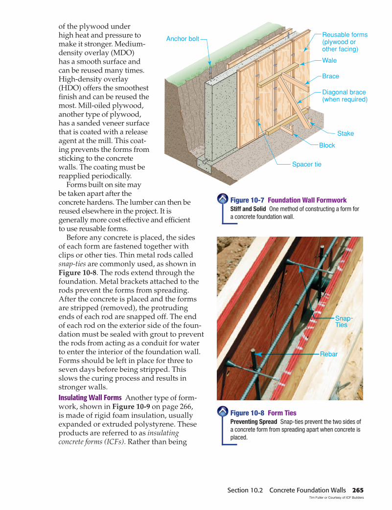
foundation wall. Reusable forms are the most cost effective when a contractor does this work regularly. Forms can also be built on site. In any case, the forms must be accurately constructed and properly braced, as shown in Figure 10-7. This enables them to withstand the forces of the placing and vibrating operations. When concrete is fi rst placed, it puts considerable pressure on the forms. The higher the form, the greater the pressure. If forms are not constructed prop-erly and braced well, the pressure can cause forms to “blow out.” This failure allows concrete to spread over the job site. One or more horizontal members, called wales, are usually required to brace forms.Wall Form Details Wall forms may be made from wood or metal, depending on how durable they must be. Many are made from plywood and lumber. Although any exterior-grade plywood can be used, special form-grade plywood is available. Form-grade plywood made by member mills of APA, the Engineered Wood Associa-tion, is referred to as Plyform. An overlaid surface material is bonded to both sides
264 Chapter 10 Foundation Walls
Brace
Block
Stake
Spacer tie
Anchor bolt
Diagonal brace(when required)
Reusable forms(plywood orother facing)
Wale
of the plywood under high heat and pressure to make it stronger. Medium-density overlay (MDO) has a smooth surface and can be reused many times. High-density overlay (HDO) offers the smoothest fi nish and can be reused the most. Mill-oiled plywood, another type of plywood, has a sanded veneer surface that is coated with a release agent at the mill. This coat-ing prevents the forms from sticking to the concrete walls. The coating must be reapplied periodically.
Forms built on site may be taken apart after the concrete hardens. The lumber can then be reused elsewhere in the project. It is generally more cost effective and effi cient to use reusable forms.
Before any concrete is placed, the sides of each form are fastened together with clips or other ties. Thin metal rods called snap-ties are commonly used, as shown in Figure 10-8. The rods extend through the foundation. Metal brackets attached to the rods prevent the forms from spreading. After the concrete is placed and the forms are stripped (removed), the protruding ends of each rod are snapped off. The end of each rod on the exterior side of the foun-dation must be sealed with grout to prevent the rods from acting as a conduit for water to enter the interior of the foundation wall. Forms should be left in place for three to seven days before being stripped. This slows the curing process and results in stronger walls.Insulating Wall Forms Another type of form-work, shown in Figure 10-9 on page 266, is made of rigid foam insulation, usually expanded or extruded polystyrene. These products are referred to as insulating concrete forms (ICFs). Rather than being
Figure 10-7 Foundation Wall FormworkStiff and Solid One method of constructing a form for a concrete foundation wall.
Figure 10-8 Form TiesPreventing Spread Snap-ties prevent the two sides of a concrete form from spreading apart when concrete is placed.
Section 10.2 Concrete Foundation Walls 265Tim Fuller or Courtesy of ICF Builders
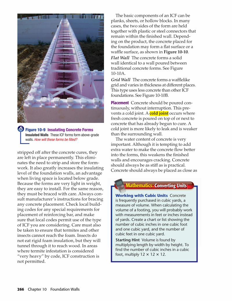
stripped off after the concrete cures, they are left in place permanently. This elimi-nates the need to strip and store the form-work. It also greatly increases the insulating level of the foundation walls, an advantage when living space is located below grade. Because the forms are very light in weight, they are easy to install. For the same reason, they must be braced with care. Always con-sult manufacturer’s instructions for bracing any concrete placement. Check local build-ing codes for any special requirements for placement of reinforcing bar, and make sure that local codes permit use of the type of ICF you are considering. Care must also be taken to ensure that termites and other insects cannot reach the foam. Insects do not eat rigid foam insulation, but they will tunnel through it to reach wood. In areas where termite infestation is considered “very heavy” by code, ICF construction is not permitted.
The basic components of an ICF can be planks, sheets, or hollow blocks. In many cases, the two sides of the form are held together with plastic or steel connectors that remain within the fi nished wall. Depend-ing on the product, the concrete placed for the foundation may form a fl at surface or a waffl e surface, as shown in Figure 10-10.Flat Wall The concrete forms a solid wall identical to a wall poured between traditional concrete forms. See Figure 10-10A.Grid Wall The concrete forms a waffl elike grid and varies in thickness at different places. This type uses less concrete than other ICF foundations. See Figure 10-10B.
Placement Concrete should be poured con-tinuously, without interruption. This pre-vents a cold joint. A cold joint occurs where fresh concrete is poured on top of or next to concrete that has already begun to cure. A cold joint is more likely to leak and is weaker than the surrounding wall.
The water content of concrete is very important. Although it is tempting to add extra water to make the concrete fl ow better into the forms, this weakens the fi nished walls and encourages cracking. Concrete should always be as stiff as is practical. Concrete should always be placed as close as
Working with Cubic Units Concrete is frequently purchased in cubic yards, a measure of volume. When calculating the volume of a footing, you will probably work with measurements in feet or inches instead of yards. Create a chart or list showing the number of cubic inches in one cubic foot and one cubic yard, and the number of cubic feet in one cubic yard.Starting Hint Volume is found by multiplying length by width by height. To fi nd the number of cubic inches in a cubic foot, multiply 12 � 12 � 12.
Converting Units
Figure 10-9 Insulating Concrete FormsInsulated Walls These ICF forms form above-grade walls. How will these forms be fi lled?
266 Chapter 10 Foundation Walls

6" minimum core diameter,horizontal and vertical
Form
Rebar.Reinforceaccording tocodes
Form
possible to where it is needed. This reduces the need to push it around with shovels.
Concrete is normally delivered by ready-mix trucks. As it is placed in the forms, it should be worked to remove air pockets and to help it fl ow. The most basic technique is to jab it repeatedly with a shovel or pipe as it is being poured. This is generally enough for residen-tial foundations. However, a concrete vibrator, sometimes called a stinger, is more effective. It is commonly used in commercial construction.
Crawl-Space WallsCrawl-space foundations are common
in mild climates. A crawl-space foundation is shown in Figure 10-11 on page 268. One of the main advantages of the crawl-space foundation is reduced cost. Little or no excavation or grading is required except for the footings and walls. For crawl-space foundations:• Soil beneath the house must be covered
with a material to block moisture vapor from reaching the fl oor structure. This material, called a vapor retarder, is often 6-mil or 8-mil thick plastic sheeting. The best products are reinforced to minimize tearing.
Figure 10-10 Types of ICF FormsBasic Types A. Standard ICF walls create a channel for concrete that is similar to traditional formwork. B. A waffl e-like grid wall uses less concrete than other ICF foundations.
• The crawl space usually must be ventilated. Check local codes.
• The fl oor framing above the crawl space should be insulated to reduce heat loss.
Poured-concrete or concrete-block piers are often used to support fl oor girders in crawl-space houses. They should be no closer than 12" to the ground. To prevent ground mois-ture from reaching fl oor framing, bare dirt should be covered with 6-mil plastic sheeting. Otherwise, the fl oor framing may absorb enough moisture to encourage fungi. When temperatures favorable for fungus growth are reached, much decay may result. To protect
A B
Flood-Resistant Foundations The building code now requires special construction details for foundations built where fl ooding is likely. Foundations must be designed to resist “fl otation, collapse, or permanent lateral movement” due to stresses caused by fl ood waters.
Go to glencoe.com for this book’s OLC for more information about regional concerns.
Section 10.2 Concrete Foundation Walls 267

the plastic from damage, some builders cover it with a layer of pea (rounded) gravel.
Reinforcement for WallsIn some parts of the country, it is not
required to reinforce concrete foundation walls with steel. Some builders add vertical and horizontal rebar anyway to provide extra strength. The rebar should be centered in the wall. Window and door openings in the wall call for special attention. The concrete over these openings should contain rebar according to local codes. In earthquake hazard zones, the code requires that founda-tion walls be reinforced. Always check local codes for reinforcing requirements.
Where concrete work includes a connect-ing porch or garage wall not poured with the main basement wall, rebar ties must be provided. The rebar is placed as the main wall is poured. Keyways may also be used to resist sideways movement by forming a lock
between the walls. Connecting walls should extend below the normal frost line and be supported by undisturbed soil.
Sill-Plate AnchorsIn wood-frame construction, the sill plate
must be securely fastened to the foundation. In areas exposed to high winds or earth-quakes, well-anchored plates are especially important. For this reason, anchorage requirements are more stringent in such areas. Bolts or other anchoring devices may have to be placed closer together. In some cases they must be connected to reinforcing bar within the wall.
Most builders use ½" diameter L-shaped bolts called anchor bolts (shown in Figure 10-12A). These are embedded in the concrete immediately after the top of the foundation walls have been smoothed. They should be spaced no more than 6' apart and no more than 12" from the ends of any plate section or
Figure 10-11 Crawl-Space FoundationWalls and Piers A crawl-space foundation (shown at left) is sometimes combined with a concrete slab (being prepared at right). Circular piers in the crawl space will support the fl oor framing system.
268 Chapter 10 Foundation WallsDavid R. Frazier Photolibrary, Inc.

Joist
Sill plate
Anchor bolt
Sill sealer
Foundationwall
Washer
Sill plate
Nail strap to sill
wall corner. Each bolt must extend at least 7" into the concrete. A large fl at washer must be used beneath the nut that holds the sill plate in place.
Another type of anchor is a metal strap that is embedded in the concrete, as shown in Figure 10-12B. The legs of the strap wrap around the sill plate.
A sill sealer is often placed under the sill plate on poured walls to smooth any uneven spots that might have occurred during place-ment. If termite shields are used, they should be installed under the plate and sill sealer. A termite shield is typically a continuous length of galvanized sheet metal with the edges bent slightly downward.
Foundation Wall DetailsA foundation wall must often have special
details, such as brick-veneer siding or utility sleeves. These details must be accounted for in the design of the foundation. Masonry Ledges Brick or stone veneer is often used for the outside fi nish over wood-frame walls. In such cases, the foundation must include a masonry ledge, a supporting ledge or an offset about 5" wide, as shown in
Figure 10-13 on page 270. Including a masonry ledge results in a space of about 1" between the masonry and the sheathing that is needed for ease in laying the brick. A base fl ashing is used at the brick layer below the bottom of the sheathing and framing. The fl ashing should be lapped with sheath-ing paper. Weep holes (to provide drainage) are also located at this course and are formed by omitting the mortar in a vertical joint. (Brick-veneer walls are discussed in Chapter 24, “Brick Masonry & Siding.”) Utility Sleeves It is often necessary for pipes, such as the main drain to the sewer or septic system, to pass through the foundation walls. Other pipes may also need to pass through the foundation, including water supply pipes and electrical conduits. It is easier to provide space for these pipes as the forms are being placed rather than drill large holes in the foundation later. Where a pass-through is required, a tight-fi tting foam block is placed within the formwork and secured with nails. A short length of plastic pipe can also be used. These barriers prevent concrete from fl owing into these areas, creat-ing a hole in the wall at that point.
Figure 10-12 Sill-Plate AnchorsSecure Connection A. Anchor bolts embedded in the foundation wall are used to secure the sill plate. B. Some builders use metal straps embedded in the concrete.
A B
Section 10.2 Concrete Foundation Walls 269

Sleeve attachedto wall form
Utility pipe
Sheathing paper
Sheathing
Base flashing extends behind sheathing paper
Sill
5"
Foundation
Weep holes
Metal ties fasten to studs
Masonry veneer
After the forms have been stripped, the block is removed. Later, pipes can be routed through the hole, as shown in Figure 10-14. Any space around them can be sealed with hydraulic cement and waterproofed. Foundation Vents and Windows In crawl-space foundations, metal or wood-framed vents are sometimes installed within the forms before the concrete is poured. Vents are visible in Figure 10-11 on page 268. In full-height foundation walls, frames for small, grade-level windows may also be placed in the forms. The rust-resistant steel frame of these windows will then be locked securely to the foundation. Where larger openings are required, wood frames may have to be inserted in the forms. In this case, the wood is sometimes left in place after the forms are stripped away. This wood must be pres-sure treated. Small anchor bolts should be inserted into pre-drilled holes in the wood frame before the concrete is poured.
Figure 10-13 A Masonry LedgeBrick or Stone Support A foundation wall with a masonry ledge. Note that weep holes in the brick veneer are located just above the base fl ashing.
Figure 10-14 A Pipe SleeveHole Through Foundation A sleeve provides openings through the basement wall for utilities.
270 Chapter 10 Foundation Walls
Asphaltbearingpad
Locationof beam
Sill plate
4" minimumbearing
1/2" clearance,sides, and end
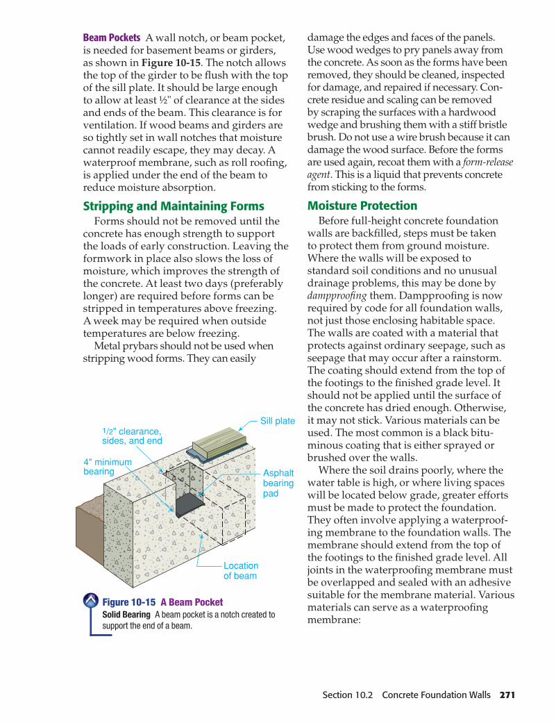
Beam Pockets A wall notch, or beam pocket, is needed for basement beams or girders, as shown in Figure 10-15. The notch allows the top of the girder to be fl ush with the top of the sill plate. It should be large enough to allow at least ½" of clearance at the sides and ends of the beam. This clearance is for ventilation. If wood beams and girders are so tightly set in wall notches that moisture cannot readily escape, they may decay. A waterproof membrane, such as roll roofi ng, is applied under the end of the beam to reduce moisture absorption.
Stripping and Maintaining FormsForms should not be removed until the
concrete has enough strength to support the loads of early construction. Leaving the formwork in place also slows the loss of moisture, which improves the strength of the concrete. At least two days (preferably longer) are required before forms can be stripped in temperatures above freezing. A week may be required when outside temperatures are below freezing.
Metal prybars should not be used when stripping wood forms. They can easily
damage the edges and faces of the panels. Use wood wedges to pry panels away from the concrete. As soon as the forms have been removed, they should be cleaned, inspected for damage, and repaired if necessary. Con-crete residue and scaling can be removed by scraping the surfaces with a hardwood wedge and brushing them with a stiff bristle brush. Do not use a wire brush because it can damage the wood surface. Before the forms are used again, recoat them with a form-release agent. This is a liquid that prevents concrete from sticking to the forms.
Moisture ProtectionBefore full-height concrete foundation
walls are backfi lled, steps must be taken to protect them from ground moisture. Where the walls will be exposed to standard soil conditions and no unusual drainage problems, this may be done by dampproofi ng them. Dampproofi ng is now required by code for all foundation walls, not just those enclosing habitable space. The walls are coated with a material that protects against ordinary seepage, such as seepage that may occur after a rainstorm. The coating should extend from the top of the footings to the fi nished grade level. It should not be applied until the surface of the concrete has dried enough. Otherwise, it may not stick. Various materials can be used. The most common is a black bitu-minous coating that is either sprayed or brushed over the walls.
Where the soil drains poorly, where the water table is high, or where living spaces will be located below grade, greater efforts must be made to protect the foundation. They often involve applying a waterproof-ing membrane to the foundation walls. The membrane should extend from the top of the footings to the fi nished grade level. All joints in the waterproofi ng membrane must be overlapped and sealed with an adhesive suitable for the membrane material. Various materials can serve as a waterproofi ng membrane:
Figure 10-15 A Beam PocketSolid Bearing A beam pocket is a notch created to support the end of a beam.
Section 10.2 Concrete Foundation Walls 271

• 2-ply hot-mopped felts• 55-lb. rolled roofi ng• 6-mil PVC or polyethylene sheeting• 40-mil polymer-modifi ed asphalt• 60-mil fl exible polymer cement• 1⁄8" cement-based fi ber-reinforced
waterproof coating• 60-mil solvent-free liquid-applied
synthetic rubberIn some cases, a multilayer combination
of rigid insulation board, drainage media, and spray- or sheet-membranes may also be approved for use.
Backfi llingBackfi lling, shown in Figure 10-16, is
the process of fi lling in the excavated area around a foundation with soil. This brings the area around the house up to rough grade.
Figure 10-16 Backfi llingCareful Work To avoid damage, only an experienced operator should use heavy equipment to backfi ll a foundation.
FormworkRefer to the fl oor plan on page 273, which
measures 40' � 26'. 1. To determine the total foundation wall
area, assume that the wall is 8' high. Mul-tiply 8' � 132' (perimeter of the building). The answer is 1,056 sq. ft.
2. Assume the wall thickness is 8". Refer to the Table 10-3 on page 273. Read down the col-umn headed “Wall Thickness” to 8". Then read across to the column titled “Forming.” Remember, the wall is to be 8' high. The table shows that the wall will require 7.75 hours per 100 sq. ft. of wall area.
3. Next, calculate the total time for installing the forms. Since you know it will take 7.75 hours for each 100 sq. ft., divide the total number of square feet by 100 and multiply by 7.75.
1,056 � 100 � 10.56 10.56 � 7.75 � 81.84
Concrete Foundation Walls It will take about 82 hours to install the
forms. 4. Next, calculate the time needed to remove
the forms. According to the table, between 2 and 3 hours are needed to remove forms for 100 sq. ft. of an 8' wall. Using the larger number as an example, the calculation would be:
10.56 � 3 � 31.68 It will take about 312∕3 hours total labor
time for removing the forms.
ConcreteYou can also calculate the amount of material
needed using the table. In our example, the wall is 8" thick and has a total area of 1,056 sq. ft. 1. Find the 8" thickness in the column at left.
Reading across, under “Material” you fi nd that 2.47 cu. yds. of concrete are needed for every 100 sq. ft. of wall. Therefore you must again divide the total area by 100 to
272 Chapter 10 Foundation WallsDavid R. Frazier Photolibrary, Inc.

40'- 0"
26'-
0"
BATH. rng
ref.BEDROOM
BEDROOMBEDROOM
KITCHEN
DINING
LIVING ROOM
This estimating and planning exercise will prepare you for national competitive events with organizations such as
SkillsUSA and the Home Builder’s Institute.
fi nd how many hundreds of square feet there are.
1,056 � 100 � 10.56 2. Then multiply by 2.47.
10.56 � 2.47 � 26.08 Round your answer to the next larger
1∕4 cu. yd. Thus, a total of 26.25 cu. yds. of concrete are needed.
LaborTo estimate placement of concrete in the
forms for the wall, again use the table. 1. Under “Concrete Placement,” it says that
1 cu. yd. takes an average of 3.25 hours. 2. Multiply the total cubic yards by the time
required to pour 1 cu. yd. This will tell you the total time required. In our example, 26.25 cu. yds. of concrete are required. Therefore:
26.25 � 3.25 (hours) � 85.31 Rounded off, this comes to 85 1∕3 hours of
labor.
WallsMaterial Forming Concrete Placement
Per 100 Feet of Wall Hours per 100 Square Feet of Wall Hours per Cubic Yard
Wall Thickness (inches)
Cubic Feet Required
Cubic Yards Required
PlaceRemove
Average 3.25 Hours
0' to 4' 4' to 8'
4 33.3 1.24 4.7 7.13 2.0
6 50.0 1.85 4.7 7.75
Varies as to Height8 66.7 2.47 5.0 7.75
10 83.3 3.09 5.0 7.90
12 100.0 3.70 5.0 7.90 3.0
Table 10-3: Estimating Concrete Foundation Walls
Estimating on the JobUsing the table, estimate the time
to install and remove forms, the cubic yards of concrete needed, and the time required to place the concrete for a foundation that measures 43' � 27'. The wall will be 8' high and 10" thick.
Section 10.2 Concrete Foundation Walls 273

After You Read: Self-Check 1. What is a wale? 2. Why might ICFs be used to form foundation walls for a house that was designed to
include a basement recreation room? 3. Why must concrete always be poured in as stiff a mix as is practical? 4. Name three important aspects of crawl-space foundation construction.
Academic Integration: English Language Arts 5. Foundation Walls There are two types of foundation walls: full-height foundation walls
and crawl-space foundation walls. Walls tall enough to create a basement are full-height foundation walls. In mild climates, it is more common to fi nd shorter walls called crawl-space foundation walls. Choose one of these types of foundation walls and write a para-graph outlining its advantages over the other type of foundation wall.
Go to glencoe.com for this book’s OLC to check your answers.
10.2
Falls and Cave-Ins The area around a new foundation wall is an open excavation. Care must be taken when working around this area to prevent falls. To prevent cave-ins, keep trucks and other equipment well away from the perimeter.
Go to glencoe.com for this book’s OLC for more on job safety.
Backfi lling should be done as soon as possible for safety. Backfi lling also makes it easier to transport materials to and from the house. A foundation must not be backfi lled too soon. The weight of the earth can dam-age walls that are not yet strong enough to withstand the pressure. During backfi lling, the vertical portions of drainpipes should be temporarily capped to prevent soil from getting into the drain system.
All foundation drainage, dampproofi ng, and waterproofi ng must be complete before backfi lling begins. Under ideal conditions, the fl oor framing (or fl oor slab) is also in place. This braces the tops of the founda-tion walls. In cases where the wall must be backfi lled before fl oor framing is in place, the walls can be temporarily braced from inside the excavation. This can be done using framing lumber.
Follow the best local building practices when choosing backfi ll material. Do not use materials that expand and drain poorly, such
as clay. Layer gravel into the excavation as needed to ensure proper drainage. Backfi ll 6" to 8" at a time, and compact the soil to prevent it from settling too much later. Do not allow wood debris, such as lumber scraps and tree limbs, to be included in backfi ll. This encourages insects and uneven settlement when limbs and/or wood debris decompose.
274 Chapter 10 Foundation Walls

Figure 10-17 Concrete Block WallsBuilding a Wall Concrete blocks should be stacked near where they will be used. Why might this be?
Block BasicsWhat is a CMU?
Concrete block is popular for building foundation walls (see Figure 10-17). This is because the walls do not require form-work and the blocks are fairly inexpensive. Unlike work on a solid concrete foundation, which must be done all at once, work on a block foundation can start and stop as needed.
Full-height foundation walls are often constructed of eleven courses (rows) of block above the footings, with a 4" solid cap block. The cap block seals the cores of the founda-tion walls. The cores, or cells, are the hollow part of the block. This results in about 7'-4" of headroom between the joists and the base-ment fl oor. A wall with 12 courses of block would add another 8" of headroom.
Strengthening Walls Sometimes a block wall must be strengthened with rebar. If this is required by the building’s designer, #4 to #7 rebar is inserted into the vertical channels created in the wall by successive block cores. Each core containing rebar is then fi lled with concrete. This creates a reinforced column within the wall. These columns should be spaced as required by local codes, depending on the height of the wall and the local soil type. Generally, columns in a 12" thick wall will be spaced no more than 72" OC (on center).
Adding pilasters to the wall is another way to strengthen it. Pilasters are projections resembling columns that may be used to strengthen a wall under a beam or girder. Pilasters are placed on the interior side of the wall and are constructed as high as the bottom of the beam or girder they support. Basement door and window frames should be keyed to the foundation for rigidity and to prevent air leakage.
Types of BlockAny hollow masonry unit is called a
concrete block, or concrete masonry unit (CMU). The most common type is made with Portland cement, a fi ne aggregate, and water. Concrete blocks come in many shapes and sizes for a large variety of appli-cations. Some of the most common sizes are shown in Figure 10-18 on page 276. The most widely used sizes are 8", 10", and 12" wide (nominal dimension). The nominal dimensions allow for the thickness and width of a standard 3⁄8" mortar joint. Thus, the actual dimensions of a standard block are usually 7 5⁄8" high by 15 5⁄8" long. This results in assemblies that measure 8" high and 16" long from centerline to centerline of the mortar joints. A vertical mortar joint is called a head joint. A horizontal joint is called a bed joint.
Concrete Block Walls10.3
Section 10.3 Concrete Block Walls 275David R. Frazier Photolibrary, Inc.

Full cut header Half cut header Solid top 4" or 6" partition
155/8"
75/8"
155/8"
75/8"
75/8"
35/8"or 55/8"
Beam or lintel
Jamb
Stretcher(2 core)
Stretcher(3 core)
Corner Double corneror pier
Bull nose
Specialty blocks are made for specifi c purposes. Split-face blocks have one rough face that looks something like stone, as shown in Figure 10-19. Insulated blocks come in various forms, including some that contain inserts of polystyrene. Heat transfer from one surface to another is reduced when blocks contain rigid insula-tion. Another type of block has one or more glazed surfaces. It can be used as a struc-tural as well as a fi nish material.
Bond PatternsBlock courses are laid in a common bond. A
common bond is the overlapping arrange-ment (see Figure 10-20A). Joints should be tooled smooth to seal them against water seepage. Mortar should be spread fully on all contact surfaces of the block. Such spread-ing is called a full bedding.
When exposed block foundation is used as a fi nished wall for basement rooms, the stack bond pattern can give a pleasing effect. In a stack bond, blocks are placed directly above one another, resulting in continuous vertical joints, as shown in Figure 10-20B. It is
Figure 10-19 Split-Face BlockRough Surface Split-face block is sometimes used for decorative effect in exposed locations.
Figure 10-18 Concrete Masonry UnitsCommon Shapes Typical shapes and sizes of concrete masonry units. Half-length sizes are usually available for most of the units shown above.
276 Chapter 10 Foundation WallsDavid R. Frazier Photolibrary, Inc.

Footingdrain
Footing
Anchor bolt
Concreteblock
Commonbond
4" solid cap block
Parging Stack bond
Reinforced joints
Waterproofcoating
Cove
Windowframe
Key
A B
necessary to add some type of joint reinforce-ment at every second course. This usually consists of steel rods arranged in a grid pattern.Protecting Block Walls Freshly laid block walls should be protected in temperatures below 32°F (0°C). Freezing of the mortar before it has set will often result in low adhesion, low strength, and joint failure. Care must be taken to keep blocks dry on the job. They should be stored on planks or other supports so the edges do not touch the ground. They should be covered for protec-tion against moisture. Concrete block must not get wet just before or during installation.
Block walls should not be backfi lled until they have gained suffi cient strength. Follow the precautions noted in Section 10.2 regard-ing backfi lling.
Silica Dust Cutting concrete block with a circular saw produces silica dust. Inhaling this dust is very hazardous.• When cutting concrete or masonry, use
saws that spray water on the blade.• Use a dust collection system whenever
possible.• Always wear safety goggles and a respira-
tor designed to protect against fi ne, airborne particles.
Go to glencoe.com for this book’s OLC for more on job safety.
Figure 10-20 Bond PatternsFoundation Walls A. Block walls are usually laid in a common bond, as shown here. B. In some cases, walls are laid in a stack bond, with horizontal reinforcing as needed.
Section 10.3 Concrete Block Walls 277

Cutting Block Blocks are usually available in half-length as well as full-length units. It is sometimes necessary to cut a block to fi t it into place. This can be done in two ways. The traditional method is to use a brick hammer and chisel to cut block, as shown in Figure 10-21A. The block is scored on both sides with the chisel to make a clean break. A faster method to cut block is to use a masonry saw, as shown in Figure 10-21B. The saw leaves a smooth, uniform edge but takes time to set up. It is also possible to cut block with a standard circular saw fi tted with a dry-cutting masonry blade, but this method creates clouds of dust and should be avoided whenever possible.
MortarGood mortar is essential for a strong,
solid wall. The strength of the mortar bond depends on:• The type and quantity of mortar.
• The workability, or plasticity, of the mortar.
• The surface texture of the mortar bedding areas.
• The rate at which the masonry units absorb moisture from the mortar.
• The water retention of the mortar.
• The skill of the person laying the block.
Mortar Mixtures Mortar is a mixture of Portland cement, hydrated lime, sand, and water. The individual ingredients are often mixed together on site using a mechanical drum mixer. Mortar mixes for various purposes are shown in Table 10-4. Varying the ingredients yields mortar with different characteristics. A relatively high proportion of Portland cement improves strength. Lime reduces compressive strength but increases fl exibility and makes the mortar “stickier.” Sand reduces shrink-age as the mortar cures.
Mortar can also be made from prepack-aged mortar mix or masonry cement. These products must be mixed with water on site. Mortar mix contains all the dry ingredients, including sand. Masonry cement contains all the dry ingredients except sand. Various masonry cement mixes are shown in Table 10-4. The following types of mortar are the most common:• Type N mortar has average strength for
most general masonry work above grade. It has only moderate compressive strength.
Figure 10-21 Methods for Cutting BlockHand or Power Saw A. To cut by hand, score the blocks along both sides with a chisel. B. A masonry saw is fast and precise.
A B
278 Chapter 10 Foundation WallsDavid R. Frazier Photolibrary, Inc.

Precautions With Mortar Prolonged contact with wet mortar is harmful to your skin. Wear protective clothing, including gloves, to minimize contact with the material. If skin does come into contact with mortar, wash off the mortar as soon as possible. Change clothing that has become saturated with mortar.
Go to glencoe.com for this book’s OLC for more on job safety.
• Type M mortar has high compressive strength and is particularly durable. This makes it good for heavily loaded or below-grade foundation walls.
• Type S mortar has a high tensile strength as well as high compressive strength. This makes it suitable for regions exposed to earthquakes or high winds.
• Type O is a low-compressive-strength mortar used primarily for interior walls.
Mixing and Placing Mortar To ensure that ingredients are well blended, mortar should be mixed in power mixers. For very small jobs, it may be mixed in a wheelbarrow or a mortar tray.
Mortar will stiffen after being mixed because of evaporation and hydration. Evaporation occurs when moisture is lost from the mixture. In that case, water can be added and mixed in to restore the mortar’s workability. Mortar stiffened by hydration should be thrown away. It is not easy to tell whether evaporation or hydration is the cause. A judgment can usually be made on the basis of how much time has passed since initial mixing. Mortar should be used within two-and-a-half hours when the air temperature is 80°F (27°C) or higher, and within three-and-a-half hours when air temperature is below 80°F (27°C). If more time has passed, assume that any stiffness is caused by hydration.
Mortar must be sticky so that it will cling to the concrete block. Mortar is taken from the mortar board with the trowel and then “set” on the trowel with a quick vertical snap of the wrist. The excess will fall from the trowel with the snap of the wrist.
Laying Block Foundation WallsWhat is a mason’s line used for?
Laying block foundation walls is a job for skilled masons. The following section is intended primarily as an overview of the process.
Concrete block is heavy. It should always be stacked close to the work area as to minimize the need to carry it, as shown in Figure 10-17 on page 275. Boards, building paper, or tarpaulins should be used to cover the tops of unfi nished block walls at the end of the day’s work. This prevents water from entering the cores.
Building the CornersThe corners of the wall are built fi rst,
usually four or fi ve courses high. After locating the outside corners of the wall, use a chalked line to mark the footing and help align the fi rst block accurately. A full mortar bed should then be spread with a trowel. The corner block should be laid fi rst and carefully positioned.
Mortar type
Parts by Volume
Portland or blended
cement
Masonry cement type Fine
aggregateM S N
M1–
–1
––
1–
41⁄2 to 621⁄4 to 3
S1⁄2–
––
–1
1–
33⁄8 to 41⁄221⁄4 to 3
NO
––
––
––
11
21⁄4 to 321⁄4 to 3
Table 10-4: Proportions of Mortar Ingredients by Volume
Section 10.3 Concrete Block Walls 279

The fi rst course of the corner should be laid with great care to make sure it is prop-erly aligned, leveled, and plumbed. This will ensure a straight, true wall. After three or four blocks have been laid, use the mason’s level as a straightedge to ensure correct alignment. Make blocks plumb by tapping them with the trowel handle.
After the fi rst course is laid, apply mortar to the top of the face shells. A face shell is the side wall of a concrete block (Figure 10-22). In some cases, a full mortar bed may be specifi ed (Figure 10-23). Mortar for the verti-cal joints can be applied to the ends of the next block or to the ends of the block previ-ously laid. There is the danger of building up the joint size when applying mortar to the ends of both blocks and it is also a wasted motion (multiplied over 300 or 400 blocks set per man per day). Buttering one end of the block is usually suffi cient.
As each course is laid at the corner (Figure 10-24), check it with a level for alignment, for levelness (Figure 10-25), and for plumb (Fig-ure 10-26). Check each block carefully with a level or straightedge to make certain that the
Figure 10-22 Bedding the Face ShellMortar Bed Mortar bedding the face shell in preparation for laying up additional courses.
Figure 10-24 Laying the BlockBlock Pressure The weight of the block will usually be suffi cient pressure to embed it in the mortar.
Figure 10-23 Full Mortar BedNo Bare Spots This is what a full mortar bed should look like.
280 Chapter 10 Foundation WallsDavid R. Frazier Photolibrary, Inc.; Tim Fuller

faces of the blocks are all in the same plane. Check the horizontal spacing by placing the level diagonally across the corners of the blocks (Figure 10-27). A story pole, or course pole, is a board with markings 8" apart. It can be used to gauge the top of the masonry for each course (Figure 10-28).
Figure 10-25 Check for LevelLevel Check the alignment of the blocks frequently.
Figure 10-26 Check for PlumbPlumb After the corners have been built up, be sure to check the corner for plumb before continuing.
Figure 10-27 Check AlignmentAlignment If the blocks have been positioned correctly, the alignment can be checked by holding a level or straightedge diagonally across the corners of the block.
Figure 10-28 A Story PoleHeight A wood story pole marked with the course levels should be used to maintain the proper height of the courses.
Section 10.3 Concrete Block Walls 281David R. Frazier Photolibrary, Inc.; Tim Fuller

Figure 10-30 Fitting the Closure BlockLast Block The closure block is carefully placed in position to complete a course.
Filling In Between CornersWhen fi lling in the wall between the
corners, a mason’s line is stretched from corner to corner for each course, as shown in Figure 10-29. The top, outside edge of each block is laid to this line.
Handling or gripping the block correctly is important and is learned with practice. Roll the block slightly to a vertical position and shove it against the adjacent block. Final positioning of the block must be done while the mortar is soft and plastic. Any attempt to move or shift the block after the mortar has stiffened will break the mortar bond and allow water to seep into the completed installation. “Dead” mortar that has been
picked up from the scaffold or from the fl oor should not be used.
To assure a good bond, mortar should not be spread too far ahead of actual laying of the block or it will stiffen. As each block is laid, excess mortar at the joints is cut off with the trowel. Applying mortar to the vertical joints of the block already in the wall and to the block being set results in well-fi lled joints.
The block that fi lls the fi nal gap in a course between corners, shown in Figure 10-30, is called the closure block. To install this block, spread mortar on all edges of the opening and all four vertical edges of the block itself. The closure block should be carefully low-ered into place.
Figure 10-29 Laying to a LineMason’s Line After the corners have been built up, stretch a mason’s line from corner to corner for each course. Between the corners, set the blocks so their top edges align with the mason’s line.
282 Chapter 10 Foundation WallsDavid R. Frazier Photolibrary, Inc.; Tim Fuller

IntersectionsLoad bearing walls built of intersecting
concrete blocks should not be tied together in a masonry bond, except at the corners. Instead, one wall should end at the face of the other wall, with a control joint at that point. A control joint is a joint that controls movement caused by stress in the wall. The joints are built into the wall in a way that permits slight movement without cracking the masonry. They are continuous from the top of the wall to the bottom. They are the same thickness as the other mortar joints.
Control joints should be placed at the junctions of bearing as well as nonbearing walls, at places where walls join columns and pilasters, and in walls weakened by openings.
For sideways support, bearing walls are tied together with a metal reinforcing bar called tie bar, shown in Figure 10-31. The bends at the ends of tie bars are embedded
in cores fi lled with mortar or concrete. Pieces of metal lath placed under the cores support the concrete or mortar fi lling.
For tying nonbearing block walls to other walls, strips of metal lath or ¼" mesh galva-nized hardware cloth are placed across the joint, as shown in Figure 10-32. The metal strips are placed in alternate courses. When one wall is constructed fi rst, the metal strips are built into the fi rst wall and later tied into the mortar joint of the second wall. Another type of reinforcement is called ladder-reinforcement. Lengths of ladder-shaped metal wire can be set lengthwise into horizontal mortar joints. In some cases, this is required in every third course of a block wall. Ladder-reinforcing signifi cantly strengthens the wall.
Figure 10-31 Tie BarReinforcing a Corner A reinforcing bar can be placed in the mortar joint to tie intersecting walls together.
Figure 10-32 Metal LathReinforcing a Joint Metal lath placed across the joint is used to tie a non-bearing intersecting wall to the main wall.
Section 10.3 Concrete Block Walls 283David R. Frazier Photolibrary, Inc.; Tim Fuller

V-joint
Tooling the JointsWeathertight joints and a neat appear-
ance depend on proper tooling. This is done after the mortar has become “thumb-print hard” (the thumb makes no indenta-tion when pressed into the mortar). Tooling is a process of using shaped metal bars to compact the mortar and force it tightly against the masonry on each side of the
joint. Proper tooling produces joints of uniform appearance, with sharp, clean lines. Unless otherwise specifi ed on the plans, all joints should be tooled in either a concave or V-shape.
Tooling of the head joints should be done fi rst, using a small S-shaped jointer. Tooling of the bed joints should follow, as shown in Figure 10-33. The horizontal joint should
Figure 10-33 Tooling the JointsBed Joints Joints are usually tooled with a jointer shaped to create either A. a V-shaped joint or B. a concave joint
A B
Estimating MaterialsWhen estimating materials for block walls,
you must consider several factors. These include the number of blocks, the amount of mortar, and the cost of labor.
BlockThe number of blocks needed for a founda-
tion can be determined by the area of each wall to be built. 1. Nine 8" � 8" � 16" blocks will make eight
square feet of wall area. Therefore, take the total number of square feet in the wall and divide it by eight. Multiply the result
This estimating and planning exercise will prepare you for national competitive events with organizations, such as
SkillsUSA and the Home Builder’s Institute.Block Walls
by nine. You will then have a good esti-mate of the number of blocks needed for the wall.
For example, consider a house with a 25' � 40' foundation that is 7' high. The simplest way to fi nd the total square footage is to multiply the perimeter times the height. The perimeter (the total length of the four sides) is 130'. Multiply this by 7' to fi nd the total area of the four basement walls, which is 910 sq. ft. Now apply the formula:
910 � 8 � 113.75 113.75 � 9 � 1,023.75 Rounded off, your answer would be 1,024.
Concave joint
284 Chapter 10 Foundation WallsDavid R. Frazier Photolibrary, Inc.; Tim Fuller

2. Next, because the courses overlap or interlock at the corners, subtract one-half block for each corner of each course. The wall in the example would be 11 blocks high; therefore, subtract 5½ blocks for each corner, or 22 blocks altogether.
1,024 � 22 � 1,002 A total of 1,002 blocks would be needed.
This number would be reduced even more to allow for windows or other openings.
3. The number of concrete blocks necessary for a wall can also be determined by refer-ring to the table. In the left column, fi nd the size of the block used. If you select an 8" � 8" � 16" block, the table indicates 110 concrete blocks for each 100 sq. ft. of wall. The walls in our example have an area of 910 sq. ft. Divide this by 100 to fi nd the number of square feet expressed in hun-dreds: 910 � 100 � 9.1.
The table shows that 110 blocks are needed for each 100 sq. ft., so multiply 9.1 by 110 to fi nd the total number of blocks needed: 9.1 � 110 � 1,001 total blocks.
Some adjustment may still be necessary if there are openings in the wall. The table allows for the overlapping of blocks at the corners, so it is not necessary to subtract for this as in the previous example. Note also that the answer is not precisely the same as when calculated by the fi rst method. However, the estimates are very close, and both methods are reliable.
MortarThe number of cubic feet of
mortar needed for a block wall can also be determined from the table.
1. For the walls in our exam-ple, the table shows that 3.25 cu. ft. of mortar would be needed for every 100 sq. ft. of wall area.
2. There are 9.1 hundreds of square feet in the walls. By multiplying 9.1 by 3.25 you fi nd the total amount of mortar needed.
9.1 � 3.25 � 29.575 cu. ft. of mortar, rounded off to 29.6
LaborTo determine labor costs, again consult
the table.1. You will see that 8" � 8" � 16" blocks are
laid at a rate of 18 per hour. 2. Using the fi gure 1,001 for the total num-
ber of blocks, divide by 18 to learn the number of hours needed:
1,001 � 18 � 55.6 3. Multiply the hours needed by the hourly
rate of pay to fi nd the labor cost.
Estimating on the JobUsing the table, determine the number of
blocks, amount of mortar, and labor hours needed to make a 22' � 38' foundation that is 7' high. Concrete blocks that measure 8" � 8" � 16" need to be used.
Lightweight Block
Material for 100 Sq. Ft. of Wall Labor
Size Number of Units Mortar (cu. ft.) Blocks per Hour
8�4�12 146 4.0 24
8�4�16 110 3.25 22
12�4�12 100 3.25 30
8�6�16 110 3.25 21
Concrete Block Material for 100 Sq. Ft. of Wall Labor
Size Number of Units Mortar (cu. ft.) Blocks per Hour
8�8�16 110 3.25 18
8�10�16 110 3.25 16
8�12�16 110 3.25 13
Note: Mortar quantities based on 3∕8" mortar joints, plus 25% waste. For 1∕2" joints add 25%.
Estimating Table for Masonry Blocks
Section 10.3 Concrete Block Walls 285

appear continuous. A jointer for tooling horizontal joints is upturned on one end to prevent gouging the mortar. For concave joints, a tool made from a 5⁄8" round bar is fi ne. For V-shaped joints, a tool made from a 1⁄2" square bar is generally used. After the joints have been tooled, a trowel or stiff brush is used to trim mortar burrs fl ush with the wall face.
Completing the WallsFoundation walls of hollow concrete
block must be capped with a course of solid masonry to distribute the loads from the fl oor beams and to act as a termite barrier. Solid-top blocks, in which the top 4" is of solid concrete, can be used to accomplish this (see Figure 10-18 on page 276). The course can also be covered with a solid 4" thick block called a cap block. A third method is to use stretcher (standard) blocks and then fi ll all cores with concrete or mortar. In this case, a strip of metal lath wide enough to cover
the core spaces is placed in the joints under the top course. The cores are then fi lled and troweled smooth, as shown in Figure 10-34.
Subterranean termites can crawl through hidden cracks in a wall to the wood in the building above. Installing metal termite shields on top of the block walls prevents this.
Installing Anchor BoltsThe house framing rests on preservative-
treated wood sill-plates that are fastened to the top of the foundation walls. This is done by means of anchor bolts 1⁄2" in diameter and 18" long, spaced not more than 8' apart. These anchor bolts are placed at least 16" deep in the cores of the top two courses of block, and the cores are fi lled with concrete or mortar. The threaded end of the bolt should extend above the top of the wall, as shown in Figure 10-35. Pieces of metal lath are placed in the second horizontal joint from the top of the wall and under the cores to be fi lled. The lath supports the concrete or mortar fi lling.
Cleaning Block WallsAny mortar droppings that stick to the
block wall should be allowed to dry slightly before removal with a trowel. The mortar may smear if removed while too soft. When dry and hard, most of the remaining mortar can be removed by rubbing it with a small piece of concrete block and then brushing.
Figure 10-34 Filling CoresTop Course With metal lath in place, the cores of the top-course blocks can be fi lled and troweled smooth.
Figure 10-35 Anchor BoltPosition Carefully Fill cores with concrete or mortar and insert the bolt so that the threads extend above the top of the wall. The bolt should be plumb.
286 Chapter 10 Foundation WallsTim Fuller

Additional TechniquesWhat is radon?
After the walls are complete, additional steps should be taken to ensure that they are able to resist moisture. In some cases, block walls can be assembled using surface-bonding techniques.
Moisture ProtectionLike solid concrete walls, block walls
must either be dampproofed or water-proofed. Block walls are sometimes parged as part of this process. Parging is the pro-cess of spreading mortar or cement plaster over the block, as shown in Figure 10-36. A cove should be formed where the wall joins with the footing, as shown in Figure 10-20 on page 277. The parging should be at least 3⁄8" thick. When the parging is dry, a coating
of asphalt is applied to the exterior of the wall. This, along with a properly designed footing drain, will normally ensure a dry basement.
Sometimes added protection is needed, as when soil is often wet. In such cases, the entire wall should be waterproofed like a solid concrete foundation (see Section 10.2).
Lintels and Bond BeamsIn some situations, concrete is added to a
block wall to span an opening or to provide additional strength. Where openings occur in the foundation, a lintel must be installed over the opening to provide support for the masonry above it. A lintel is a horizontal member that supports the weight of the wall above. A lintel in a masonry wall is like a header in a wood-frame wall. It directs loads around the opening. One way to create a lintel is to use L-shaped steel angles. One leg of the L fi ts under the masonry to support it over the opening.
Another type of lintel is made of rein-forced pre-cast concrete. It is a manufactured product that is delivered to the job site in fi nished form. It is placed over an opening just as a wood header would be placed.
A third way to create a lintel is to use lintel blocks (see Figure 10-18 on page 276). Lintel blocks are temporarily supported over the opening by a wood framework. The open portions of the blocks are then fi lled with concrete and reinforced with rebar. When the concrete has cured, the wood framework can be removed.
Building codes where earthquakes are a hazard may require that masonry walls be strengthened with a bond beam. A bond beam is a course of reinforced concrete or reinforced lintel block. It is sometimes called a collar beam. It is often positioned as the top course of a wall. In some cases it is placed in more than one location. For example, a bond beam might be placed at every fourth course in the wall to stiffen the wall. Bond beams can be created by a continuous course of reinforced lintel
Figure 10-36 PargingMoisture Protection Parging a block wall blocks water infi ltration. It can be applied to above-grade as well as below-grade walls.
Section 10.3 Concrete Block Walls 287

blocks. Another method is to secure metal or plywood forms to the top of the wall. Once the bond beam cures, the forms can be removed and construction can continue.
Surface BondingMortared block walls are the most com-
mon type of concrete block wall. Another technique called surface bonding, or dry-stacking, is also used. It starts out similar to parging. The fi rst course of block is bedded in mortar as usual. Additional courses are stacked dry, with no mortar. Fiberglass-reinforced mortar, or surface-bonding mortar, is then troweled over both sides of the walls in a layer at least 1⁄8" thick, as shown in Figure 10-37. The 1⁄2" long fi bers improve the tensile strength of the mortar much like steel mesh reinforces concrete. Because individual joints are not mortared, walls are built more
quickly and are easier for unskilled workers to install. The coating of surface-bonding mortar provides water resistance.
RadonRadon is a colorless and odorless radio-
active gas that travels through soil. Accord-ing to the U.S. Environmental Protection Agency, radon can be extremely toxic to humans if it builds up inside a house. Long-term exposure to radon has been linked to an increased risk of lung cancer. All types of house foundations, including concrete slabs, should be designed to reduce pen-etration by radon.
Because house foundations are in direct contact with the soil, they are a common entry point for radon. Radon enters through fl oor and wall cracks, expansion joints, gaps around pipes, and even through the pores in concrete. Because radon is soluble in water, it can also enter a basement through water seepage and through water vapor.
In addition, radon is nine times heavier than air, so it tends to accumulate in base-ments. Air circulation and other forces help to distribute radon throughout a house.Radon-Resistant Construction Radon can be found in every area of the country, but it does not affect every region or every house equally. Therefore, steps should be taken during the foundation construction of every house to minimize radon problems. The following protective features are common:Gas-permeable layer This is a 4" thick layer of drainage gravel directly beneath the fl oor slab. It allows radon to move freely beneath the house. A 4" thick layer of sand, topped with geotextile fabric, is an alternative.Soil-gas retarder Polyethylene sheeting 6-mil thick is placed on top of the gas-permeable layer. This prevents radon from moving through the slab.Sealants All openings and joints in the foundation fl oor are sealed to reduce radon entry. Sealant techniques include the use of high-performance caulks as well as plastic covers over sump pits.
Figure 10-37 Surface BondingQuicker and Easier Using surface-bonding mortar to build a block wall eliminates the need to mortar each course as the wall is built.
288 Chapter 10 Foundation Walls

After You Read: Self-Check 1. List three advantages of concrete block foundation walls as compared to solid concrete walls. 2. Name the type of packaged mortar that is most suitable for regions where earthquakes occur. 3. What is a story pole and how is it used when laying concrete block? 4. What is parging and what is its purpose?
Academic Integration: Mathematics 5. Estimating Block Estimate the number of 8" blocks you would need for a foundation
wall that measures 20' in length and 8' in height. Use these facts to guide your estimation: • One block, including a 3⁄8" mortar joint, measures 8" in height. Therefore, 3 blocks will
stack 2' high. • One block, including a 3⁄8" mortar joint, measures 16" in length. Therefore, 3 blocks will
lay out 4' in length.
Many estimating problems can be solved using basic addition, subtraction, multiplication, and division operations. It helps to visualize a problem if you are using mental math.
Step 1 Since 3 blocks lay out 4' in length, you must multiply the length of the wall (20') by 3⁄4 to determine the number of blocks needed for every course. Another way to multiply by 3⁄4 is to multiply by 3, then divide by 4.Step 2 Since 3 blocks stack 2' high, multiply the height of the wall (8') by 3⁄2 to determine the number of courses. Step 3 Multiply the number of blocks in one course by the number of courses to determine the number of 8" blocks that will be needed for the wall. Round up to the nearest whole number.
Go to glencoe.com for this book’s OLC to check your answers.
10.3
Vent pipe A 3" or 4" diameter PVC pipe is connected to the gas-permeable layer. It leads to the roof. The pipe acts as an exhaust to safely vent radon outside the house.Cap course Concrete block foundation walls must incorporate either a continuous course of solid masonry, a continuous course of concrete, or one course of masonry-grouted
solid. This prevents radon from moving through the hollow cores of the block.
Building codes in some parts of the coun-try require the use of radon-resistant founda-tion techniques. Always check local codes for specifi c construction requirements. For more on radon-resistant construction, see Chapter 11, “Concrete Flatwork,” page 299.
Section 10.3 Concrete Block Walls 289

10
Review Content Vocabulary and Academic Vocabulary 1. Use each of these content vocabulary and academic vocabulary words in a sentence or diagram.
Content Vocabulary• footing (p. 256)• wales (p. 264)• cold joint (p. 266)• head joint (p. 275)• bed joint (p. 275)
• story pole (p. 281)• control joint (p. 283)• parging (p. 287)• radon (p. 288)
Academic Vocabulary• framework (p. 258)• incorporate (p. 289)
Like a ProTechnical Terms 2. Work with a classmate to defi ne the follow-
ing terms used in the chapter: monolithic wall (p. 256), haunch boards (p. 258), form brackets (p. 258), stepped footings (p. 259), hydrostatic pressure (p. 262), perimeter drains (p. 262), fi lter fabric (p. 263), fi nes (p. 263), full-height foundation (p. 264), crawl-space foundation (p. 264), stem walls (p. 264), snap-ties (p. 265), insulating concrete forms (ICFs) (p. 265), stinger (p. 267), vapor retarder (p. 267), anchor bolt (p. 268), masonry ledge (p. 269), weep hole (p. 269), dampproofi ng (p. 271), course (p. 275), cell (p. 275), pilaster (p. 275), common bond (p. 276), full bedding (p. 276), stack bond (p. 276), face shell (p. 280), course pole (p. 281), tie bar (p. 283), cap block (p. 286), surface bonding (p. 288).
Review Key Concepts 3. Summarize the function of the footing.
4. Describe the exact location of the footing.
5. Explain the process for forming concrete foundation walls.
6. Describe two types of foundation walls.
7. List the steps in laying a concrete block wall.
8. Describe the types of concrete block used in concrete block walls.
Review and Assessment
10.1
Chapter SummaryFootings provide a base that supports a foundation wall, a pier, or a post. Footings can be reinforced with rebar. Footing drains help prevent damp basements.
Foundation walls may be full-height for basements or shorter for crawl spaces. Poured foundations require forms. Rebar can be added for extra strength. Dampproofi ng and waterproofi ng must be done where moisture is a potential problem.
Concrete block walls do not require formwork. The blocks are fairly inexpensive. Mortar holds the blocks together. Block walls require protection from moisture.
Section
10.2Section
10.3Section
290 Chapter 10 Review and Assessment
Critical Thinking 9. Explain Which type of foundation would
you recommend to an individual planning to build a house in the southern United States who wished to conserve costs as much as possible? Explain the reasons for your recommendation.
Academic and Workplace Applications
10. Estimating Labor Costs On average, it takes between 4.7 and 5.2 man-hours per 100 blocks to lay, clean, and joint 8�8�16 concrete block. How much time would it take 4 workers to build a foundation esti-mated to require 1,200 such blocks?
A man-hour is the amount of work one individual can do per hour.
Step 1: Determine how many man-hours it will take to complete 1,200 blocks given that it will take one man between 4.7 and 5.2 hours to complete 100 blocks.
Step 2: Divide the number of man-hours by the number of workers on the job.
11. Soil Drainage Where the soil drains poorly, where the water table is high, or where living spaces will be located below grade, greater efforts must be made to protect the foundation of a house. Find out more about soil drainage. Write a para-graph explaining why soil in some environ-ments drains poorly.
12. Career Skills Rumblestone Concrete will be undertaking a large concrete project this winter. They will begin work in December, when temperatures are likely to be near or below 32° F. Their new foreman, Jim, has only conducted work in warm climates. You must help Jim ensure that the project is a successful one by outlining some strategies
Short AnswerDirections Write one or two sentences to answer the following questions.
13. How far below grade should footings be placed?
14. What risks are present when freshly laid concrete block walls are exposed to temperatures at or below 32°F?
15. How do you prevent radon from moving through the hollow cores of block in a concrete block foundation wall?
If each item on a test is worth the same number of points, do not spend too much time on questions that are confusing. If you do not know the answer to a question, make a note and move on. Come back to that question later, after you have answered all the other questions.
* These questions will help you practice for nationalcertifi cation assessment.
to protect the freshly placed concrete from freezing temperatures. Write a one-page let-ter to Jim in which you give him advice on how to best protect the concrete.
Chapter 10 Review and Assessment 291