foveated image and video coding - university of...
TRANSCRIPT

Foveated Image and Video Coding
Zhou Wang and Alan C. Bovik
The human visual system (HVS) is highly space-variant in sampling, coding,processing, and understanding of visual information. The visual sensitivity is high-est at the point of fixation and decreases dramatically with distance from the pointof fixation. By taking advantage of this phenomenon, foveated image and videocoding systems achieve increased compression efficiency by removing considerablehigh-frequency information redundancy from the regions away from the fixationpoint without significant loss of the reconstructed image or video quality.
This chapter has three major purposes. The first is to introduce the back-ground of the foveation feature of the HVS that motivates the research effort offoveated image processing. The second is to review various foveation techniquesthat have been used to construct image and video coding systems. The third isto provide in more details a specific example of such systems, which delivers ratescalable codestreams ordered according to foveation-based perceptual importance,and has a wide range of potential applications such as video communications overheterogeneous, time-varying, multi-user and interactive networks.
1.1 Foveated Human Vision and Foveated Image
Processing
Let us start by looking at the anatomy of the human eye. A simplified structureis illustrated in Figure 1.1. The light that passes through the optics of the eye isprojected onto the retina and sampled by the photoreceptors in the retina. Theretina has two major types of photoreceptors known as cones and rods. The rods

2 Chapter 1. Foveated Image and Video Coding
Retina
Lens
Fovea
Pupil
Optic Nerve
Cornea
Figure 1.1: Structure of the human eye.
support achromatic vision in low level illuminations and the cone receptors areresponsible for daylight vision. The cones and rods are non-uniformly distributedover the surface of the retina [1, 2]. The region of highest visual acuity is the fovea,which contains no rods but has the highest concentration of approximately 50,000cones [2]. Figure 1.2 shows the variation of the densities of photoreceptors withretinal eccentricity, which is defined as the visual angle (in degree) between thefovea and the location of the photoreceptor. The density of the cone cells is highestat zero eccentricity (the fovea) and drops rapidly with increasing eccentricity. Thephotoreceptors deliver data to the plexiform layers of the retina, which provideboth direct and inter-connections from the photoreceptors to the ganglion cells.The distribution of ganglion cells is also highly non-uniform as shown in Figure1.2. The density of the ganglion cells drops even faster than the density of thecone receptors. The receptive fields of the ganglion cells also vary with eccentricity[1, 2].
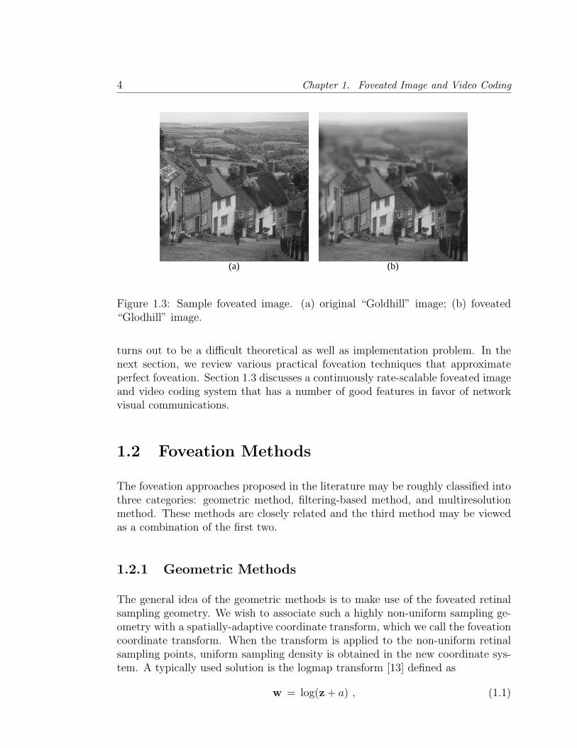
The density distributions of cone receptors and ganglion cells play importantroles in determining the ability of our eyes in resolving what we see. When ahuman observer gazes at a point in a real-world image, a variable resolution imageis transmitted through the front visual channel into the information processingunits in the human brain. The region around the point of fixation (or foveationpoint) is projected onto the fovea, sampled with the highest density, and perceivedby the observer with the highest contrast sensitivity. The sampling density and thecontrast sensitivity decrease dramatically with increasing eccentricity. An exampleis shown in Figure 1.3, where Figure 1.3(a) is the original “Goldhill” image andFigure 1.3(b) is a foveated version of that image. At certain viewing distance, ifattention is focussed at the man at the lower part of the image, then the foveatedand the original images are almost indistinguishable.
Despite the highly space-variant sampling and processing features of the HVS,traditional digital image processing and computer vision systems represent imageson uniformly sampled rectangular lattices, which have the advantages of simpleacquisition, storage, indexing and computation. Nowadays, most digital images

1.1. Foveated Human Vision and Foveated Image Processing 3
Figure 1.2: Photoreceptor and ganglion cell density versus retinal eccentricity.(From [1]).
and video sequences are stored, processed, transmitted and displayed in rectangu-lar matrix format, in which each entry represents one sampling point. In recentyears, there has been growing interest in research work on foveated image process-ing [3, 4, 5, 6, 7, 8, 9, 10, 11, 12, 13, 14, 15, 16, 17, 18, 19, 20, 21, 22, 23, 24, 25,26, 27, 28, 29, 30, 31, 32, 33, 34, 35, 36, 37, 38, 39, 40, 41, 42, 43, 44, 45, 46], whichis targeted at a number of application fields. Significant examples include imagequality assessment [33, 38], image segmentation [24], stereo 3D scene perception[22], volume data visualization [9], object tracking [25], and image watermarking[42]. Nevertheless, the majority of research has been focused on foveated image andvideo coding, communication and related issues. The major motivation is that con-siderable high frequency information redundancy exists in the peripheral regions,thus more efficient image compression can be obtained by removing or reducingsuch information redundancy. As a result, the bandwidth required to transmit theimage and video information over communication channels is significantly reduced.Foveation techniques also supply some additional benefits in visual communica-tions. For example, in noisy communication environments, foveation provides anatural way for unequal error-protection of different spatial regions in the imageand video streams being transmitted. Such an error-resilient coding scheme hasshown to be more robust than protecting all the image regions equally [27, 46]. Foranother example, in an interactive multi-point communication environment whereinformation about the foveated regions at the terminals of the communication net-works is available, higher perceptual quality images can be achieved by applyingfoveated coding techniques [40].
Perfect foveation of discretely-sampled images with smoothly varying resolution
4 Chapter 1. Foveated Image and Video Coding
(a) (b)
Figure 1.3: Sample foveated image. (a) original “Goldhill” image; (b) foveated“Glodhill” image.
turns out to be a difficult theoretical as well as implementation problem. In thenext section, we review various practical foveation techniques that approximateperfect foveation. Section 1.3 discusses a continuously rate-scalable foveated imageand video coding system that has a number of good features in favor of networkvisual communications.
1.2 Foveation Methods
The foveation approaches proposed in the literature may be roughly classified intothree categories: geometric method, filtering-based method, and multiresolutionmethod. These methods are closely related and the third method may be viewedas a combination of the first two.
1.2.1 Geometric Methods
The general idea of the geometric methods is to make use of the foveated retinalsampling geometry. We wish to associate such a highly non-uniform sampling ge-ometry with a spatially-adaptive coordinate transform, which we call the foveationcoordinate transform. When the transform is applied to the non-uniform retinalsampling points, uniform sampling density is obtained in the new coordinate sys-tem. A typically used solution is the logmap transform [13] defined as
w = log(z + a) , (1.1)

1.2. Foveation Methods 5
(a) (b)
Figure 1.4: Application of foveation coordinate transform to images. (a) originalimage; (b) transformed image.
where a is a constant, and z and w are complex numbers representing the positionsin the original coordinate and the transformed coordinate, respectively. Whilethe logmap transform is empirical, it is shown in [34] that precise mathematicalsolutions of the foveation coordinate transforms may be derived directly from givenretinal sampling distributions.
The foveated retinal sampling geometry can be used in different ways. Thefirst method is to apply the foveation coordinate transform directly to a uniformresolution image, thus the underlying image space is mapped onto the new coor-dinate system as exemplified by Figure 1.4. In the transform domain, the imageis treated as a uniform resolution image, and regular uniform-resolution imageprocessing techniques, such as linear and non-linear filtering and compression, areapplied. Finally, the inverse coordinate transform is employed to obtain a “foveat-edly” processed image. The difficulty with this method is that the image pixelsoriginally located at integer grids are moved to non-integer positions, making it dif-ficult to index them. Interpolation and resampling procedures have to be appliedin both the transform and the inverse transform domains. These procedures notonly significantly complicate the system, but may also cause further distortions.
The second approach is the superpixel method [13, 16, 6, 15, 14], in whichlocal image pixel groups are averaged and mapped into superpixels, whose sizesare determined by the retinal sampling density. Figure 1.5 shows a sophisticatedsuperpixel look-up table given in [13], which attempts to adhere with the logmapstructure. However, the number and variation of superpixel shapes make it incon-venient to manipulate. In [16], a more practical superpixel method is used, whereall the superpixels have rectangular shapes. In [14], a multistage superpixel ap-

6 Chapter 1. Foveated Image and Video Coding
Figure 1.5: Logmap superpixel representation. The superpixel mask is applied inthe pixel coordinates. (From [13])
proach is introduced, in which a progressive transmission scheme is implementedby using variable sizes of superpixels in each stage. There are two drawbacks ofthe superpixel methods. First, the discontinuity across superpixels is often veryperceptually annoying. Blending methods are usually used to reduce the boundaryeffect, leading to additional computational cost. Second, when the foveation pointmoves, the superpixel mask has to be recalculated.
In the third method, the foveated retinal geometry is employed to guide thedesign of a non-uniform subsampling scheme on the uniform resolution image. Anexample of foveated sampling design is shown in Figure 1.6 [13]. In [23], uniformgrid images are resampled with variable resolution that matches the human retinasampling density. B-Spline interpolation is then used to reconstruct the foveatedimages. The subsampling idea has also been used to develop foveated sensoringschemes to improve the efficiency of image and video acquisition systems [7, 13].
1.2.2 Filtering Based Methods
The sampling theorem states that the highest frequency of a signal that can berepresented without aliasing is one-half of the sampling rate. As a result, the band-width of perceived local image signal is limited by local retinal sampling density. Inthe category of filtering-based foveation methods, foveation is implemented with ashift-variant low-pass filtering process over the image, where the cut-off frequencyof the filter is determined by the local retinal sampling density.

1.2. Foveation Methods 7
Figure 1.6: Foveated sensor distribution. (From [13])
Since retinal sampling is spatially varying (smoothly), an ideal implementationof foveation filtering would require using a different low-pass filter at each locationin the image. Although such a method delivers very high quality foveated images,it is extremely expensive in terms of computational cost when the local bandwidthis low.
The filter bank method provides a flexible trade-off between the accuracy andthe cost of the foveation filtering process. As illustrated in Figure 1.7 [34], a bank(finite number) of filters with varying frequency responses are first uniformly ap-plied to the input image, resulting in a set of filtered images. The foveated image isthen obtained by merging these filtered images into one image, where the mergingprocess is space-variant according to the foveated retinal sampling density. Thereare a number of issues associated with the design of such filter banks and mergingprocesses. First, the bank of filters can be either low-pass or band-pass, and thusthe merging process should be adjusted accordingly. Second, there are a number offilter design problems. For instance, the filters can be designed either in the spatialor in the frequency domain. For another example, in the design of finite impulseresponse filters, it is important to consider the trade-offs between transition bandsize, ripple size, and implementation complexity (e.g., filter length). Usually, smallripple size is desired to avoid significant ringing effect. Third, since both foveationfiltering and transform-based (e.g., discrete cosine transform (DCT) or wavelet-based) image compression require transforming the image signal into frequencysubbands, they may be combined to reduce implementation and computationalcomplexity. For example, only one-time DCT is used and then both foveation fil-tering and compression can be implemented by manipulating the DCT coefficients.
In [27, 30, 38], the filter bank method was employed as a preprocessing step

8 Chapter 1. Foveated Image and Video Coding
Space-variant Combination
Input Image
Foveated Image
Channel 1
...... Channel 2
Channel N
Filter Bank
Figure 1.7: Filter bank foveation method.
before the standard video compression algorithms such as MPEG and H.26x wereapplied. Significant compression improvement over uniform resolution coding wasobtained because a large amount of visually redundant high frequency informationis removed during the foveation filtering processes. Another important advantageof this system is that it is completely compatible with the video coding standards,because no modification on the encoder/decoder of the existing video coding sys-tems is needed, except for adding a foveation filtering unit in front of the videoencoder. A demonstration of this system is available at [28].
The filter bank method was also used to build an eye tracker-driven foveatedimaging system at the Laboratory for Image and Video Engineering (LIVE) at theUniversity of Texas at Austin [35]. The system detects the fixation point of thesubject in real-time using an eye-tracker. The detected fixation point is then usedto promptly foveate the image or video being displayed on a computer monitoror projected on a large screen mounted on the wall. Since all the processes areimplemented in real time, the subject feels as if he/she were watching the originalimage sequence instead of the foveated one, provided the calibration process hasbeen well-performed.
In [40, 43], foveation filtering was implemented in the DCT domain and com-bined with the quantization processes in standard H.26x and MPEG compression.In [39], such a DCT-domain foveation method is merged into a video transcodingsystem, which takes compressed video streams as the input and re-encoders theminto lower bit rates. Implementing these systems is indeed very challenging be-cause the coding blocks in the current frame need to be predicted from the regionsin the previous frame that may cover multiple DCT blocks and have different andvarying resolution levels. It needs to point out that although the existing standardvideo encoders need to be modified to support foveated coding, these systems arestill standard compatible in the sense that no change is necessary in order for anystandard decoders to correctly decompress the received video streams.
1.2. Foveation Methods 9
1.2.3 Multiresolution Methods
The multiresolution method can be considered as a combination of the geometricand the filtering-based methods, in which the original uniform resolution image istransformed into different scales (where certain geometric operations such as down-sampling are involved), and the image processing algorithms are applied separatelyat each scale (where certain filtering processes are applied).
The multiresolution method has advantages over both geometric and filtering-based methods. First, no sophisticated designs for the geometric transforms orsuperpixels are necessary since scaling can be implemented by simple uniformdownsampling. This saves computation as well as storage space, and makes pixelindexing easy. Second, after downsampling, the number of transformed coefficientsin each scale is greatly reduced. As a result, the computational cost of the filteringprocess decreases.
In [5], a multiresolution pyramid method [47] is applied to an uniform resolu-tion image and a coarse-to-fine spatially adaptive scheme is then applied to selectthe useful information for the construction of the foveated image. In [21], a veryefficient pyramid structure shown in Figure 1.8 is used to foveate images and video.In order to avoid severe discontinuities occurring across stage boundaries in thereconstructed image and video, strong blending postprocessing algorithms wereemployed. This system can be used for real-time foveated video coding and trans-mission. In [36], the system was further improved to create high quality foveatedimages and video that can be used to study the roles of central and peripheralvision in visual tasks such as search, navigation and reading. A demonstration ofthese systems and their software implementation is available at [37].
As a powerful multiresolution analysis tool, the wavelet transform has beenextensively used for various image processing tasks in recent years [48]. A well-designed wavelet transform not only delivers a convenient, spatially localized rep-resentation of both frequency and orientation information of the image signal, butalso allows for perfect reconstruction. These features are important for efficientimage compression. In [19, 26], a non-uniform foveated weighting model in thewavelet transform domain is employed for wavelet foveation. A progressive trans-mission method was also suggested for foveated image communication, where theordering of the transmitted information was determined by the foveated weightingmodel.
In the next section, we will mainly discuss a wavelet-based foveated scalablecoding method proposed in [31, 34], where the foveated weighting model was devel-oped by joint consideration of multiple HVS factors, including the spatial varianceof the contrast sensitivity function, the spatial variance of the local visual cutofffrequency, and the variance of the human visual sensitivity in different wavelet sub-

10 Chapter 1. Foveated Image and Video Coding
Figure 1.8: Foveated multiresolution pyramid. (Adapted from [21])
bands. The ordering of the encoded information not only depends on the foveatedweighting model, but also on the magnitudes of the wavelet coefficients. Thismethod was extended for the design of a prototype for scalable foveated video cod-ing [44, 34]. The prototype was implemented in a specific application environment,where foveated scalable coding was combined with an automated foveation pointselection scheme and an adaptive frame prediction algorithm.
1.3 Scalable Foveated Image and Video Coding
An important recent trend in visual communications is to develop continuouslyrate scalable coding algorithms (e.g., [49, 50, 51, 52, 53, 54, 31, 44]), which al-low the extraction of coded visual information at continuously varying bit ratesfrom a single compressed bitstream. An example is shown in Figure 1.9, wherethe original video sequence is encoded with a rate scalable coder and the encodedbitstream is stored frame by frame. During the transmission of the coded data onthe network, we can scale, or truncate, the bitstream at any place and send themost important bits of the bitstream. Such a scalable bitstream can provide nu-merous versions of the compressed video at various data rates and levels of quality.This feature is especially suited for video transmission over heterogeneous, multi-user, time-varying and interactive networks such as the Internet, where variablebandwidth video streams need to be created to meet different user requirements.The traditional solutions, such as layered video (e.g., [55]), video transcoding (e.g.,[56]), and simply repeated encoding, require more resources in terms of compu-tation, storage space and/or data management. More importantly, they lack theflexibility to adapt to time-varying network conditions and user requirements, be-cause once the compressed video stream is generated, it becomes inconvenient tochange it to an arbitrary data rate. By contrast, with a continuously rate scalablecodec, the data rate of the video being delivered can exactly match the availablebandwidth on the network.

1.3. Scalable Foveated Image and Video Coding 11
less important
bits
more important
bits
Frame
...... ...... ......
bits dropped
bits sent
Figure 1.9: Bitstream scaling in rate scalable video communications. Each barrepresents the bitstream for one frame in the video sequence. The bits in eachframe are ordered according to their importance. (Adapted from [44])
The central idea of foveated scalable image and video coding is to organize theencoded bitstream to provide best decoded visual information at an arbitrary bitrate in terms of foveated perceptual quality measurement. Foveation-based HVSmodels play important roles in these systems. In this section, we first describe awavelet-domain foveated perceptual weighting model, and then explain how thismodel is used for scalable image and video coding.
1.3.1 Foveated Perceptual Weighting Model
Psychological experiments have been conducted to measure the contrast sensitivityas a function of retinal eccentricity (e.g., [21, 57, 58]). In [21], a model that fitsthe experimental data was given by
CT (f, e) = CT0 exp
(αf
e + e2
e2
), (1.2)
where
f : Spatial frequency (cycles/degree);e: Retinal eccentricity (degrees);CT0: Minimal contrast threshold;α: Spatial frequency decay constant;e2: Half-resolution eccentricity constant;CT : Visible contrast threshold.
The best fitting parameters given in [21] are α = 0.106, e2 = 2.3, and CT0 =1/64, respectively. The contrast sensitivity is defined as the reciprocal of the

12 Chapter 1. Foveated Image and Video Coding
Point of Fixation
u
Fovea
Retina
v
e
x = (x , x ) 1 2
Image Plane
Figure 1.10: A typical viewing geometry. Here, v is the distance to the imagemeasured in image width, and θ is eccentricity measured in degrees. (Adaptedfrom [31])
contrast threshold: CS(f, e) = 1/CT (f, e).
For a given eccentricity e, equation (1.2) can be used to find its critical frequencyor so called cutoff frequency fc in the sense that any higher frequency componentbeyond it is imperceivable. fc can be obtained by setting CT to 1.0 (the maximumpossible contrast) and solving for f :
fc(e) =e2 ln
(1
CT0
)
α(e + e2)
(cycles
degree
). (1.3)
To apply these models to digital images, we need to calculate the eccentricityfor any given point x = (x1, x2)
T (pixels) in the image. Figure 1.10 illustratesa typical viewing geometry. For simplicity, we assume the observed image is N -pixel wide and the line from the fovea to the point of fixation in the image isperpendicular to the image plane. Also assume that the position of the foveationpoint xf = (xf
1 , xf2)
T (pixels) and the viewing distance v (measured in image width)from the eye to the image plane are known. The distance from x to xf is givenby d(x) = ‖x − xf‖2 = [(x1 − xf
1)2 + (x2 − xf
2)2]1/2 (measured in pixels). The
eccentricity is then calculated as
e(v,x) = tan−1
(d(x)
Nv
). (1.4)
With (1.4), we can convert the foveated contrast sensitivity and cutoff frequencymodels into the image pixel domain. In Figure 1.11, we show the normalized
1.3. Scalable Foveated Image and Video Coding 13
Pixel Position (pixels)
Spa
tial F
requ
ency
(cy
cles
/deg
ree)
−250 −200 −150 −100 −50 0 50 100 150 200 2500
5
10
15
20
25
30
35
40
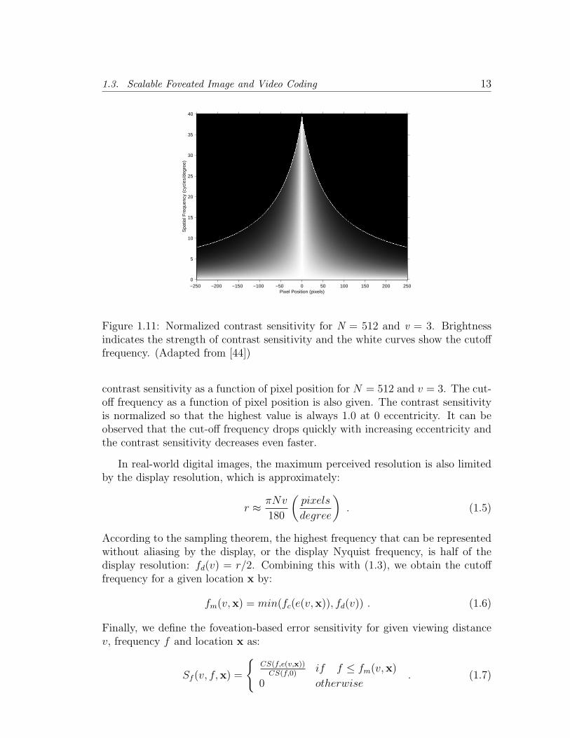
Figure 1.11: Normalized contrast sensitivity for N = 512 and v = 3. Brightnessindicates the strength of contrast sensitivity and the white curves show the cutofffrequency. (Adapted from [44])
contrast sensitivity as a function of pixel position for N = 512 and v = 3. The cut-off frequency as a function of pixel position is also given. The contrast sensitivityis normalized so that the highest value is always 1.0 at 0 eccentricity. It can beobserved that the cut-off frequency drops quickly with increasing eccentricity andthe contrast sensitivity decreases even faster.
In real-world digital images, the maximum perceived resolution is also limitedby the display resolution, which is approximately:
r ≈ πNv
180
(pixels
degree
). (1.5)
According to the sampling theorem, the highest frequency that can be representedwithout aliasing by the display, or the display Nyquist frequency, is half of thedisplay resolution: fd(v) = r/2. Combining this with (1.3), we obtain the cutofffrequency for a given location x by:
fm(v,x) = min(fc(e(v,x)), fd(v)) . (1.6)
Finally, we define the foveation-based error sensitivity for given viewing distancev, frequency f and location x as:
Sf (v, f,x) =
{CS(f,e(v,x))
CS(f,0)if f ≤ fm(v,x)
0 otherwise. (1.7)

14 Chapter 1. Foveated Image and Video Coding
Figure 1.12: Wavelet domain importance weighting mask of a signal foveationpoint. Brightness (logarithmically enhanced for display purpose) indicates theimportance of the wavelet coefficient. (Adapted from [44])
Sf is normalized so that the highest value is always 1.0 at 0 eccentricity.
The wavelet coefficients at different subbands and locations supply informationof variable perceptual importance to the HVS. In [59], psychovisual experimentswere conducted to measure the visual sensitivity in wavelet decompositions. Noisewas added to the wavelet coefficients of a blank image with uniform mid-gray level.After the inverse wavelet transform, the noise threshold in the spatial domain wastested. A model that provided a reasonable fit to the experimental data is [59]:
log Y = log a + k(log f − log gθf0)2 (1.8)
where
Y : Visually detectable noise threshold;θ: Orientation index, representing LL, LH,
HH, and HL subbands, respectively;f : Spatial frequency (cycles/degree);k, f0, gθ: Constant parameters.
f is determined by the display resolution r and the wavelet decomposition levelλ: f = r2−λ. The constant parameters in (1.8) are tuned to fit the experimentaldata. For gray scale models, a is 0.495, k is 0.466, f0 is 0.401, and gθ is 1.501, 1,and 0.534 for the LL, LH/HL, and HH subbands, respectively. The error detectionthresholds for the wavelet coefficients can be calculated by:
Tλ,θ =Yλ,θ
Aλ,θ
=a10k(log(2λf0gθ/r))2
Aλ,θ
, (1.9)

1.3. Scalable Foveated Image and Video Coding 15
where Aλ,θ is the basis function amplitude given in [59]. We define the errorsensitivity in subband (λ, θ) as Sw(λ, θ) = 1/Tλ,θ.
For a given wavelet coefficient at position x ∈ Bλ,θ, where Bλ,θ denotes the setof wavelet coefficient positions residing in subband (λ, θ), its equivalent distancefrom the foveation point in the spatial domain is given by
dλ,θ(x) = 2λ∥∥∥x− xf
λ,θ
∥∥∥2
for x ∈ Bλ,θ , (1.10)
where xfλ,θ is the corresponding foveation point in subband (λ, θ). With the equiv-
alent distance, and also considering (1.7), we have
Sf (v, f,x) = Sf (v, r2−λ, dλ,θ(x)) for x ∈ Bλ,θ . (1.11)
Considering both Sw(λ, θ) and Sf (v, f,x), a wavelet domain foveation-based visualsensitivity model is achieved:
S(v,x) = [Sw(λ, θ)]β1 · [Sf (v, r2−λ, dλ,θ(x))]β2
x ∈ Bλ,θ , (1.12)
where β1 and β2 are parameters used to control the magnitudes of Sw and Sf ,respectively.
For a given wavelet coefficient at location x, the final weighting model is ob-tained by integrating S(v,x) over v:
Ww(x) =
∫ ∞
0+
p(v)S(v,x) dv , (1.13)
where p(v) is the probability density distribution of the viewing distance v [31].Figure 1.12 shows the importance weighting mask in the DWT domain. Thismodel can be easily generated for the case of multiple foveation points:
Ww(x) = W jw(x), j ∈ arg min
i∈{1,··· ,K}
{∥∥∥x− xfi,λ,θ
∥∥∥2
}, (1.14)
where K is the number of foveation points, xfi,λ,θ is the position of the i-th foveation
point in the subband (λ, θ), and W iw(x) is the wavelet-domain foveated weighting
model obtained with the i-th foveation point.
1.3.2 Embedded Foveation Image Coding
The embedded foveation image coding (EFIC) system [31] is shown in Figure 1.13.Firstly, the wavelet transform is applied to the original image. The foveated per-

16 Chapter 1. Foveated Image and Video Coding
ceptual weighting mask calculated from given foveation points or regions is thenused to weight the wavelet coefficients. Next, we encode the weighted wavelet co-efficients using a modified set partitioning in hierarchical trees (SPIHT) encoder,which is adapted from the SPIHT coder proposed in [51]. Finally, the output bit-stream of the modified SPIHT encoder, together with the foveation parameters,is transmitted to the communication network. At the receiver side, the weightedwavelet coefficients are obtained by applying the modified SPIHT decoding algo-rithm. The foveated weighting mask is then calculated in exactly the same way asat the encoder side. Finally, the inverse weighting and inverse wavelet transformare applied to obtain the reconstructed image. Between the sender, the commu-nication network and the receiver, it is possible to exchange information aboutnetwork conditions and user requirements. Such feedback information can be usedto control the encoding bit-rate and foveation points. The decoder can also trun-cate (scale) the received bitstream to obtain any bit rate image below the encoderbit rate.
The modified SPIHT algorithm employed by the EFIC system uses an embed-ded bit-plane coding scheme. The major purpose is to progressively select andencoder the most important remaining bit in the wavelet representation of the im-age. An important statistical feature of natural images that has been successfullyused by the embedded zero tree wavelet (EZW) [49] and SPIHT [51] algorithmsis that the wavelet coefficients which are less significant have structural similarityacross the wavelet subbands in the same spatial orientation. The zerotree structurein EZW and the spatial orientation tree structure in SPIHT capture this structuralsimilarity very effectively. During encoding, the wavelet coefficients are scannedmultiple times. Each time consists of a sorting pass and a refinement pass. Thesorting pass selects the significant coefficients and encodes the spatial orientationtree structure. A coefficient is significant if its magnitude is larger than a thresh-old value, which decreases by a factor of 2 for each successive sorting pass. Therefinement pass outputs one bit for each selected coefficient. An entropy codercan be employed to further compress the output bitstream. In EFIC, the waveletcoefficients being encoded are weighted, which leads to increased dynamic rangeof the coefficients. This not only increases the number of scans, but also increasesthe number of bits to encode the large coefficients. The modified SPIHT algo-rithm employed by EFIC limits the maximum number of bits for each coefficientand scans only the strongly weighted coefficients in the first several scans. Bothof these modifications reduce computational complexity and increase the overallcoding efficiency.
Figure 1.14 shows the 8 bits/pixel gray scale “Zelda” image encoded withSPIHT and EFIC, where the foveated region is at the center of the image. Ata low bit-rate of 0.015625 bits/pixel with compression ratio (CR) equaling 512:1,the mouth, nose, and eye regions are hardly recognizable in the SPIHT coded

1.3. Scalable Foveated Image and Video Coding 17
Wavelet Transform
Output Modified SPIHT
Encoding Weighting
Original Image
Wavelet Coefficients
Weighted Wavelet Coefficients
Weight Calculation
Foveation Points
Bit Stream
Rate Control
Coded Bitstream
Figure 1.13: EFIC encoding system. (Adapted from [31])
image, whereas those regions in the EFIC coded image exhibit some useful in-formation. At a medium bit-rate of 0.0625 bits/pixe (CR = 128:1), SPIHT stilldecodes a quite blurry image, while EFIC gives much more detailed informationover the face region. Increasing the bit-rate to as high as 0.25 bits/pixel (CR =25), the EFIC coded image approaches uniform resolution. The decoded SPIHTand EFIC images both have high quality and are almost indistinguishable. Moredemonstration images for EFIC can be found at [32].
The EFIC decoding procedure can also be viewed as a progressive foveationfiltering process with gradually decreasing foveation depth. The reason may beexplained as follows: Note that the spectra of natural image signals statisticallyfollow the power law 1/fp (see [60] for a review). As a result, the low-frequencywavelet coefficients are usually larger than the high-frequency ones, thus generallyhave better chances to be reached earlier in the embedded bit-plane coding process.Also notice that the foveated weighting process shifts down the bit-plane levels ofall the coefficients in the peripheral regions. Therefore, at the same frequency level,the coefficients at the peripheral regions generally occupy lower bit-planes than thecoefficients at the region of fixation. If the available bit-rate is limited, then theembedded bit-plane decoding process corresponds to applying a higher-bandwidthlow-pass filter to the region of fixation and a lower-bandwidth low-pass filter tothe peripheral regions, thereby foveates the image. With the increase of bit-rate,more bits for the high-frequency coefficients in the peripheral regions are received,thus the decoded image becomes less foveated. This is well demonstrated by theEFIC coded images shown in Figure 1.14.
1.3.3 Foveation Scalable Video Coding
The foveated scalable video coding (FSVC) system [44] follows the general methodof motion estimation/motion compensation-based video coding. It first divides the

18 Chapter 1. Foveated Image and Video Coding
(a) (b)
(c) (d)
(e) (f)
Figure 1.14: “Zelda” image compressed with SPIHT and EFIC algorithms. (a)SPIHT compressed image, compression ratio (CR) = 512:1; (b) EFIC compressedimage, CR = 512:1; (c) SPIHT compressed image, CR = 128:1; (b) EFIC com-pressed image, CR = 128:1; (e) SPIHT compressed image, CR = 32:1; (f) EFICcompressed image, CR = 32:1. (Adapted from [31])

1.3. Scalable Foveated Image and Video Coding 19
DWT Weighting Encoding
Frame Prediction
Prediction Error Calculation
Rate Control
Foveation-based HVS Modeling
Inverse DWT
Inverse Weighting
Decoding
Buffering
I
I, P
Orignal Sequence
Encoded Bitstream
Figure 1.15: FSVC encoding system. (Adapted from [44])
input video sequence into groups of pictures (GOPs). Each GOP has one intra-coding frame (I frame) at the beginning and the rest are predictive coding frames(P frames). The diagram of the encoding system is shown in Figure 1.15. The Iframes are encoded using the same way as in the EFIC algorithm described above.The encoding of P frames is more complicated and is different from other videocoding algorithms in that it uses two instead of one version of the previous frames.One is the original previous frame and the other is a feedback decoded versionof the previous frame. The final prediction frame is the weighted combination ofthe two motion compensated prediction frames. The combination is based on thefoveated weighting model.
The prototype FSVC system allows to select multiple foveation points, mainlyto facilitate the requirements of large foveation regions and multiple foveated re-gions of interest. It also reduces the search space of the foveation points by dividingthe image space into blocks and limiting the candidate foveation points to the cen-ters of blocks. This strategy not only decreases implementation and computationalcomplexity, but also reduces the number of bits needed to encode the positions ofthe foveation points. In practice, the best way of foveation point(s) selection isapplication dependant. The FSVC prototype is very flexible such that differentfoveation point selection schemes can be applied to a single framework.
We implemented the FSVC prototype in a specific application environmentfor video sequences with human faces. A face-foveated video coding algorithm isuseful to effectively enhance the visual quality in specific video communicationenvironments such as videoconferencing.
The methods to choose foveation points for I frames and P frames are different.In the I frames, a face detection algorithm similar to that in [61] is used, which

20 Chapter 1. Foveated Image and Video Coding
detects possible face regions by the skin color information [62] and uses a binarytemplate matching method to detect human faces in the skin-color regions. Adifferent strategy is used for P frames, where we concentrate on the regions in thecurrent P frame that provide us with new information from its previous frame, inwhich the prediction errors are usually larger than other regions. The potentialproblem of this method is that the face regions may lose fixation. To solve thisproblem, an unequal error thresholding method is used to determine foveationregions in P frames, where a much smaller prediction error threshold value is usedto capture the changes occurring in the face regions. In Figure 1.16, we showfive consecutive frames in the “Silence” sequence and the corresponding selectedfoveation points, in which the first frame is an I frame and the rest are P frames.
In fixed-rate motion compensation-based video coding algorithms, a commonchoice is to use the feedback decoded previous frame as the reference frame for theprediction of the current frame. This choice is infeasible for continuously scalablecoding because the decoding bit rate may be different from the encoding bit rateand is unavailable to the encoder. In [52], a low base rate is defined and the decodedand motion compensated frame at the base rate is used as the prediction. Thissolution avoids the significant error propagation problems, but when the decodingbit rate is much higher than the base rate, large prediction errors may occur and theoverall coding efficiency may be seriously affected. A new solution to this problemis used in the FSVC system, where the original motion compensated frame andthe base rate decoded and motion compensated frame are adaptively combinedusing the foveated weighting model. The idea is to assign more weight to the baserate motion compensated frame for difficult prediction regions, and more weightto the original motion compensated frame for easy prediction regions. By usingthis method, error propagation becomes a small problem, while at the same time,better frame prediction is achieved, which leads to smaller prediction errors andbetter compression performance.
Figure 1.16 shows the FSVC compression results of the “Silence” sequence. Itcan be observed that the spatial quality variance in the decoded image sequencesis well adapted to the time-varying foveation point selection scheme. Figure 1.17demonstrates the scalable feature of the FSVC system, which shows the recon-structed 32nd frame of the “Salesman” video sequence decoded at 200, 400 and800 Kbits/sec, respectively. The reconstructed video sequences are created fromthe same FSVC-encoded bitstream by truncating the bitstream at different places.Similar to Figure 1.14, the decoded images exhibit decreased foveation depth withincreasing bit rate.

1.3. Scalable Foveated Image and Video Coding 21
Figure 1.16: Consecutive frames of the “Silence” sequence (left); the FSVC com-pression results at 200 Kbits/sec (middle); and the selected foveation points (right).(Adapted from [44])

22 Chapter 1. Foveated Image and Video Coding
(a) (b)
(c) (d)
Figure 1.17: Frame 32 of the “Salesman” sequence (a) compressed using FSVC at200 Kbits/sec (b), 400 Kbits/sec (c), and 800 Kbits/sec (d), respectively. (Adaptedfrom [44])

1.4. Discussions 23
1.4 Discussions
This chapter first introduces the background and motivations of foveated imageprocessing, and then reviews the various foveation techniques that are used forthe development of image and video coding systems. To give examples on spe-cific implementations of such systems, we described in more details the EFIC andthe FSVC systems, which supply continuously rate-scalable codestrems orderedaccording to foveation-based perceptual importance. Such systems have a numberof potential applications.
One direct application is network image browsing. There are two significantexamples. In the first example, prior to using the encoding algorithm, the foveationpoint(s) are predetermined. The coding system then encodes the image with highbit-rate and high quality. One copy of the encoded bitstream is stored at the serverside. When the image is required by a client, the server sends the bitstream tothe client progressively. The client can stop the transmission at any time once thereconstructed image quality is satisfactory. In the second example, the foveationpoint(s) are unknown to the server before transmission. Instead of a fully encodedbitstream, a uniform resolution coarse quality version of the image is precomputedand stored at the server side. The client first sees the coarse version of the imageand clicks on the point of interest in that image. The selected point of interest issent back to the server and activates the scalable foveated encoding algorithm. Theencoded bitstream that has a foveation emphasis on the selected point of interestis then transmitted progressively to the client.
Another application is network videoconferencing. Compared with traditionalvideoconferencing systems, a foveated system can deliver lower data rate videostreams since much of the high frequency information redundancy can be removedin the foveated encoding process. Interactive information such as the locationsof the mouse, touch screen and eye-tracker can be sent as feedback informationto the other side of the network and used to define the foveation points. Facedetection and tracking algorithm may also help to find and adjust the foveationpoints. Furthermore, in a highly heterogeneous network, the available bandwidthcan change dramatically between two end users. A fixed bit-rate video streamwould either be terminated suddenly (when the available bandwidth drops belowthe fixed encoding bit-rate) or suffer from the inefficient use of the bandwidth(when the fixed bit-rate is lower than the available bandwidth). By contrast, arate scalable foveated videoconferencing system can deal with these problems moresmoothly and efficiently.
The most commonly used methods for robust visual communications on noisychannels are error resilience coding at the source or channel coders and error con-cealment processing at the decoders [63]. Scalable foveated image and video stream

24 Chapter 1. Foveated Image and Video Coding
provides us with the opportunity to do a better job by taking advantage of its opti-mized ordering of visual information in terms of perceptual importance. It has beenshown that significant improvement can be achieved by unequal error protectionfor scalable foveated image coding and communications [41].
Active networks are a hot research topic in recent years [64]. It allows thecustomers to send not only static data but also programs that are executable at therouters or switches within the network. An active network becomes more useful andeffective for visual communications if an intelligent scheme is employed to modifythe visual contents being delivered in a smart and efficient way. The propertiesof scalable foveated image/video streams provide a good match to the features ofactive networks because the bit rate of the video stream can be adjusted accordingto the network conditions monitored at certain routers/switches inside the network(instead of at the sender side), and the feedback foveation information (points anddepth) at the receiver side may also be dealt with at the routers/switches. Thismay result in quicker responses that benefit real-time communications.
Finally, a common critical issue in all foveated image processing applications ishow the foveation points or regions should be determined. Depending on the ap-plication, this may be done either interactively or automatically. In the interactivemethod, an eye tracker is usually used to track the eye movement and send theinformation back to the foveated imaging system in real time. In most applicationenvironments, however, the eye tracker is not available or is inconvenient. A morepractical way is to ask the users to indicate fixation points using a mouse or touchscreen. Another possibility is to ask the users to indicate the object of interest,and an automatic algorithm is then used to track the user-selected object as thefoveated region in the image sequence that follows. Automatical determinationof foveation points is itself a difficult but interesting research topic, and is closelyrelated to psychological visual search research (see [65] for a review). In the imageprocessing literature, there also has been previous research towards understandinghigh level and low level processes in deciding human fixation points automatically(e.g., [22, 66, 44, 67]). High level processes are usually context dependent andinvolve a cognitive understanding of the image and video being observed. Forexample, once a human face is recognized in an image, the face area is likely tobecome a heavily fixated region. In a multimedia environment, audio signals mayalso be linked to image objects in the scene and help to determine foveation points[34]. Low level processes determine the points of interest using simple local fea-tures of the image [66, 67]. In [22], three-dimensional depth information is alsoemployed to help find foveation points in an active stereo vision system. Althoughit is argued that it is always difficult to decide foveation points automatically, webelieve that it is feasible to establish a statistical model that predicts them in ameasurably effective way.

Bibliography
[1] W. S. Geisler and M. S. Banks, “Visual performance,” in Handbook of Optics, M.Bass, ed., McGraw-Hill, 1995.
[2] B. A. Wandell, Foundations of Vision, Sinauer Associates, Inc.,1995.
[3] E. L. Schwartz, “Spatial mapping in primate sensory projection: Analytic structureand relevance to perception,” Biological Cybernetics, vol. 25, pp. 181-194, 1977.
[4] E. L. Schwartz, “Computational anatomy and functional architecture of striatecortex: a spatial mapping approach to perceptual coding,” Vision Research, vol.20, pp. 645-669, 1980.
[5] P. J. Burt, “Smart sensing within a pyramid vision machine,” Proc. IEEE, vol. 76,pp. 1006-1015, Aug. 1988.
[6] C. Bandera and P. Scott, “Foveal machine vision systems,” IEEE Inter. Conf.System, Man and Cybernetics, pp. 596-599, Nov. 1989.
[7] A. S. Rojer and E. L. Schwartz, “Design considerations for a space-variant visualsensor with complex-logarithmic geometry,” IEEE Inter. Conf. Pattern Recognition,vol. 2, pp. 278-285, 1990.
[8] C. Weiman, “Video compression via a log polar mapping,” Real Time Image Pro-cessing II, Proc. SPIE, vol. 1295, pp. 266–277, 1990.
[9] M. Levoy and R. Whitaker, “Gaze-Directed Volume Rendering,” Computer Graph-ics, vol. 24, no. 2, pp. 217-223, 1990.
[10] Y. Y. Zeevi and E. Shlomot, “Nonuniform sampling and antialiasing in image rep-resentation,” IEEE Trans. Signal Processing, vol. 41, no. 3, pp. 1223-1236, Mar.1993.
[11] P. L. Silsbee, A. C. Bovik and D. Chen, “Visual pattern image sequence coding,”IEEE Trans. Circuits and Systems for Video Tech., vol. 3, no. 4, pp. 291-301, Aug.1993.
[12] A. Basu, A. Sullivan and K. J. Wiebe, “Variable resolution teleconferencing,” IEEEInter. Conf. Systems, Man, and Cybernetics, pp. 170-175, Oct. 1993.
26 Bibliography
[13] R. S. Wallace, P. W. Ong, B. Bederson and E. L. Schwartz, “Space variant imageprocessing,” International Journal of Computer Vision, vol.13, no. 1, pp. 71-90,1994.
[14] N. Tsumura, C. Endo, H. Haneishi and Y. Miyake, “Image compression and de-compression based on gazing area,” Human Vision and Electronic Imaging, Proc.SPIE, vol. 2657, pp. 361–367, 1996.
[15] P. Camacho, F. Arrebola and F. Sandoval, “Shifted fovea multiresolution geome-tries,” IEEE Inter. Conf. Image Processing, vol. 1, pp. 307-310, 1996.
[16] P. Kortum and W. S. Geisler, “Implementation of a foveal image coding system forimage bandwidth reduction,” Human Vision and Electronic Imaging, Proc. SPIE,vol. 2657, pp. 350-360, 1996.
[17] T. L. Arnow and W. S. Geisler, “Visual detection following retinal damage: Pre-diction of an inhomogeneous retino-cortical model,” Human Vision and ElectronicImaging, Proc. SPIE, vol. 2674, pp. 119-130, 1996.
[18] T. H. Reeves and J. A. Robinson, “Adaptive foveation of MPEG video,” ACMMultimedia, pp. 231-241, 1996.
[19] E.-C. Chang and C. Yap, “A wavelet approach to foveating images,” ACM Sympo-sium on Computational Geometry, pp. 397-399, June 1997.
[20] A. Basu and K. J. Wiebe, “Videoconferencing using spatially varying sensing withmultiple and moving fovea,” IEEE Trans. Systems, Man and Cybernetics, vol. 28,no. 2, pp. 137-148, Mar. 1998.
[21] W. S. Geisler and J. S. Perry, “A real-time foveated multiresolution system for low-bandwidth video communication,” Human Vision and Electronic Imaging, Proc.SPIE, vol. 3299, pp. 294-305, July 1998.
[22] W. N. Klarquist and A. C. Bovik, “FOVEA: A foveated vergent active stereo visionsystem for dynamic three-dimensional scene recovery,” IEEE Trans. Robotics andAutomation, vol. 14, no. 5, pp. 755-770, Oct. 1998.
[23] T. Kuyel, W. Geisler and J. Ghosh, “Retinally reconstructed images: digital imageshaving a resolution match with the human eyes,” IEEE Trans. System, Man andCybernetics, Part A: Systems and Humans, vol. 29, no. 2, pp. 235-243, Mar. 1999.
[24] J. M. Kinser, “Foveation from pulse images,” IEEE Inter. Conf. Information Intel-ligence and Systems, pp. 86-89, 1999.
[25] R. Etienne-Cummings, J. van der Spiegel, P. Mueller and M.-Z. Zhang, “A foveatedsilicon retina for two-dimensional tracking,” IEEE Trans. Circuits and Systems II,vol. 47, no. 6, pp. 504-517, June 2000.
[26] E.-C. Chang, S. Mallat and C. Yap, “Wavelet foveation,” Journal of Applied andComputational Harmonic Analysis, vol. 9, no. 3, pp. 312-335, Oct. 2000.

Bibliography 27
[27] S. Lee, Foveated video compression and visual communications over wireless andwireline networks, Ph.D. dissertation, Dept. of ECE, University of Texas at Austin,May 2000.
[28] S. Lee and A. C. Bovik, “Foveated video demonstration,” Dept. of ECE, Universityof Texas at Austin, http://live.ece.utexas.edu/research/foveated video/demo.html,2000.
[29] S. Daly, K. Matthews and J. Ribas-Corbera, “As plain as the noise on your face:Adaptive video compression using face detection and visual eccentricity models,”Journal of Electronic Imaging, vol. 10, pp. 30-46, Jan. 2001.
[30] S. Lee, M. S. Pattichis and A. C. Bovik, “Foveated video compression with optimalrate control,” IEEE Trans. Image Processing, vol. 10, no. 7, pp. 977-992, July 2001.
[31] Z. Wang and A. C. Bovik, “Embedded foveation image coding,” IEEE Trans. ImageProcessing, vol. 10, no. 10, pp. 1397-1410, Oct. 2001.
[32] Z. Wang and A. C. Bovik, “Demo images for ‘embedded foveation image coding’,”http://www.cns.nyu.edu/˜zwang/files/research/efic/demo.html, 2001.
[33] Z. Wang, A. C. Bovik, and L. Lu, “Wavelet-based foveated image quality measure-ment for region of interest image coding,” IEEE Inter. Conf. Image Processing, vol.2, pp. 89-92, Oct. 2001.
[34] Z. Wang, Rate scalable foveated image and video communications, Ph.D. disserta-tion, Dept. of ECE, University of Texas at Austin, Dec. 2001.
[35] U. Rajashekar, Z. Wang and A. C. Bovik, “Real-time foveation: An eye tracker-driven imaging system,” http://live.ece.utexas.edu/research/realtime foveation/,2001.
[36] J. S. Perry and W. S. Geisler, “Gaze-contingent real-time simulation of arbitraryvisual fields,” Human Vision and Electronic Imaging, B. Rogowitz and T. Pappas,eds., Proc. SPIE, vol. 4662, San Jose, CA, 2002.
[37] “Space variant imaging,” Center for Perceptual Systems, University of Texas atAustin, http://www.svi.cps.utexas.edu/, 2002.
[38] S. Lee, M. S. Pattichis and A. C. Bovik, “Foveated video quality assessment,” IEEETrans. Multimedia, vol. 4, no. 1, pp. 129-132, Mar. 2002.
[39] S. Liu, DCT domain video foveation and transcoding for heterogeneous video com-munication, Ph.D. dissertation, Dept. of ECE, University of Texas at Austin, May2002.
[40] H. R. Sheikh, S. Liu, Z. Wang and A. C. Bovik, “Foveated multipoint videoconfer-encing at low bit rates,” IEEE Inter. Conf. Acoust., Speech, and Signal Processing,vol. 2, pp. 2069-2072, May 2002.

28 Bibliography
[41] M. F. Sabir, Unequal error protection for scalable foveated image communication,Master’s thesis, Dept. of ECE, University of Texas at Austin, May 2002.
[42] A. Koz and A. Alatan, “Foveated image watermarking,” IEEE Inter. Conf. ImageProcessing, vol. 3, pp. 661-664, Sept. 2002.
[43] H. R. Sheikh, B. L. Evans and A. C. Bovik, “Real-time foveation techniques for lowbit rate video coding,” Real-time Imaging, vol. 9, no. 1, pp. 27-40, Feb. 2003.
[44] Z. Wang, L. Lu and A. C. Bovik, “Foveation scalable vidoe coding with automaticfixation selection,” IEEE Trans. Image Processing, vol. 11, no. 2, pp. 243-254, Feb.2003.
[45] S. Lee and A. C. Bovik, “Fast algorithms for foveated video processing,” IEEETrans. Circuits and Systems for Video Tech., vol. 13, no. 2, pp. 149 -162, Feb. 2003.
[46] S. Lee, C. Podilchuk, V. Krishnan and A. C. Bovik, “Foveation-based error resilienceand unequal error protection over mobile networks,” Journal of VLSI Signal Pro-cessing, vol. 34, no. 1/2, pp. 149-166, May 2003.
[47] P. J. Burt and E. H. Adelson, “The Laplacian pyramid as a compact image code,”IEEE Trans. Communications, vol. 31, pp. 532-540, Apr. 1983.
[48] S. G. Mallat, A wavelet tour of signal processing, Academic Press, 2nd edition, Sep.1999.
[49] J. M. Shapiro, “Embedded image coding using zerotrees of wavelets coefficients,”IEEE Trans. Signal Processing, vol. 41, pp. 3445-3462, Dec. 1993.
[50] D. Taubman and A. Zakhor, “Multirate 3-D subband coding of video,” IEEE Trans.Image Processing, vol. 3, pp. 572-588, Sep. 1994.
[51] A. Said and W. A. Pearlman, “A new, fast, and efficient image codec based onset partitioning in hierarchical trees,” IEEE Trans. Circuits and Systems for VideoTechnology, vol. 6, no. 3, pp. 243-250, Jun 1996.
[52] K. S. Shen and E. J. Delp, “Wavelet based rate scalable video compression,” IEEETrans. Circuits and Systems for Video Technology, vol. 9, no. 1, pp. 109-122, Feb.1999.
[53] S.-J. Choi and J. W. Woods, “Motion-compensated 3-D subband coding of video,”IEEE Trans. Image Processing, vol. 8, no. 2, pp. 155-167, Feb. 1999.
[54] D. S. Taubman and M. W. Marcellin, JPEG2000: Image Compression Fundamen-tals, Standards, and Practice, Kluwer Academic Publishers, Nov. 2001.
[55] S. Aramvith and M.-T. Sun, “MPEG-1 and MPEG-2 video standards,” in Handbookof Image and Video Processing, A. Bovik, ed., Academic Press, May 2000.
Bibliography 29
[56] H. Sun, W. Kwok and J. W. Zdepski, “Architectures for MPEG compressed bit-stream scaling,” IEEE Trans. Circuits and Systems for Video Technology, vol. 6,no. 2, pp. 191-199, Apr. 1996.
[57] J. G. Robson and N. Graham, “Probability summation and regional variation incontrast sensitivity across the visual field,” Vision Research, vol. 21, pp. 409-418,1981.
[58] M. S. Banks, A. B. Sekuler and S. J. Anderson, “Peripheral spatial vision: Limitsimposed by optics, photoreceptors, and receptor pooling,” Journal of the OpticalSociety of America, vol. 8, pp. 1775-1787, 1991.
[59] A. B. Watson, G. Y. Yang, J. A. Solomon and J. Villasenor, “Visibility of waveletquantization noise,” IEEE Trans. Image Processing, vol. 6, no. 8, pp. 1164-1175,Aug. 1997.
[60] D. L. Ruderman, “The statistics of natural images,” Network: Computation inNeural Systems, vol. 5, pp. 517-548, 1996.
[61] H. Wang and S.-F. Chang, “A highly efficient system for automatic face region de-tection in MPEG video,” IEEE Trans. Circuits and Systems for Video Technology,vol. 7, no. 4, pp. 615-628, Aug. 1997.
[62] C. Garcia and G. Tziritas, “Face detection using quantized skin color regions merg-ing and wavelet packet analysis,” IEEE Trans. Multimedia, vol. 1, no. 3, pp. 264-277,Sep. 1999.
[63] J. D. Villasenor, Y.-Q. Zhang and J. Wen, “Robust video coding algorithms andsystems,” Proc. IEEE, vol. 87, pp. 1724-1733, Oct. 1999.
[64] D. L. Tennenhouse, J. M. Smith, W. D. Sincoskie, D. J. Wetherall and G. J. Min-denk, “A survey of active network research,” IEEE Communications Magazine, vol.35, Jan. 1997.
[65] L. Itti, Models of bottom-up and top-down visual attention, Ph.D. dissertation, Cal-ifornia Institute of Technology, 2000.
[66] C. M. Privitera and L. W. Stark, “Algorithms for defining visual regions-of-interest:comparison with eye fixations,” IEEE Trans. Pattern Analysis and Machine Intel-ligence, vol. 22, no. 9, pp. 970-982, Sep. 2000.
[67] U. Rajashekar, L. K. Cormack and A. C. Bovik, “Image features that draw fixa-tions,” IEEE Inter. Conf. Image Processing, vol. 3, pp. 313-316, Sep. 2003.