fp0 catalog may03 - pi4.robotics · software or fpwin gr and a single cable. ... nais control fpwin...
TRANSCRIPT

MatsushitaProgrammable Controller FP0
2
FP0 – Super Compact PLCIncredibly small, alone or even as multiple combined units
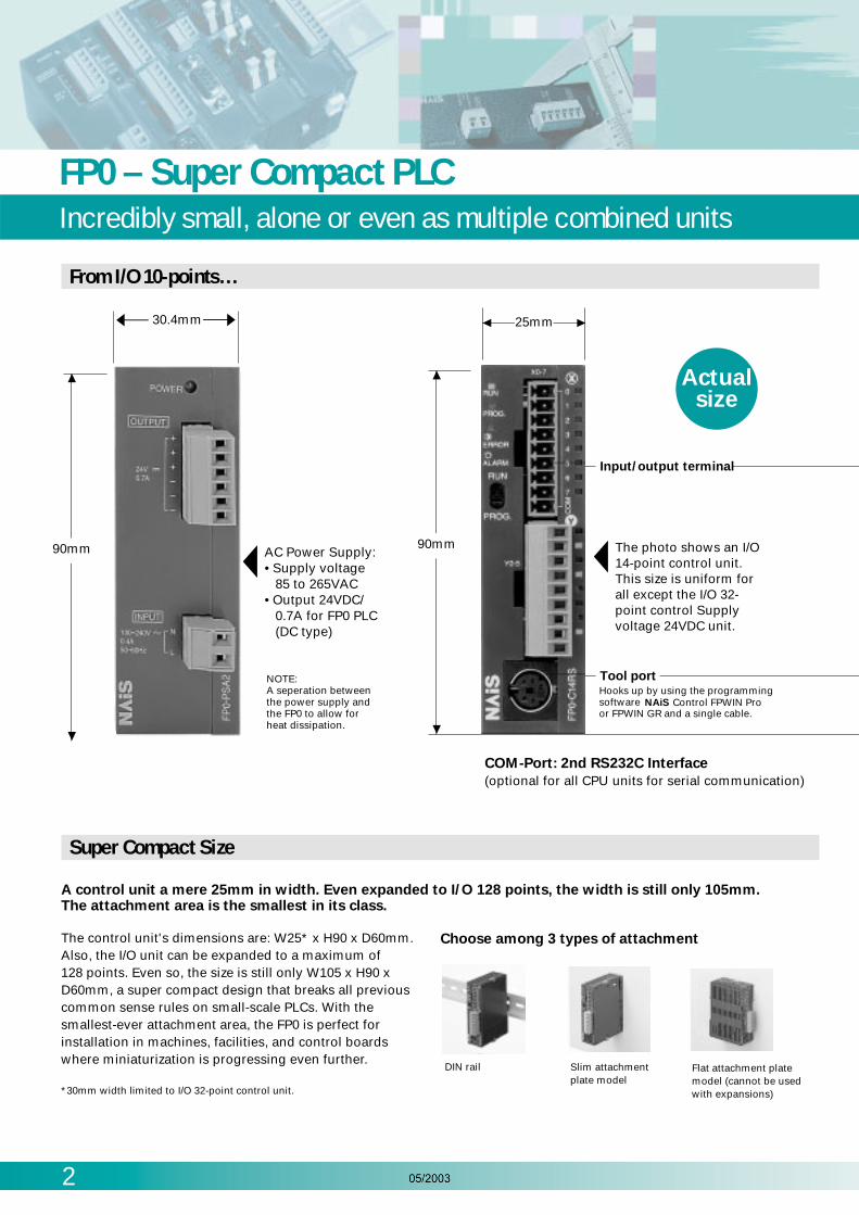
A control unit a mere 25mm in width. Even expanded to I/O 128 points, the width is still only 105mm.The attachment area is the smallest in its class.
The control unit's dimensions are: W25* x H90 x D60mm.Also, the I/O unit can be expanded to a maximum of128 points. Even so, the size is still only W105 x H90 xD60mm, a super compact design that breaks all previouscommon sense rules on small-scale PLCs. With thesmallest-ever attachment area, the FP0 is perfect forinstallation in machines, facilities, and control boardswhere miniaturization is progressing even further.
*30mm width limited to I/O 32-point control unit.
Choose among 3 types of attachment
DIN rail Slim attachmentplate model
Flat attachment platemodel (cannot be usedwith expansions)
Input/output terminal
Tool portHooks up by using the programmingsoftwareor FPWIN GR and a single cable.
25mm
90mm The photo shows an I/O 14-point control unit. This size is uniform for all except the I/O 32-point control Supply voltage 24VDC unit.
NAiS Control FPWIN Pro
Actualsize
From I/O 10-points…
Super Compact Size
COM-Port: 2nd RS232C Interface
(optional for all CPU units for serial communication)
90mm AC Power Supply:• Supply voltage 85 to 265VAC• Output 24VDC/ 0.7A for FP0 PLC (DC type)
NOTE:A seperation between the power supply and the FP0 to allow for heat dissipation.
30.4mm
Either 10 Points or the Maximum of 128 PointsYou save this much space!
3
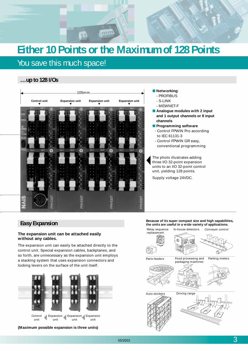
The expansion unit can be attached easilywithout any cables.
The expansion unit can easily be attached directly to thecontrol unit. Special expansion cables, backplanes, and so forth, are unnecessary as the expansion unit employsa stacking system that uses expansion connectors andlocking levers on the surface of the unit itself.
Because of its super compact size and high capabilities, the units are useful in a wide variety of applications.
Relay sequence replacement
In-house detectors Conveyer control
Parts feeders Food processing and packaging machines
Parking meters
Auto-stockers Driving range
Easy Expansion
…up to 128 I/Os
Controlunit
Expansionunit
Expansionunit
Expansionunit
(Maximum possible expansion is three units)
Control unit Expansion unit Expansion unit Expansion unit
105mm
The photo illustrates adding three I/O 32-point expansion units to an I/O 32-point control unit, yielding 128 points.
Supply voltage 24VDC.
Networking:- PROFIBUS- S-LINK- MEWNET-F
Analogue modules with 2 input
and 1 output channels or 8 input
channels
Programming software
- Control FPWIN Pro accordingto IEC 61131-3
- Control FPWIN GR easy,conventional programming

4
FP0 CPU UnitsA rich line-up of both single and combined units
= +
= +
= +
= +
= +
+
+
= + +
= + +
= + + +
= + + +
22Input 12 Output 10
14Input 8 Output 6
8Input 4 Output 4
26Input 14 Output 12
10Input 6 Output 4
16Input 8 Output 8
30Input 16 Output 14
14Input 8 Output 6
16Input 8 Output 8
34Input 18 Output 16
10Input 6 Output 4
16Input 8 Output 8
8Input 4 Output 4
38Input 20 Output 18
14Input 8 Output 6
16Input 8 Output 8
8Input 4 Output 4
42Input 22 Output 20
10Input 6 Output 4
16Input 8 Output 8
16Input 8 Output 8
46Input 24 Output 22
14Input 8 Output 6
16Input 8 Output 8
16Input 8 Output 8
54Input 28 Output 26
14Input 8 Output 6
16Input 8 Output 8
16Input 8 Output 8
8Input 4 Output 4
( )Total numberof I/O points ( )Control unit ( )Expansion unit 1
X20~/Y20~ ( )Expansion unit 2X40~/Y40~ ( )Expansion unit 3
X60~/Y60~= + + +
62Input 32 Output 30
14Input 8 Output 6
16Input 8 Output 8
16Input 8 Output 8
16Input 8 Output 8
Control Units
A maximum of 3 expansion units can be added to the control unit. (Combining relay output types and transistor output typesis also possible. In this event, the maximum number of I/O points when using a relay output type control panel is 110.)
10 pointsInput
6 points
FP0-C10RSA FP0-C10CRSA
with 2nd RS232C
FP0-C14CRSA
with 2nd RS232C
FP0-C16PA (PNP)
FP0-C16TA (NPN)
FP0-C32PA (PNP)
FP0-C32TA (NPN)
FP0-C16CPA (PNP)
FP0-C16CTA (NPN)
with 2nd RS232C
FP0-C32CPA (PNP)
FP0-C32CTA (NPN)
with 2nd RS232C
FP0-C14RSA
Output4 points
10 pointsInput
6 pointsOutput4 points
14 pointsInput
8 pointsOutput6 points
14 pointsInput
8 pointsOutput6 points
16 pointsInput
8 pointsOutput8 points
16 pointsInput
8 pointsOutput8 points
32 pointsInput
16 pointsOutput
16 points
32 pointsInput
16 pointsOutput
16 points
AC Power Supply
FP0-PSA2
Input85 to 265VAC
Terminal type
Output24VDC/0.7A
S-LINK CPU
FP0-SL1
S-LINK master
for up to 128 I/Os
Control Unit 10k
FP0-T32C
32 pointsInput
16 points
FP0-T32CPA (PNP)
FP0-T32CTA (NPN)with 2nd RS232C
Output16 points
This advanced FP0 CPU
offers additional features:
10,000 stepsprogram memory
Battery backed RAM
Real-time clock
16383 wordsdata register
Expansion combinations
Combinations with relay output type – Examples
Relay output type Transistor output type

FP0 Expansion UnitsChoose the number of I/O points to suit the application
5
Digital I/O Units
FP0-E16RSA FP0-E8XA FP0-E16XAFP0-E8RSA
FP0-E8YRSA
8 pointsInput
8 points
16 pointsInput
16 points
8 pointsInput
4 points
Option:
Output 8 points
Output4 points
16 pointsInput
8 pointsOutput8 points
FP0-E8YPA (PNP)
FP0-E8YTA (NPN)
FP0-E16YPA (PNP)
FP0-E16YTA (NPN)
FP0-E16PA (PNP)
FP0-E16TA (NPN)
FP0-E32PA (PNP)
FP0-E32TA (NPN)
8 pointsInput
8 points
16 pointsInput
8 pointsOutput8 points
16 pointsOutput
16 points
32 pointsInput
16 pointsOutput
16 points
Analogue I/O Units Thermocouple Units Networking Units
8 points3 points
Input 8 points
FP0-A80A
• Analogue input: 10V, 0 – 5V, 0 – 20mA
• Analogue output: 10V, 0 – 20mA
• Resolution: 12 bits
• Analogue input: 10V, 100mV0 – 5V, 0 – 20mA
• Resolution: 12 bits
4 points
Input4 points
FP0-TC4 FP0-TC8
8 points
Input8 points
• K, J, T, R type thermocouples canbe used
• Resolution: 0.1°C• Accuracy: 0.8°C (R type: 3°C)• Temperature range: -100 to 1500°C
Input 2 points
FP0-A21A
Output 1 pointPROFIBUS
FP0-DPS2
(DP Slave)
MEWNET-F
FP0-IOL
(MEWNET-F Slave)
Combinations with transistor output type – Examples
= +
= +
= +
= +
= +
+
+
= + +
= + +
= + + +
+
= + + +
48Input 24 Output 24
32Input 16 Output 16
16Input 8 Output 8
16Input 8 Output 8
32Input 16 Output 16
64Input 32 Output 32
32Input 16 Output 16
32Input 16 Output 16
80Input 40 Output 40
32Input 16 Output 16
32Input 16 Output 16
16Input 8 Output 8
16Input 8 Output 8
32Input 16 Output 16
32Input 16 Output 16
96Input 48 Output 48
32Input 16 Output 16
32Input 16 Output 16
32Input 16 Output 16
16Input 8 Output 8
32Input 16 Output 16
32Input 16 Output 16
112Input 56 Output 56
32Input 16 Output 16
32Input 16 Output 16
32Input 16 Output 16
16Input 8 Output 8
( )Total numberof I/O points ( )Control unit ( )Expansion unit 1
X20~/Y20~ ( )Expansion unit 2X40~/Y40~ ( )Expansion unit 3
X60~/Y60~= + + +
16Input 8 Output 8
128Input 64 Output 64
32Input 16 Output 16
32Input 16 Output 16
32Input 16 Output 16
32Input 16 Output 16
Transistor output typeRelay output type Input only type

6
FP0 – Impressive CapabilitiesHigh specifications for both speed and capacity
0.9µs per basic instruction. Pulse catch and interrupt input functions meet the need for high-speed response.
High-speed executionExecution speed of 0.9µs per basic instruction. 500 steps program yields a scanning time of 1ms, which means the FP0boosts the fastest processing time among the products of this class.• Internal processing in the FP0
Large capacity
Pulse catch functionCan read pulses as short as 50µs, which greatly facilitatessensor input.• Pulse catch function
Interrupt input functionAccurate processing, unaffected by scan time• Interrupt input function
I/Orefresh
Programexecution
I/Orefresh
Programexecution
1 scan
I/Orefresh
Programexecution
Internal processing in the FP0
I/Orefresh
Programexecution
I/Orefresh
Programexecution
Sensor inputsignal
Cannotread.
Lengtheningof sensor
input signal
Canread!
With pulse catch function
Internal processing in the FP0
I/Orefresh
Programexecution
I/Orefresh
Programexecution
Interruptprogram
Interrupt input
Interrupt program executed wheninterrupt input enters.
Capacity with 5K and 10K memory size. Also, ample capacity for internal devices. Easily suited to even themost complicated applications. (I/O 32-point type only.)
A top-class large 5K and 10K program capacity housed within a compact body. Furthermore, data capacity for internaldevices like the data register is also ample. The unit's high performance is even suited to complicated controls and controlswith multiple amounts of data.
I/O 10-point, 14-point, 16-point typeControl unit typeI/O 32-point type
Program size
Internal relays
Timers/Counters
Data registers
2 720 steps
1 660 words
5 000 steps
6 144 words
1 008 points
144 points
FP0-T32 CP/T
10 000 steps
16 383 words
FP0 – Impressive CapabilitiesFP0 functions
7
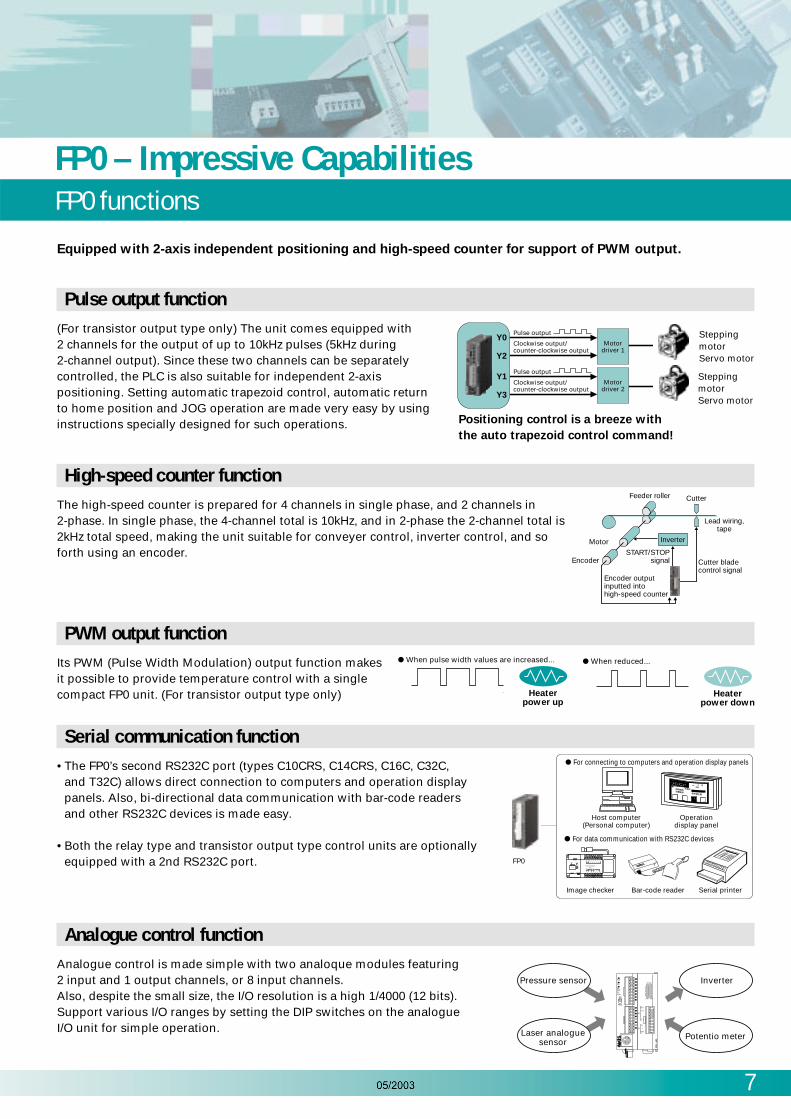
Equipped with 2-axis independent positioning and high-speed counter for support of PWM output.
Pulse output function(For transistor output type only) The unit comes equipped with2 channels for the output of up to 10kHz pulses (5kHz during2-channel output). Since these two channels can be separatelycontrolled, the PLC is also suitable for independent 2-axispositioning. Setting automatic trapezoid control, automatic returnto home position and JOG operation are made very easy by usinginstructions specially designed for such operations. Positioning control is a breeze with
the auto trapezoid control command!
Y0
Y2
Motordriver 1
Pulse output
Clockwise output/counter-clockwise output
Y1
Y3
Motordriver 2
Pulse output
Clockwise output/counter-clockwise output
High-speed counter functionThe high-speed counter is prepared for 4 channels in single phase, and 2 channels in2-phase. In single phase, the 4-channel total is 10kHz, and in 2-phase the 2-channel total is2kHz total speed, making the unit suitable for conveyer control, inverter control, and soforth using an encoder.
PWM output function Its PWM (Pulse Width Modulation) output function makesit possible to provide temperature control with a singlecompact FP0 unit. (For transistor output type only)
Feeder roller
Lead wiring,tape
Cutter
Encoder
MotorSTART/STOP
signal
Inverter
Cutter bladecontrol signal
Encoder outputinputted intohigh-speed counter
Serial communication function• The FP0’s second RS232C port (types C10CRS, C14CRS, C16C, C32C,
and T32C) allows direct connection to computers and operation displaypanels. Also, bi-directional data communication with bar-code readersand other RS232C devices is made easy.
• Both the relay type and transistor output type control units are optionallyequipped with a 2nd RS232C port.
Host computer(Personal computer)
Operationdisplay panel
FP0
For connecting to computers and operation display panels
For data communication with RS232C devices
Image checker Bar-code reader Serial printer
RS-232C
POWER READY
MODEA
B
C
KEY PAD
CAMERA MONITOR
COM COM D2 D4 D6 D8 D9
FLASH D1 D3 D5 D7 READY
MICRO-IMAGECHECKER
M100
Matsuhita Electronic Works, Ltd.24VDC
START ACK IN1 IN3 IN5
COM COM IN2 IN4 COM
Heaterpower up
When pulse width values are increased...
When reduced...
Analogue control functionAnalogue control is made simple with two analoque modules featuring2 input and 1 output channels, or 8 input channels.Also, despite the small size, the I/O resolution is a high 1/4000 (12 bits).Support various I/O ranges by setting the DIP switches on the analogueI/O unit for simple operation.
PROG.
RUNALARM
ERROR
PROG
RUNPressure sensor
Laser analoguesensor
Inverter
Potentio meter
MODE
OFF ON
V 0
INI 0
COM
FP
0 -
A21
OUT
I 1
V
I
12345
SteppingmotorServo motor
SteppingmotorServo motor
power up
Heaterpower down
When reduced...

8
FP0 CommunicationSerial interfaces and modem compatible
Programming interface TOOL Port (also for communication)In Computer Link mode, this port offers access to the entire FP0 memory area. For example during data exchange betweena host PC running SCADA software and an FP0 PLC, the Windows® based MEWNET-DDE Server assumes total control ofthe communications protocol (MEWTOCOL.COM). Therefore the user can disregard the allocation of data ranges andtransfer parameters, because there is no additional programming required. The programmer is thus free to concentrateexclusively on the project application requirements.
Communication Interface COM Port(flexible with two modes of operation, Computer Link and General Purpose)In addition to the Computer Link communication possibilities described above, the optional integrated RS232C COM Port inthe FP0 CPU module (types FP0-C10CRS, FP0-C14CRS, FP0-C16C, FP0-C32C and FP0-T32C) offers flexible programming i.e.General Purpose. In this configuration it is possible to realise communication connections with different RS232C peripheraldevices, e.g. Bar Code Readers, slave devices, printers, measurement sensors or telecommunication transmitters, etc.
Communication Interface COM-PortFreely programmable RS232C interface for CPU modules type FP0-C10CRS,FP0-C14CRS, FP0-C16C, FP0-C32C and FP0-T32C
Communication – Simple and efficient via two serial interfaces: TOOL port and COM port (RS232C interface).
Programming Interface TOOL Port For programming, and additionally Master/Slave communication, usingMEWTOCOL COM (Matsushita protocol)
Modem compatible
Even modem communicationfunction is built into this compactbody. Using a single telephone line,programming maintenance can becarried out in remote facilities. WithC-NET, multiple FP0 units can beconnected.
Programming maintenance is possible in remote areas with a single phone line and communicationin “RUN” mode.
Connection can be made witha program connector.
FP Modem-EU
Publicphone line
Cable/adapter
CablePublicphone lineCable
Connection to multiple PCs is also possible, using a C-NET adapter.
Dedicated RS232Cstraight cable (AFB85843)
C-NET adapter S2 type(AFP15402)
C-NET adapter for PC(AFP8536)
2-line cable (RS485)(VCTF0.75X2C)
Up to 32 separatelocations can beconnected(max. 1.2km)
FP0FP0
1:1 communication 1:N communication
FP Modem-EU FP Modem-EU FP Modem-EU

FP0 CommunicationEasier maintenance than ever before
9
Maintenance saving
Overwrite function in RUN mode
It is possible to overwrite a program while the FP0 is running, such as during program debugging and startupadjustments.
Backup battery unnecessary
The program memory uses EEPROM. The program and device contents can be stored without a backup battery, andeven programming for a machine builder is safe.
Password function
A password function can be set in order to change a program. Limited to people authorized to make program changes,protection can be guaranteed better than ever.
Input/output verification LED
Every unit is equipped with LED I/O indicators, housed within a compact body. Input/output status can be verifiedat a glance.
Terminal type can beplugged straight in withoutresorting to crimping (madeby Phoenix Contact Co.).Can handle wires from0.3 to 1.25mm2.
Compatible models
FP0-10RS, C14RS, E8RS, E16RS
Unit connectors can be usedwith 16-point and 32-pointunits. Due to the loose-wiring,pressure contact type design,wiring is easy without theneed for insulation. (MIL-C-83503)
Compatible models
FP0-C16T/C16P/C16CT/C16CP, C32T/C32P/C32CT/C32CP, E16T/E16P, E32T/E32P,FP0-T32CP/T32CT
Program memory uses EEPROM. In addition, programs can be changed even in RUN mode!
Simple installationComes with either terminal block or connector. Either type is easy to connect to wiring by simply removing the terminal section.
Terminal block MIL connector

10
FP0 PROFIBUS DP Slave or Remote I/O UnitFor cost effective control of distributed field device
The FP0 DPS2 can operate either as a DP slave module or as a remote I/Osystem to which different decentralised inputs and outputs can beconnected. A DIP switch can be used to switch between the two modes:
Mode 1:
DP-Slave module. Connect the FP0 or FP∑ (Sigma) CPU + expansionmodules to the PROFIBUS network.
Mode 2:
Remote I/O. Connect up to three expansion modules without CPU to thePROFIBUS network.
In Remote I/O mode the unit can be connected to any PLC which offers aPROFIBUS communication interface, making it totally independent ofNAiS PLCs.
Item Description
Type designation
PROFIBUS standards complied with
FP0 DP Slave unit, Ord. No. FP0DPS2
EN 50170, DIN 19245 Part 1 and Part 3
Baud rates9.6 / 19.2 / 93.75 / 187.5 / 500 / 1,500 / 3,000 / 6,000 / 12,000 Kbaud
automatic baud rate detection
Range of adresses that can be set 0..125
PROFIBUS connection
Configuration
9-pin D-sub connector
2 words input / 2 words output, up to 6 words input / 6 words output if no other expansion is connected
Remote I/O, max. 3 FP0 expansion unit
FP0 communication Via FP0 system bus
Power supply 24VDC (21.6VDC … 26.4VDC)
Max. power consumption 100mA
FP0-DPS Specifications
DP-SlaveRemote I/O
PLC
(Master)
PLC
(Slave)
Remote I/O
(Slave)
FP0 DP Slave FP∑ (Sigma) DP Slave
DP Slave Remote I/OConfiguration with digital I/Oup to 96 transistor I/O orup to
48 relay I/O are possible
DP Slave Remote I/O Configurationwith analogue I/O 6 In/3 Out or24 analogue inputs or up to 24
thermocouple inputs are possible
FP2 DP or FMS Master
Special developed software tools ensureeasy configuration and start-up ofPROFIBUS products.

11
FP0 S-LINK UnitConnects directly to the S-LINK for reduced wiring
Makes use of the T-shaped connectability of the S-LINK and itsreduced wiring and simple installation for reduced size of thecontrol board. Supports the control S-LINK I/O unit with 64 inputpoints and 64 output points. Allows the use of up to threeexpansion units for efficient I/O wiring.
Direct connection for reduced wiring
FP0S-LINK Control unitW30 × H90 × D60
Maximum length: 200mMax. 128 points
T-branch multidrop wiring
2 signal wires2 power
supply wires
Features1. Small size of only W30 x H90 x D60 mm.
Makes use of the T-shaped connectability of the S-LINK for reduced wiring and reduced sizeof the control panel.
2. Controls 64 input points and 64 output points.
Able to control up to 128 points for S-LINK-related devices.
3. Allows simultaneous use of expansion units.
Similar to other FP0 units, up to three expansion units can be used for efficient I/O wiring.
4. A wide range of I/O modules allow manifold customer-oriented network layouts
Item Description
Power supply 24VDC
Power Supply Specification
Item Description
Program block-edit during RUN
Constant scan
Adjustable input timefiltering
Clock/Calendar function
Available
Available
Not available
None
Other Built-in Functions
Item Description
Number of I/O points
Expansion
S-LINK block: 64 input points, 64 output points (fixed)
Max. 3 units Expansion section:Max. 96 points
Operation speed 0.9µs/step
Internal memory EEPROM
Memory capacity 5k steps
Memory Internal relayof Timer/Counterexecution Data register
1,008 points
144 points in total
6,144 words
Performance Specifications
Item Description
Pulse catch/Interrupt input
Volume input
High-speed Counter
None
Analogue I/O Available by adding analogue I/O unit
None
None
Pulse output None
RS232C port1 ch is equipped.3P terminal blocks (made byPhoenix Contact Co.)
Applicable Functions
Item Description
Remote I/O
Inter-PLC link
Computer link
Modem connection
Control unit functions as S-LINKmaster station.Available as a slave station ofMEWNET-F by adding I/O link unit.
Not available
Linkable with tool port orRS232C port
Available, Type with RS232Cport can also send data.
Applicable Network
FP0-SL1

12
FP0 MEWNET-F UnitNetworking units
The FP0 can be used as a slave station for MEWNET-F (remote I/O system) by adding I/O link unit
MEWNET-F is a reduced-wiring remote I/O system that connects PLCslocated separately and I/O slave stations with 2-core cabling. By adding anI/O link unit to the FP0, you can link master station PLC and FP0 inputs andoutputs via the network.
Item Description
Communication method
Synchronous system
Two-wire, half duplex transmission
Start stop synchronous system
Transmission line 2-wire cable (Twisted-pair cable or equivalent to VCTF 0.75 mm2 x 2C)
Transmission distance (Total distance)
Max. 700m per port (using twisted pair cable)Max. 400m per port (using VCTF cable)
Transmission speed (Baud rate) 0,5Mbit/s
Number of control I/O point per an I/O link unit
64 points(Input: 32 points and Output: 32 points)
Remote I/O map allocation
Interface
Transmission error check
32X/32Y
Conforms to RS485
CRC (Cyclic Redundancy Check) method
FP0-IOL Link Unit Specifications
By using C-NET, you can use multiple FP0s as data collection terminals
By using the C-NET network and exclusiveadapters, you can connect multiple FP0s bymulti-drop connection with 2-wire cables.You can use computers for separate controlor have network terminals for a centralizedmanagement system.
MEWNET-F
C-NET
FP2 (Master station)
FP0 (Slave station) FP0 (Slave station) FP0 (Slave station)
Twisted pair cable or VCTF
FP0-IOL FP0-IOL FP0-IOL
C-NETadapter
AC 100 to 200V 24V DC
: AFP8536: AFP8532
C-NETadapterS2 type
(AFP15402)
Max. 32 unitsMax. 1,200 m
FP0
( )
MEWNET-F SlaveFP0-IOL

The FP0-TC4 and FP0-TC8 thermocouple units are suitable for userfriendly temperature acquisition using standard thermocouples withhigh precision.
Up to three units can be added to each control unit, enablingtemperature control of up to 24 channels.
The temperature data obtained using the thermocouple is converted tothe digital value to be read into the FP0 control unit.
Standard types of thermocouples can be used: K, J, T and R
3 temperature measurement ranges are available:-100.0 to +500.0 (Thermocouple types: K and J)-100.0 to +400.0 (Thermocouple type : T)- 0.0 to +1500.0 (Thermocouple type : R)
The temperature data measured using the sensor is converted todegrees Celsius or degrees Fahrenheit inside the Thermocouple Unit.
The converted data (°C or °F) is averaged, so that even unstable inputsignals can be properly read.
Broken thermocouples can be detected.
FP0 Thermocouple Input Expansion UnitsEnable high precision temperature control at low cost
13
Temperature control
FP0 TC88 channels
FP0 TC44 channels
Item Specification
Input point
Input range
Up to 8 channels per unit (The number of input points can be changed 2, 4, 6 and 8 channels are available)
Thermocouple types K, J -100.0°C to 500.00°C
Thermocouple types T -100.0°C to 400.00°C
Thermocouple types R 0°C to 1500.00°C
Resolution 0.1°C
Sampling cycle *5
300ms: when using 2 channels for an input points *4
500ms: when using 4 channels for an input points *4
700ms: when using 6 channels for an input points *4
900ms: when using 8 channels for an input points *4
Accuracy
Range for K and J (-100°C to 500°C): 0.8°CRange for T (-100°C to 400°C): 0.8°CRange for R (0°C to 99.9°C): 3°C
(100°C to 299.9°C): 2.5°C(300°C to 1500°C): 2°C
Input Impedance
Insulation method
more than 1MΩ
- between thermocouple input terminals and control Unit internal circuits Photo-coupler insulation/DC-DC insulation- between thermocouple input terminal channels PhotoMos relay insulation
FP0-TC4 and FP0-TC8 specifications

14
Analogue Signal ProcessingFP0 Analogue Units FP0-A21 / FP0-A80
Parts Terminology and Dimensions
Analogue I/O mode switch
Analogue I/O Terminal
Power Supply Connector for Analogue I/O Unit
60mm
25mm
FP0-A21
90mm
Analogue I/O mode switch
Analogue I/O Terminal
Power Supply Connector for Analogue I/O Unit
60mm
25mm
FP0-A80
90mm
Analogue unit position
Expansion unit 1
Expansion unit 2
Expansion unit 3
addressinput output
WX2, WX3 WY2
WX4, WX5
WX6, WX7
WY4
WY6
Multimode A/D, D/A conversion.Voltage, current and temperature selectable
2 analogue inputs (FP0-A21)/8 analogue inputs (FP0-A80):± 10V, 0 to 5V, 0 to 20mA, -100°C to 1000°C
1 analogue output (FP0-A21):± 10V, 0 to 20mA
High resolution: 12-bit
High conversion speed (FP0-A21):Inputs: 1ms/ch (thermocouple: 560ms)Output: 500ms
PID instruction with auto tuning (FP0-A21)
Screw terminal connection
Features
Analogue I/O signals can be processed with the FP0 analogue units. Each FP0 CPU supports up to 3 FP0 analogue units.Combination with digital and analogue expansion units is freely allowed.
Highest performance is offered with 12-bit resolution and high-speed A/D, D/A conversion. The multimode FP0 analogueunit can be configured via the DIP switches on the front side into the required analogue ranges. Communication with theFP0 CPU unit is achieved via the expansion bus. The expansion bus is automatically connected after the FP0 analogue unitis connected to the FP0 CPU unit.

Analogue Signal ProcessingFP0 Analogue Units FP0-A21 / FP0-A80
15
Item Description
Rated operating voltage
Operating voltage range
24VDC
21.6 to 26.4VDC
Rated current consumption 100mA or less
Ambient temperature 0°C to + 5°CStorage temperature -20°C to + 70°CSize 90 x 25 x 60mm
Weight 100g
Order No. FP0-A21 (2 inputs / 1 output), FP0-A80 (8 inputs)
General specifications
Item Description
Number of channels
Output signal selectable
1 channel / unitVoltage mode -10V to +10VCurrent mode 0 to 20mA
Digital input
Resolution
0 to 20mA: K 0 to K 4000 (H 0000 to H 0FA0)-10V to +10V: K -2000 to K+2000 (H F830 to H 07D0)12 bits (1/4000)
Conversion speed 500ms
Overall accuracy 1% for full-scale (0 to 55°C), 0.6% for full-scale (at 25 °C)
Output impedance Voltage mode: less than 0.50ΩMaximum output current Voltage mode: +/- 10mA
Allowable output load resist-ance Current mode: less than 300Ω
Insulation
FP0 output address
(*5) The address varies depending on the position of the analogue unit. (WY2, WY4 or WY6).
Optical coupler insulation between analogue output terminal and FP0 internal circuitDC/DC converter insulation between analogue output terminal and analogue I/O unit external power supplyDC/DC converter insulation between analogue output terminal and analogue input terminal16 output contact points (WY2) (*5)
Analogue output specification (FP0-A21)
Item
Product
Description
FP0-A21 FP0-A80
Number of channels
Input range selectable( 2 CH)
2 channel s/ unit 8 channels / unit
-100 to +100mV / 0 to 5V / -10V to +10V
0 to 20mA
–
–
2ms / channel
–
–
Voltage mode 0 to 5V / -10V to +10V
Digital output
Resolution
Conversion speed
Overall accuracy
Input impedance
Maximum input
Insulation
FP0 input address
(*1) K means decimal constants.(*2) Reference temperature → Reference point is start point.(*3) Reference temperature → Reference point is end point.(*4) The address varies depending on the position of the analogue unit. (WX2/3, WX4/5 or WX6/7)
Current mode 0 to 20mA
Thermocouple mode K, J, T type thermocoupleK up to 1000°C or -100°C to terminal temperature (selectable)J up to 750°C or -100°C to terminal temperature (selectable)T up to 350°C or -100°C to terminal temperature (selectable)
0 to 5V / 0 to 20mA: K 0 to K 4000 (H 0000 to H 0FA0) (*1)-10 to +10V (-100 to +100mV): K -2000 to K +2000 (HF830 to H07D0)Thermocouple: The value of broken wire detection is K 20000.
For plus: K temperature of terminal (*2) to K 1000 (Unit is Celsius)For minus: K-100 to K temperature of terminal (*3) (Unit is Celsius)
12 bits (1/4000)Voltage/current mode: 1ms/ channelThermocouple mode: 560ms/ channelVoltage/current mode: 1% for full-scale (0 to 55°C), 0.6% for full-scale (at 25°C)Thermocouple mode: Offset error (0 to 55°C), 2% for full-scale (K-type)
2.7% for full-scale (J-type)5.8% for full-scale (T-type)
linearity error (0 to 55%): 1% for full scaleVoltage mode: 1M ohm or moreCurrent mode: 250ohmVoltage mode: +/- 15VCurrent mode: +30mAOptical coupler insulation between analogue input terminal and FP0 internal circuit(No insulation between analogue inputs)DC/DC converter insulation between analogue input terminal and analogue I/O unit external power supplyDC/DC converter insulation between analogue input terminal and analogue output terminal
32 input contact points: First 16 points analogue input CH0 data (WX2) (*4)Last 16 points analogue input CH1 data (WX3) (*4)
32 input contact points: First 16 points analogue input
CH0, 2,4,6 data (WX2) (*4)Last 16 points analogue input
CH1,3,5,7 data (WX3) (*4)
Analogue input specification
16
FP0-PSA2 / FP-PS24-050E24VDC Power Supplies
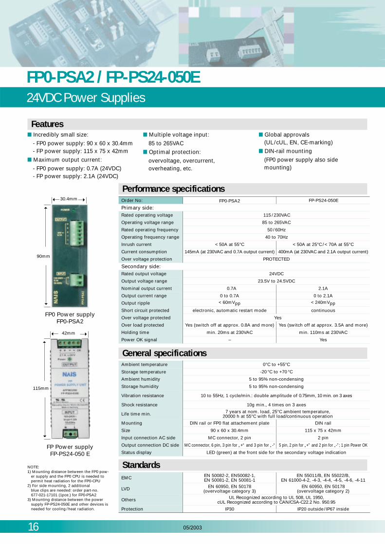
Incredibly small size:
- FP0 power supply: 90 x 60 x 30.4mm- FP power supply: 115 x 75 x 42mm
Maximum output current:
- FP0 power supply: 0.7A (24VDC)- FP power supply: 2.1A (24VDC)
Multiple voltage input:
85 to 265VAC Optimal protection:
overvoltage, overcurrent, overheating, etc.
Global approvals
(UL/cUL, EN, CE-marking) DIN-rail mounting
(FP0 power supply also sidemounting)
Primary side:Rated operating voltage
Operating voltage range
Rated operating frequency
Operating frequency range
Inrush current
Current consumption
Over voltage protection
Secondary side:Rated output voltage
Output voltage range
Nominal output current
Output current range
Output ripple
Short circuit protected
Over voltage protected
Over load protected
Holding time
115 / 230VAC
85 to 265VAC
50 / 60Hz
40 to 70Hz
< 50A at 55°C < 50A at 25°C / < 70A at 55°C145mA (at 230VAC and 0.7A output current)
PROTECTED
24VDC
23.5V to 24.5VDC
0.7A
0 to 0.7A< 60mVpp
electronic, automatic restart mode
Yes
Yes (switch off at approx. 0.8A and more)
min. 20ms at 230VAC
Order No: FP0-PSA2 FP-PS24-050E
400mA (at 230VAC and 2.1A output current)
2.1A
0 to 2.1A< 240mVpp
continuous
Yes (switch off at approx. 3.5A and more)
min. 110ms at 230VAC
Power OK signal – Yes
Performance specifications
Ambient temperature
Storage temperature
Ambient humidity
Storage humidity
Vibration resistance
Shock resistance
Life time min.
Mounting
Size
Input connection AC side
Output connection DC side
Status display
0°C to +55°C-20 °C to +70 °C
5 to 95% non-condensing
5 to 95% non-condensing
10 to 55Hz, 1 cycle/min.: double amplitude of 0.75mm, 10 min. on 3 axes
10g min., 4 times on 3 axes
7 years at nom. load, 25°C ambient temperature, 20000 h at 55°C with full load/continuous operation
DIN rail or FP0 flat attachement plate
90 x 60 x 30.4mm
MC connector, 2 pin
MC connector, 6 pin, 3 pin for „+“ and 3 pin for „-“
DIN rail
115 x 75 x 42mm
2 pin
5 pin, 2 pin for „+” and 2 pin for „-”; 1 pin Power OK
LED (green) at the front side for the secondary voltage indication
General specifications
EMC
LVD
Others
Protection
EN 50082-2, EN50082-1, EN 50081-2, EN 50081-1
EN 55011/B, EN 55022/B, EN 61000-4-2, -4-3, -4-4, -4-5, -4-6, -4-11
EN 60950, EN 50178 (overvoltage category 3)
EN 60950, EN 50178 (overvoltage category 2)
UL Recognized according to UL 508, UL 1950, cUL Recognized according to CAN/CSA-C22.2 No. 950.95
IP30 IP20 outside/ IP67 inside
StandardsNOTE:
1) Mounting distance between the FP0 pow-er supply and the FP0 CPU is needed topermit heat radiation for the FP0-CPU
2) For side mounting, 2 additional blue clips are needed: order part-no. 677-021-17101 (1pce.) for FP0-PSA2
3) Mounting distance between the powersupply FP-PS24-050E and other devices isneeded for cooling / heat radiation.
FP0 Power supply
FP0-PSA2
FP Power supply
FP-PS24-050 E
30.4mm
90mm
42mm
115mm
Features

FP0 SeriesSpecification tables
17
FP0 Specifications
General SpecificationsItem Description
Rated operating voltage 24 VDCOperating voltage range 21.6 to 26.4 VDC
Allowable no voltage time 10 points, 14 points type 5ms (at 21.6 V), 10ms (at 24 V)16 points, 32 points, S-LINK type 10ms (at 21.6 V / 24 V)
Ambient temperature 0¡C to +55¡CStorage temperature —20¡C to +70¡CAmbient humidity 30 to 85% RH (Non-condensing)Storage humidity 30 to 85% RH (Non-condensing)
Breakdown voltageBetween input/output terminals and power/ground terminals: 500V AC for 1 minute (for the relay output type, 1500V AC for 1 minute)Between input terminals and output terminals: 500V AC for 1 minute (for the relay output type, 1500V AC for 1 minute)
Insulation resistanceBetween input/output terminals and power/ground terminals: Over 100 MΩ (using a 500V DC megger)Between input terminals and output terminals: Over 100 MΩ (using a 500V DC megger)
Vibration resistance 10 to 55Hz, 1 sweep/min., double amplitude of 0.75mm, 10min. on 3 axesShock resistance 98m/s 2 or more, 4 times on 3 axesNoise immunity 1,000 V(p-p) with pulse widths 50ns and 1ms (using a noise simulator)Operating condition Free from corrosive gasses and excessive dust
Type of control unitC10 series
(Relay output type only)C14 series
(Relay output type only)C16 series
(Transistor output type only)C32 series
(Transistor output type only) S-LINK typeT32 series
(Transistor output type only)Programming method / Control method Relay symbol/Cyclic operation
Number ofI/O points
No expansion(control unit only)
Total: 10(Input: 6, Output: 4)
Total: 14(Input: 8, Output: 6)
Total: 16(Input: 8, Output: 8)
Total: 32(Input: 16, Output: 16)
S-LINK section: max.128points(Input: 64, Output: 64)
Total: 32(Input:16, Output: 16)
W/expansion 1*Same type of control and expansion units Max. 58 Max. 62 Max. 112 Max. 128
Expansion section:max.96 points
Max. 128
W/expansion 2*Mix type of relay and transistor units Max. 106 Max. 110 Max. 112 Max. 128 Max. 128
Program memory EEPROM (No back-up battery required)Program capacity 2.7K steps 5K steps 10K stepsKinds ofinstruction
Basic 83High-level 115
Operation speed (central value/step) 0.9ms (Basic instruction)
Memory forexecution
RelayIntermal relay (R) 1,008 pointsTimer/Counter (T/C) 144 points
Memoryarea
Data register (DT) 1,660 words 6,144 words 16,384 wordsIndex register(IX,IY) 2 words
Master control relay (MCR) 32 pointsNumber of labels (JMP and LOOP) 64 labels 255 labelsDifferential points Unlimited number of pointsNumber of step ladder 128 stages 704 stagesNumber of subroutines 16 subroutines 100 subroutines
Specialfunctions
High speed counter 1 phase/4 points (10kHz in total) or 2 phases / 2 points (2kHz in total)* Not available Available (same as 32 points series)
Pulse output Not available2 points (10 kHz* in total),enable to control 2channels individually* Not available Available
(same as 32 points series)
PWM output Not available 0.15Hz to 1kHz Not available Available (same as 32 points series)
Pulse catch input/interrupt input 6 points(with high speed counter) Not available Available (same as 32 points series)
Interrupt program 7 programs (external 6 points, internal 1 point) 1 program (internal 1 point) Available (same as 32 points series)
Periodical interrupt 0.5ms to 30sConstant scan Available
RS232C portOne RS232C port is mounted on each of the models FP0- C10CR, C14CR,C16CT, C16CP, C32CT, C32CP, T32CT, T32CP and SL1 type (3P terminal block)Transmission speed (Baud rate) :300 to 19200bits/s, 3m Communication method: half duplexTransmission distance: 3m
Maintenance
Memoryback up
Program and system register Stored program and system register in EEPROM
Operationmemory
Stored x ed area in EEPROMCounter: 4 pointsInternal relay: 32 pointsData register: 8 words
Stored x ed area in EEPROMCounter: 16 pointsInternal relay: 128 pointsDate register: 32 words
Backup is provided by secondary battery. The holding range for the timers, counters, internal relays, and data regis-ters are speci ed with the programming tool.
Self-diagnosis functions Watchdog timer, program syntax checking, etc.Clock/calender function Not available AvailableOther functions Runtime editing, password setting
* For the limitations while operating units, see the manual.
18
FP0 SeriesSpecification tables
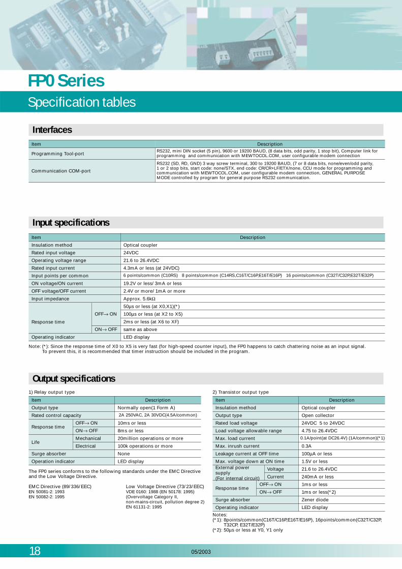
Item Description
Programming Tool-port
Communication COM-port
RS232, mini DIN socket (5 pin), 9600 or 19200 BAUD, (8 data bits, odd parity, 1 stop bit), Computer link forprogramming and communication with MEWTOCOL.COM, user configurable modem connection
RS232 (SD, RD, GND) 3 way screw terminal, 300 to 19200 BAUD, (7 or 8 data bits, none/even/odd parity, 1 or 2 stop bits, start code: none/STX, end code: CR/CR+LF/ETX/none, CCU mode for programming andcommunication with MEWTOCOL.COM, user configurable modem connection, GENERAL PURPOSEMODE controlled by program for general purpose RS232 communication.
Note: (*): Since the response time of X0 to X5 is very fast (for high-speed counter input), the FP0 happens to catch chattering noise as an input signal.To prevent this, it is recommended that timer instruction should be included in the program.
Notes:(*1): 8points/common(C16T/C16P,E16T/E16P), 16points/common(C32T/C32P,
T32CP, E32T/E32P)(*2): 50µs or less at Y0, Y1 only
The FP0 series conforms to the following standards under the EMC Directiveand the Low Voltage Directive.
EMC Directive (89/336/EEC) Low Voltage Directive (73/23/EEC)EN 50081-2: 1993 VDE 0160: 1988 (EN 50178: 1995)EN 50082-2: 1995 (Overvoltage Category II,
non-mains-circuit, pollution degree 2)EN 61131-2: 1995
Interfaces
Item
Insulation method Optical coupler
Rated input voltage 24VDC
Operating voltage range 21.6 to 26.4VDC
Rated input current 4.3mA or less (at 24VDC)
Input points per common 6 points/common (C10RS) 8 points/common (C14RS,C16T/C16P,E16T/E16P) 16 points/common (C32T/C32P,E32T/E32P)
ON voltage/ON current 19.2V or less/ 3mA or less
OFF voltage/OFF current 2.4V or more/ 1mA or more
Input impedance Approx. 5.6kΩ
Response time
OFF→ ON
50µs or less (at X0,X1)(*)
100µs or less (at X2 to X5)
2ms or less (at X6 to XF)
ON→ OFF same as above
Operating indicator LED display
Description
Input specifications
Item
1) Relay output type
Output type Normally open(1 Form A)
Rated control capacity
OFF→ ON
ON→ OFF
Mechanical
Electrical
2A 250VAC, 2A 30VDC(4.5A/common)
Response time10ms or less
8ms or less
Life20million operations or more
100k operations or more
Surge absorber None
Operation indicator LED display
Description
Output specifications
Item
2) Transistor output type
Insulation method Optical coupler
Output type Open collector
Rated load voltage 24VDC 5 to 24VDC
Load voltage allowable range 4.75 to 26.4VDC
Max. load current 0.1A/point(at DC26.4V) (1A/common)(*1)
Max. inrush current 0.3A
Leakage current at OFF time 100µA or less
Max. voltage down at ON time
Response time
1.5V or less
OFF→ ON 1ms or less
ON→ OFF 1ms or less(*2)
Surge absorber Zener diode
Operating indicator LED display
Description
External powersupply(For internal circuit)
Voltage 21.6 to 26.4VDC
Current 240mA or less

19
Control FPWIN ProPLC programming software conforming to IEC61131-3
FP Programmer II Ver. 2
Programming cableAFC8513D
Programming cableAFC8523
Programmingsoftware
Connect with RS232C cable
FP0
The most important highlights at a glance: Reuse of ready made functions and function blocks saves time for programming and debugging 5 Programming Languages (Instruction List, Ladder Diagram, Structured Text, Function Block Diagram,
Sequential Function Chart) 4 Standard Libraries (IEC Standard Library, Matsushita Library, NC Tool Library, Pulsed Library) Program Organisation Units, Task and Project management
features provide solid structure. Fewer errors through defined data types and encapsulation Online Monitoring and Diagnostics Modem Communication for remote programming,
service, and diagnostics Password protection with different security levels IEC 61131-3 protects your investments for the future
Control FPWIN Pro – Programming
Control FPWIN Pro is the Matsushita programming software according to the international standard IEC 61131-3.Control FPWIN Pro works with the FP0 as well as any FP series programmable controller. Also, since the tool port is anRS232C, connection to a PC is easy – it only requires a single cable. No converter or adapter is required.

20
Control FPWIN ProPLC programming software for easy operation
Program status display
Function instruction list
Classified by type, functioncommands can be selectedfrom the displayed list.(Simple help included.)
Menu
Program display
Tool bar
Access often-usedfunctions using icons.
Function bar
Provides informationregarding commandinput and confirmation,on-line/off-lineselection and PLCmode selection.
I/O comment edit function
Successive I/O comments canbe input for each device type.Data from Excel and otherapplications can be copied andpasted via the clipboard.
Status display
Displays informationconcerning PLC usageenvironment and settings,and detailed informationwhen an error occurs.
FP Series programming software for Windows.
1. To facilitate operation on site, a mouse is not required for input, search, write, monitor and timer edit operations.Everything can be accomplished with a keyboard alone.
2. Standard Windows operations, such as copy and paste, are included.3. Supports all FP series machines. Software created with NPST-GR Ver. 3 or 4 can also be used.4. Inherits convenient functions developed for NPST-GR.
Features
OS
Required hard disk capacity
Recommended CPU
Recommended installed memory
Recommended screen resolution
Recommended display colors
Windows 95/98/NT (Ver. 4.0 or later)/XP
At least 30MB
Pentium 100MHz or higher
32MB or more
800 x 600 or higher
High Color (16-bit or higher)
Usage environment Applicable PLC types*All products on the market are supported.
All FP series types are supported:FP∑ Sigma, FP0, FP-e, FP1, FP2, FP2SH, FP3, FP10SH, FP-M
Note: FPWIN GR Vers. 2.2 or later is needed to program the FP-e
Control CommX, PCWAY, OPC ServerVisualisation software for ready made or customised solutions
21
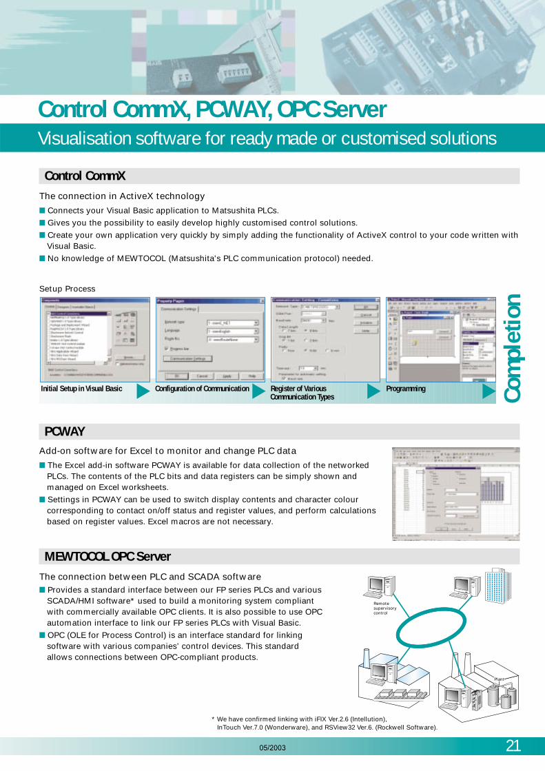
The connection in ActiveX technology
Connects your Visual Basic application to Matsushita PLCs. Gives you the possibility to easily develop highly customised control solutions. Create your own application very quickly by simply adding the functionality of ActiveX control to your code written with
Visual Basic. No knowledge of MEWTOCOL (Matsushita's PLC communication protocol) needed.
Control CommX
Add-on software for Excel to monitor and change PLC data
The Excel add-in software PCWAY is available for data collection of the networkedPLCs. The contents of the PLC bits and data registers can be simply shown andmanaged on Excel worksheets.
Settings in PCWAY can be used to switch display contents and character colourcorresponding to contact on/off status and register values, and perform calculationsbased on register values. Excel macros are not necessary.
PCWAY
The connection between PLC and SCADA software
Provides a standard interface between our FP series PLCs and variousSCADA/HMI software* used to build a monitoring system compliantwith commercially available OPC clients. It is also possible to use OPCautomation interface to link our FP series PLCs with Visual Basic.
OPC (OLE for Process Control) is an interface standard for linkingsoftware with various companies’ control devices. This standardallows connections between OPC-compliant products.
MEWTOCOL OPC Server
Initial Setup in Visual Basic Configuration of Communication Register of Various Programming
Setup Process
Communication Types
Com
plet
ion
Remotesupervisorycontrol
PlantPlantPlant
* We have confirmed linking with iFIX Ver.2.6 (Intellution),InTouch Ver.7.0 (Wonderware), and RSView32 Ver.6. (Rockwell Software).

22
FP0 Control and Expansion UnitsProducts and order numbers
Expansion units
Notes: A power cable (order number AFP0581) is enclosed with the control unit and the relay output type upgrade units (Transistor output type upgrade units do
not require a power cable). Two Phoenix terminals (9-pin) are needed with the relay output type terminal type. A 2.5mm width screwdriver is needed for the wiring.
Have ready a dedicated terminal screwdriver (order number AFP0806: Phoenix order number SZS0, 4 X 2.5 compatible), or equivalent. A loose-wiring pressure socket and contact (2 pins with order numbers FP0-C16T/P, E16T/P, and 4 pins with order numbers FP0-C32T/P, E32T/P) are needed
with the transistor output type. A loose-wiring connector pressure contact tool (order number AXY52000) is needed for the wiring.
Relay output type
Transistor output type
Relay output type Input only type
Transistor output type
10 points
Input 6 points
Terminal type
Order number: FP0-C10RSA
Terminal type
Order number: FP0-C10CRSAwith 2nd RS232C interface
Terminal type
Order number: FP0-C14CRSAwith 2nd RS232C interface
PNP/NPN output type
Order number: FP0-C16PA (PNP)FP0-C16TA (NPN)
PNP/NPN output type
Order number: FP0-C32PA (PNP)FP0-C32TA (NPN)
PNP/NPN output type
Order number: FP0-C32CPA (PNP)FP0-T32CPA (PNP, 10K)
FP0-C32CTA (NPN)FP0-T32CTA (NPN, 10K)
with 2nd RS232Cinterface
Terminal type
Order number: FP0-C14RSA
Output 4 points10 points
Input 6 points Output 4 points14 points
Input 8 points Output 6 points14 points
Input 8 points Output 6 points
16 points
Input 8 points Output 8 points16 points
Input 8 points Output 8 points32 points
Input 16 points Output 16 points32 points
Input 16 points Output 16 points
8 points
Input 4 points
Terminal type relay
Order number: FP0-E8RS
Terminal type relay
Order number: FP0-E16RS
Order number: FP0-E16X
PNP/NPN output type
Order number: FP0-E8YPA (PNP)
FP0-E8YTA (NPN)
PNP/NPN output type
Order number: FP0-E16PA (PNP)
FP0-E16TA (NPN)
PNP/NPN output type
Order number: FP0-E16YPA (PNP)
FP0-E16YTA (NPN)
PNP/NPN output type
Order number: FP0-E32PA (PNP)
FP0-E32TA (NPN)
Order number: FP0-E8X
Output 4 points16 points
Input 8 points Output 8 points8 points
Input 8 points16 points
Input 16points
8 points
Output 8 points16 points
Output 16 points16 points
Input 8 points Output 8 points32 points
Input 16 points Output 16 points
PNP/NPN output type
Order number: FP0-C16CPA (PNP)FP0-C16CTA (NPN)with 2nd RS232Cinterface
Control units

FP0 Analogue and Networking UnitsProducts and order numbers
23
3 points
Input 2 points
Terminal type
Order number: FP0-A21A
Terminal type
Order number: FP0-A80A
Output 1 point8 points
Input 8 points
4 points
Input 4 points
Terminal type
Order number: FP0-TC4
Terminal type
Order number: FP0-TC8
8 points
Input 8 points
Input85 to 265VAC
Terminal type
Order number: FP0-PSA2
Output24V DC / 0.7A
Input85 to 265VAC
Terminal type
Order number: FP-PS24-050E
Output24VDC / 2.1A
PROFIBUS
PROFIBUSDP-Slave or Remote I/O
Order number: FP0-DPS2
MEWNET-F
MEWNET-FSlave
Order number: FP0-IOL
S-LINK CPU
S-LINKMaster
Order number: FP0-SL1
Networking units
Analogue units
AC power supply FP Memory Loader
Read or write programs fromor to a PLC
Order number: AFP8670

24
Programming and SoftwareProducts and order numbers
FP0
When using a Handy Programmer
FP Programmer II Ver. 2
Order number: AFP1114V2
Programming cable<for use with FP programmers>
Order number: AFC8523
D-SUB 15 pin-M5 mini-DIN connector (length: 3m)
Programming cable for PC software D-SUB 9 pin-M5 mini-DIN connector (length: 3m)
Commercial PC FP0
Using PC software
Order number: AFC8513D
ControlControl
Made in GermanyMade in Germany
Matsushita Electric Works, Ltd.1995-20001995-2000
Matsushita Electric Works, Ltd.
FPWIN GRFPWIN GRVer.3Ver.3
ControlControl
Made in GermanyMade in Germany
Matsushita Electric Works(Europe)AG1995-20001995-2000
Matsushita Electric Works(Europe)AG
FPWIN ProFPWIN ProVer.4Ver.4
Control FPWIN ProEnglish, German, French Italian,Spanish, Japanese menu selectable.According to IEC 61131-3 Standard
order number: small version for MINI-PLC only
(FP0, FP-e, FPM, FP1, FP∑ Sigma)• FPWINPROSEN (English manual)• FPWINPROSDE (German manual)• FPWINPROSFR (French manual)
full version for all FP-Series PLCs• FPWINPROFEN (English manual)• FPWINPROFDE (German manual)• FPWINPROFFR (French manual)
Programming tools
Programming software:
Other Software Tools
Using PC Software
When using a Handy Programmer
Control FPWIN GREnglish, Italian, Spanish,menu selectable
order number: full version for all FP-Series PLCs:
• FPWINGR F2 (English manual)
PCWAY
order numer:
AFW10011 (Software+ Printer port dongle)
AFW10031 (Software+ USB port dongle)
Control CommX
order numer:
AFW20011 (Software+ Printer port dongle)
AFW20031 (Software+ USB port dongle)
MEWTOCOLOPC Server
order numer:
AFPS01510 (1 license)
AFPS01515 (5 licenses)
AFPS01516 (10 licenses)
AccessoriesProducts and order numbers
25
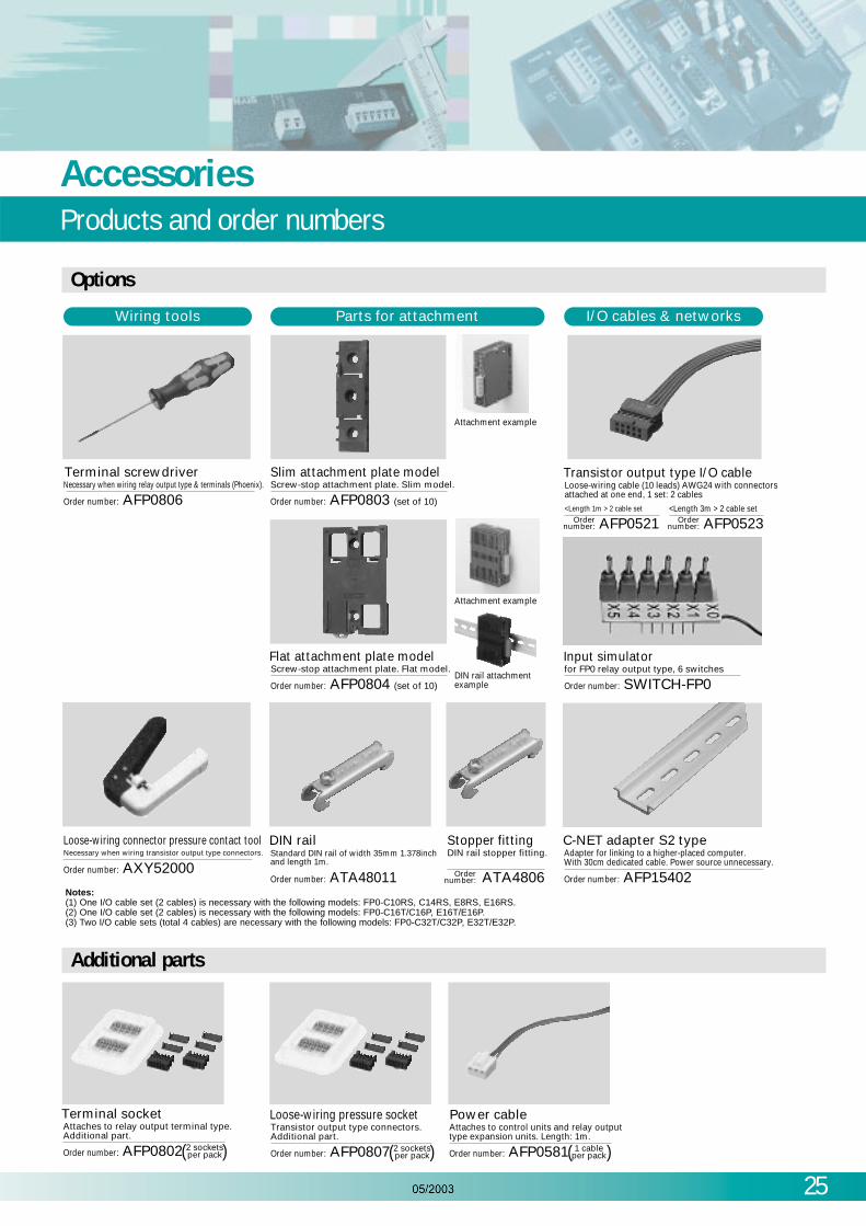
Notes:(1) One I/O cable set (2 cables) is necessary with the following models: FP0-C10RS, C14RS, E8RS, E16RS.(2) One I/O cable set (2 cables) is necessary with the following models: FP0-C16T/C16P, E16T/E16P.(3) Two I/O cable sets (total 4 cables) are necessary with the following models: FP0-C32T/C32P, E32T/E32P.
Terminal screwdriverNecessary when wiring relay output type & terminals (Phoenix).
Attachment example
Wiring tools Parts for attachment I/O cables & networks
Order number: AFP0806
Slim attachment plate modelScrew-stop attachment plate. Slim model.
Order number: AFP0803 (set of 10)
Attachment example
DIN rail attachment example
Flat attachment plate modelScrew-stop attachment plate. Flat model.
<Length 1m > 2 cable set <Length 3m > 2 cable set
Transistor output type I/O cableLoose-wiring cable (10 leads) AWG24 with connectorsattached at one end, 1 set: 2 cables
Order number: AFP0804 (set of 10)
Input simulatorfor FP0 relay output type, 6 switches
Order number: SWITCH-FP0
Loose-wiring connector pressure contact toolNecessary when wiring transistor output type connectors.
Order number: AXY52000Order number: ATA48011
C-NET adapter S2 typeAdapter for linking to a higher-placed computer.With 30cm dedicated cable. Power source unnecessary.
Order number: AFP15402
DIN railStandard DIN rail of width 35mm 1.378inchand length 1m.
Ordernumber:
Stopper fittingDIN rail stopper fitting.
ATA4806Ordernumber:
AFP0521 Ordernumber: AFP0523
Terminal socketAttaches to relay output terminal type.Additional part.
Order number: AFP0802 2 socketsper pack( )
Loose-wiring pressure socketTransistor output type connectors.Additional part.
Order number: AFP0807 2 socketsper pack( )
Power cableAttaches to control units and relay output type expansion units. Length: 1m.
Order number: AFP0581 1 cableper pack( )
Options
Additional parts

26
FP0 SeriesTechnical data
Type of unit Part numberCurrent Consumption
Supply to the power supply connector of the control unit *1 Supply to the power supply connector of the expansion and intelligent units *2
Control unit
C10 series, C14 series 100mA or lessC16 series 40mA or lessC32 series, T32 series 60mA or lessSL1 150mA or less
Expansion unit
E8X 10mA or lessE8YRS 10mA or less 100mA or lessE8YT, E8YP 15mA or lessE8R 20mA or less 50mA or lessE16R 20mA or less 100mA or lessE16X 20mA or lessE16T, E16P, E16YT, E16YP 25mA or lessE32T, E32P 40mA or less
Intelligent unit
A21 20mA or less 100mA or lessA80 20mA or less 60mA or less
PROFIBUS unit FP0-DPS 10mA or less 100mA or lessFP programmer AFP1114V2 50mA or lessC-NET adapter AFP15402 50mA or less
IOL 30mA or less 40mA or less
TC4 25mA —
TC8 25mA —
Notes)*1 The current consumption from the power supply connector block of the control unit. Calculate the total current consumption based on the combination of the units.*2 The current consumption from the power supply connector block of the expansion unit and intelligent unit.
TypeItembeing compared
New 32-point type(Part No. FP0-T32CT, FP0-T32CP)
Conventional 32-pointtype (FP0-C32CT/-C32CP)
Program capacity 10k steps 5k stepsData register 16,384 words 6,144 wordsSpecial data register From DT90000 From DT9000
Memorybackup
Program and systemregister EEPROM EEPROM
Operation memory
The operation memory is backed up using built-in chargeable (secondary) battery, so the hold type memory areas can be speci ed using the programming tools.Memory areas which can be speci ed:Timers/counters <T/C>, Internal relays <R>, Data registers <DT>
Areas which are held if the power supply fails are x ed, and are retained by the EEPROM.Number of points/words of the x ed hold areas in the various memoriesCounters <C>: 16 points, Internal relays <R>: 128 points, Data registers <DT>: 32 words
Reading andwriting forEEPROM
F12 (ICRD) and P13 (PICWT) instructions
Available 6,144 words Available 6,144 words
Programmingtools
Software Available Available
FP programmer II Not available Available
Current consumption list
Similarities and differences between the 10k steps type FP0 and the conventional 32-point type
FP0 Product OverviewOrder numbers
27
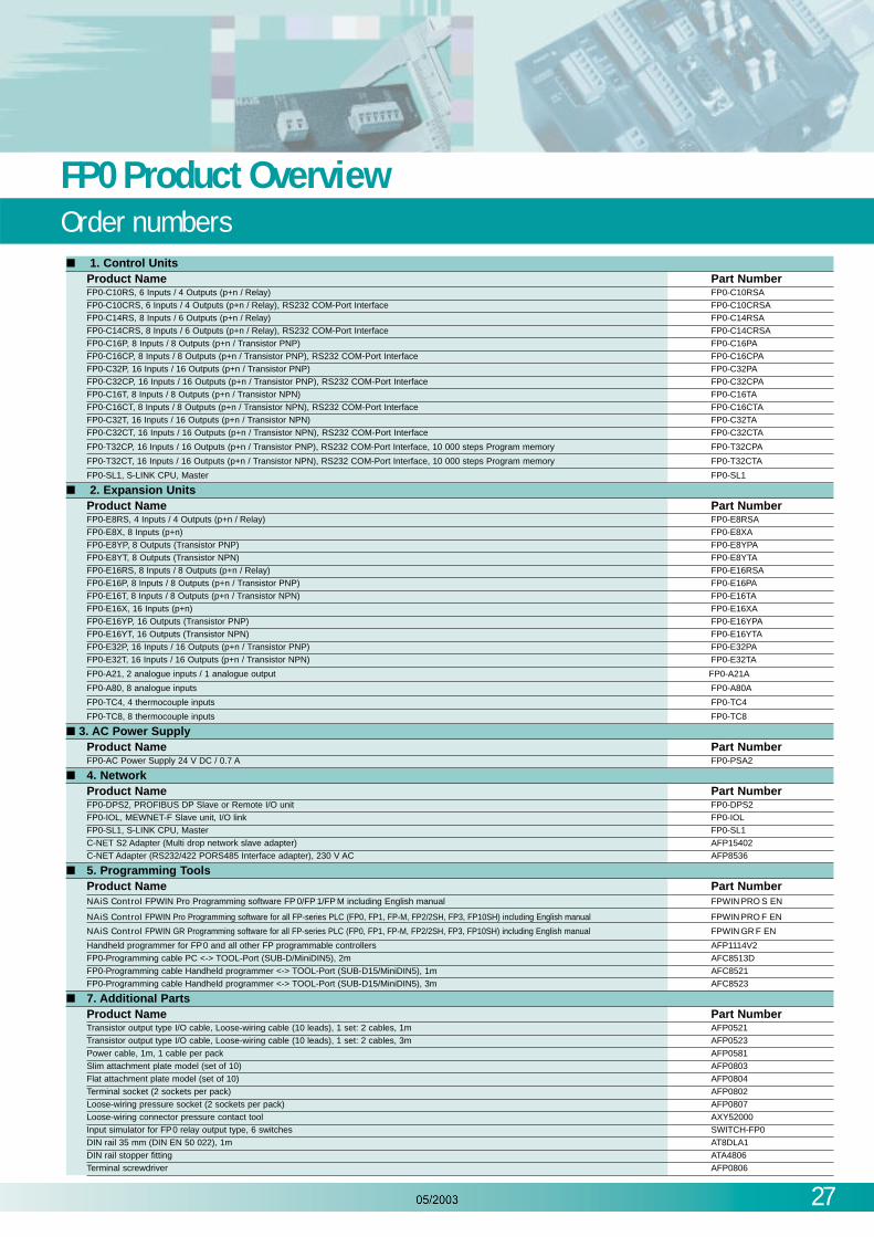
1. Control UnitsProduct Name Part NumberFP0-C10RS, 6 Inputs / 4 Outputs (p+n / Relay) FP0-C10RSAFP0-C10CRS, 6 Inputs / 4 Outputs (p+n / Relay), RS232 COM-Port Interface FP0-C10CRSAFP0-C14RS, 8 Inputs / 6 Outputs (p+n / Relay) FP0-C14RSA
FP0-C14CRS, 8 Inputs / 6 Outputs (p+n / Relay), RS232 COM-Port Interface FP0-C14CRSAFP0-C16P, 8 Inputs / 8 Outputs (p+n / Transistor PNP) FP0-C16PAFP0-C16CP, 8 Inputs / 8 Outputs (p+n / Transistor PNP), RS232 COM-Port Interface FP0-C16CPA
FP0-C32P, 16 Inputs / 16 Outputs (p+n / Transistor PNP) FP0-C32PAFP0-C32CP, 16 Inputs / 16 Outputs (p+n / Transistor PNP), RS232 COM-Port Interface FP0-C32CPAFP0-C16T, 8 Inputs / 8 Outputs (p+n / Transistor NPN) FP0-C16TA
FP0-C16CT, 8 Inputs / 8 Outputs (p+n / Transistor NPN), RS232 COM-Port Interface FP0-C16CTAFP0-C32T, 16 Inputs / 16 Outputs (p+n / Transistor NPN) FP0-C32TAFP0-C32CT, 16 Inputs / 16 Outputs (p+n / Transistor NPN), RS232 COM-Port Interface FP0-C32CTA
FP0-T32CP, 16 Inputs / 16 Outputs (p+n / Transistor PNP), RS232 COM-Port Interface, 10 000 steps Program memory FP0-T32CPA
FP0-T32CT, 16 Inputs / 16 Outputs (p+n / Transistor NPN), RS232 COM-Port Interface, 10 000 steps Program memory FP0-T32CTA
FP0-SL1, S-LINK CPU, Master FP0-SL1
2. Expansion UnitsProduct Name Part NumberFP0-E8RS, 4 Inputs / 4 Outputs (p+n / Relay) FP0-E8RSAFP0-E8X, 8 Inputs (p+n) FP0-E8XA
FP0-E8YP, 8 Outputs (Transistor PNP) FP0-E8YPAFP0-E8YT, 8 Outputs (Transistor NPN) FP0-E8YTAFP0-E16RS, 8 Inputs / 8 Outputs (p+n / Relay) FP0-E16RSAFP0-E16P, 8 Inputs / 8 Outputs (p+n / Transistor PNP) FP0-E16PA
FP0-E16T, 8 Inputs / 8 Outputs (p+n / Transistor NPN) FP0-E16TAFP0-E16X, 16 Inputs (p+n) FP0-E16XAFP0-E16YP, 16 Outputs (Transistor PNP) FP0-E16YPA
FP0-E16YT, 16 Outputs (Transistor NPN) FP0-E16YTAFP0-E32P, 16 Inputs / 16 Outputs (p+n / Transistor PNP) FP0-E32PAFP0-E32T, 16 Inputs / 16 Outputs (p+n / Transistor NPN) FP0-E32TA
FP0-A21, 2 analogue inputs / 1 analogue output FP0-A21A
FP0-A80, 8 analogue inputs FP0-A80A
FP0-TC4, 4 thermocouple inputs FP0-TC4
FP0-TC8, 8 thermocouple inputs FP0-TC8
3. AC Power SupplyProduct Name Part NumberFP0-AC Power Supply 24 V DC / 0.7 A FP0-PSA2
4. NetworkProduct Name Part NumberFP0-DPS2, PROFIBUS DP Slave or Remote I/O unit FP0-DPS2
FP0-IOL, MEWNET-F Slave unit, I/O link FP0-IOLFP0-SL1, S-LINK CPU, Master FP0-SL1C-NET S2 Adapter (Multi drop network slave adapter) AFP15402C-NET Adapter (RS232/422 PORS485 Interface adapter), 230 V AC AFP8536
5. Programming ToolsProduct Name Part NumberNAiS Control FPWIN Pro Programming software FP 0/FP 1/FP M including English manual FPWIN PRO S EN
NAiS Control FPWIN Pro Programming software for all FP-series PLC (FP0, FP1, FP-M, FP2/2SH, FP3, FP10SH) including English manual FPWIN PRO F EN
NAiS Control FPWIN GR Programming software for all FP-series PLC (FP0, FP1, FP-M, FP2/2SH, FP3, FP10SH) including English manual FPWIN GR F EN
Handheld programmer for FP0 and all other FP programmable controllers AFP1114V2FP0-Programming cable PC <-> TOOL-Port (SUB-D/MiniDIN5), 2m AFC8513D
FP0-Programming cable Handheld programmer <-> TOOL-Port (SUB-D15/MiniDIN5), 1m AFC8521FP0-Programming cable Handheld programmer <-> TOOL-Port (SUB-D15/MiniDIN5), 3m AFC8523
7. Additional PartsProduct Name Part NumberTransistor output type I/O cable, Loose-wiring cable (10 leads), 1 set: 2 cables, 1m AFP0521Transistor output type I/O cable, Loose-wiring cable (10 leads), 1 set: 2 cables, 3m AFP0523
Power cable, 1m, 1 cable per pack AFP0581Slim attachment plate model (set of 10) AFP0803Flat attachment plate model (set of 10) AFP0804Terminal socket (2 sockets per pack) AFP0802Loose-wiring pressure socket (2 sockets per pack) AFP0807Loose-wiring connector pressure contact tool AXY52000Input simulator for FP0 relay output type, 6 switches SWITCH-FP0DIN rail 35 mm (DIN EN 50 022), 1m AT8DLA1DIN rail stopper fitting ATA4806Terminal screwdriver AFP0806
Copyright © 2003 • Printed in Germany4093 eu en 05/03
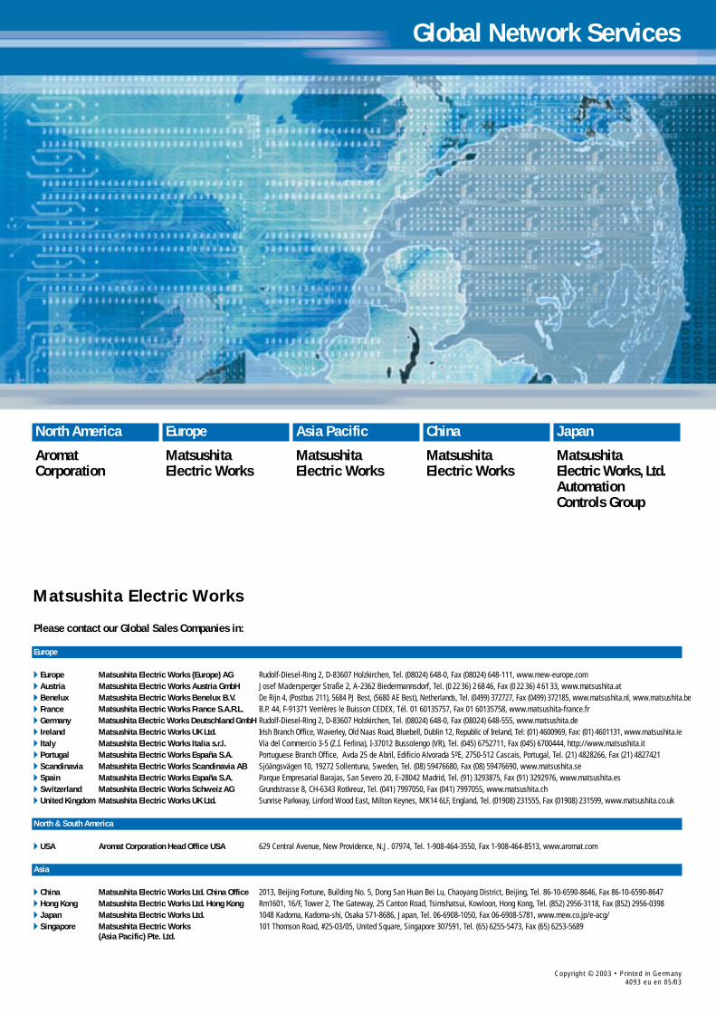
Please contact our Global Sales Companies in:
Europe
Europe Matsushita Electric Works (Europe) AG Rudolf-Diesel-Ring 2, D-83607 Holzkirchen, Tel. (08024) 648-0, Fax (08024) 648-111, www.mew-europe.com Austria Matsushita Electric Works Austria GmbH Josef Madersperger Straße 2, A-2362 Biedermannsdorf, Tel. (0 22 36) 2 68 46, Fax (0 22 36) 4 61 33, www.matsushita.at Benelux Matsushita Electric Works Benelux B.V. De Rijn 4, (Postbus 211), 5684 PJ Best, (5680 AE Best), Netherlands, Tel. (0499) 372727, Fax (0499) 372185, www.matsushita.nl, www.matsushita.be France Matsushita Electric Works France S.A.R.L. B.P. 44, F-91371 Verrières le Buisson CEDEX, Tél. 01 60135757, Fax 01 60135758, www.matsushita-france.fr Germany Matsushita Electric Works Deutschland GmbH Rudolf-Diesel-Ring 2, D-83607 Holzkirchen, Tel. (08024) 648-0, Fax (08024) 648-555, www.matsushita.de Ireland Matsushita Electric Works UK Ltd. Irish Branch Office, Waverley, Old Naas Road, Bluebell, Dublin 12, Republic of Ireland, Tel: (01) 4600969, Fax: (01) 4601131, www.matsushita.ie Italy Matsushita Electric Works Italia s.r.l. Via del Commercio 3-5 (Z.I. Ferlina), I-37012 Bussolengo (VR), Tel. (045) 6752711, Fax (045) 6700444, http://www.matsushita.it Portugal Matsushita Electric Works España S.A. Portuguese Branch Office, Avda 25 de Abril, Edificio Alvorada 5-ºE, 2750-512 Cascais, Portugal, Tel. (21) 4828266, Fax (21) 4827421 Scandinavia Matsushita Electric Works Scandinavia AB Sjöängsvägen 10, 19272 Sollentuna, Sweden, Tel. (08) 59476680, Fax (08) 59476690, www.matsushita.se Spain Matsushita Electric Works España S.A. Parque Empresarial Barajas, San Severo 20, E-28042 Madrid, Tel. (91) 3293875, Fax (91) 3292976, www.matsushita.es Switzerland Matsushita Electric Works Schweiz AG Grundstrasse 8, CH-6343 Rotkreuz, Tel. (041) 7997050, Fax (041) 7997055, www.matsushita.ch United Kingdom Matsushita Electric Works UK Ltd. Sunrise Parkway, Linford Wood East, Milton Keynes, MK14 6LF, England, Tel. (01908) 231555, Fax (01908) 231599, www.matsushita.co.uk
North & South America
USA Aromat Corporation Head Office USA 629 Central Avenue, New Providence, N.J. 07974, Tel. 1-908-464-3550, Fax 1-908-464-8513, www.aromat.com
Asia
China Matsushita Electric Works Ltd. China Office 2013, Beijing Fortune, Building No. 5, Dong San Huan Bei Lu, Chaoyang District, Beijing, Tel. 86-10-6590-8646, Fax 86-10-6590-8647 Hong Kong Matsushita Electric Works Ltd. Hong Kong Rm1601, 16/F, Tower 2, The Gateway, 25 Canton Road, Tsimshatsui, Kowloon, Hong Kong, Tel. (852) 2956-3118, Fax (852) 2956-0398 Japan Matsushita Electric Works Ltd. 1048 Kadoma, Kadoma-shi, Osaka 571-8686, Japan, Tel. 06-6908-1050, Fax 06-6908-5781, www.mew.co.jp/e-acg/ Singapore Matsushita Electric Works 101 Thomson Road, #25-03/05, United Square, Singapore 307591, Tel. (65) 6255-5473, Fax (65) 6253-5689
(Asia Pacific) Pte. Ltd.
Matsushita Electric Works
North America
AromatCorporation
Asia Pacific
MatsushitaElectric Works
China
MatsushitaElectric Works
Japan
MatsushitaElectric Works, Ltd.AutomationControls Group
Europe
MatsushitaElectric Works
Global Network Services