fpga implementation of mil-std-1553b bus protocol ... · the data bus connects avionics system...
TRANSCRIPT

International Journal of Science and Research (IJSR) ISSN (Online): 2319-7064
Index Copernicus Value (2013): 6.14 | Impact Factor (2013): 4.438
Volume 4 Issue 7, July 2015
www.ijsr.net Licensed Under Creative Commons Attribution CC BY
FPGA Implementation of MIL-STD-1553B Bus
Protocol Controller for Aircrafts
Siji K.1, Saritha N. R
2
1 1PG Scholar, Embedded Systems, Sree Buddha College of Engineering, Kerala, India
2Assistant Professor, Department of Electronics and Communication, Sree Buddha College of Engineering, Kerala, India
Abstract: Data buses are used in military applications to download information from the aircraft before launching of vehicle and
coordinate information flow during the flight. Initially direct point-to-point wires were used to connect components in avionics systems.
But when the complexity of the systems in the aircrafts began to increase, the wiring became both very complex and heavy. To
overcome these difficulties, US Department of Defence published the 1553 serial data bus standard. MIL-STD-1553B is a widely
popular, standard data bus that has been employed for data transmission in a variety of aerospace and defence systems. The entire
control of the 1553 bus system is associated with in the Bus Controller (BC). The 1553B bus protocol controller is incorporated with a
Manchester encoder and a Manchester decoder. In this work, protocol controller is implemented with the addition of other blocks such
as protocol logic, arbitrator for meeting the demands of the protocol. The proposed system also incorporate memory management and
processor interface logic. Here, the 1553B bus controller is modeled as a finite state machine in VHDL. Finally, all the components
needed for the bus controller is integrated as a single block as a result area of utilization can be reduced. The proposed design is
simulated in ModelSim and implemented onto a Xilinx based FPGA platform.
Keywords: MIL-STD-1553, Bus Controller (BC), VHDL, ModelSim, FPGA.
1. Introduction
The data bus connects avionics system components and
transports information among them in an aircraft. Modern
day avionics systems communicate with others using the
MIL-STD-1553B bus. MIL-STD-1553B, is a military
standard, dual redundant bus which is published by the
United States Department of Defence. It is a time division,
command or response, serial data bus with data rate of
1Mbps [1].
A typical system would consist of two buses, a single bus
controller (BC) and up to 31 addressable remote-terminals
(RT) which interface the bus to the-user sub-systems. MIL-
STD-1553B was designed to offer high integrity, high
reliability data transmission in the modern military
environment [2]. The 1553 data bus uses Manchester II bi-
phase encoding and decoding scheme. Manchester coding
has some advantages like easy error detection, high noise
immunity etc [6]. MIL-STD-1553B bus has higher data
integrity, because of Manchester encoding of data bits. This
thesis aims to design a 1553 data bus controller simulation in
VHDL. The 1553 bus controller is known as the 'heart of the
system' since it controls all the activities in the bus. In this
work the 1553 bus controller with an arbitrator, processor
interface and a protocol controller is designed.
Most significant problem behind the existing bus protocol is
the memory accessing. There may arise conflicts while
accessing memory by both protocol controller and processor.
To overcome this, the proposed system is designed with an
arbitrator. The bus is a twisted shielded pair cable, low
impedance one and terminated with resistors at each end
equal to the characteristic impedance of the cable, which is in
the range of 70 to 85 ohms for 1553B.
1553B military data bus provides two major advantages such
as significant size or weight savings of interconnected
devices and cabling and reduced development and
modification costs with compatible devices.
This paper aims to design a bus protocol controller for MIL-
STD-1553B data bus. The 1553 bus controller is known as
the 'heart of the system' since it controls all the activities in
the bus. The proposed system describes the 1553B bus
protocol controller with an arbitrator, memory management
mechanism and a protocol controller.
The rest of this paper is organized as follows: Section 2
describes the overview of MIL-STD-1553B bus system,
which gives details about the architecture of data bus. The
next section deals with the design considerations of MIL-
STD-1553B bus controller. Section 4 contains the
implementation details of proposed system. Section 5
presents the simulation and results obtained. Section 6
concludes the paper with a set of references.
2. MIL-STD-1553 Overview
2.1 Architecture of 1553 Data Bus
MIL-STD-1553B defines the data bus architecture in which a
maximum of 32 devices can be connected to the 1553B data
bus which is shown in Figure 1. It has a dual-redundant
architecture and extremely low error rate of one word fault
per 10 million words make MIL-STD-1553 a highly reliable
bus. Only a single device is allowed to transmit on the bus at
a given time. Terminals connected in the 1553B data bus has
a master/slave relationship.
The computer that controls all the communication on the bus
and acts as the master is called Bus Controller (BC) [1]. In
Paper ID: SUB157054 2556
International Journal of Science and Research (IJSR) ISSN (Online): 2319-7064
Index Copernicus Value (2013): 6.14 | Impact Factor (2013): 4.438
Volume 4 Issue 7, July 2015
www.ijsr.net Licensed Under Creative Commons Attribution CC BY
addition to initiating all data transfers, the BC must transmit,
receive and coordinate the transfer of information on the data
bus. All information is communicated in command/response
mode, i.e., the BC sends a command to the RTs, which reply
with a response. The BC can control multiple slave
computers which are called Remote Terminals (RT) by
sending commands to them. The remote terminal (RT) is a
device designed to interface various subsystems with the
1553 data bus and provide the sources and sinks of data.
Figure 1: MIL-STD-1553 data bus architecture [6]
There may also be one or more passive Bus Monitors (BM)
deployed on the bus which are only used to monitor or record
the messages on the bus but can’t transmit any messages. As
shown in Figure 1, a maximum of thirty-one remote terminals
can be connected to the bus in addition to the bus controller
[2]. Only the bus controller can initiate a transmission on the
bus. The RT receives and decodes commands from the bus
controller and responds accordingly within the strictly
defined time of 12 microseconds. An RT only performs
transmission or reception of data when instructed to do so by
the BC.
The BC is responsible for directing communications over the
data bus. Although several of the systems connected to the
bus may have the ability to perform the role of BC. Only one
BC is allowed to active at any given time and that only may
issue commands over the data bus. These commands may be
related to the management of the bus or may be oriented
toward data communication to and from subsystems.
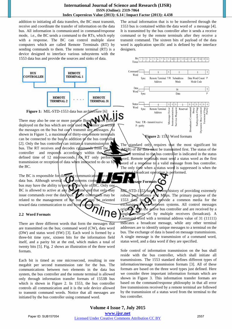
2.2 Word Formats
There are three different words that form the messages that
are transmitted on the bus; command word (CW), data word
(DW) and status word (SW) [3]. Each word is formed by a
three-bit time sync, sixteen bits for the information field
itself, and a parity bit at the end, which makes a total of
twenty bits [5]. Fig. 2 shows an illustration of the three word
formats.
Each bit is timed as one microsecond, resulting in one
megabit per second transmission rate for the bus. The
communications between two elements in the data bus
system, the bus controller and the remote terminal is allowed
only through information transfer formats of 1553B bus
which is shown in Figure 2. In 1553, the bus controller
controls all communication and it is the sole device allowed
to transmit command words. Notice that all messages are
initiated by the bus controller using command word.
The actual information that is to be transferred through the
1553 bus is contained within the data word of a message [4].
It is transmitted by the bus controller after it sends a receive
command or by the remote terminals after they receive a
transmit command. The sixteen bits of payload of the data
word is application specific and is defined by the interface
designers.
Figure 2: 1553 Word formats
The standard only requires that the most significant bit
(MSB) of the data must be transmitted first. The status of the
remote terminal to the bus controller is indicated in the status
word. Remote terminals must send a status word as the first
word of a response to a valid message from bus controller.
The only time when a status word is suppressed is when the
optional broadcast operation is performed.
2.3 Message Formats
MIL-STD-1553 has a proven history of providing extremely
robust performance at 1 Mbps. The primary purpose of the
1553 data bus is to provide a common media for the
exchange of data between systems. All control messages
originate with the active bus controller and are received by a
single receiver or by multiple receivers (broadcast). A
command word with a terminal address value of 31 (11111)
indicates a broadcast message, while any other terminal
addresses are to identify unique messages to a terminal on the
bus. The exchange of data is based on message transmissions.
A single message is the transmission of a command word,
status word, and a data word if they are specified.
Sole control of information transmission on the bus shall
reside with the bus controller, which shall initiate all
transmissions. The 1553 standard defines different types of
information/message transmission formats [3]. All of these
formats are based on the three word types just defined. Here
we consider three important information formats which are
shown in Figure 3. This information transfer formats are
based on the command/response philosophy in that all error
free transmissions received by a remote terminal are followed
by the transmission of a status word from the terminal to the
bus controller.
Paper ID: SUB157054 2557

International Journal of Science and Research (IJSR) ISSN (Online): 2319-7064
Index Copernicus Value (2013): 6.14 | Impact Factor (2013): 4.438
Volume 4 Issue 7, July 2015
www.ijsr.net Licensed Under Creative Commons Attribution CC BY
The bus controller to remote terminal (BC-RT) message is
referred to as the receive command since the remote terminal
is going to receive data [8]. The bus controller outputs a
command word to the terminal defining the subaddress of the
data and the number of data words it is sending. The remote
terminal upon validating the command word and all of the
data words issues its status word within the response time
requirements which is maximum of 12μs.
The remote terminal to bus controller (RT-BC) message is
referred to as a transmit command. The bus controller issues
only a transmit command word to the remote terminal[9].
The terminal, on validating the command word, transmits its
status word followed by the number of data words requested
by the command word. The remote terminal to remote
terminal (RT-RT) command allows a terminal (the data
source) to transfer data directly to another terminal (the data
sink) without going through the bus controller. However, the
bus controller may also collect the data and use them. (This is
sometimes called a RT-RT-M command, since the Bus
Controller monitors the data). The bus controller issues a
command word to the receiving terminal immediately
followed by a command word to the transmitting terminal
[5]. Here, the message shall include the two command words,
the two status words, and the data words.
Notes:
# Inter Message Gap
.... Response Time
Figure 3: 1553 Information transfer formats [3]
3. Design
A 1553B system is composed of a bus controller and one or
more remote terminals, connected by the 1553B serial data
bus. Bus management is accomplished via a strict master-
slave relationship between the BC and RTs. To provide
multiple data paths for redundancy, a mission-critical system
typically utilizes several 1553B buses. All bus transmissions
are accessible to all units connected to the bus, but only one
unit can “speak” at a time. The BC initiates all bus transfers
by sending a command word to individual RTs, and each RT
is required to respond with a status message acknowledging
receipt of an error free BC’s message. The entire control of
the bus system is incorporated in the bus controller. Thus the
bus controller is said to be the heart of the system.
Figure 4 shows the overall block schematic representation of
proposed 1553B bus controller system. The bus controller is
placed in between the processor and the 1553 serial data bus.
The entire block of the bus controller is incorporated with
several other blocks such as Manchester encoder, Manchester
decoder, arbitrator, block of memory, processor interface
logic, protocol controller logic. All these blocks are designed
as block by block basis using finite state machine in VHDL.
3.1 Bus Controller Design
Manchester II bi-phase encoding scheme is used by this MIL-
STD-1553B Bus system. Manchester encoding provides a
self-clocking waveform, that is, the clock is embedded in the
data. So at the receiver side the clock can be recovered very
easily. Manchester encoding encodes a “zero” with a low-to-
high transition and a “one” with a high-to-low transition. It is
easy to detect errors in Manchester encoding since there
exists a transition at each bit times [9].
Manchester encoder requires a single clock with a frequency
twice the desired data rate applied at the input of encoder.
Manchester decoder requires a single clock with a frequency
of 12 times the desired data rate applied at the decoder input.
Decoder is free running and continuously monitors its data
input lines for a valid sync character and two valid
Manchester data bits to start an output cycle. Manchester
encoded data bits coming from the 1553 bus is decoded and
converted back to normal bits by using the decoder.
The bi-phase Manchester II encoder encodes the sixteen bits
information fields of words. The Manchester II encoding is
shown in Figure 5. A logic "1" is represented by a 0.5 μs
high to a 0.5 μs low transition, and a logic "0" is represented
by the opposite low to high transition [9]. As shown in figure
2, each word is preceded by a three-bit sync which is
encoded as 1.5 μs low and 1.5 μs high for data words and
opposite 1.5 μs high and 1.5 μs low for command and status
words. The command word can be transmitted only by the
bus controller and as its name implies it contains a command
to the remote terminals which indicates either to transmit or
receive the data words.
Figure 4: 1553B Bus protocol controller
Paper ID: SUB157054 2558

International Journal of Science and Research (IJSR) ISSN (Online): 2319-7064
Index Copernicus Value (2013): 6.14 | Impact Factor (2013): 4.438
Volume 4 Issue 7, July 2015
www.ijsr.net Licensed Under Creative Commons Attribution CC BY
Figure 5: Manchester encoding
Parallel to serial converter is used for converting the parallel
data coming from the protocol control logic to serial data
since the 1553 bus is a serial bus. Memory access for both
protocol controller logic and processor is done through an
arbitrator. The arbitrator which is also known as a mediator
that helps to give access to the memory without any conflicts
between processor and protocol controller logic.
A processor interface logic which is designed by using the
finite state machine in VHDL. With the help of this processor
interface logic, processor can also do its actions in parallel
when it is used by the 1553 data bus. Processor need not wait
for the completion of data transmission in 1553 bus. A
1kilobyte 16 bit RAM is also used to program the message
transmission through the data bus.
The main block of this 1553 bus system is the protocol
controller logic. It controls all the bus transmission through
the 1553B data bus. In this work, the protocol controller
logic is designed using finite state machine in VHDL which
is shown in Figure 6.
Figure 6: State Diagram representation of Bus Protocol
Controller
When the bc_start signal is active, the protocol controller
starts sending messages. Initially bus controller transmits the
command word (CW). If the Transmit/Receive (T/R) signal
is '1' which indicates the BC which tells to the RT to transmit
the data words. Upon receiving this command word, RT
sends the status word (SW) followed by specified data words.
If the Transmit/Receive (T/R) signal is '0' which indicates the
BC which tells to the RT to receive the data words (DWs).
Upon receiving the command word and data words from the
BC, RT send the status word which indicates an error free
reception.
3.2 Design of Memory Block
The BC may be programmed to transmit multimessage
frames. A single data transfer can transmit up to 32 messages.
Each message may contain maximum of 34 words (32 data
words, 1 command word, 1 status word) and a minimum of 3
words (1 data word, 1 command word, 1 status word). The
number of messages to be processed is programmable by
means of the fixed message count location in the shared
RAM. Figure 7 shows a memory block which describes a
stack area of shared RAM to store the message details. Stack
area maintains the details of every message that are
transmitted through the bus. Each message resides in a
designated message block area of the shared RAM. Stack
pointer points to the block status address of every message.
The value of stack pointer is incremented by three and value
of the message counter is decremented by one at the end of
each message processed.
4. Implementation
The entire system design has been implemented on a Xilinx
based Spartan FPGA kit using Xilinx ISE tool. The target
system selected was Xilinx Spartan3-XC3S5000 board. The
message transfers was implemented in it. The device
utilization obtained is shown in Figure 9.
Figure 7: Memory Block
Paper ID: SUB157054 2559

International Journal of Science and Research (IJSR) ISSN (Online): 2319-7064
Index Copernicus Value (2013): 6.14 | Impact Factor (2013): 4.438
Volume 4 Issue 7, July 2015
www.ijsr.net Licensed Under Creative Commons Attribution CC BY
Figure 8: Simulated waveform of 1553B bus controller
5. Results
A finite state machine which designed the enhanced
throughput message activity in a 1553B based bus controller
have been presented. The designed state machine has been
simulated using ModelSim and obtained waveform is shown
in Figure 8 below.
The proposed system works as a bus controller which
controls the data transfer through the bus. For BC to RT
transfer a command word followed by data word is send by
the BC. Upon receiving this, RT sends SW indicating an
error free reception. The RT to BC transfer includes a
command word which is send by the BC and upon receiving
this CW, RT sends status word followed by the data word.
The designed system is implemented on an Spartan 3 FPGA
kit. From the device utilization obtained, it is clear that the
area of utilization for the entire system is less.
Logic Utilization Used Available Utilization
Total number of slice registers 16,621 66,560 24%
Number of 4 input LUTs 11,273 66,560 16%
Logic Distribution
Number of coupled slices 13,928 33,280 41%
Total number of 4 input LUTs 11,281 66,560 16%
Number of bonded IOBs 53 633 8%
Number of GCLKs 2 8 25%
Figure 9: Device Utilization of proposed 1553B bus
controller
6. Conclusion & Future Works
This thesis describes a MIL-STD-1553B serial data bus
interface and the bus protocol controller VHDL simulation.
The 1553B bus protocol controller which helps in
controlling the data transmission through the bus. In the
proposed system, 1553B bus controller is modelled as a
finite state machine in VHDL. With the addition of an
arbitrator, processor interface, memory block and protocol
controller, the performance of the entire system was
improved. The proposed system is implemented on an
FPGA kit. For future work its data transferring rate could be
improved to a great extent.
References
[1] Department of Defence, "MIL-STD-1553B, Aircraft
internal time- division multiplexing data bus",
Washington, D.C., 1978.
[2] Data Device Corporation, (2003,August) "MIL-STD-
1553 Designer's guide", Bohemia, NY, 2003.
[3] Condor Engineering, "MIL-STD-1553 Tutorial"
(1600100- 0028), 2000.
[4] Jemti Jose and Sharone Varghese, “Design of 1553
protocol controller for reliable data transfer in
aircrafts”, In Proceedings of the 12th
International Conference on Intelligent Systems
Design and Applications (ISDA 2012), Cochin, India,
pp 686- 691.
[5] MIL-STD-1553A Multiplex Applications Handbook,
1988, Washington, D.C., Department of Defense.
[6] J. Furgerson, "MIL-STD-1553 Tutorial", AIM-Avionics
Data Bus Solutions, U.K, November 2010.
[7] Jemti Jose, “Design of Manchester II bi-phase encoder
for MIL- STD 1553 protocol”, In Proceedings of the
IEEE International Multi Conference on Automation,
Computing, Control, Communication and
Compressed Sensing (iMac4s), Kerala, India,
March 2013, in press (not indexed).
[8] Carey B. R (2007, Dec), Avionics magazine, [online].
Available: http://www.AvionicsToday.com
[9] D.R Bracknell, "Introduction to the MIL-STD-1553B
serial multiplex data bus", Ministry of Defence,
September 1988.
[10] Jemti Jose, "An FPGA Implementation of 1553 Protocol
Controller", International Journal of Computer
Information Systems and Industrial Management
Applications, ISSN 2150-7988 Vol. 6 (2014) pp. 66-
76.
Paper ID: SUB157054 2560

International Journal of Science and Research (IJSR) ISSN (Online): 2319-7064
Index Copernicus Value (2013): 6.14 | Impact Factor (2013): 4.438
Volume 4 Issue 7, July 2015
www.ijsr.net Licensed Under Creative Commons Attribution CC BY
Author Profile
Siji K. was born in Kerala, India in 1990. She is
currently pursing Master of Technology (M.Tech) in
Embedded systems in Sree Buddha College of
Engineering, Alappuzha. She received her Bachelor of
Technology (B.Tech) degree in Electronics and
Communication Engineering from Kerala University, Trivandrum,
India in 2012. Her areas of interest include Embedded system
design, FPGA based design and mobile communications.
Saritha N. R. was born in Kerala, India in 1983. She
received her B.Sc. Electronics in 2003 and M.Sc.
electronics in 2005 from M.G University, Kottayam,
India. She completed her Master of Technology
(M.Tech) in 2008 from M.G University, Kottayam,
India. She has teaching experience of about 7 years and is currently
the Assistant Professor in the Department of Electronics and
Communication Engineering in Sree Buddha College of
Engineering, Alappuzha. Her main areas of interest are signal
processing, nanoelectronics and optoelectronics.
Paper ID: SUB157054 2561